structural upgrade and life extension using carbon fibre reinforced composites stuart moy department...
Post on 21-Dec-2015
214 views
TRANSCRIPT

Structural Upgrade and Life Extension Structural Upgrade and Life Extension using Carbon Fibre Reinforced using Carbon Fibre Reinforced
CompositesComposites
Stuart MoyStuart Moy
Department of Civil & Environmental EngineeringDepartment of Civil & Environmental Engineering
University ofUniversity of SouthamptonSouthampton
Research PartnersResearch Partners
• DML CompositesDML Composites
• London Underground LimitedLondon Underground Limited
• MSL EngineeringMSL Engineering
• Structural StaticsStructural Statics
• DERA, FarnboroughDERA, Farnborough
• Southampton UniversitySouthampton University
ContentsContents
• 1.1. Description of cut and cover strengthening Description of cut and cover strengthening using a CFRP beam.using a CFRP beam.
• 2.2. Strengthening of cast iron struts using Strengthening of cast iron struts using externally bonded CFRP.externally bonded CFRP.
Tunnel strengthening – the problemTunnel strengthening – the problem
• The near surface tunnels of London Underground are The near surface tunnels of London Underground are over 100 years old.over 100 years old.
• They are supported by cast-iron girders that span the They are supported by cast-iron girders that span the tunnel and by brick jack arches between the girders.tunnel and by brick jack arches between the girders.
• Over the years there has been development above Over the years there has been development above ground and greatly increased traffic. The environment in ground and greatly increased traffic. The environment in the tunnels can be aggressive.the tunnels can be aggressive.
• The cast iron girders need strengthening. There has been The cast iron girders need strengthening. There has been a girder failure.a girder failure.
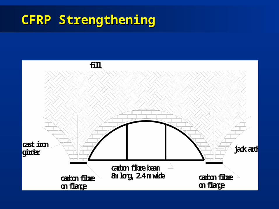
CFRP StrengtheningCFRP Strengthening
carbon fibre beam8m long, 2.4 m widecarbon fibre
on flange
cast irongirder
fill
carbon fibreon flange
jack arch

Prototype and test beam comparisonPrototype and test beam comparison
• PROTOTYPEPROTOTYPE
• 8m long8m long
• 2.4m wide2.4m wide
• TEST BEAMTEST BEAM
• 7.6m long7.6m long
7.4m effective span7.4m effective span
• 1.5m wide1.5m wide
• 0.4m deep0.4m deep

CFRP test beam lay-upCFRP test beam lay-up
1600
1500
500
400
Shell - Spar Cap
Spar -Spar Cap
E Central Ribs
4 x 1300 g/sq.m quadraxial HS carbon1 x 10mm thick PVC foam core4 x 1300 g/sq.m quadraxial HS carbon
F End Ribs
6 x 1300 g/sq.m quadraxial HS carbon1 x 10mm thick PVC foam core6 x 1300 g/sq.m quadraxial HS carbon
G Baseplate Frame
2 x 1300 g/sq.m quadraxial HS carbon1 x 3mm thick PVC foam core2 x 1300 g/sq.m quadraxial HS carbon
H Cover Plates
2 x 1300 g/sq.m quadraxial HS carbon
500
C Spar - Webs
4 x 1300 g/sq.m quadraxial HS carbon1 x 10mm thick balsa core2 x 1300 g/sq.m quadraxial HS carbon
D Spar - Spar Cap
4 x 1300 g/sq.m quadraxial HS carbon4 x 700 g/sq.m unidirectional HM carbon1 x 1300 g/sq.m quadraxial HS carbon4 x 700 g/sq.m unidirectional HM carbon1 x 1300 g/sq.m quadraxial HS carbon4 x 700 g/sq.m unidirectional HM carbon4 x 1300 g/sq.m quadraxial HS carbon
A Shell - Outboard Skins
2 x 1200 g/sq.m quadraxial E glass2 x 1300 g/sq.m quadraxial HS carbon1 x 10mm thick balsa core2 x 1300 g/sq.m quadraxial HS carbon
B Shell - Spar Cap
2 x 1200 g/sq.m quadraxial E glass2 x 1300 g/sq.m quadraxial HS carbon4 x 700 g/sq.m unidirectional HM carbon1 x 1300 g/sq.m quadraxial HS carbon4 x 700 g/sq.m unidirectional HM carbon1 x 1300 g/sq.m quadraxial HS carbon4 x 700 g/sq.m unidirectional HM carbon2 x 1300 g/sq.m quadraxial HS carbon
1200 g/sq.m E glass 0.95mm1300 g/sq.m HS carbon 1.35mm700 g/sq.m HM carbon 0.60mm
Ply Thicknesses
Laminate Schedules
Shell -Outboard Skin
50 25
SparWebs
400
310000
University of SouthamptonDepartment of Civil & Environmental Engineering
Laminate Mechanical Properties (MPa)
PIT TEST BEAM, LAYUP
Scale: 1 : 7 at A4
HM Carbon UD
Material
E Glass Quad
HS Carbon Quad
Baseplate -Frame
4400
Drawn by: S.S.J.Moy
Date: 3rd August 1999
6000 0.31
G
21000
17600
ET
23000
48000
23000
48000
EL
Ribs at 1m centres
0.28
0.31
n

Resin infusion (RIFT)Resin infusion (RIFT)

Finite element meshFinite element mesh

Monitoring performanceMonitoring performance
• Static testStatic test
• Fatigue testFatigue test
• Coupon test programme – long term performanceCoupon test programme – long term performance

Comparison of FE and static testComparison of FE and static test
Load to first ply Load to first ply failurefailure
(kN/m(kN/m22))
Maximum loadMaximum load
(kN/m(kN/m22))
Geometric non-Geometric non-linearitylinearity
6464 7575
Geometric linearityGeometric linearity 6464 132132
Static testStatic test 8585 9292

Comparison of load-deflection graphsComparison of load-deflection graphs
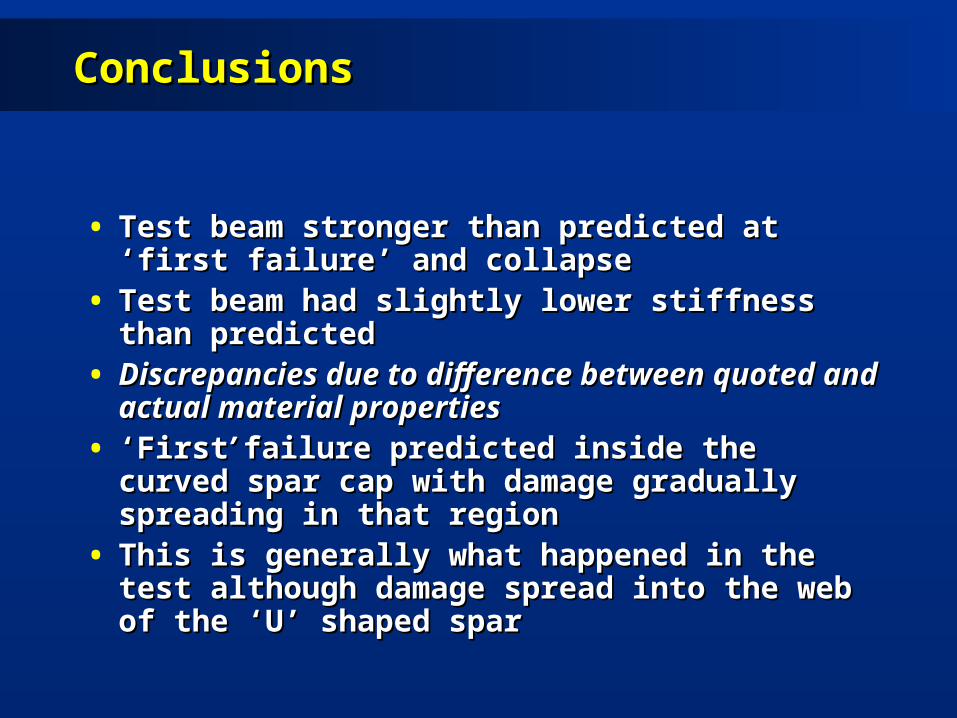
ConclusionsConclusions
• Test beam stronger than predicted at ‘first failure’ Test beam stronger than predicted at ‘first failure’ and collapseand collapse
• Test beam had slightly lower stiffness than Test beam had slightly lower stiffness than predictedpredicted
• Discrepancies due to difference between quoted Discrepancies due to difference between quoted and actual material propertiesand actual material properties
• ‘‘FirstFirst’ ’ failure predicted inside the curved spar cap failure predicted inside the curved spar cap with damage gradually spreading in that regionwith damage gradually spreading in that region
• This is generally what happened in the test This is generally what happened in the test although damage spread into the web of the ‘U’ although damage spread into the web of the ‘U’ shaped sparshaped spar
Introduction to strut Introduction to strut strengtheningstrengthening
• Description of the strut problemDescription of the strut problem
• Outline of test programmeOutline of test programme
• Results from the testsResults from the tests
• Conclusions from the testsConclusions from the tests
• Outline of the strengthening scheme at Outline of the strengthening scheme at Shadwell stationShadwell station
• General conclusionsGeneral conclusions

Strengthening at ShadwellStrengthening at Shadwell
Validation of CFRP strengthening schemeValidation of CFRP strengthening scheme
The problemThe problem• Struts are over 100 years oldStruts are over 100 years old
• Struts have an existing load which cannot be removed Struts have an existing load which cannot be removed before strengtheningbefore strengthening
• The struts are very large, any strengthening must cause The struts are very large, any strengthening must cause minimum disruption to trains running belowminimum disruption to trains running below
Possible validation methodsPossible validation methods• Theoretical studiesTheoretical studies
• Finite element analysisFinite element analysis
• TestingTesting

TestingTesting
1.1. Preliminary tests on 12.2m long struts from RotherhithePreliminary tests on 12.2m long struts from RotherhitheCarried out at NEL, East KilbrideCarried out at NEL, East Kilbride
Problems with local failures at the ends, but indicated benefits of using Problems with local failures at the ends, but indicated benefits of using CFRPCFRP
2.2. Further Tests commissionedFurther Tests commissionedAim:Aim: To investigate the benefits of CFRP reinforcement, even To investigate the benefits of CFRP reinforcement, even
when the strut is preloaded before being reinforcedwhen the strut is preloaded before being reinforced
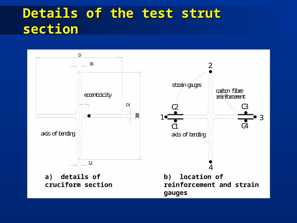
Details of the test strut sectionDetails of the test strut section
12
16
300
D
12 C2
C11
4
C3
C4
2
3
axis of bendingaxis of bending
eccentricitycarbon fibrereinforcement
strain gauges
a) details of cruciform section b) location of reinforcement and strain gauges
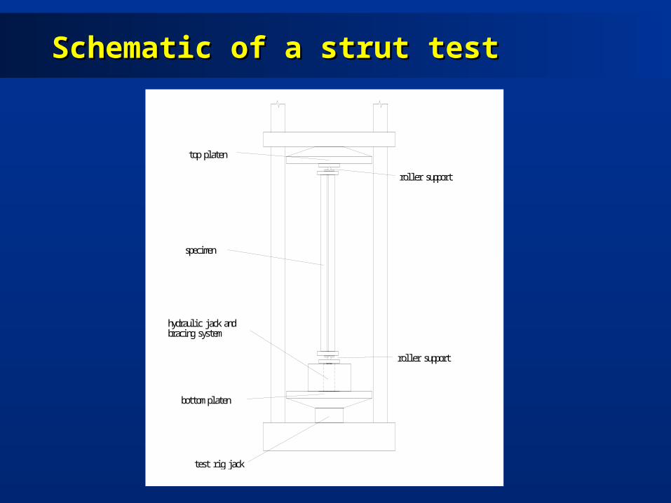
Schematic of a strut testSchematic of a strut test
hydraulic jack andbracing system
bottom platen
test rig jack
specimen
top platen
roller support
roller support
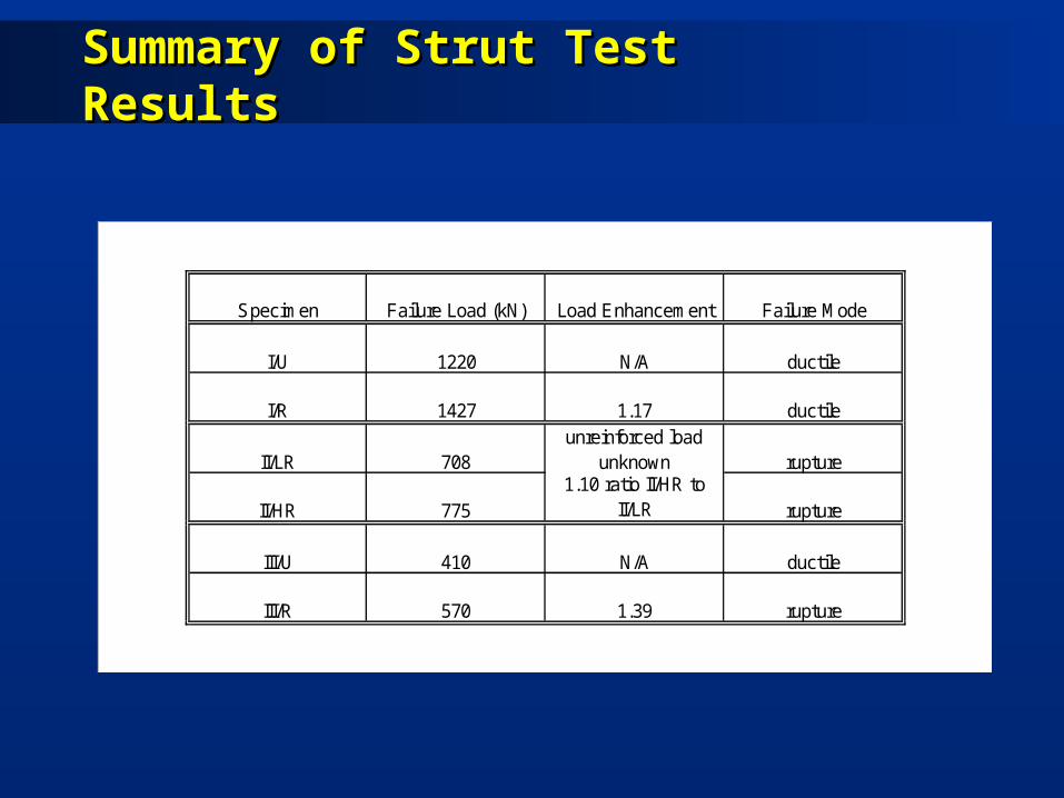
Summary of Strut Test ResultsSummary of Strut Test Results
Specimen Failure Load (kN) Load Enhancement Failure Mode
I/U 1220 N/A ductile
I/R 1427 1.17 ductile
II/LR 708unreinforced load
unknown rupture
II/HR 7751.10 ratio II/HR to
II/LR rupture
III/U 410 N/A ductile
III/R 570 1.39 rupture

Load - Deflection CurvesLoad - Deflection Curves
Load – deflection curves for struts III/U and III/R

Strain distributions across width of strut I/RStrain distributions across width of strut I/R
Conclusions from the Strut TestsConclusions from the Strut Tests
• The bond between the carbon fibre composite The bond between the carbon fibre composite and the cast iron was excellent, giving fully and the cast iron was excellent, giving fully composite behaviour between the carbon fibre composite behaviour between the carbon fibre plates and the cast iron strut.plates and the cast iron strut.
• Even when there was a significant pre-load in the Even when there was a significant pre-load in the cast iron the application of carbon fibre cast iron the application of carbon fibre reinforcement stiffened and strengthened the reinforcement stiffened and strengthened the strut. These benefits were enhanced by the strut. These benefits were enhanced by the application of extra reinforcement.application of extra reinforcement.

Conclusions from the strut testsConclusions from the strut tests
• The carbon fibre composite is usually needed to The carbon fibre composite is usually needed to reinforce the cast iron that is in tension, however reinforce the cast iron that is in tension, however both sides have to be reinforced. In the tests the both sides have to be reinforced. In the tests the carbon fibre composite in compression failed carbon fibre composite in compression failed first (as expected) but the reinforcement on the first (as expected) but the reinforcement on the tension side remained fully effective until tension side remained fully effective until catastrophic failure of the cast iron in tension.catastrophic failure of the cast iron in tension.
The tests confirmed that the use of CFRP is anThe tests confirmed that the use of CFRP is anacceptable approach to the strengthening of in-situacceptable approach to the strengthening of in-situcast iron struts.cast iron struts.

Cast Iron Struts in Vent Shaft Cast Iron Struts in Vent Shaft V129V129
Repair MethodRepair Method
• Aim to reduce loads in existing struts, to increase Aim to reduce loads in existing struts, to increase their strength and to cause minimal disruption to their strength and to cause minimal disruption to the civils worksthe civils works
• Additional steel jacks installedAdditional steel jacks installed
• Cast iron strengthened in-situ using ultrahigh Cast iron strengthened in-situ using ultrahigh modulus carbon fibre using RIFT techniquemodulus carbon fibre using RIFT technique
• Validation completed in LINK and directly funded Validation completed in LINK and directly funded programmesprogrammes
• Project viewed as very important in enabling LUL Project viewed as very important in enabling LUL to introduce lower cost repair techniquesto introduce lower cost repair techniques
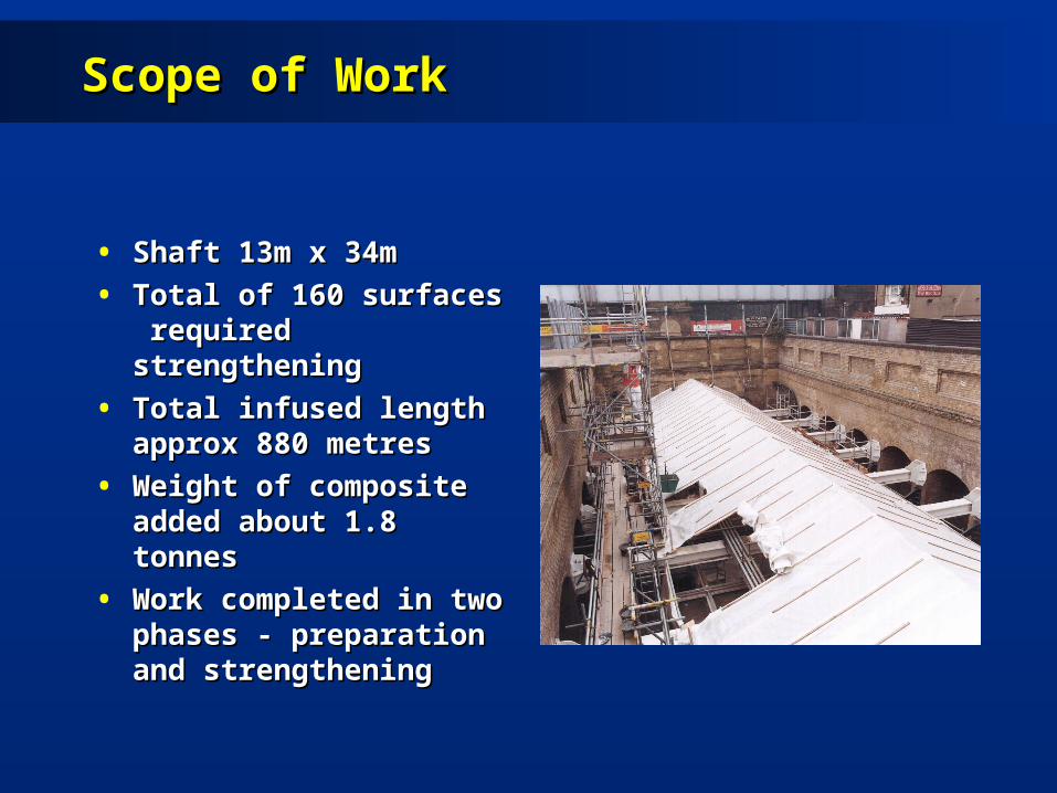
Scope of WorkScope of Work
• Shaft 13m x 34mShaft 13m x 34m
• Total of 160 surfaces Total of 160 surfaces required strengtheningrequired strengthening
• Total infused length Total infused length approx 880 metresapprox 880 metres
• Weight of composite Weight of composite added about 1.8 tonnesadded about 1.8 tonnes
• Work completed in two Work completed in two phases - preparation and phases - preparation and strengtheningstrengthening
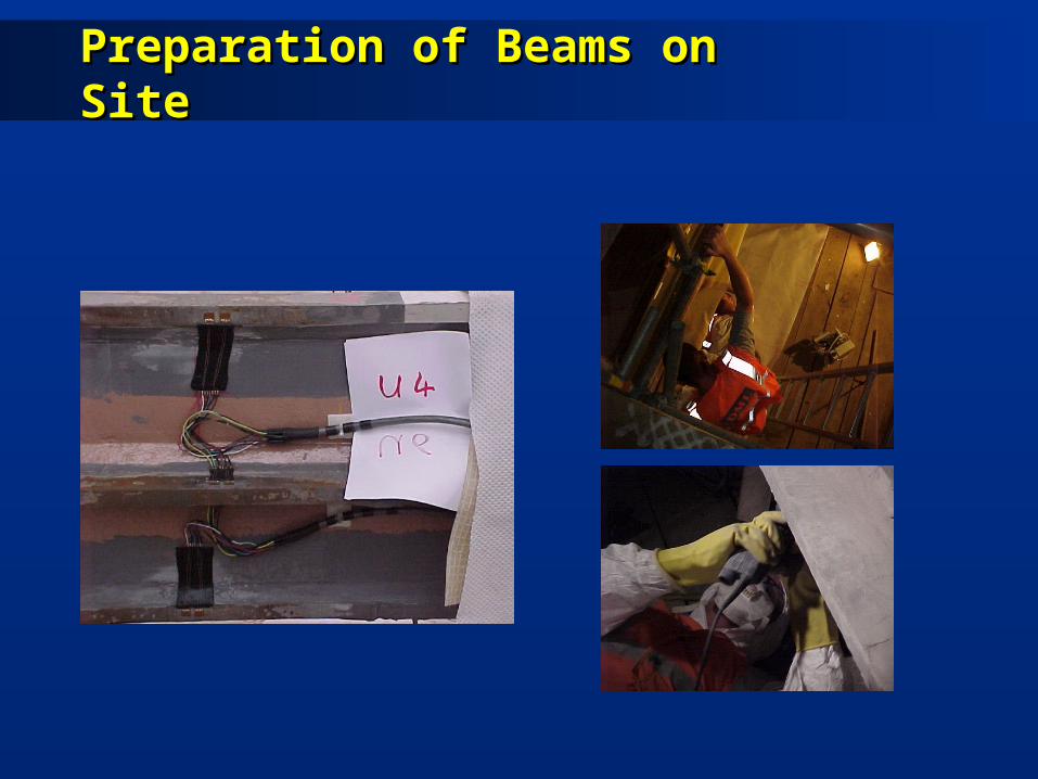
Preparation of Beams on SitePreparation of Beams on Site
Phase II works (Manufacture of Phase II works (Manufacture of stacks)stacks)
• Carbon fibre pre-forms manufactured at DML, DevonportCarbon fibre pre-forms manufactured at DML, Devonport
• High modulus carbon fibre woven to correct width in uni-High modulus carbon fibre woven to correct width in uni-directional tapesdirectional tapes
• Tapes are then cut to the correct lengthTapes are then cut to the correct length
• Plies are built up to match thickness requirementPlies are built up to match thickness requirement
• All consumables included in stacksAll consumables included in stacks
• Stacks are stitched together and packaged for Stacks are stitched together and packaged for transportationtransportation
• On-site processes then minimal and straightforwardOn-site processes then minimal and straightforward
Phase II Works (Installation)Phase II Works (Installation)
• Carbon fibre added to all four arms of cruciforms Carbon fibre added to all four arms of cruciforms and to bracingand to bracing
• Fibre applied using RIFT techniqueFibre applied using RIFT technique• High quality composite formedHigh quality composite formed
• low void contentlow void content
• Full wet out and no dry spotsFull wet out and no dry spots
• Repeatable and consistentRepeatable and consistent
• High bond strengthHigh bond strength• Up to 24 plies applied to armsUp to 24 plies applied to arms• All work completed within 9 weeks by a team of All work completed within 9 weeks by a team of
10 people10 people

Reinforced StrutsReinforced Struts

Post-InstallationPost-Installation
• After installation all beams were painted white to After installation all beams were painted white to reduce heating from direct sunlightreduce heating from direct sunlight
• The temperature increase in the cast iron beams The temperature increase in the cast iron beams and associated expansion is source of highest and associated expansion is source of highest loads in the unreinforced strutsloads in the unreinforced struts
• Inspection regime designed to build confidence Inspection regime designed to build confidence in continuing fitness for purpose of strengthened in continuing fitness for purpose of strengthened beamsbeams
Lessons LearntLessons Learnt
• Main objective to strengthen struts with minimum Main objective to strengthen struts with minimum disruption to the operation of line and minimum disruption disruption to the operation of line and minimum disruption of 140 year old civils work achievedof 140 year old civils work achieved
• Process of applying carbon on site was viewed as very Process of applying carbon on site was viewed as very flexible and simpleflexible and simple
• Problems included the level of surface preparation Problems included the level of surface preparation specified - research carried out in DML-led LINK specified - research carried out in DML-led LINK programme to determine whether this can be relaxedprogramme to determine whether this can be relaxed
• Concerns about effect of climate on resin cure proved Concerns about effect of climate on resin cure proved unfounded. 12 hour cure to be reduced.unfounded. 12 hour cure to be reduced.
• Lack of in-service track record now the major hurdleLack of in-service track record now the major hurdle

Conclusions from strut programmeConclusions from strut programme
• Ultrahigh modulus carbon Ultrahigh modulus carbon fibre has been used to fibre has been used to strengthen cast iron strengthen cast iron cruciform struts on 140 cruciform struts on 140 year old structureyear old structure
• Culmination of 4 years of Culmination of 4 years of research and developmentresearch and development
• Total strengthening Total strengthening amounted to nearly 1km of amounted to nearly 1km of carbon, weighing nearly carbon, weighing nearly 1.8 tonnes1.8 tonnes

General conclusionsGeneral conclusions
• The two research programmes have The two research programmes have demonstrated the potential of CFRP composites demonstrated the potential of CFRP composites for the strengthening of cast iron structures.for the strengthening of cast iron structures.
• Further work needs to be done on the CFRP Further work needs to be done on the CFRP beam. In particular the end supports and the beam. In particular the end supports and the installation procedure need to be sorted out.installation procedure need to be sorted out.
• The strut strengthening at Shadwell continues to The strut strengthening at Shadwell continues to perform well, monitoring continues.perform well, monitoring continues.

AcknowledgementAcknowledgement
• The project partners are grateful to The project partners are grateful to the DETR and EPSRC for funding the the DETR and EPSRC for funding the research under the Partners in research under the Partners in Technology and LINK Inland Surface Technology and LINK Inland Surface Transport Programmes.Transport Programmes.