structural technical proposal - penn state engineering · pdf filestructural technical...
TRANSCRIPT

Structural Technical Proposal By Robert Whitaker
• Robert Whitaker • Structural ~ Parfitt • Parkview at Bloomfield Station • Bloomfield, NJ • 12-12-05
Executive Summary The current structural system for Parkview at Bloomfield Station is composed of
a light gage roof spaced 2’ on center (oc) spanning front to back and panelized bearing light gage walls 4” and 6” wide continuously capped with a steel tube for load distribution purposes. These walls not only hold the 16” deep D500 Hambro® floor system but also act as the main lateral force resisting system for the building. Thin cross bracing straps attached to the light gage bearing walls give these walls the lateral capacity required. There are a total of 38 shear walls in the building: 17 in the North-South direction, 17 in the East-West direction, and 4 concrete masonry unit (cmu) stair towers that resist load mainly in the East-West direction. The precast garage is structurally separate, and only the 4” building separation will be considered for story drift in the lateral review.
Structural Proposal
This proposal covers the analysis and design of a steel braced frame as a replacement for the current light gage bearing wall system. Two different framing orientations for the bar joist floor will be investigated, and analyzed for efficiency and compatibility with the redesigned system. The use of the braced frame system will require less braced frames throughout the building than the current system, creating the use of leaning column frames at some unit separations. There are a total of 22 braced frames in the building: 12 in the North-South direction, and 10 in the East-West direction, along with 4 concrete masonry unit (cmu) stair towers that resist load mainly in the East-West direction.
Calculation Overview
Load and Resistance Factor Design (LRFD) will be used in all spot checks. The analysis will be performed on structural components in the building using RAM, a finite element based analysis program. This program performs lateral load calculations, including seismic and wind from three directions, and will be used to compute the loads for the shear walls in the building. The results from previous Technical Reports will be used and verified in the proposed redesign. A building drift limit is to be computed using the RAM program, and the members will be sized using the Manual of Steel Construction ~ 3rd Edition. Finally, a Portal Frame analysis will be used to spot check calculated end reactions in specific frame members.

Structural Technical Proposal By Robert Whitaker
Building Overview Parkview at Bloomfield Station is a uniquely shaped
six story residential condominium building located in Bloomfield, NJ. The building is most noticeable for its long sprawling irregular footprint. The building also wraps around a precast parking garage that is only visible from the train station side. The building is nestled between the Second River to the south, Washington St. to the west, a tree filled lot in the east, and a train station for the Midtown Line to the north. There are 197 condominium units and 330 parking spaces included in the design of this building. Numerous storage facilities are located in the parking garage and an exercise room is also included, located above the lobby area. A drop off circle, located just off of the tree lined entry drive, allows for easy access for visitors and taxi services.
Garage: 152,748 ft2 Building: 300,725 ft2
Per Floor: 50,121 ft2 Total: 453,473 ft2
• Robert Whitaker • Structural ~ Parfitt • Parkview at Bloomfield Station • Bloomfield, NJ • 12-12-05
Structural Overview The structural system for Parkview at Bloomfield Station is composed of a light
gage roof spaced 2’ on center (oc) spanning front to back with some hip conditions incorporated, bearing on exterior and corridor walls, and girder trusses at hip roof conditions. The bearing walls are panelized bearing light gage steel stud walls 4” and 6” wide continuously capped with a steel tube, HSS 4x4x5/16” and HSS 6x4x5/16” respectively, for load distribution purposes. Beams and transfer beams provide bearing points for the floor system, columns, and roof trusses. A 16” deep Hambro® D500™
1

Hambro Floor System Note: Typical bearing walls are light gage walls (not those shown above)
floor system makes up the composite rigid floor diaphragm and consists of joists spaced at 4’ oc connected to a 3” concrete floor (3000psi). The 16” joists span the short direction of the living units (typically 30’) and Hambro RTC joists (top cord only joists) span the corridor (typically 6’). The total ceiling to floor depth is 21” and allows the mechanical duct work to pass through the open webs of the joists.
Along with the bearing light gage walls, there are two braced frame systems at
the drive aisles that pass under the building. The upper floors in these sections are supported by a series of one or two story columns that are part of this W18 braced frame system. All 6 floors of the building have mainly the same floor plans with the exception of 4 locations: an entry/lobby unit, a 2 story drive aisle, a 1 story drive aisle, and a 1st floor exit route. In these areas, transfer beams are utilized requiring much larger beam sizes. The two story braced frame system used in the 2 story drive aisle consists of nineteen W18 columns placed along bearing lines. There is a similar system at the one story drive aisle consisting of twelve columns. While these braced frames act as the lateral force resisting system in these two unique areas, the main lateral force resisting system for the building is a shear wall system provided by thin steel cross bracing straps attached to the light gage shear walls.
Precast Garage (not included)
2 Story Drive Aisle
Driv
eA
isle
Lobby Unit
The precast garage located at the center of the building, consists of precast
double-T planks bearing on load bearing elements. The vertical elements in the garage transfers its’ load to pile caps encompassing 100 ton H piles drilled to bedrock (ranging from 42-53 ft below the slab-on-grade surface). The precast garage is structurally separated from the main building by a 4” air gap and by 4” expansion joints at building connection points. Because of this the garage will not be considered in this building proposal and will remain as is.
Finally, continuous 2’-6” wide footings make up most of the building bearing
wall support under the 4” slab-on-grade foundation. However, larger spread footings (typically 4’x4’) are utilized below leaning column point loads. The spread footings at the drive aisle’s braced frames merge together and resemble larger single spread footings. The precast garage's footings are separate from that of the main building and encompass a deep foundation system rather than the buildings shallow footing system.
2

Problem Statement
The original Hambro floor system performed better than any of the alternate
system designs that were analyzed in Technical Report #2. The computer results of Technical Report #3 were somewhat vague due to the number of lateral force resisting elements and size of the building. The hand analysis did indicate that the original design performed adequately based on the lateral loadings; however, there were a few areas of failing performance established by the computer generated model. It was assumed that these inadequacies were a result of user input and modeling errors, not a negative reflection on the design of the lateral system. The aspect of the original structural design best suited for further investigation is the lateral force resisting system due to this analytical uncertainty.
Furthermore, due to the nature of the structure, it must be erected by specialized
contractors not only for the light gage walls but also for the Hambro flooring system. Finding certified contractors for both of these specialized systems are hard to locate in some areas and may slow the speed of the project, increasing the overall cost of the project per Means Building Construction Cost Data (RS Means).
Proposed Solution
The proposed alternative to the light gage shear walls will be a braced steel frame.
This new frame will necessitate less shear walls throughout the building while still maintaining the same architectural layout. The braced steel frame will allow more lateral strength capacity with less lateral force resisting members. The red lines in figure 1 below are the existing shear walls and the dark lines represent the braced frame.
Lateral Force Resisting Elements Braced Steel Frame
Leaning Column Frame CMU Stair Tower
Figure 1
3

The dark lines on figure 2 below represent the new steel braced frame locations in the building. The other unit separation locations (remaining red lines) are frames consisting of leaning columns, or the concrete masonry unit (cmu) stair tower.
The braced steel frame will only extend as far as the corridor and will have W18 columns. The W18 shape columns will be equal to or smaller than a W18x71 (bf = 7.64) allowing them to fit within the 11” unit separation wall. The additional room needed in these walls to frame out around the columns will be taken out of the 6’ corridor space, boxing out at column locations, and by extensions to the overall building length if necessary. The existing corridors are 1’-0” greater than required by the International Building Code (IBC) 2000 and therefore a reduction of up to 1’ is allowed. The cross bracing, making up the lateral force resisting system, will be composed of C15x50 (bf = 3.72) and bolted to the columns. This will allow for back to back attachment while remaining within the width of the column flange, see figure 3.
Lateral Force Resisting Elements Braced Steel Frame
Leaning Column Frame CMU Stair Towe
Figure 2
r
Figure 3 The beams will span the depth of the unit (typically 31’) and cantilever the width
of the corridor. The beams the throughout the building will be W18x65 beams and will require a 2” bulkhead to cover their extension below the ceiling line. These beams will support 16K5 steel bar joists at 2’-0” oc with 3 rows of bridging. The joists are topped with 5½” concrete over composite metal decking to act as the floor system. This floor system will have a ceiling to floor depth of 23½” which is approximately the same as the existing Hambro system’s depth. The floor to floor height will increase by 2 inches to 10’-8”, which will not interfere with any code restrictions. Gravity floor loads and lateral loads will be checked with loads calculated from chapters 3, 4, 6, 7, and 9 of ASCE 7-05 as opposed to the ASCE 7-98 code that was originally used. Using this updated code with higher strength requirements will be accommodated for in the deeper floor system and the more robust steel braced frame used to resist lateral loads.
4

Solution Method
Load and Resistance Factor Design (LRFD)
will be used to verify adequacy of the W18 trial sizes stated above through a truss analysis method. The design of the steel braced frame will be based mainly on chapters 3-5 (Tension, Columns, and Beams) in the Manual of Steel Construction ~ 3rd Edition (LRFD Manual). The trial sizes for the columns and cross bracing will be checked for adequacy based on beam/column interactions found in chapter 6 of the LRFD Manual.
Figure 4 Truss Analysis
~Lateral Loading
The bar joist system will be analyzed for
structural strength capacity based on manufacturer’s data. Likewise, the 5½” concrete and composite metal decking will be checked using load tables created by the deck manufacturer. Along with the calculations for the floor system, the uplift at the exterior corridor wall will need to be checked to see if the cantilevered beam will require camber.
Figure 5 Virtual Work Method
~Story Drift
Story drift will be spot checked using virtual work method and common braced frame assumptions outlined in the introduction to steel course at Penn State. The trial sizes will be inputted into RAM to compute interactions between gravity and lateral loadings over the entire building and compute the effects of live load patterns through a finite element analysis program. This data will then be checked with the hand spot check calculations to verify critical loadings and locations in the building. The torsion on the lateral system will be checked by the RAM model and will be used to determine the adequacy of the braced frame system.
5

Tasks and tools to be used in each solution
Braced Frame Alternative Task 1. Establish Trial Member Sizes
a. Determine beam sizes based on a 38’ max span and 21” ceiling height requirements. Determine if the use of shear studs as outlined in chapter 5 of the LRFD Manual are required for span and loading requirements.
b. Establish if 5½” thickness of concrete and composite deck meets strength and vibration requirements based on manufacturer’s data. Check for adequacy of three hour fire requirements based on Underwriter Laboratories (UL) testing.
c. Determine the most economical floor framing direction. There are 2 options for framing directions: 31’ in the North-South direction or 38’ in the East-West direction bearing on steel beams that cantilever across the corridor, see figure 6 below. The systems will be compared by costs found in RS Means.
d. Verify that the exterior corridor cantilever is adequate for loading.
30’-
0”±1
’-0”
Bar
Jois
t
Fra
min
g D
irect
ion
5’-6
” D
eck
Corridor
Alternate Bar Joist Bearing on Cantilevered Beams
38’-0” Typical
Figure 6
Task 2. Determine Floor Loadings
a. Find factored self weight based on member selections from Task 1. b. Establish superimposed dead loads based on building plans and use. c. Verify gravity loads established in Technical Report #2 with ASCE 7-
98 chapters 3, 4, and 7. d. Verify lateral loads established in Technical Report #2 with ASCE 7-
98 chapters 6 and 9.
6

Task 3. Complete Computer Analysis a. Input the steel braced frame members into a 3D RAM finite element
analysis program. b. Assign lateral and gravity loading to the model based on the loads
calculated in task 2. Set the computer analysis to analyze full and partial live load conditions to establish live load patterns on the structure.
c. Verify adequacy of member sizes based on lateral loads occurring at cardinal directions and at 45 degree angles to the structure.
d. Compare results for member sizes, loading on the footing, and story drift with the results of the hand calculations.
Task 4. Complete Hand Spot Checks
(To be used to verify specific members as needed) a. Using the Tributary Area Method for lateral loads, select the steel
braced frame with the largest tributary area and calculate the seismic and wind story forces. Apply story forces to nodes and uniform gravity loads to horizontal beams.
b. Adapting the Shear Wall Analysis excel spreadsheet created in Technical Report #3, calculate the axial and torsional loads on each braced frame in the system.
c. Using the Truss Analysis, calculate axial and bending moments. d. Determine nodal loads using Portal Frame Analysis e. Select critical members within the truss and verify size using chapter 6
of the LRFD Manual based on interaction of the member’s axial and bending loads.
f. Determine story drift by the use of Virtual Work Method, as illustrated in the introduction to steel class at Penn State.
g. Calculate new forces that are transferred to the foundation and size the foundation system based on the Terzaaghi or Meyerhof Bearing Capacity Methods.
Task 5. Final Analysis
a. Design a cross brace-to-column connection capable of transferring the maximum calculated force. The connections chapter of the LRFD Manual and course notes from the Penn State master’s connection course will be used to evaluate the connections. Calculate column to column splice connections for the frame in the same manner.
b. Establish the final steel braced frame based on the RAM model. c. Verify that all calculated member and footing sizes in the final design
of the structure correspond with the greatest loading of the structure. d. Prepare updated plans reflecting these changes to the structure.
7
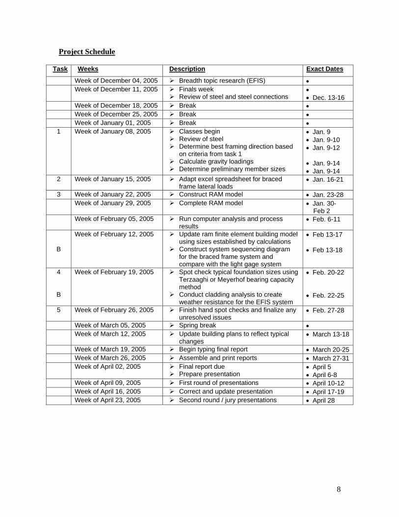
Project Schedule
Task Weeks Description Exact Dates
Week of December 04, 2005 Breadth topic research (EFIS) • Week of December 11, 2005 Finals week •
Review of steel and steel connections • Dec. 13-16 Week of December 18, 2005 Break • Week of December 25, 2005 Break • Week of January 01, 2005 Break • 1 Week of January 08, 2005 Classes begin
Review of steel Determine best framing direction based
on criteria from task 1 Calculate gravity loadings
• Jan. 9 • Jan. 9-10 • Jan. 9-12 • Jan. 9-14
Determine preliminary member sizes • Jan. 9-14 2 Week of January 15, 2005 Adapt excel spreadsheet for braced
frame lateral loads • Jan. 16-21
3 Week of January 22, 2005 Construct RAM model • Jan. 23-28 Week of January 29, 2005 Complete RAM model • Jan. 30-
Feb 2 Week of February 05, 2005 Run computer analysis and process
results • Feb. 6-11
B
Week of February 12, 2005 Update ram finite element building model using sizes established by calculations
• Feb 13-17
Construct system sequencing diagram for the braced frame system and compare with the light gage system
• Feb 13-18
4
B
Week of February 19, 2005 Spot check typical foundation sizes using Terzaaghi or Meyerhof bearing capacity method
• Feb. 20-22
Conduct cladding analysis to create weather resistance for the EFIS system
• Feb. 22-25
5 Week of February 26, 2005 Finish hand spot checks and finalize any unresolved issues
• Feb. 27-28
Week of March 05, 2005 Spring break • Week of March 12, 2005 Update building plans to reflect typical
changes • March 13-18
Week of March 19, 2005 Begin typing final report • March 20-25 Week of March 26, 2005 Assemble and print reports • March 27-31 Week of April 02, 2005 Final report due • April 5
Prepare presentation • April 6-8 Week of April 09, 2005 First round of presentations • April 10-12 Week of April 16, 2005 Correct and update presentation • April 17-19 Week of April 23, 2005 Second round / jury presentations • April 28
8

Project Timeline
9