structural peer review statement · • structural design criteria narrative document provided by...
TRANSCRIPT

STRUCTURAL PEER REVIEW STATEMENT
This structural peer review and report, dated 24 February 2017, is complete for the foundation submission.
Structural Peer Reviewer Name: Benjamin M. Cornelius
Leslie E. Robertson Associates
Structural Peer Reviewer Address: 40 Wall Street, FL 23
New York, NY 10005
Project Address: 45 Broad Street, New York City, Block #25, Lot #7, 10
Department Application Number for Structural Work: #121190772
Structural Peer Reviewer Statement:
I ,_Benjamin M. Cornelius_, am a qualified and independent NYS licensed and registered engineer in accordance with BC Section 1627.4, and I have reviewed the structural plans, specifications, and supplemental reports for 45 Broad St., Block #25, Lot #7, 10, Application #121190772 and found that the structural design shown on the plans and specifications generally conforms to the foundation and structural requirements of Title 28 of the Administrative Code and the 2014 NYC Construction Codes. The Structural Peer Review Report is attached.
New York State Registered Design Professional
(for Structural Peer Review only)
Name ___Benjamin M. Cornelius___
Signature ___________________ Date_02/24/17
Cc: Project Owner: Madison Equities; Andrew Harris Project Registered Design Professional: WSP; Johan Leonard
121190772 ES875292092DEPT OF BLDGS Job Number Scan Code

LERA
45 Broad Street
Structural Peer Review Report
Foundations
Leslie E. Robertson Associates, RLLP
Consulting Structural Engineers
40 Wall Street, 23rd Floor
New York, NY 10005
Tel: (212) 750-9000
Fax: (212) 750-9002
http://www.lera.com
24 February 2017

P1105 – 45 Broad Street
Structural Peer Review Report – Foundation
24 February 2017
Leslie E. Robertson Associates, RLLP LERA Consulting Structural Engineers
45 Broad Street Structural Peer Review Report – Foundation
TABLE OF CONTENTS
1. Introduction…………………….………………………………………………..…………………1
1.1 Documents Reviewed…………………………………………………………………….....1
2. Design Criteria………………………………………………………………………................1
2.1 Geotechnical Report…………………………………………..…………………….……....1
2.2 Structural Design Criteria…..……………………………………………………….……..2
3. Superstructure Review………………………………………………………………….……..2
3.1 Architectural and Structural Drawings………………………………………..……...2
3.2 ETABS Model…………………..…………………………………………………….……………2
3.2.1 Base Shear Check…………………..……..…………………………………………3
3.3 Load Path………………………..………………………………………………………………...4
4. Pressure Slab.……………….………………………………………………………………………4
4.1 Global Behaviour……………………………………………………………………….……….5
4.2 Pressure Slab Reinforcement……..……..……………………………………….………5
5. Secant Pile Wall……………….…………………………………………………………………..6
6. Caissons…….…………………….…………………………………………………………………10
6.1 Axial Capacity……………………..…………………………………………….……...........10
6.2 Lateral Capacity….………………………………..……………………………….………….11
7. Caisson Caps….……………………………………………………………………………………11
7.1 Flexural Capacity……………………..……………………………………….……...........11
7.2 Shear Capacity….……………………..……………………………………….……...........12
8. Strap Beams……………………………..………………………………………...………….....12
8.1 Strap Beam Schedule……………..……………………………………….…….............12
8.2 Grade Beam Flexural and Shear Capacity……………………..….……............12

P1105 – 45 Broad Street
Structural Peer Review Report – Foundation
24 February 2017
Leslie E. Robertson Associates, RLLP LERA Consulting Structural Engineers
9. Perimeter Foundation Walls Acting as Retaining Walls……..…...……….….12
9.1 Flexural Capacity….…..……………………..……………………………….……............13
9.2 Shear Capacity….……………………..……………………………………….……............14
10. Conclusion……………………………………………………………………………...……….…15
Appendix A Drawing List
Appendix B Structural Design Criteria form WSP
Appendix C Structural Design Criteria Narrative form WSP
Appendix D Geotechnical Report
Appendix E SOE Plan Drawing
Appendix F Caisson and Secant Pile Wall Capacity Summary Tables from WSP

P1105 – 45 Broad Street
Structural Peer Review Report - Foundations
24 February 2017
Leslie E. Robertson Associates, RLLP LERA Consulting Structural Engineers
1
1. Introduction
At the request of Mr. Andrew Harris of Madison Equities, Leslie E. Robertson Associates, R.L.L.P. (LERA)
has conducted a Structural Peer Review of the foundation design of 45 Broad Street, as required by the
New York City Building Code section 1617. This report presents our findings and conclusions.
The building is located at 45 Broad Street in New York City, and the structural design was prepared by
WSP.
1.1 Documents Reviewed We have reviewed the following documents:
• Structural and Architectural Drawings, listed in Appendix A.
• Structural Design Criteria listed in Drawing FO-001.00 and attached as Appendix B.
• Structural Design Criteria Narrative document provided by WSP and attached as Appendix C.
• The geotechnical report prepared by Langan Engineering, titled Amended Geotechnical Engineering
Study for 45 Broad Street dated 29 April 2016, attached to this report as Appendix D.
• SOE Plan Drawing, attached as Appendix E.
• Caisson and Secant Pile Wall Capacity Summary Tables provided by WSP and attached as Appendix
F.
2. Design Criteria
We reviewed drawing FO-001 Foundation Notes, the Structural Design Criteria document provided by
WSP, as well as the geotechnical report. Our observations are discussed below.
2.1 Geotechnical Report We note that, while the geotechnical report recommends the use of a mat foundation and rock anchors,
the drawings show the foundation system to be caissons. Upon request, WSP provided documentation
from the geotechnical engineer substantiating the foundation system they have selected (caissons) and
the allowable caisson loads they used in their design. We recommend that these criteria be shared with
the DOB, that the geotechnical report be updated as appropriate, and that the title and date of the
report be updated in Drawing FO-001.00.
In addition, we note that the earthquake design data shown on FO-001.00 are different than what is
provided in the geotechnical report dated 29 April 2016. We recommend that the EOR coordinate this
data with the recommendations of the geotechnical report.
• Site Class: B (per geotechnical report), D (shown on dwg FO-001.00)
• Sds: 0.187g (per geotech report), 0.295g (shown on dwg FO-001.00)
• Sd1: 0.049g (per geotech report), 0.117g (shown on dwg FO-001.00)
It should be noted, however, that the design data shown on FO-001.00 is more conservative than what
is recommended in the geotechnical report.

P1105 – 45 Broad Street
Structural Peer Review Report - Foundations
24 February 2017
Leslie E. Robertson Associates, RLLP LERA Consulting Structural Engineers
2
We further note that the following information was missing from the geotechnical report:
• Recommendation for earthquake loads on permanent foundation walls are not included in the
report.
• Recommendation for loads from adjacent buildings on permanent foundation walls are not
included in the report.
2.2 Structural Design Criteria Drawing FO-001 Foundation Notes generally includes the necessary design loads and other information
pertinent to the structural design; however, we recommend the EOR review the following list of items
that should also be included and provide the following additional design criteria:
• A loading schedule for different floor occupancy, including floor live load, partition loads and
other superimposed dead loads (NYCBC 1603.1.1, 1603.1.2, 1603.1.10)
• Permissible Live load reductions, where allowed by code
• Roof snow loads (NYCBC 1603.1.4)
• Base shear for wind loads (NYCBC 1603.1.5)
• Flood design loads (or water head) (NYCBC 1603.1.8)
• Design criteria loading of foundation walls due to static and seismic earth pressures, surcharge,
and hydrostatic pressures. (NYCBC 1603.1.9)
3. Superstructure Review
3.1 Architectural and Structural Drawings We reviewed and compared the architectural drawings and WSP’s structural foundation drawings, and
found that the structural foundation drawings were in general conformance with the architectural
drawings.
3.2 ETABS Model A global building model developed using ETABS was provided by WSP. This model was reviewed,
compared with the structural and architectural drawings, and updated as necessary to be consistent
with the submitted structural and architectural drawings and code requirements. The model was used
to obtain loads for the design checks of foundation elements. Figure 1 below shows different views of
the ETABS model.

P1105 – 45 Broad Street
Structural Peer Review Report - Foundations
24 February 2017
Leslie E. Robertson Associates, RLLP LERA Consulting Structural Engineers
3
(a)
(b)
Figure 1 – Global ETABS Model (a) Looking North, (b) Looking South
3.2.1 Base Shear Check
The ETABS model was used to compare the building base shear from earthquake loads shown on
drawing FO-001.00. We could not compare wind load base shears as they were not provided, however,
we generated our own code-conforming wind loads for use in our analysis and review.
We found that the base shear from code-prescribed earthquake loads match the base shear values
reported in the design criteria drawing FO-001.00, and that base shear from code-prescribed wind loads
generated are in scale for the size and type of building. Figures 2 and 3 below present the global shears
and overturning moments taken from our ETABS model for wind and earthquake loads.

P1105 – 45 Broad Street
Structural Peer Review Report - Foundations
24 February 2017
Leslie E. Robertson Associates, RLLP LERA Consulting Structural Engineers
4
(a)
(b)
Figure 2 - Global Model Shears for (a) Wind Loads (Envelope), and (b) Earthquake Loads (Envelope)
(a)
(b)
Figure 3 - Global Model Overturning Moments for (a) Wind Loads (Envelope), and (b) Earthquake
Loads (Enveloped)
3.3 Load Path We reviewed a sampling of typical floors, walls, columns as well as foundation walls, caisson caps and
caissons, and found they generally were acceptably proportioned for the size and type of building. The
superstructure appears to have a continuous load path.
4. Pressure Slab
The pressure slab was checked for its global behavior with the building against the buoyancy force as
well as locally for the reinforcement provided. A SAFE model was developed to obtain loads from the
water uplift load combinations. Upward water pressures obtained using the information on the water
table provided in the geotechnical report and downward loads from the ETABS model were combined in
the SAFE model.

P1105 – 45 Broad Street
Structural Peer Review Report - Foundations
24 February 2017
Leslie E. Robertson Associates, RLLP LERA Consulting Structural Engineers
5
4.1 Global Behavior
The geotechnical report recommends the design ground water at El. +12 ft., meaning that the water
head is equal to 20’ – 71/2” ft.
A hand calculation was made to review the net uplift of the building, and it was found that the self-
weight of the building (CDL+SDL) is greater than the buoyancy force. From this results, we believe that
there will be no uplift issues under gravity-alone load cases.
4.2 Pressure Slab Reinforcement
The slab reinforcement of the 24” pressure slabs was checked using the SAFE model described above,
using the information provided in the notes on drawing FO-100.00 and additional reinforcement shown
in plan. Table 1 below summarizes the findings, while Figure 4 indicates the locations where the capacity
of the pressure slab was reviewed.
Table 1 – Summary of Pressure Slab Capacity Check
Pressure Slab Reinforcement
DCR
Flexure
DCR
Shear
Mbottom @ 1 #11 @ 6 + 3 - #11 @ 12 0.58 1.15
Mbottom @ 2 #11 @ 6 + 14 - #11 @ 6 0.33 0.99
Mtop @ 3 #11 @ 6 0.60 0.26
Mbottom @ 4 #11 @ 6 0.61 0.72
Figure 4 – Location of Pressure Slab Reinforcement Checks (FO-100.00)
To address the overstress identified in Table 1, we recommend the EOR revise the design of the pressure
slab where it frames into the perimeter wall and to columns 100 and 102 for shear.

P1105 – 45 Broad Street
Structural Peer Review Report - Foundations
24 February 2017
Leslie E. Robertson Associates, RLLP LERA Consulting Structural Engineers
6
5. Secant Pile Wall
The ETABS model described in Section 3.2 of this report was used to obtain the axial loads in the secant
pile wall and we compared these loads to the secant pile wall capacities listed in the summary table
provided by WSP. Tables 2 to 5 below summarize the findings, while Figure 5 indicates the locations of
the overstresses observed in the secant piles. It is important to note that only the maximum DCR per
secant pile is shown on the figure.
Table 2 – Summary of Secant Pile Type “A” Axial Capacity Check
Caisson
Compression
(kip)
DCR
Tension
(kip) DCR
370 916.98 0.92 -91.46 0.30
372 830.42 0.83 111.76 -
4298 968.44 0.97 124.57 -
8602 1116.07 1.12 99.34 -
8610 1267.66 1.27 47.76 -
8797 912.69 0.91 26.01 -
8801 927.64 0.93 115.21 -
8805 954.12 0.95 77.98 -
8809 1096.50 1.10 -25.93 0.09
8829 909.06 0.91 -127.77 0.43
9008 1323.81 1.32 -585.12 1.95
9014 1181.60 1.18 -419.90 1.40
9021 1044.29 1.04 -255.07 0.85
9058 779.96 0.78 83.27 -
9062 719.44 0.72 97.45 -
12201 915.79 0.92 -288.64 0.96

P1105 – 45 Broad Street
Structural Peer Review Report - Foundations
24 February 2017
Leslie E. Robertson Associates, RLLP LERA Consulting Structural Engineers
7
Table 3 – Summary of Secant Pile Type “B” Axial Capacity Check
Caisson
Compression
(kip)
DCR
Tension
(kip) DCR
20 2761.70 0.66 -1421.93 1.05
21 3403.48 0.81 -1441.34 1.07
25 3547.47 0.84 -1513.88 1.12
66 3523.62 0.84 -1521.11 1.13
214 3532.99 0.84 166.21 -
219 3697.31 0.88 -827.35 0.61
261 3509.88 0.84 -1487.30 1.10
4105 3491.52 0.83 -1524.51 1.13
4351 3232.33 0.77 127.37 -
8308 2873.89 0.68 -1418.95 1.05
8713 2543.81 0.61 -263.43 0.20
8719 3020.64 0.72 -490.56 0.36
8753 2094.89 0.50 -1318.86 0.98
8757 1867.33 0.44 -917.90 0.68
8895 2717.14 0.65 -1423.93 1.05
8899 2794.59 0.67 -1419.78 1.05
8901 2845.28 0.68 -1425.34 1.06
9112 3824.78 0.91 164.42 -
9129 2728.08 0.65 27.04 -
9131 2971.84 0.71 81.21 -
9139 3720.56 0.89 175.64 -
Table 4 – Summary of Secant Pile Type “C” Axial Capacity Check
Caisson
Compression
(kip)
DCR
Tension
(kip) DCR
48 3998.63 0.63 -1697.08 0.51
113 3887.29 0.61 -1666.54 0.50
339 3715.19 0.59 -1626.41 0.49
4062 3523.88 0.55 -1591.66 0.48
4078 3327.25 0.52 -1562.06 0.47
8739 2755.30 0.43 -1787.20 0.53
8741 2870.24 0.45 -1718.14 0.51
8743 2979.51 0.47 -1697.44 0.51
8745 3080.05 0.49 -1696.92 0.51
8747 3168.43 0.50 -1696.46 0.51

P1105 – 45 Broad Street
Structural Peer Review Report - Foundations
24 February 2017
Leslie E. Robertson Associates, RLLP LERA Consulting Structural Engineers
8
Table 5 – Summary of Secant Pile Type “24” Axial Capacity Check
Caisson
Compression
(kip)
DCR
Tension
(kip) DCR
1 1613.58 0.70 -789.24 0.99
2 1889.33 0.82 -836.24 1.05
8959 1621.92 0.71 -786.82 0.98
8963 1629.94 0.71 -784.86 0.98
8967 1641.15 0.71 -784.18 0.98
8971 1655.76 0.72 -784.77 0.98
8975 1673.95 0.73 -786.72 0.98
8979 1694.13 0.74 -789.71 0.99
8983 1716.90 0.75 -793.84 0.99
8987 1742.37 0.76 -799.19 1.00
8991 1771.68 0.77 -806.05 1.01
8995 1805.21 0.78 -814.39 1.02
8999 1842.70 0.80 -824.02 1.03
We observed that there are compression and tension overstresses in the secant pile wall under
combined gravity and wind loads. We recommend the EOR to revise the secant pile layout to address
overstresses.

P1105 – 45 Broad Street
Structural Peer Review Report - Foundations
24 February 2017
9
Figure 5 – Location of Secant Pile Overstresses
0.92
0.83
0.97
1.12
1.27
0.91
0.93
0.95
1.10
0.91
1.04
0.78
0.72
0.84
0.88
0.77
0.61
0.72
0.910.650.710.89
0.63 0.61 0.59 0.55 0.520.99 1.050.980.980.980.980.980.990.991.001.011.021.03
1.95
1.40
0.96
1.05 1.071.121.13 1.101.131.05
0.98
0.68
1.05 1.051.060.53 0.51 0.51 0.51 0.51
-10
0
10
20
30
40
50
60
-80 -60 -40 -20 0 20 40 60 80 100 120
Compression Tension

P1105 – 45 Broad Street
Structural Peer Review Report - Foundations
24 February 2017
Leslie E. Robertson Associates, RLLP LERA Consulting Structural Engineers
10
6. Caissons
6.1 Axial Capacity The ETABS model described in Section 3.2 of this report was used to obtain the axial loads in the
caissons. The caisson groups shown in plan were reviewed and we found that caisson designs were
sufficient for their axial loads. Table 6 below summarizes the finding, while Figure 6 indicates the
locations of caissons reviewed.
Table 6 – Summary of Caisson Axial Capacity Check
Caisson
Compression
(kip)
DCR
Tension
(kip) DCR
3960 2217.68 0.92 192.55 0.16
4133 1868.59 0.78 183.26 0.15
8294 2197.47 0.92 94.13 0.08
8345 1665.12 0.69 377.30 0.31
8351 1717.23 0.72 387.68 0.32
8362 2243.08 0.93 20.62 0.02
8414 1217.23 0.51 40.65 0.03
8551 1844.71 0.77 6.98 0.01
8560 1833.62 0.76 50.87 0.04
300 5234.67 0.87 399.20 0.13
8491 4856.41 0.81 882.74 0.29
8512 5078.51 0.85 681.88 0.23
10253 5135.37 0.86 93.05 0.03
10485 5300.24 0.88 136.80 0.05
11222 5204.29 0.87 26.83 0.01
Figure 6 – Location of Caissons Checked (from FO-100.00)

P1105 – 45 Broad Street
Structural Peer Review Report - Foundations
24 February 2017
Leslie E. Robertson Associates, RLLP LERA Consulting Structural Engineers
11
6.2 Lateral Capacity
The average lateral load on the caissons was reviewed by comparing the total base shear from seismic
and wind loads and the total horizontal capacity of the caissons. Table 7 below summarizes the results
obtained.
Table 7 – Summary of Caisson Lateral Load Capacity Check
Load Base Shear (kip)
Total Capacity
(kip) DCR
EQx 2100 5650 0.37
EQy 2100 5650 0.37
Wind x 2800 5650 0.5
Wind y 5477 5650 0.97
From the sample calculations, we believe that the caissons capacities provided in Drawing FO-200.00 are
adequate for the building demand. We recommend that the geotechnical report be updated to include
the allowable caisson loads. See also comments in Section 2.1.
7. Caisson Caps
7.1 Flexural Capacity The flexural capacity of caisson cap type C6 under columns 100 and 102 was reviewed using the
information shown on FO-200.00. Table 8 summarizes the results obtained.
Table 8 – Summary of Caisson Caps Flexural Capacity Check
Caisson Cap Reinforcement DCR
C6 Long Way 29 – #11 0.45
C6 Short Way 22 - #11 0.45
Per ACI 9.6.1.2 the minimum area of flexural reinforcement shall be the greater of (a) and (b).
In this case, the governing equation is (a), requiring a minimum reinforcement area of 0.5%. The current
area of flexural reinforcement shown for type C6 caisson cap is 0.19% in the short way and 0.36% in the
long way. We recommend the EOR revise the caisson cap design of all caps to meet the requirement of
minimum area of flexural reinforcement.

P1105 – 45 Broad Street
Structural Peer Review Report - Foundations
24 February 2017
Leslie E. Robertson Associates, RLLP LERA Consulting Structural Engineers
12
7.2 Shear Capacity All caissons are within distance d from the face of the wall or column above, therefore not contributing
to shear in the caisson caps.
8. Strap Beams
8.1 Flexural Capacity The flexural capacity of strap beams was reviewed using the information shown on FO-100.00. Table 9
summarizes the results obtained.
Table 9 – Summary of Strap Beam Flexural Capacity Check
Strap Beam Reinforcement DCR
SB1 Top: 126 - #11 (7 layers) 0.67
From the sample calculations, we believe the flexural design of the strap beams is adequate.
8.2 Shear Capacity The shear capacity of strap beams was reviewed using the information shown on FO-100.00. Table 10
summarizes the results obtained.
Table 10 – Summary of Strap Beam Shear Capacity Check
Strap Beam Legs Size Spacing DCR
SB1 6 #5 6” 0.27
From the sample calculations, we believe the shear design of the strap beams is adequate.
9. Perimeter Foundation walls Acting as Retaining Walls
The design of the perimeter foundation retaining wall (East side of the building) and of the shear wall
acting as a retaining wall (North side of the building) were reviewed based on the lateral pressure design
data (see Figure 7) provided in the geotechnical report prepared by Langan, dated 29 April 2016, and the
reinforcement details shown on 2/FO-300.00 and S-940.00.

P1105 – 45 Broad Street
Structural Peer Review Report - Foundations
24 February 2017
Leslie E. Robertson Associates, RLLP LERA Consulting Structural Engineers
13
(a)
(b)
Figure 7 – Lateral Soil, Hydrostatic and Surcharge Pressures (a) North Wall, (b) East Wall
9.1 Flexural Capacity
Table 11 below summarizes the results of our foundation wall flexural capacity checks.
Table 11 – Summary of Perimeter Retaining Walls Flexural Capacity Check
Wall Reinforcement DCR
North Wall #9 @ 10 0.23
East Wall #7 @ 12 0.78
From the sample calculations, we believe the flexural design of the retaining walls is adequate.

P1105 – 45 Broad Street
Structural Peer Review Report - Foundations
24 February 2017
Leslie E. Robertson Associates, RLLP LERA Consulting Structural Engineers
14
9.2 Shear Capacity
Table 12 below summarizes the results of our foundation wall shear capacity checks.
Table 12 – Summary of Perimeter Retaining Walls Shear Capacity Check
Wall Reinforcement DCR
North Wall - 0.36
East Wall - 0.45
From the sample calculations, we believe the shear design of the retaining walls is adequate.
P1105 – 45 Broad Street
Structural Peer Review Report - Foundations
24 February 2017
Leslie E. Robertson Associates, RLLP LERA Consulting Structural Engineers
15
10. Conclusions
In conclusion, we find that the geotechnical recommendations need be updated to include the design
criteria used by the EOR in the design of the foundations and secant pile wall. Provided that the final
geotechnical recommendations confirm the design criteria given in the drawings and other documents
provided to us, we find the design of the foundation of 45 Broad Street to be in general conformance with
the structural and foundation design provisions of the New York City Building Code. In some cases,
however, we have noted overstresses and detailing issues that need to be addressed by the Engineer of
Record. In these instances, we have recommended that the EOR revisit the design as indicated in the body
of this report.
The opinions expressed in this report represent our professional view, based on the information
made available to us. In developing these opinions, we have exercised a degree of care and skill
commensurate with that exercised by professional engineers licensed in the State of New York for
similar types of projects. No other warranty, expressed or implied, is made as to the professional
advice included in this report.
Respectfully submitted,
LESLIE E. ROBERTSON ASSOCIATES, R.L.L.P.
_____________________________
BENJAMIN M. CORNELIUS
Partner-In-Charge

P1105 – 45 Broad Street
Structural Peer Review Report – Foundation
24 February 2017
Leslie E. Robertson Associates, RLLP LERA Consulting Structural Engineers
Appendix A Drawing List

STRUCTURAL SHEET LIST
SHEET NUMBER SHEET NUMBER DATE
FO-001 GENERAL NOTES & LEGEND 2016.11.07
FO-100 FOUNDATION PLAN 2016.11.07
FO-110 SUB-CELLAR 1 FRAMING PLAN 2016.11.07
FO-120 CELLAR FRAMING PLAN 2016.11.07
FO-150 PILE CAP REINFORCEMENT PLAN 2016.11.07
FO-200 TYPICAL FOUNDATION DETAILS 1 2016.11.07
FO-201 TYPICAL FOUNDATION DETAILS 2 2016.11.07
FO-202 TYPICAL FOUNDATION DETAILS 3 2016.11.07
FO-203 TYPICAL FOUNDATION DETAILS 4 2016.11.07
FO-300 FOUNDATION SECTIONS 1 2016.11.07
FO-301 FOUNDATION SECTIONS 2 2016.11.07
FO-310 FOUNDATION SECTIONS 3 2016.11.07
S-010 GROUND FLOOR FRAMING PLAN 2016.11.07
S-940 SHEAR WALL PLAN 2016.11.07
S-945 TYPICAL SHEARWALL DETAILS 2016.11.07
S-950 COLUMN SCHEDULE 1 2016.11.07
S-951 COLUMN SCHEDULE 2 2016.11.07
S-955 TYPICAL COLUMN DETAILS 2016.11.07
S-960 TYPICAL SUPERSTRUCTURE DETAILS 1 2016.11.07
S-961 TYPICAL SUPERSTRUCTURE DETAILS 2 2016.11.07
S-962 TYPICAL SUPERSTRUCTURE DETAILS 3 2016.11.07
S-963 TYPICAL SUPERSTRUCTURE DETAILS 4 2016.11.07
S-964 TYPICAL MANSONRY DETAILS 2016.11.07
S-980 TYPICAL STAIR SECTIONS 2016.11.07
ARCHITECTURAL SHEET LIST
SHEET NUMBER SHEET NUMBER DATE
A-098.00 SUB-CELLAR 2 2016.12.09
A-099.00 SUB-CELLAR 1 2016.12.09
A-100.00 CELLAR 2016.12.09
A-101.00 GROUND FLOOR 2016.12.09
A-102.00 GROUND FLOOR MEZZANINE -
A-103.00 2ND FLOOR PLAN - MACHANICAL 2016.04.22
A-104.00 3RD TO 8TH FLOOR COMMERCIAL 2016.04.22
A-109.00 9TH FLOOR - COMMERCIAL 2016.04.22
A-110.00 10TH FLOOR - COMMERCIAL -
A-111.00 11TH FLOOR - MECHANICAL 2016.04.22
A-112.00 11TH FLOOR - MEZZANINE 2016.04.22
A-113.00 12TH FLOOR - AMENITY 2016.04.22
A-114.00 13TH FLOOR - AMENITY 2016.04.22
A-115.00 14TH TO 29TH FLOOR - TIER 1 2016.04.22
A-130.00 30TH FLOOR - TIER 1 -
A-132.00 32TH FLOOR - TIER 1 - TRANSFER 2016.04.22
A-133.00 33RD FLOOR - OUTDOOR 2016.04.22

ARCHITECTURAL SHEET LIST
SHEET NUMBER SHEET NUMBER DATE
A-134.00 34TH FLOOR - MECHANICAL 2016.04.22
A-135.00 34TH FLOOR - MEZZANINE 2016.04.22
A-136.00 35TH - 50TH FLOOR AND 54TH - 63RD FLOOR TIER 2 2016.04.22
A-151.00 51ST FLOOR - TIER2 - TRANSFER 2016.04.22
A-152.00 52ND FLOOR - MECHANICAL 2016.04.22
A-153.00 53RD FLOOR - WINDBREAK -
A-164.00 64TH, 66TH, 68TH, 70TH FLOOR - TIER 2 - LOWER 2016.04.22
A-165.00 65TH, 67TH, 69TH FLOORS - TIER 2 - UPPER 2016.04.22
A-171.00 71ST FLOOR - TIER 2 - TRANSFER 2016.04.22
A-172.00 72ND FLOOR - TIER 3 2016.04.22
A-176.00 76TH FLOOR - TIER 3 - TRANSFER -
A-177.00 77TH FLOOR - MECHANICAL 2016.04.22
A-178.00 78TH FLOOR - MECHANICAL 2016.04.22
A-179.00 78TH FLOOR - MEZZANINE -
A-180.00 79TH FLOOR - ELEVATOR MACHINE ROOM 2016.04.22
A-181.00 BULKHEAD -

P1105 – 45 Broad Street
Structural Peer Review Report – Foundation
24 February 2017
Leslie E. Robertson Associates, RLLP LERA Consulting Structural Engineers
Appendix B Structural Design Criteria from WSP

ARCH
ITEC
T
CLIE
NT
STRU
CTUR
AL E
NGIN
EER
MEP
ENGI
NEER
GEOT
ECHN
ICAL
ENG
INEE
R
LAND
SCAP
E AR
CHIT
ECT
SCAL
EPR
OJEC
T
DOB
PAGE
NO.
DOB
FILE
NO.
DRAW
ING
NO.
LIGH
TING
DES
IGNE
R
CURT
AIN
WAL
L CO
NSUL
TANT
John A. Cetra
State of New YorkRegistered ArchitectNo. 018861
CetraRuddy Architecture DPC
584 Broadway Suite 401New York, NY 10012212.941.9801
PR
EL
IMIN
AR
Y -
NO
T F
OR
CO
NS
TR
UC
TIO
N©
CET
RARU
DDY
ARCH
ITEC
TURE
DPC
WSP Group
228 East 45th Street, 3rd FlNew York, NY 10017212.687.9888
BuroHappold Engineering
100 BroadwayNew York, NY 10005212.334.2025
LANGAN
21 Penn Plaza360 West 31st Street, 8th FlNew York, NY 10001212.479.5400
Madison 45 Broad
Development, LLC
105 Madison AvenueNew York, NY 10016
BuroHappold Engineering
100 BroadwayNew York, NY 10005212.334.2025
Ventresca Design, LLC
44-02 Eleventh St, Suite 203Long Island City, NY 11101212.600.0033
1590109
45
BROAD
STREET
NEW YORK NY 10004
PROGRESS PRINT 03/11/16
As Noted
FO-001.00
FOUNDATION NOTES
– BASIC WIND SPEED (3 SECOND GUST) = 98 mph– WIND IMPORTANCE FACTOR = 1– WIND EXPOSURE = C– INTERNAL PRESSURE COEFFICIENT = ±0.18
xxxx-xx-xx xxxx

P1105 – 45 Broad Street
Structural Peer Review Report – Foundation
24 February 2017
Leslie E. Robertson Associates, RLLP LERA Consulting Structural Engineers
Appendix C Structural Design Criteria Narrative from
WSP

45 Broad Street
Madison Equities, LLC
Pizzarotti IBC, LLC
CetraRuddy Architecture
December 30, 2016

QM
Issue/revision Issue 1 Revision 1 Revision 2 Revision 3
Remarks
Date 12-30-2016
Prepared by JL
Signature
Checked by HM
Signature
Authorized by SM
Signature
Project number B1590-109
File reference
WSP USA One Penn Plaza 250 W 34th St, 2nd Fl New York, NY 10119 http://www.wsp-usa.com
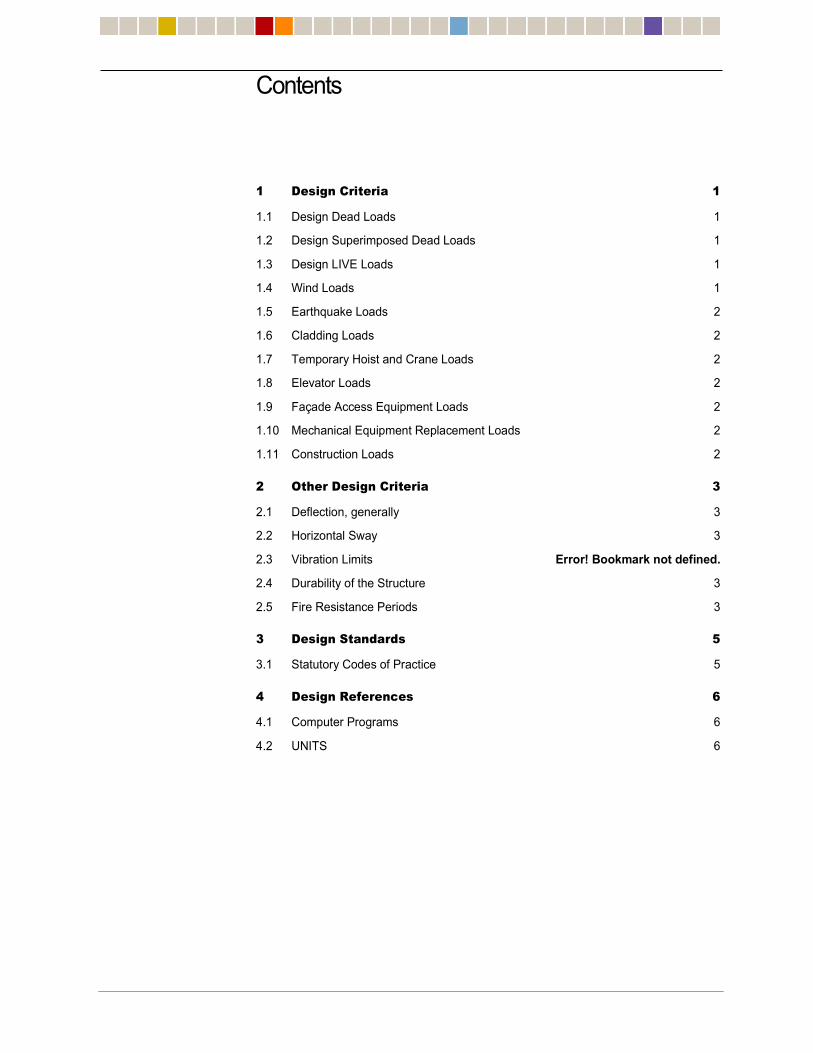
Contents
1 Design Criteria 1
1.1 Design Dead Loads 1
1.2 Design Superimposed Dead Loads 1
1.3 Design LIVE Loads 1
1.4 Wind Loads 1
1.5 Earthquake Loads 2
1.6 Cladding Loads 2
1.7 Temporary Hoist and Crane Loads 2
1.8 Elevator Loads 2
1.9 Façade Access Equipment Loads 2
1.10 Mechanical Equipment Replacement Loads 2
1.11 Construction Loads 2
2 Other Design Criteria 3
2.1 Deflection, generally 3
2.2 Horizontal Sway 3
2.3 Vibration Limits Error! Bookmark not defined.
2.4 Durability of the Structure 3
2.5 Fire Resistance Periods 3
3 Design Standards 5
3.1 Statutory Codes of Practice 5
4 Design References 6
4.1 Computer Programs 6
4.2 UNITS 6

1
STRUCTURAL DESIGN CRITERIA
1 Design Criteria
DESIGN LOADS
1.1 DESIGN DEAD LOADS
Dead loads are calculated from the known self-weight of the materials used for the
construction of the frame.
1.2 DESIGN SUPERIMPOSED DEAD LOADS
Additional allowance is made for fixed finishes and services as follows:
Residential Floors (ceiling, partitions, finishes) 15 psf
Balconies 30 psf
Lobby/public spaces
(ceiling, dense finishes) 30 psf
Retail
(ceiling, dense finishes) 30 psf
Mechanical room
(ceiling, suspended services, partitions) 30 psf
Elevator/stair lobbies within core
(Ceiling, suspended services and dense finishes) 30 psf
Roof
(Finishes, insulation, tapered slab, ceiling) 30 psf
1.3 DESIGN LIVE LOADS
The following loads have been adopted in the design:
Residential 40 psf
Balconies 100 psf
Staircases 100 psf
Main roof (access for maintenance only) 40 psf
Mechanical areas 150 psf
Public areas (lobby) 100 psf
The building structure will be checked for the loadings applied from the proposed
temporary cranes and hoists by the Contractor, with the capacity of the structure being
adjusted where necessary.
1.4 WIND LOADS
Wind loads acting on the main building frame and the various elements of cladding were
determined by requirements from NYCBC 2014.

2
1.5 EARTHQUAKE LOADS
Static Analysis using New York City Building Code – 2014 Edition Ss = 0.281 g S1 = 0.073 g Seismic Importance Factor = 1.0 Site Class = D Ordinary Reinforced Concrete Shearwalls R = 5
1.6 CLADDING LOADS
Unitised window wall 30 psf
1.7 TEMPORARY HOIST AND CRANE LOADS
The permanent structure will be designed to support the design loads provided by the
Contractor from the temporary cranes and hoists.
1.8 ELEVATOR LOADS
All elevator shaft walls and elevator machine room slabs will be designed for elevator
loadings provided by the elevator consultant.
1.9 FAÇADE ACCESS EQUIPMENT LOADS
The structures will be designed to support the window cleaning equipment loads to be
provided by the façade access consultant.
1.10 MECHANICAL EQUIPMENT REPLACEMENT LOADS
All equipment replacement in and around the building is to be undertaken in such a
manner as not to exceed the imposed loadings indicated on the WSP PB loading plans.
1.11 CONSTRUCTION LOADS
To be determined by the Contractor.

3
2 Other Design Criteria
2.1 DEFLECTION, GENERALLY
Vertical floor deflections for concrete floor construction:
Calculation of deflections includes long-term effects after installation of partitions/façade:
Spandrel beam/slab edge live load + super-imposed dead load deflection: ½”
Super-imposed + live load deflection: span / 480 (beam supported at each end)
span / 240 (cantilever beam)
2.2 HORIZONTAL SWAY
Earthquake
Sway deflection of any one story: minimum of h/250 or ½”
2.3 DURABILITY OF THE STRUCTURE
The structure is to have a design life of 50 years. Some structural elements, such as
those with concrete wearing surfaces and corrosion protection will require periodic
inspection and maintenance.
2.4 FIRE RESISTANCE PERIODS
The following fire resistance periods are adopted in the design of the building:
Beams and slabs: 2 hours
Columns: 3 hours
Material Properties
Concrete
Shearwalls: f’c = 14,000psi to 8,000psi E = 7,080ksi to 5,100ksi
Columns: f’c = 14,000psi to 8,000psi E = 7,080ksi to 5,100ksi
Link Beams: f’c = 14,000psi to 8,000psi E = 7,080ksi to 5,100ksi
Floor Slabs: f’c = 6,000psi to 8,000psi E = 4,415ksi to 5,100ksi
Bearing Foundations: f’c = 10,000psi E = 5,700ksi
Foundation Walls: f’c = 14,000psi to 10,000psi E = 7,080ksi to 5,700ksi
4
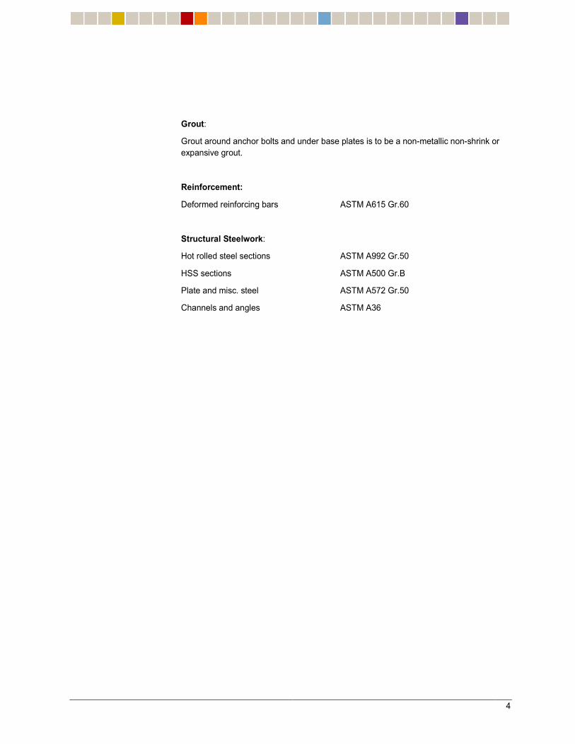
Grout:
Grout around anchor bolts and under base plates is to be a non-metallic non-shrink or
expansive grout.
Reinforcement:
Deformed reinforcing bars ASTM A615 Gr.60
Structural Steelwork:
Hot rolled steel sections ASTM A992 Gr.50
HSS sections ASTM A500 Gr.B
Plate and misc. steel ASTM A572 Gr.50
Channels and angles ASTM A36
5
3 Design Standards
3.1 STATUTORY CODES OF PRACTICE
New York City Building Code - 2014
ACI-318 Building Code Requirements for Structural Concrete and Commentary
ACI-530-08: Building Code Requirements and Specifications for Masonry Structures and
Related Commentaries
AISC-13thed.: LRFD Manual of Steel Construction

6
4 Design References
Other publications used include:
IBC-2009: International Building Code
ASCE7-05 Minimum Design Loads for Buildings and Other Structures
AISC Design Guide 11 – Floor Vibrations Due To Human Activity
4.1 COMPUTER PROGRAMS
RAM Structural System Version 14.02.01
SAFE Version 12.0
ETABS non-linear Version 2015
4.2 UNITS
The structural calculations will be completed using the following units. Length: feet and inches Mass: Kip / g Force: Kip Stress: K/in2
Moment: Kip-ft Velocity: Miles/hour Acceleration: ft/s2 and milli-g

P1105 – 45 Broad Street
Structural Peer Review Report – Foundation
24 February 2017
Leslie E. Robertson Associates, RLLP LERA Consulting Structural Engineers
Appendix D Geotechnical Report

AMENDED GEOTECHNICAL
ENGINEERING STUDY for
45 Broad Street
New York, New York
Prepared For:
Madison 45 Broad Development LLC 105 Madison Avenue, 9th Floor
New York, New York 10016
Prepared By:
Langan Engineering, Environmental, Surveying
and Landscape Architecture, D.P.C. 21 Penn Plaza
360 West 31st Street, 8th Floor
New York, New York 10001
Tasos Papathanasiou, P.E.
N.Y. Professional Engineer License No. 085329
Marc Gallagher, P.E.
N.Y. Professional Engineer License No. 08166471
29 April 2016
170394201

Amended Geotechnical Engineering Study
45 Broad Street
New York, New York
Page i of ii
29 April 2016
Langan Project No. 170394201
TABLE OF CONTENTS
INTRODUCTION ........................................................................................................................ 1
SITE DESCRIPTION ................................................................................................................... 1
Adjacent Buildings ................................................................................................................ 2
Adjacent NYCT Subway Structure ....................................................................................... 3
PROPOSED DEVELOPMENT ..................................................................................................... 3
REVIEW OF PUBLISHED INFORMATION ................................................................................. 4
Regional Geology .................................................................................................................. 4
Historical Land Use ............................................................................................................... 4
Flood Hazard .......................................................................................................................... 4
SUBSURFACE EXPLORATION ................................................................................................. 5
2007 Borings .......................................................................................................................... 5
2016 Borings .......................................................................................................................... 5
2016 Cone Penetration Tests (CPTs) .................................................................................... 6
2016 Test Pit .......................................................................................................................... 6
Groundwater Observation Wells .......................................................................................... 7
Laboratory Testing ................................................................................................................ 7
SUBSURFACE CONDITIONS .................................................................................................... 7
Fill [Class 7] ............................................................................................................................ 7
Silt and Clay [Class 5b, 4c, and 6] ......................................................................................... 8
Clayey Sand [Class 6] ............................................................................................................ 8
Decomposed Rock [Class 1d] ................................................................................................ 9
Bedrock [Class 1a, 1b, and 1c] .............................................................................................. 9
Groundwater ......................................................................................................................... 9
EVALUATION AND DISCUSSION .......................................................................................... 10
FOUNDATION DESIGN RECOMMENDATIONS ..................................................................... 11
Seismic Design Parameters ................................................................................................ 11
Liquefaction Evaluation ...................................................................................................... 12
Foundation System ............................................................................................................. 12
Pressure Slabs ..................................................................................................................... 16
Permanent Groundwater Control ....................................................................................... 16
Permanent Below@Grade Walls .......................................................................................... 18
GEOTECHNICAL CONSTRUCTION RECOMMENDATIONS .................................................. 20

Amended Geotechnical Engineering Study
45 Broad Street
New York, New York
Page ii of ii
29 April 2016
Langan Project No. 170394201
Excavation ............................................................................................................................ 20
Subgrade Preparation for Foundation Mat on Rock ......................................................... 20
Temporary Groundwater Control ....................................................................................... 21
Preconstruction Conditions Survey and Monitoring During Construction ..................... 21
Construction Documents and Quality Control .................................................................. 21
Owner and Contractor Obligations .................................................................................... 22
LIMITATIONS........................................................................................................................... 22
FIGURES
Figure 1 .................................................................................................... Site Location Map
Figure 2 ...................................................................................................... Bedrock Geology Map
Figure 3 ...................................................................................................... Surficial Geology Map
Figure 4 .............................................................................................................. Viele Map (1865)
Figure 5 ..................................................................................... FEMA Flood Insurance Rate Map
Figure 6 .......................................................................................... Subsurface Investigation Plan
Figure 7 ......................................................................................................... Subsurface Profile A
Figure 8 ......................................................................................................... Subsurface Profile B
Figure 9 .............................................................. New York City Building Code Liquefaction Chart
APPENDICES
Appendix A ................................................................................................................ Boring Logs
Appendix B .......................................................................... Observation Well Construction Logs
Appendix C ............................................................................................. Laboratory Test Results
Appendix D .................................................................................... Test Pit Log and Photographs
Appendix E ........................................................................ Cone Penetration Tests (CPTs) Report

Amended Geotechnical Engineering Study
45 Broad Street
New York, New York
Page 1 of 23
29 April 2016
Langan Project No. 170394201
1
INTRODUCTION
This amended report updates the results of our amended geotechnical engineering study for
the proposed development of 45 Broad Street in Manhattan, New York. The purpose of this
study was to develop recommendations for foundations and other geotechnical aspects of
design and construction. Our work was performed in accordance with our approved
19 November 2015 proposal. Our study included a review of available information, field
investigations, engineering evaluation, and development of geotechnical recommendations in
accordance with the 2014 New York City Building Code. Amendments to our 23 November
2010 report were made to:
1. Include information from a supplementary subsurface investigation performed in
January and February of 2016;
2. Account for new design drawings prepared by the architect (CetraRuddy) and
subsequent discussions with the project team and Madison 45 Broad Development;
3. Account for new foundation drawings prepared by the structural engineer (WSP) in
March 2016.
Elevations given are based on the survey prepared by Empire State Layout, Inc., dated
21 January 2016, and are with respect to the North American Vertical Datum (NAVD88) unless
otherwise noted.
SITE DESCRIPTION
The 45 Broad Street site is on the east side of Broad Street between Exchange Place and
Beaver Street in lower Manhattan, New York. The site is identified as Block 25, Lot 7 on the
New York City Tax Maps and is currently vacant. The site is within the block bound by
Exchange Place on the north, Beaver Street on the south, Broad Street on the west, and
William Street on the east. Existing buildings are adjacent to the site on the north, south, and
east. Broad Street borders the site on the west. A New York City Transit (NYCT) tunnel is
located under Broad Street. A site location map is presented in Figure 1.
The vacant site is T?shaped with about 63 feet of frontage on Broad Street and a site area of
about 12,600 square feet (SF), with surface elevation varying from about el 9 to el 11. An eight?
story structure with one cellar level was demolished in 2007 to make way for the previous
owner’s proposed redevelopment. The former cellar was backfilled with demolition debris to

Amended Geotechnical Engineering Study
45 Broad Street
New York, New York
Page 2 of 23
29 April 2016
Langan Project No. 170394201
2
sidewalk grade with the former foundations, including piles and pile caps and basement slab,
left in place.
Adjacent Buildings
Existing structures adjacent to the site on the north, south, and east are shown in Figure 6:
41 Broad Street – Claremont Preparatory School
The Claremont Preparatory School (41 Broad Street) north of the site is a nine? to twelve?story
brick and stone structure with a footprint of about 11,000 SF built in 1929. Available
architectural drawings indicate that 41 Broad Street has two below?grade levels with the
subcellar level having a finished?floor elevation about 28 feet below the adjacent sidewalk
grades(about el ?17.5). Available foundation drawings show the structure supported by spread
footings. Bearing capacity was not indicated on the available plans. Construction drawings
appear to indicate that, along the southern end of the site (adjacent to 45 Broad), the
foundations consist of piers bearing on bedrock constructed by way of a continuous cofferdam.
25 Broad Street
25 Broad Street is a T?shaped lot to the east occupied by a 20?story brick and stone structure
with a 263?foot frontage along Exchange Place, built around 1900. The building previously had
an about 50?foot?wide section that extended to the south, adjacent to 41 and 45 Broad Street to
the east. This 4,200?square?foot extension was demolished to be part of the previous 45 Broad
Street development scheme. Available architectural drawings show that the entire building
footprint of 25 Broad Street, including the demolished southern part, has one cellar level. The
finished?floor elevations of the below?grade levels are not known, and no foundation drawings
are available for this structure. A steam?line easement running in the north?south exists within
the part of 25 Broad Street that was demolished.
40 Exchange Place
Beyond 25 Broad Street to the east is 40 Exchange Place, a 20?story brick and stone
commercial building with one below?grade level, built in 1902. The finished?floor elevations of
the below?grade levels are not known, and no foundation drawings are available for this
structure.

Amended Geotechnical Engineering Study
45 Broad Street
New York, New York
Page 3 of 23
29 April 2016
Langan Project No. 170394201
3
15 William Street
Adjacent to 25 Broad Street to the southeast is 15 William Street, a 44?story concrete
residential structure with below?grade levels that extend about 45 feet below the surrounding
grades (about el ?34.5) built in 2005. The foundation wall and excavation support system for
15 William Street consists of a permanent reinforced secant pile wall drilled into the underlying
bedrock.
55 Broad Street
55 Broad Street, adjacent to the south, is a brick building varying from 6 to 31 stories, built in
1968. A one?story extension borders the project site to the southeast. Available drawings
show that the building has one below?grade level at about el ?7.5 and that the structure is
supported on driven H?piles bearing on bedrock.
Adjacent NYCT Subway Structure
The existing NYCT subway tunnels and structures for the BMT and IND J, M, and Z lines run
beneath Broad Street about 20 feet west of the site; in addition, the Broad Street station
(servicing lines J and Z) is nearby. NYCT drawings (Broad Street Station, South?End, 1928)
show that the subway consists of a reinforced concrete box constructed using cut?and?cover
methods. Vents in the Broad Street sidewalk are as close as about 10.5 feet to the property
line. The base of the rail closest to the site is at about el ?12.5. The tunnel foundation level is at
about el ?16.5, which is about 28 feet below the adjacent sidewalk grades. Because the
proposed construction will be within 200 feet of the subway tunnel, NYCT approval of
excavation and foundation construction is required to obtain building permits.
PROPOSED DEVELOPMENT
According to CetraRuddy’s architectural drawings, the project will consist of about 8,950 square
feet of development with an 83?story (plus mechanical penthouse) tower. The tower will extend
to about 1,150 feet above grade and will have about 30?foot setback from the south property
line along Broad Street. The top of the ground floor slab will be about el 11.4. The development
in the rear “hammerhead” portion of the site is not proposed.
The building will include three cellar levels below the podium to be used for storage and
amenities, including a swimming pool. The top of lowest cellar slab will be about 32 feet below
sidewalk grade; the corresponding elevation is about el ?20.7.

Amended Geotechnical Engineering Study
45 Broad Street
New York, New York
Page 4 of 23
29 April 2016
Langan Project No. 170394201
4
The tower will be concrete and will have a central structural core extending the entire height of
the structure, with perimeter columns carrying the remaining load. The foundation loads and
contact pressure at the base of the tower is not yet available at the time of this report; however
WSP expects the contact pressure to be below 40tsf.
REVIEW OF PUBLISHED INFORMATION
Regional Geology
The United States Geological Survey “Bedrock and Engineering Geologic Maps of New York
County and Parts of Kings and Queens Counties, New York, and Parts of Bergen and Hudson
Counties, New Jersey” (see Figure 2) shows the bedrock formation underlying the site is
Manhattan Schist.
Pleistocene glacial activity modified the landscapes and surficial features of Manhattan,
Brooklyn, Queens, and Long Island. Glaciers scoured uplands and deposited varying amounts
of till (an unsorted mixture of sand, clay and boulders) across the lowlands and valleys. The
USGS surficial geology map indicates that the site is underlain by glacial outwash deposits
generally consisting of sand and gravel. See Figure 3 for the USGS surficial geology map.
Historical Land Use
We reviewed the “Sanitary & Topographical Map of the City and Island of New York” (Viele,
1856), which indicates the east portion of the site near Broad Street is on manmade land and
the west part of the site was a meadow. Before being filled, Broad Street was an inlet from
the East River known as Broad Canal. See Figure 4 for the relevant part of the Viele Map.
Flood Hazard
We reviewed the Federal Emergency Management Agency (FEMA) Preliminary Flood Insurance
Rate Map (FIRM), dated 5 December 2013 (Community Panel No. 360497 0088 G). According
to the Preliminary FIRM, the western part of the site is within Zone X (areas within the
0.2 percent annual chance floodplain, i.e., 500?year flood). The eastern part of the site is within
Zone AE (areas within the 1 percent annual chance floodplain, i.e., 100?year flood), which has a
base flood elevation of el 11 NAVD88. Design of the building must follow the flood protection
requirements of the NYCT and ASCE?24. The relevant part of the Preliminary FIRM is
presented in Figure 5.

Amended Geotechnical Engineering Study
45 Broad Street
New York, New York
Page 5 of 23
29 April 2016
Langan Project No. 170394201
5
SUBSURFACE EXPLORATION
A summary of our subsurface explorations performed in August 2007 and February 2016 are
presented below.
2007 Borings
Six borings (B?1 through B?6) were drilled as part of our 2007 subsurface exploration. All
borings were drilled by Craig Test Boring, Inc. with a CME track?mounted drill rig, under
Langan’s full?time special inspection. The borings were advanced using mud rotary drilling
techniques and a tricone roller bit with drilling fluid and steel casing providing soil support.
Borings were advanced to between 59 and 65 feet below grade.
The upper 10 feet of each boring was drilled without sampling to permit the boring to be
advanced through demolition debris and the remnant cellar?floor slab. Standard Penetration
Test (SPT)1 N?values were measured and soil samples were typically obtained beginning at
about 10 feet below the existing site grades and at 5?foot intervals thereafter. Samples were
retrieved using a standard 2?inch outside?diameter split?spoon sampler driven by a 140?pound
automatic hammer in accordance with ASTM D1586. NX?size rock cores were obtained at each
boring location in accordance with ASTM D2113. Rock core recovery2 and rock quality
designation (RQD)3 was recorded for each core run.
Recovered soil samples were visually examined and classified in the field in accordance with
the Building Code. Soil classifications, N?values, and other field observations were recorded on
field logs. See Appendix A for the boring logs and Figure 6 for the boring location plan.
2016 Borings
Two borings (B?7 and B?8) were drilled in the rear of the lot (“hammerhead”) as part of our 2016
supplemental subsurface exploration program. The borings were drilled by Craig Geotechnical
Drilling Co., Inc. with a truck?mounted drill rig under Langan’s full?time special inspection. . The
borings were advanced using mud?rotary drilling techniques and a tricone roller bit with drilling
fluid and steel casing providing soil support. Both borings were advanced to 55 feet below
grade.
1 The Standard Penetration Test is a measure of the soil density and consistency. The SPT N?value is defined as the number of
blows required to drive a 2?inch outside diameter split?barrel sampler 12?inches, after an initial penetration of 6?inches, using a
140?pound hammer free falling from a height of 30?inches. 2 Core recovery is defined as the ratio of the total length of rock recovered to the total core run length, expressed as a percent. 3 The RQD is defined as the ratio of the summation of each rock piece greater than 4?inches in length for NX cores to total core run
length, expressed as a percent.
Amended Geotechnical Engineering Study
45 Broad Street
New York, New York
Page 6 of 23
29 April 2016
Langan Project No. 170394201
6
The upper 10 feet of each boring was drilled without sampling to permit the boring to be
advanced through demolition debris and the remnant cellar floor slab. SPT N?values were
measured and soil samples were typically obtained beginning at about 10 feet below the
existing site grades and at 5?foot intervals thereafter. Samples were retrieved using a standard
2?inch outside?diameter split?spoon sampler driven by a 140?pound automatic hammer in
accordance with ASTM D1586. NX?size rock cores were obtained at each boring location in
accordance with ASTM D2113. Rock core recovery and RQD were recorded for each core run.
Recovered soil samples were visually examined and classified in the field in accordance with
the Building Code. Soil classification, N?values, and other field observations were recorded on
field logs. See Appendix A for the boring logs and Figure 6 for the boring location plan.
2016 Cone Penetration Tests (CPTs)
Two Cone Penetration Tests (CPT?1, CPT?2) were performed on 1 February 2016 in accordance
with ASTMD?5778 as part of our supplemental subsurface exploration. The CPTs were
performed by Craig Geotechnical Drilling Co., Inc. under the special inspection of Langan. A
truck?mounted CPT rig was used to hydraulically push a 1.4?inch?diameter (36mm) electric cone
penetrometer to about 35 feet (CPT?1) and 38 feet (CPT?2).
The upper 15 feet of each CPT was pre?drilled to penetrate through the demolition debris and
the remnant cellar?floor slab. The cone penetrometer was pushed at an estimated rate of about
0.75 in/sec (20mm/s) and readings were taken every 0.5 to 2.0 inch. Seismic shear?wave
velocity tests were performed approximately every 5 feet. Seven shear?wave tests were
performed at CPT?1, and eight at CPT?2. See Figure 6 for CPT locations and Appendix E for the
CPT report prepared by Craig Geotechnical Drilling Co., Inc.
2016 Test Pit
One test pit (TP?1) was excavated by J. Coffey Contracting Inc., Flushing, New York, from
17 through 22 February 2016 under the full?time special inspection of Langan. The purpose of
the test pit was to explore the adjacent foundation condition at 55 Broad Street. The test?pit
indicated the cellar slab for 55 Broad Street extends to about el ?5.25 (which appears to be
slightly higher than el ?7.5 depicted on available drawings), and that foundation pile caps extend
to about el ?12.25. The test pit was backfilled to existing grade with excavated material upon
completion of the exploration.
See Figure 6 for the test pit location and Appendix D for the test pit sketch and selected
photographs.

Amended Geotechnical Engineering Study
45 Broad Street
New York, New York
Page 7 of 23
29 April 2016
Langan Project No. 170394201
7
Groundwater Observation Wells
Three groundwater monitoring wells were installed in completed borings B?1, B?6, and B?7 to
monitor the groundwater level at the site. The wells consisted of 1¼?inch or 2?inch diameter
PVC riser pipes and 10?foot? or 20?foot?long well screens with well depths ranging between
about 26 and 49 feet. The water levels were measured during the exploration. Observation
well construction logs are provided in Appendix B.
Laboratory Testing
Samples obtained during our 2007 and 2016 subsurface explorations were brought to our office
for further analysis and laboratory tests. Soil classifications were verified by a senior engineer
and selected soil and rock samples were sent to our laboratory for testing. Six grain?size
analyses, 11 Atterberg Limits determinations, 17 moisture?content measurements, 4
unconfined compression tests, 2 elastic moduli determinations, and 2 splitting tensile strength
tests were performed. See Appendix C for laboratory test results.
SUBSURFACE CONDITIONS
The subsurface conditions generally consist of about 13 to 17 feet of uncontrolled fill and
demolition debris, about 21 to 27 feet of silt with discontinuous sand and clay seams, and about
3 to 15 feet of decomposed rock. Schist bedrock was encountered between about 38 to 49
feet below grade. Stabilized groundwater levels were observed at depths of about 13.5 feet in
2016 and 20 feet in 2007. A more detailed description of each layer is provided below.
Representative subsurface profiles are presented on Figures 7 and 8.
Fill [Class 7]4
A layer of uncontrolled fill and demolition debris ranging in thickness between 13 and 17 feet
was encountered in the borings, test pits and CPTs. The upper fill generally consisted of brick,
concrete, and rebar debris from previous demolition at the site. The former basement floor slab
was encountered about 12 feet below the existing site grade. Fill encountered below the
basement slab generally consisted of coarse to fine sand with varying amounts of silt, gravel,
and debris. No soil sampling was performed within the upper 10 feet of each borehole because
of obstructions within the fill from the demolition operations. In addition to the floor slab,
former foundation elements and other large obstructions should be anticipated within the fill.
The piles and pile caps from the former structure are also present below the slab.
4 Numbers in brackets that follow the material designation indicate classification of soil and rock materials in accordance with the
NYC Building Code.

Amended Geotechnical Engineering Study
45 Broad Street
New York, New York
Page 8 of 23
29 April 2016
Langan Project No. 170394201
8
The fill is highly variable and is designated as Building Code Class 7, “uncontrolled fill.”
Silt and Clay [Class 5b, 4c, and 6]
A layer of low?plasticity silt about 21 to 27 feet thick was encountered below the fill layer. This
silt is regionally known as “Bull’s Liver”. The silt is generally loose to medium?dense with
varying amounts of fine sand and clay, and is known for having unconventional engineering
properties because of its silt?sized particles with little to no plasticity. In a saturated state, this
silt has been observed to behave like a gel or even flow like liquid under shock or vibration. The
foundation contractor should consider this soil behavior because it can introduce significant
challenges during excavation and foundation construction.
Discontinuous layers of fine silty sand were encountered within the silt in borings B?2, B?3, B?4,
and B?8 (discussed below). In addition, pockets with more clay content were encountered
within the silt layer in borings B?4, B?5, and B?7.
Standard Penetration Test (SPT) N?values for the silt ranged between 1 and 29 blows per foot.
CPT results indicated that this layer has the behavior of “Clayey silt to silty clay” or “Silty sand
to sandy silt” with small pockets of “Clay to silty clay” and “Clean sand to silty sand”. In
general terms the SPT sampling and CPT results correlate well.
Laboratory testing of collected samples yielded natural moisture contents from 27 to
40 percent. The liquid limit ranged between 26 and 33 (average about 30); the plastic limit
ranged from 20 to 25 (average about 23); and the plasticity index ranged from 4 to 11 (average
about 7). In most tests the water content is near or above the liquid limit indicating that the silt
could behave similarly to a viscous liquid when disturbed by construction.
The silt is generally classified as ML, CL, and ML?CL, in accordance with Unified Soil
Classification System (USCS). The silt is designated as Building Code Class 5b and 6 material,
“medium dense silts” and “loose silts,” respectively. The pockets with higher clay content are
designated as Building Code Class 4c and 6 material, “medium stiff clays” and “soft clays,”
respectively.
Clayey Sand [Class 6]
Four to 7 feet thick pockets of clayey fine to coarse sand were encountered within the silt in
borings B?2, B?3, B?4, and B?8. Typical N?values for these sand pockets ranged between 1 and
8 bpf. These thin pockets of “Clean sand to silty sand” were also encountered at CPT?1 and
CPT?2.

Amended Geotechnical Engineering Study
45 Broad Street
New York, New York
Page 9 of 23
29 April 2016
Langan Project No. 170394201
9
The clayey sand is generally classified as SC in accordance with USCS and is designated as
Building Code Class 6 material, “loose granular soils.”
Decomposed Rock [Class 1d]
Decomposed rock, ranging in thickness between about 3 and 15 feet, was encountered below
the silt. The top of the decomposed rock was found about 34 to 41 feet below the existing
ground surface (about el ?24 to el ?32). The decomposed rock generally consisted of micaceous
silt with varying proportions of gravel and sand, and gravel?sized fragments of schist. SPT N?
values within the decomposed rock generally met split?spoon refusal at 100 blows over 3
inches.
The decomposed rock layer is classified as Building Code Class 1d material, “soft rock.”
Bedrock [Class 1a, 1b, and 1c]
The site is underlain by Manhattan schist bedrock, and the top of rock was encountered at
depths of about 38 to 49 feet below the existing site grades. The corresponding top or rock
elevations range between about el ?28 and el ?40. Rock?core recoveries range between 58 and
100 percent. Rock quality designation (RQD) values range between 37 and 100 percent. Both
core recoveries and RQD generally improve with depth.
The bedrock at the site is classified as Building Code Class 1a, 1b, and 1c material, “hard sound
rock,” “medium hard rock,” and “intermediate rock,” respectively. Laboratory testing
performed on select rock cores show intact compressive strength ranging from 8,400 to 16,800
psi, with an average compressive strength of about 13,500 psi. The rock Elastic Modulus test
results range from 6,500 to 9,100 ksi, with an average of about 7,800 ksi. Splitting Tensile test
results range from 1,300 to 2,300 psi, with an average of about 1,600 psi.
Groundwater
Groundwater levels were measured between about 18 and 20 feet below the existing grades
during our 2007 exploration (about el ?8 and el ?10). Groundwater levels were measured at
about 13.5 feet below the existing grade (about el ?3.5) during our 2016 exploration.
Groundwater can be expected to fluctuate with weather, seasonal conditions, construction
activity, or groundwater pumping. The NYCT tunnels in Broad and William streets may be
causing a local depression of the groundwater table. Nearby construction or pumping activity
can also affect groundwater elevations on this site. We recommend the groundwater level be
monitored throughout the design phase.

Amended Geotechnical Engineering Study
45 Broad Street
New York, New York
Page 10 of 23
29 April 2016
Langan Project No. 170394201
10
EVALUATION AND DISCUSSION
The subsurface and surrounding conditions present several geotechnical design challenges:
1. The uncontrolled fill and low?plasticity silt are unsuitable to support the proposed high?
rise tower.
2. Existing structures (buildings, a subway tunnel, and a steam tunnel) are adjacent to the
site on all four sides; the excavation and foundations construction methods must not
overstress or damage the adjacent structures.
3. Driven piles are not recommended because of the proximity to adjacent buildings and
NYCT tunnel.
The building will include three cellar levels with the top of the lowest cellar slab at about 32 feet
below sidewalk grade. Therefore, we recommend a mat foundation bearing directly on the
underlying bedrock combined with permanent tie?down anchors to resist wind and hydrostatic
uplift. Where the top of competent rock (Building Code Class 1b or better) is below the
proposed bottom of the mat, the mat should rest on clean, concrete fill with a minimum 28?day
strength of 4,000 psi, casted atop the rock. The excavation will require installing a permanent
rigid support of excavation (SOE) system to provide groundwater cut?off. The rigid SOE system
can be appropriately sized and reinforced to carry compression and tension perimeter building
loads. Geotechnical parameters for the mat foundation, tie?down anchors, and support of
excavation design are provided in subsequent sections.
Because the site is long?narrow shaped and the excavation will extend about 50 feet below
existing grades, equipment access and material storage through the site during foundation
construction could be challenging. Traditional bottom?up construction would require rather
dense temporary bracing, which could restrict access and congest traffic. Therefore, top?down
construction has been considered and discussed with Madison 45 Broad Development and the
design team as a viable alternative. During the top?down (or up?down) construction the
perimeter wall is installed first (as a drilled secant wall) and the cellar floors are constructed as
the excavation progresses. When in place, the ground floor slab will be used as a lay?down
area and allow equipment access across the site.
Because of the site’s proximity to the adjacent subway tunnel, NYCT review and approval will
be required to obtain an excavation and foundation permit from the NYC Department of
Buildings. We expect that the interaction with NYCT will be extensive and that permitting
process can take four to six months or more, which must be accounted for in the project
schedule.
Amended Geotechnical Engineering Study
45 Broad Street
New York, New York
Page 11 of 23
29 April 2016
Langan Project No. 170394201
11
FOUNDATION DESIGN RECOMMENDATIONS
The following sections present our liquefaction evaluation, a discussion of the seismic design
parameters, and our recommendations related to the design and construction of the foundation
system for the proposed development. All discussions reference the 2014 Building Code.
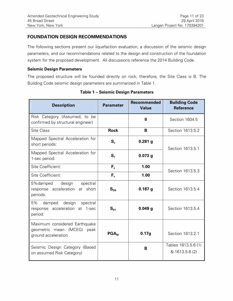
Seismic Design Parameters
The proposed structure will be founded directly on rock; therefore, the Site Class is B. The
Building Code seismic design parameters are summarized in Table 1.
Table 1 – Seismic Design Parameters
Description Parameter Recommended
Value
Building Code
Reference
Risk Category (Assumed; to be
confirmed by structural engineer) II Section 1604.5
Site Class Rock B Section 1613.5.2
Mapped Spectral Acceleration for
short periods: Ss 0.281 g
Section 1613.5.1 Mapped Spectral Acceleration for
1?sec period: S1 0.073 g
Site Coefficient: Fa 1.00 Section 1613.5.3
Site Coefficient: Fv 1.00
5%damped design spectral
response acceleration at short
periods:
SDS 0.187 g Section 1613.5.4
5% damped design spectral
response acceleration at 1?sec
period:
SD1 0.049 g Section 1613.5.4
Maximum considered Earthquake
geometric mean (MCEG) peak
ground acceleration
PGAM
0.17g
Section 1813.2.1
Seismic Design Category (Based
on assumed Risk Category) B
Tables 1613.5.6 (1)
& 1613.5.6 (2)

Amended Geotechnical Engineering Study
45 Broad Street
New York, New York
Page 12 of 23
29 April 2016
Langan Project No. 170394201
12
Based on the design spectral accelerations in Table 1 and the anticipated structural
occupancy/risk category of the structure (identified as Structural Occupancy/Risk Category II)
and in accordance with the Building Code, we have estimated that the design will be subject to
the requirements of Seismic Design Category B. The Structural Occupancy/Risk Category must
be confirmed by the architect and structural engineer.
Liquefaction Evaluation
The Building Code requires an evaluation of the liquefaction potential of noncohesive soil and
cohesive soil with plasticity index 20 or less below the groundwater table and up to 50 feet
below the ground surface. In accordance with the Building Code screening process for
liquefaction, the SPT N60 values from the borings are plotted versus depth on the Liquefaction
Assessment Diagram, presented as Figure 9. This plot shows a significant amount of soil in the
“Liquefaction Probable” zone.
The proposed construction involves excavation and removal of all soil to support the structure
directly on rock. Therefore, the risk of liquefaction is mitigated and a site?specific study is not
required. If the development plan changes and excavation and removal of all liquefiable soil is
no longer considered, the design team should address this change and re?evaluate the site
classification and soil liquefaction potential.
Foundation System
We recommend the building be supported by a mat foundation bearing on bedrock. The
recommended allowable rock bearing capacity is 40 tsf (Building Class 1b bock). The top of
rock was encountered at depths of about 38 to 49 feet below the existing site grades and
generally dips north to south. The corresponding top or rock elevations range from about el ?28
to el ?40. The bottom of a 9 to 12?foot?thick mat foundation as shown on preliminary design
drawings prepared by WSP, will be at about el ?29.5 to el ?33. Therefore, the bottom of the
proposed mat will not bear directly on rock at the majority of the site.
Wherever Building Class 1b rock is not encountered at the bottom of mat foundation elevation,
all soil and decomposed rock should be excavated to the top of Building Class 1b rock and
backfilled with 4,000 psi concrete fill. All rock bearing surfaces should have a maximum 10?
percent slope as required by the Building Code. Otherwise, horizontal benches 10 feet long
and wide, with vertical faces, should be created to satisfy the maximum slope requirement.
Because the difference in the bottom of the mat elevation and the estimated top of rock can be
as much as 8 feet or more, WSP should evaluate whether the concrete fill should be reinforced.

Amended Geotechnical Engineering Study
45 Broad Street
New York, New York
Page 13 of 23
29 April 2016
Langan Project No. 170394201
13
For initial design development, we recommend an average modulus of subgrade reaction of
1,500 psi/inch for Class 1b rock. The mat foundation design should be compatible with half and
twice of this value. The subgrade modulus must be iterated until the geotechnical model and
the structural model (which approximates the subgrade response via Winkler springs) converge
(i.e., the spring value must be iterated until the settlement predicted by the geotechnical model
matches that predicted by the structural model).
Foundation Settlement
The settlement of foundations is a function of the structural loads and are dependent on the
layout of columns and shear walls and stiffness of the foundation. For the proposed building
loads, we anticipate that the total and differential foundation settlements below the thick
foundation mat will be ¾ inch or less.
Lateral Resistance
For a mat bearing directly on rock, lateral loads can be resisted by friction on the bottom of the
mat. We recommend an ultimate frictional coefficient of 0.70 for mass concrete poured on
clean sound rock. Where concrete fill underlies the mat foundation, WSP should confirm that
the concrete fill?to?foundation concrete?to?rock interfaces can resist the proposed lateral
loading. If additional resistance is needed, shear keys may be embedded into rock or concrete.
We should be contacted to evaluate passive pressure if needed.
Rigid Perimeter Excavation Support
Below grade construction will require excavating to the top or rock or about 38 to 49 feet below
the existing grades (about el ?28 to el ?40). To provide excavation support and temporary
groundwater cut?off we recommend installing a rigid, continuous secant pile wall system on the
south, east, and west foundation perimeter. The secant pile walls will abut the foundation wall
of 41 Broad Street, which extends into the bedrock according to historic construction plans.
The secant pile wall installation begins with the construction of a guide wall at the ground
surface. The guide wall ensures that the position, alignment and required overlap of
subsequent secant piles are maintained. After the guide wall is formed, the primary piles
(every other pile location) are installed by advancing steel casing to top of rock and continuing
the rock socket to the design depth. The casing is then withdrawn as the pile is
grouted. Secondary piles are then drilled in between such that they overlap with the primary
piles. Reinforcing steel is added to the secondary piles based on the structural loading and

Amended Geotechnical Engineering Study
45 Broad Street
New York, New York
Page 14 of 23
29 April 2016
Langan Project No. 170394201
14
excavation support requirements. These systems are relatively stiff soil retention systems,
necessary to limit wall deflection and movement of adjacent structures, and assist in
groundwater control. To accommodate access of the drilling equipment close to the property
line, the edge of casing is positioned at least 12 inches from the face of adjacent buildings. The
contractor should note that obstructions such as remnant slabs and foundations including piles
and pile caps exist within and below the fill and should be removed prior to or bypassed during
the installation of the perimeter excavation support.
In addition to serving as temporary excavation support and water cut?off, the secant pile wall
can serve as the permanent foundation wall and carry part of the foundation loads according to
the foundation design. The structural loads on the secant pile wall were not available at the
time of this report. If the secant piles are used to rest tension capacity, they must also be
evaluated for global stability. In addition, the top level of the secant pile wall must be
coordinated with the structural engineer to account for the continuous ring beam.
For top?down construction, lateral bracing is provided by the ground and cellar floors slabs,
which are constructed as the excavation progresses. The Owner and design team are
considering creating additional headroom during construction by constructing one of the cellar
slabs after the foundation construction is complete; therefore additional temporary lateral
support will be necessary at the bypassed slab elevation. Lateral support could consist of
tiebacks on the east and west (below the NYCT tunnel influence line) and rakers or buttresses
(additional secant piles perpendicular to the perimeter walls).
The NYC Department of buildings (DOB) requires that project?specific excavation support
drawings be prepared as part of the new?building submission. The project?specific plans must
be fully developed, in conjunction with developed structural building plans, to be reviewed and
approved by DOB so that a construction permit for the new building (or foundations) can be
issued. Excavation support plans will also need to be reviewed by the NYCT for potential
impacts on the adjacent subway structures.
Permanent Rock Anchors
Permanent post?tensioned tie?downs anchored into bedrock will be required to resist uplift
forces resulting from wind, buoyant, and seismic loads. We recommend using double
corrosion?protected Grade 150 threaded bars meeting ASTM A?722 requirements or Grade 270
strand tendons meeting ASTM A?416 requirements for reinforcement steel. Double corrosion

Amended Geotechnical Engineering Study
45 Broad Street
New York, New York
Page 15 of 23
29 April 2016
Langan Project No. 170394201
15
protection should consist of PVC sheathing and grout encapsulation around the anchor bar or
tendons. The anchor bar diameter should not exceed 3 inches; if higher capacity is required,
strand anchors should be used. The anchor bond length should be proportioned using an
allowable peripheral shear resistance in uplift of 100 psi. The free stress (un?bonded) length
should be a minimum of 10 feet long, but additional length may be required for group effects
and global uplift stability.
The free?stressing length of reinforcement should be proportioned such that the dead weight
and tensile strength of the engaged rock mass is greater than the individual anchor load or the
sum of the group anchor loads. Group and global stability analysis must be performed by
Langan during design development. The free length of adjacent anchors can be alternated in a
staggered pattern, if required by the group analysis. Table No. 2 and Table No. 3 present the
estimated design capacity with corresponding bond lengths for both threaded bars and strand
tendon options.
Table 2 – Threaded Bar Rock Anchor Capacities
Design Uplift
Load
(kips)
Threaded Bar
Diameter
(inch)
Threaded
Bar Grade
Min. Drill
Hole
Diameter
(inch)
Min. Free
Length1
(ft)
Min. Bond
Length2
(ft)
110 1?1/4 150 5 10 10
615 3 150 7 10 25
1 The free stressing length will be defined by the global stability and group effect analysis
2 This table represents minimum lengths for single anchors. Group effects must be analyzed during DD phase and may require
longer anchors.

Amended Geotechnical Engineering Study
45 Broad Street
New York, New York
Page 16 of 23
29 April 2016
Langan Project No. 170394201
16
Table 3 – Strand Tendon Rock Anchor Capacities
Design Uplift
Load
(kips)
No. of
Strand
Tendons
Strand Tendon
Cross Sectional
Area (sq?inch)
Strand
Tendon
Grade
Min. Drill
Hole
Diameter
(inch)
Min. Free
Length1
(ft)
Min. Bond
Length2
(ft)
110 4 0.868 270 5 10 10
615 18 3.906 270 7 10 25
1 The free stressing length will be defined by the global stability and group effect analysis
2 This table represents minimum lengths for single anchors. Group effects must be analyzed during DD phase and may require
longer anchors.
A minimum of 10 anchors or two percent of the tie?down anchors (whichever is greater) should
be performance?tested (creep) to 133% of their design loads in accordance with Post?
Tensioning Institute (PTI) standards. The remaining anchors should be proof tested to 133%
their design load per PTI standards. Lift?off testing should be performed to all anchors.
Successfully tested anchors should be locked off at a load exceeding the sum of the design
load, seating loss, and long?term losses.
Pressure Slabs
The lowest floor level will extend below groundwater and should be designed as a pressure
slab. We recommend that the pressure slabs be designed assuming hydrostatic uplift
corresponding to the design groundwater el 12 (BFE + 1ft). Where possible, pressure slabs
should be keyed into the foundation walls and should be cast with integral water stops (PVC
“dumbbells” and post construction grout tubes). Pressure slabs should be waterproofed
according to the recommendations presented herein.
Permanent Groundwater Control
This section describes our recommendations for permanent groundwater control at the site.
Design Groundwater Level
During the 2007 subsurface exploration, the static groundwater was observed at about 18 to
20 feet below existing grade (about el ?8 to el ?10). During the 2016 subsurface exploration, the

Amended Geotechnical Engineering Study
45 Broad Street
New York, New York
Page 17 of 23
29 April 2016
Langan Project No. 170394201
17
static groundwater was observed at about 13.5 feet below existing grade (about el ?3.5). This
fluctuation could be related to seasonal variations, nearby construction or pumping activities.
Because the site is partially located within the Flood Zone AE, the foundation walls, ground
level, and below?ground slabs should be flood?proofed and designed to resist hydrostatic
pressure for groundwater rising to el 12. This Design Flood Elevation (DFE) corresponds to the
base flood elevation of el 11 (BFE) plus 1?foot freeboard as per Chapter G5 Table 6.1 of the
Building Code.
Foundation Waterproofing
To limit water seepage we recommend that the foundation raft and the perimeter secant pile
wall be fully waterproofed to at least the design flood elevation (DFE). We recommend
installing a membrane?type, positive?side waterproofing (installation on outside of structure).
For horizontal applications, the waterproofing membrane should be installed on a two?inch?
minimum concrete working surface (mud?slab), which will create a uniform substrate. For one?
face wall vertical applications (conventional foundation wall and pit walls), plywood or other
acceptable flat surfaces should be used to secure the waterproofing membrane. The
membrane should be protected against damage during rebar placement, concrete placement,
and general construction traffic.
Groundwater can be expected to seep through the joints in the secant pile wall. One scheme
to accommodate the water leakage is to create a cavity wall using masonry block. The water is
collected behind the partition walls via a series of scupper drains and directed to the lowest
cellar level. The water is then ejected and discharged into the city sewer system.
An alternate scheme is to waterproof the inside face of the secant pile wall. This can be
accomplished by installing a waterproofing membrane on the secant pile wall and casting an
interior liner wall. Prior to the membrane application the secant wall surface should be purged
and leveled. A concrete facing wall would then be cast against the secant piles to provide the
necessary bond to the waterproofing and to hold the membrane in place. The minimum wall
thickness is 4 inches (or as otherwise recommended by the waterproofing manufacturer) as
needed for structural integrity. Special waterproofing details will need to be developed for
locations of the secant pile wall – intermediate slabs interface and at the bracing locations. For
the horizontal and vertical applications we recommend using Preprufe products by W.R. Grace
or other equivalent. As a supplementary measure, waterproofing concrete admixtures such as

Amended Geotechnical Engineering Study
45 Broad Street
New York, New York
Page 18 of 23
29 April 2016
Langan Project No. 170394201
18
Hycrete’s products can be added to the secant pile grout mix (for water control and corrosion
protection) and the liner wall grout mix.
We recommend that warranties are obtained from the manufacturers and installers to cover
materials and workmanship. Material and system compatibility needs to be confirmed if
products from multiple manufacturers are selected. Only certified installers should be used to
perform the work. Detailed oversight should be performed and a representative of the
manufacturer should perform a final inspection of the waterproofing prior to concrete pours.
Depending on the use of the cellar space, installing a secondary control system may be
warranted. For this purpose the following secondary measures can also be considered.
1. Install a second mud slab on top of the installed horizontal waterproofing membrane.
This mud slab would protect the installed waterproofing from construction traffic during
placement for the steel reinforcement.
2. Use a waterproofing additive in the foundation concrete. Addatives typically react with
water to block pours and small cracks.
3. Install a connection layer and concrete slab over the mat slab. The draining layer can be
gravel with collection pipes or a heavy duty prefabricated drainage board. This system
will collect groundwater (that could intrude through damaged waterproofing) and guide it
to a drain system.
Permanent Below@Grade Walls
Permanent below?grade walls including perimeter foundation and elevator pit walls should be
designed to resist lateral loadings from static earth pressure, water pressure, and vertical
surcharge. Backfill should not be placed against below?grade walls until the concrete has
reached its 28?day compressive design strength and after adequate lateral bracing has been
provided to prevent rotation of the wall, or as otherwise directed by the structural engineer. We
recommend the following design parameters in Table 3 and subsequent paragraphs.

Amended Geotechnical Engineering Study
45 Broad Street
New York, New York
Page 19 of 23
29 April 2016
Langan Project No. 170394201
19
Table 3 – Horizontal Earth Pressure Parameters
Layer Unit Weight
Above WT (pcf)
Effective Unit
Weight Below
WT (pcf)
At Rest Earth
Pressure
Coefficient Ko
Fill [Class 7] 120 63 .50
Silt and Clay
[Class 5b, 4c, 6] 110 57 .60
Decomposed
Rock [Class 1d] 135 72 .35
• Hydrostatic pressures should be added as a triangular pressure distribution having an
equivalent fluid weight of 62.4 pounds per square foot per foot of depth below the
design groundwater level.
Surcharge loads should be considered in the design of below?grade walls. The walls should be
designed for an additional uniform pressure distribution equal to 0.50 times the anticipated
surcharge load. We recommend the following minimum surcharges be considered:
• Surficial traffic loads should be considered for the west perimeter walls (along Broad
Street). We recommend a surcharge load of 300 psf for the street side walls to account
for large trucks and emergency vehicles.
• Surficial loads should be considered for the east perimeter walls (along hammerhead).
We recommend a surcharge of 100 psf for these walls.
• Construction surcharge loads should be considered along the west and east perimeter
walls if they exceed the recommended values above.
• Walls must also be designed for surcharge loads from adjacent structures where the
walls extend below the area of influence of the adjacent foundations. We understand
41 Broad Street is founded on rock, and 55 Broad Street is founded on piles such that
only the surcharge from the neighboring slab needs to be considered.

Amended Geotechnical Engineering Study
45 Broad Street
New York, New York
Page 20 of 23
29 April 2016
Langan Project No. 170394201
20
GEOTECHNICAL CONSTRUCTION RECOMMENDATIONS
Our recommendations for excavation, subgrade preparation, temporary groundwater control,
and pre?construction activities and construction monitoring are provided below.
Excavation
Site excavation within the fill and underlying silt and clay can be performed using conventional
earth?moving equipment (e.g., backhoes, excavators, dozers, etc.). All excavations should be
conducted in accordance with all OSHA requirements including, but not limited to, temporary
shoring, trench boxes, and proper benching. Obstructions such as old foundations, slabs, pile
caps and piles, and demolition debris should be expected and may require heavy demolition
equipment to remove.
Note that obstructions such as remnant slabs and foundations including piles and pile caps exist
within and below the fill. Specifically, the remnant cellar slab was encountered about 12 feet
below existing grade. The contractor should be prepared to demolish and excavate through the
existing slab and all obstructions, and remove the existing pile caps, piles, and slabs.
An alternative method to perform the foundation construction would be the “top?down”
construction method. In general terms this option involves construction of the ground and
cellar floor levels as the excavation progresses. Top?down construction begins with installation
of exterior walls and load bearing elements to support subsequent floor slabs. The ground floor
is then cast. The excavation is performed below the cast slab to the next slab level, with
excavation spoils removed through shafts and access openings in the slabs. The process is
repeated to the final mat level.
Subgrade Preparation for Foundation Mat on Rock
The foundation mat bearing surface should be level and clear of debris, standing or frozen
water, and other deleterious materials. All rock bearing surfaces should have a maximum 10?
percent slope as required by the Building Code. Otherwise, horizontal benches at least 10 feet
long and wide with vertical faces should be created to satisfy the maximum slope requirement.
Compressed air should be used to clean all rock surfaces. Rock, joints, foliation, and local
zones of weathered or fractured rock may require locally deepening the excavations further into
rock. The Building Code requires that all rock subgrade be inspected by Professional Engineer
to verify the quality of the bedrock before installing reinforcing steel and concreting. The rock

Amended Geotechnical Engineering Study
45 Broad Street
New York, New York
Page 21 of 23
29 April 2016
Langan Project No. 170394201
21
subgrade must be inspected to verify bearing capacity and that foundations have been
adequately cleaned and prepared.
Temporary Groundwater Control
Groundwater was encountered in the 2016 investigation at 13.5 feet below grade. The
proposed deep excavation will require dewatering. The proposed SOE system using secant
piles and tangent piles will provide groundwater cutoff such that the interior of the excavation
can be locally dewatered. Collection of rainwater runoff will also be needed during the
excavation and subgrade preparation work. Water runoff should be controlled with the use of
gravel?lined collection trenches or pits and submersible pumps. Care should be taken to ensure
that drainage is provided during all phases of excavation work so as to limit the disturbance of
the subgrade materials and provide a workable surface. Any necessary environmental pre?
treatment of groundwater should be coordinated with the applicable environmental regulations
for the site. A DEP discharge permit will need to be furnished to discharge groundwater into
the DEP combined sewer. It is the contractor’s responsibility to estimate the daily groundwater
discharge volume and to furnish all paperwork for the permit application.
Preconstruction Conditions Survey and Monitoring During Construction
A preconstruction?conditions survey report should be prepared for the adjacent buildings and
the existing NYCT subway tunnel adjacent to the site. We recommend that a monitoring
program be developed to observe the response of the existing buildings and subway tunnel
adjacent to the site during foundation construction activities (i.e., excavation, SOE installation,
bracing, etc.). According to our past discussions with NYCT, this program could consist of
monitoring horizontal and vertical movements by optical surveying and inclinometers, and
vibration monitoring using seismographs. The NYCT typically requires that the vibration
monitoring data is collected manually, or at least has on site observation of an automated
system.
Construction Documents and Quality Control
Design specifications and drawings should incorporate our recommendations to ensure that
subsurface conditions and other geotechnical issues at the site are adequately addressed in
construction documents. Langan should assist the design team in preparing specification
sections related to geotechnical issues such as support of excavation, foundations, backfill, and
excavation support. Langan should also review foundation design drawings and details, and all
contractor submissions and construction procedures related to geotechnical work.

Amended Geotechnical Engineering Study
45 Broad Street
New York, New York
Page 22 of 23
29 April 2016
Langan Project No. 170394201
22
Geotechnical assessment and design is an ongoing process as additional information becomes
available, including during construction. A geotechnical engineer familiar with the site
subsurface conditions and design intent should perform the quality assurance observations and
testing of geotechnical?related work during construction. According to the Building Code,
construction of foundations (i.e., earthwork, subgrade preparation, etc.) and support of
excavation require special inspection by a Professional Engineer licensed in the state of New
York.
Owner and Contractor Obligations
Construction activities that alter the existing ground conditions such as excavation, fill
placement, foundation construction, ground improvement, pile driving/drilling, dewatering, etc.
can induce stresses, vibrations and movements on nearby structures. The Owner and all
Contractors must ensure that these impacts will not adversely affect the performance of the
structures and take adequate measures to protect the existing structures during construction.
Unless otherwise agreed to by Langan in writing, by using this report, the owner agrees to the
following:
1) That Langan will not be held responsible for damage to adjacent structures caused by the
actions of contractors involved in the project;
2) To have Langan added to the Foundation Contractor’s General Liability insurance as an
additional insured;
3) To require the Foundation Contractor to defend, indemnify and hold harmless the Owner and
Langan against all claims related to damage to adjacent structures or properties
LIMITATIONS
The conclusions and recommendations provided in this report are based on subsurface
conditions inferred from a limited number of borings, as well as information provided by
Madison 45 Broad Development LLC, February 2016 concept design drawings and sketches
provided by CetraRuddy, and subsequent discussions with the project team.
Recommendations provided are dependent upon one another and no recommendation should
be followed independent of the others.
Any proposed changes in structures or their locations should be brought to Langan’s attention
as soon as possible so that we can determine whether such changes affect our
recommendations. Information on subsurface strata and groundwater levels shown on the logs

Amended Geotechnical Engineering Study
45 Broad Street
New York, New York
Page 23 of 23
29 April 2016
Langan Project No. 170394201
23
represent conditions encountered only at the locations indicated and at the time of
investigation. If different conditions are encountered during construction, they should
immediately be brought to Langan’s attention for evaluation, as they may affect our
recommendations.
This report has been prepared for 45 Broad Street, New York, New York, to assist the owner,
architect, and structural engineer in the design process and is only applicable to the design of
the specific project identified. The information in this report cannot be utilized or depended on
by engineers or contractors who are involved in evaluations or designs of facilities (including
underpinning, grouting, stabilization, etc.) on adjacent properties, which are beyond the limits of
that which is the specific subject of this report.
Environmental issues (such as potentially contaminated soil and groundwater) are outside the
scope of this study and should be addressed in a separate study.
\\Langan.com\data\NY\data2\170394201\Office Data\Reports\Geotechnical\Updated Geotechnical Report\2016?03?03 Geotechnical Engineering Study.docx

P1105 – 45 Broad Street
Structural Peer Review Report – Foundation
24 February 2017
Leslie E. Robertson Associates, RLLP LERA Consulting Structural Engineers
Appendix E SOE Plan Drawing


P1105 – 45 Broad Street
Structural Peer Review Report – Foundation
24 February 2017
Leslie E. Robertson Associates, RLLP LERA Consulting Structural Engineers
Appendix F Caisson and Secant Pile Wall Capacity
Summary Tables from WSP
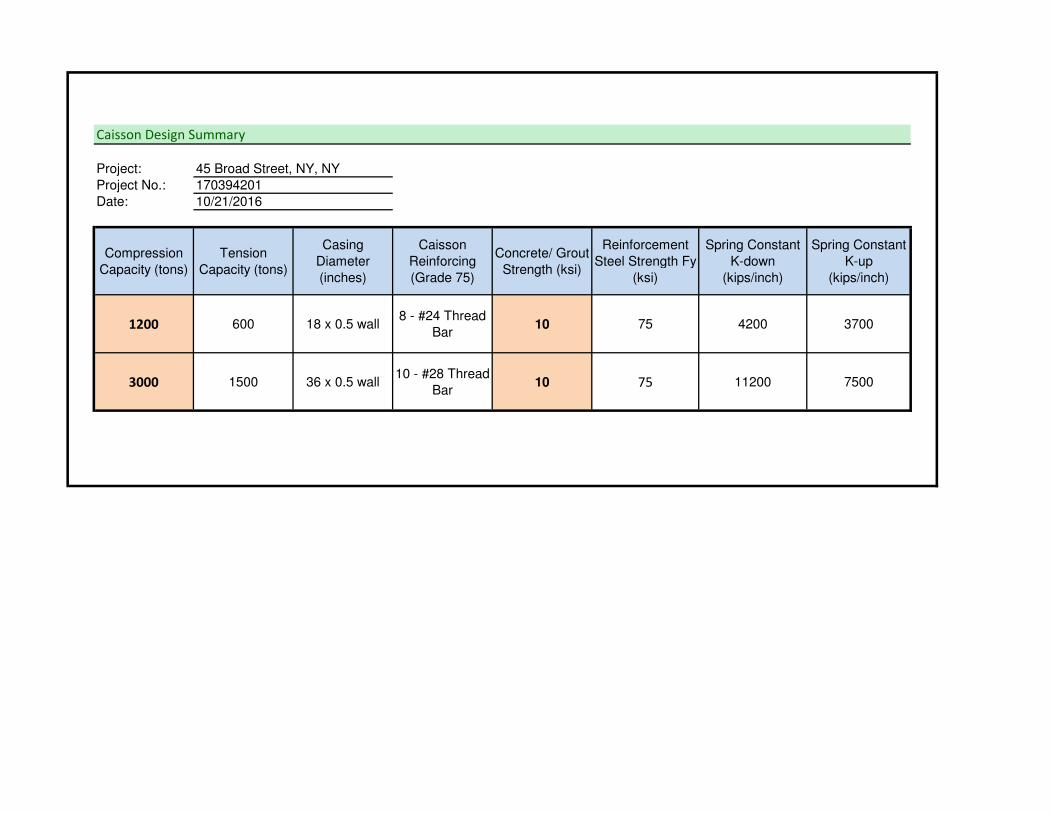
Caisson Design Summary
Project: 45 Broad Street, NY, NY
Project No.: 170394201
Date: 10/21/2016
Compression
Capacity (tons)
Tension
Capacity (tons)
Casing
Diameter
(inches)
Caisson
Reinforcing
(Grade 75)
Concrete/ Grout
Strength (ksi)
Reinforcement
Steel Strength Fy
(ksi)
Spring Constant
K-down
(kips/inch)
Spring Constant
K-up
(kips/inch)
1200 600 18 x 0.5 wall8 - #24 Thread
Bar10 75 4200 3700
3000 1500 36 x 0.5 wall10 - #28 Thread
Bar10 75 11200 7500
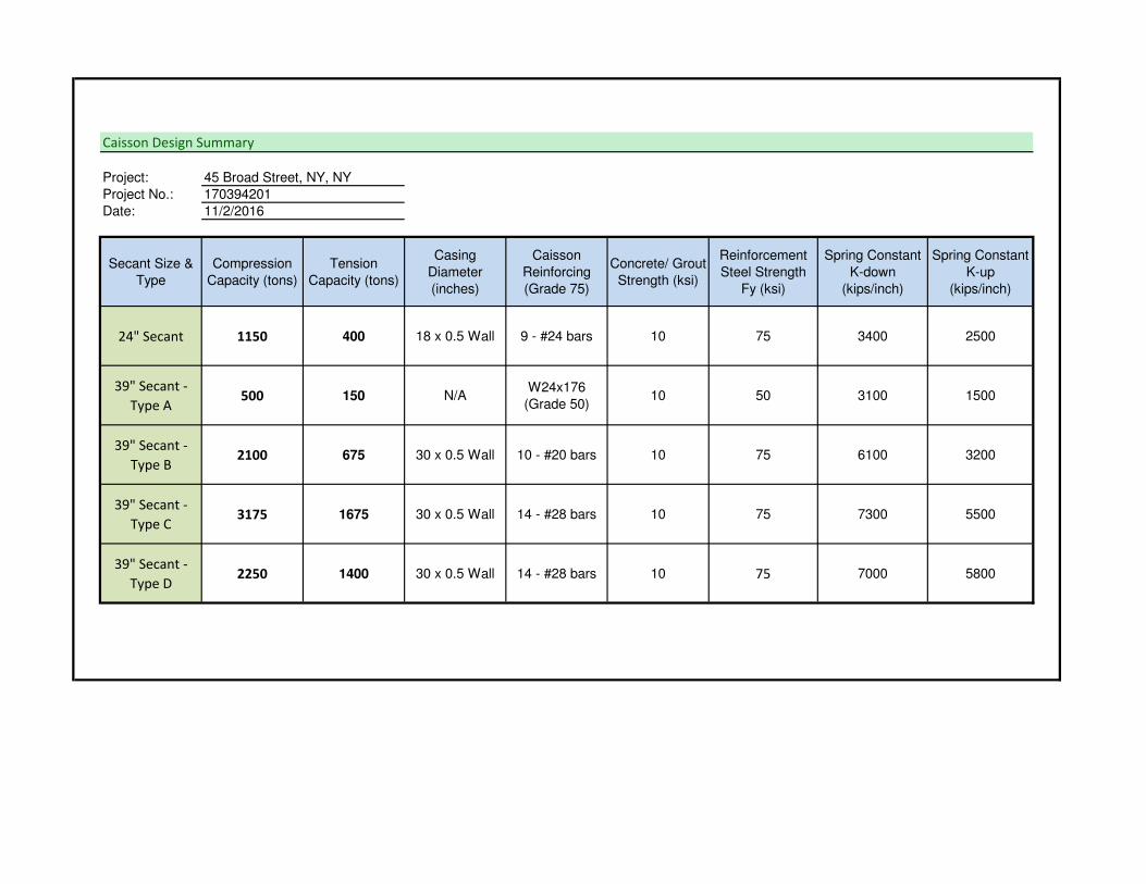
Caisson Design Summary
Project: 45 Broad Street, NY, NY
Project No.: 170394201
Date: 11/2/2016
Secant Size &
Type
Compression
Capacity (tons)
Tension
Capacity (tons)
Casing
Diameter
(inches)
Caisson
Reinforcing
(Grade 75)
Concrete/ Grout
Strength (ksi)
Reinforcement
Steel Strength
Fy (ksi)
Spring Constant
K-down
(kips/inch)
Spring Constant
K-up
(kips/inch)
24" Secant 1150 400 18 x 0.5 Wall 9 - #24 bars 10 75 3400 2500
39" Secant -
Type A500 150 N/A
W24x176
(Grade 50)10 50 3100 1500
39" Secant -
Type B2100 675 30 x 0.5 Wall 10 - #20 bars 10 75 6100 3200
39" Secant -
Type C3175 1675 30 x 0.5 Wall 14 - #28 bars 10 75 7300 5500
39" Secant -
Type D2250 1400 30 x 0.5 Wall 14 - #28 bars 10 75 7000 5800