structural orientation and anisotropy in biological
TRANSCRIPT
www.afm-journal.de
© 2020 WILEY-VCH Verlag GmbH & Co. KGaA, Weinheim1908121 (1 of 17)
Progress rePort
Structural Orientation and Anisotropy in Biological Materials: Functional Designs and Mechanics
Zengqian Liu,* Zhefeng Zhang,* and Robert O. Ritchie*
Biological materials exhibit anisotropic characteristics because of the anisometric nature of their constituents and their preferred alignment within interfacial matrices. The regulation of structural orientations is the basis for material designs in nature and may offer inspiration for man-made materials. Here, how structural orientation and anisotropy are designed into biological materials to achieve diverse functionalities is revisited. The orientation dependencies of differing mechanical properties are introduced based on a 2D composite model with wood and bone as examples; as such, anisotropic architectures and their roles in property optimization in biological systems are elucidated. Biological structural orientations are designed to achieve extrinsic toughening via complicated cracking paths, robust and releasable adhesion from anisotropic contact, programmable dynamic response by controlled expansion, enhanced contact damage resistance from varying orientations, and simultaneous optimization of multiple properties by adaptive structural reorientation. The underlying mechanics and material-design principles that could be reproduced in man-made systems are highlighted. Finally, the potential and challenges in developing a better understanding to implement such natural designs of structural orientation and anisotropy are discussed in light of current advances. The translation of these biological design principles can promote the creation of new synthetic materials with unprecedented properties and functionalities.
DOI: 10.1002/adfm.201908121
Prof. Z. Q. Liu, Prof. Z. F. ZhangLaboratory of Fatigue and Fracture for MaterialsInstitute of Metal ResearchChinese Academy of SciencesShenyang 110016, ChinaE-mail: [email protected]; [email protected]. Z. Q. Liu, Prof. Z. F. ZhangSchool of Materials Science and EngineeringUniversity of Science and Technology of ChinaHefei 230026, ChinaProf. R. O. RitchieDepartment of Materials Science and EngineeringUniversity of California BerkeleyBerkeley, CA 94720, USAE-mail: [email protected]
The ORCID identification number(s) for the author(s) of this article can be found under https://doi.org/10.1002/adfm.201908121.
The majority of engineering materials have been developed based on significant chemical complexity, which is not acces-sible to natural organisms; in contrast, the large varieties of biological materials are created from a highly limited pal-ette of substances.[1–4] By contrast, it is mainly through the perfection of their architectures that the materials in nature evolve to fulfill specific demands.[4–9] Such architectural design presents an exceptional efficiency in property opti-mization as biological materials often significantly surpass their constituents and sometimes even outperform engineering materials.[10,11] Given the enormous diver-sity of biological systems, natural materials usually exhibit some common character-istics of design underlying their archi-tectures, especially in answering similar environmental challenges. This is well rep-resented, for example, by wood and bone; both materials feature a fibrous structure at the nanoscale with fibers of varying orientations arranged in a lamellar fashion despite their distinctly different chemical compositions.[8,12–17] Natural materials have long been recognized as a source
of inspiration for new engineering materials with their archi-tectures being increasingly replicated in man-made systems to obtain improved performance.[1–9,18–28] To this end, it is of signifi-cance to extract the common principles of architectural designs among diverse biological materials from the viewpoint of mate-rials science and mechanics—it is essentially these principles that need to be reproduced and that we should learn from nature.
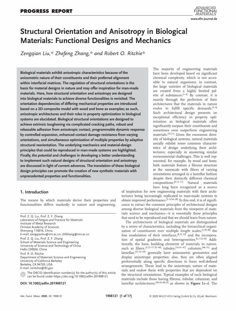
The architectures of biological materials are distinguished by a series of characteristics, including the hierarchical organi-zation of constituents over multiple length scales,[5,29,30] the fine modulation of their interfaces,[8,31,32] and the incorpora-tion of spatial gradients and heterogeneities.[6,7,33,34] Addi-tionally, the basic building elements of materials in nature, such as fibers,[2,12–17,35–40] tubules,[14,41–47] columns,[48–51] and lamellae,[37,52–59] generally have anisometric geometries and display anisotropic properties; also, they are often aligned preferentially along specific directions to form well-defined arrangements. These lead to the anisotropic nature of mate-rials and endow them with properties that are dependent on the structural orientations. Typical examples of such biological materials include those having fibrous, tubular, columnar, and lamellar architectures,[40,44,48,52] as shown in Figure 1a–d. The
1. Introduction
The means by which materials derive their properties and functionalities differs markedly in nature and engineering.
Adv. Funct. Mater. 2020, 30, 1908121
www.afm-journal.dewww.advancedsciencenews.com
1908121 (2 of 17) © 2020 WILEY-VCH Verlag GmbH & Co. KGaA, Weinheim
anisotropy is widespread at differing levels of structural hier-archy. Taking wood for example, the nanoscale architecture of wood cell walls is characterized by cellulous microfibrils embedded within a compliant matrix of hemicelluloses and lignin.[12,13,16,60–66] At a larger length scale, the wood cells are preferentially aligned along the growth direction and com-bined together through interfaces that are weaker than the cell walls.[12,13,16,65] Another case in point is cortical bone where unidirectional mineralized collagen fibrils are present in the noncollagenous matrix within each lamella of osteons;[14,53,66–70] the osteons are further assembled in the bone along its length direction.[14,67–69] The structural anisotropy provides a large space for the architectural design of materials to obtain desired performance. A prime advantage is to strengthen the mechan-ical properties along required directions considering that the applied stress/strain conditions are rarely equiaxed in prac-tice. This is represented by the vertical alignment of nanoscale hydroxyapatite crystals in mammal tooth enamels, which helps maximize the stiffness against masticatory loads.[47,71–76] Addi-tionally, the anisotropic structuring gives opportunities for deriving unique functionalities in biological systems, such as robust but easily releasable adhesion and spontaneous adapta-tion to external stimuli.[77–83]
Many engineering materials are also made anisotropic, e.g., by the development of rolling textures in metals;[84–86] never-theless, their architectures are invariably far less designed with lower levels of complexity and delicacy as compared to biological systems. A deeper understanding about the design principles of structural orientation and anisotropy in biological materials can certainly promote a better reproduction of them and inspire new solutions for engineering problems. However, this issue remains largely unexplored and seems have attracted less atten-tion as compared to other well-known characteristics like struc-tural hierarchy.[1–9,29–32] For example, it is only until very recently that the adaptive structural reorientation of biological materials during deformation has been identified as a strategy to achieve a simultaneous enhancement of the combinations of mechan-ical properties,[87] rather than merely a passive response to allow for flexibility. Moreover, the artificial implementation of these natural principles is even further away in view of the limited potency of traditional processing techniques in manipulating the micro/nanoscale structural orientations of materials.
2. Mechanical Role of Interfaces in Biological Materials
There are abundant interfaces between constituents in bio-logical materials at each level of hierarchy in their structure. These interfaces are one of the basic structural features for orientation and anisotropy, particularly in systems where the anisotropy is determined by the preferred alignment of con-stituents within the interfacial matrices. The interfaces gen-erally demonstrate markedly differing chemical attributes and mechanical properties for different species. Neverthe-less, many of them can be seen as similar among biological materials from the perspective of fundamental mechanics as they usually exhibit common characteristics, especially when compared to the building constituents. The structure and
Zengqian Liu is a Professor in the Institute of Metal Research, Chinese Academy of Sciences (IMR, CAS). He received his Ph.D. degree from Beihang University in 2013. From 2013 to 2015, he worked with Prof. Zhefeng Zhang at IMR, CAS as a T. S. Ke postdoctoral research fellow. He joined the IMR, CAS in 2015. From 2015
to 2017, he worked with Prof. Robert O. Ritchie at the University of California, Berkeley as a postdoctoral research associate. He works in the field of biological and bioin-spired structures and materials with a special focus on their mechanical properties.
Zhefeng Zhang is a Professor in the Institute of Metal Research, Chinese Academy of Sciences (IMR, CAS). After receiving his Ph.D. degree from IMR in 1998, he joined the IMR as a research associate. From 2000 to 2001, he worked at the National Institute of Advanced Industrial Science and Technology, Japan as a JSPS
fellow. From 2001 to 2003, he worked with Prof. L. Schultz and Prof. J. Eckert at the Institute for Metallic Materials, IFW-Dresden, Germany. He assumed his present position in 2004. His research focuses on the mechanical proper-ties, specifically about the fatigue and fracture behavior, of materials.
Robert O. Ritchie is the Chua Distinguished Professor of Engineering in the Materials Science and Engineering Department at the University of California Berkeley, and Faculty Senior Scientist at the Lawrence Berkeley National Laboratory. He holds M.A., Ph.D., and Sc.D. degrees in physics/materials science from Cambridge,
is a member of the National Academy of Engineering in the U.S., and a Fellow of the Royal Society in London. He is known for his research on the fracture of materials, with current interests focused on bioin-spired materials, the degradation of bone, and fracture in multicomponent alloys.
Adv. Funct. Mater. 2020, 30, 1908121
www.afm-journal.dewww.advancedsciencenews.com
1908121 (3 of 17) © 2020 WILEY-VCH Verlag GmbH & Co. KGaA, Weinheim
mechanics of interfaces in biological materials, as represented by the nanoscale interfibrillar matrices of wood and bone, and their roles in optimizing material performance have been elu-cidated in recent reviews.[1,4,8,31]
Here we emphasize several key properties of interfacial mate-rials that are widespread among different biological systems: (i) interfacial matrices are generally more compliant and prone to deform than the constituents; (ii) they usually exhibit outstanding shearing ability or extensibility to withstand both viscoelastic and plastic deformation; (iii) interfaces are typically weaker and less resistant to cracking than constituents; (iv) the majority of interfacial materials are more hygroscopic and responsive to environmental stimuli, e.g., hydration or dehydration, than constituents. These characteristics are the basis for most of the anisotropic designs in biological materials in developing their functionalities. For example, the easy propagation of cracks along interfaces is critical for rendering the toughening effect through the complexity of structural orientations.[88–92] Addition-ally, the good deformability of interfacial matrices plays a key role in allowing for the in situ reorientation of constituents during deformation,[15,58] thereby offering an effective approach toward simultaneous improvement in different mechanical properties.[87]
3. Dependency of Mechanical Properties on Structural Orientation
Most of biological materials can be seen as composites com-prising at least two phases with distinct mechanical properties,
such as stiffness or ductility. The structural motifs that encom-pass anisotropy can be described using a 2D elementary com-posite model,[34,60,87,93–96] as illustrated in Figure 1e, where the stiff (or strong) and soft (or weak) phases are alternatively organized. The stiff phase represents the substructural con-stituents of the composite, whereas the soft phase refers to the compliant matrix or interfaces between constituents. The two phases per se are considered to be isotropic and homogeneous and exhibit an ideally tight bonding state for connection, i.e., the strain is continuous at their boundaries. In this scenario, the anisotropic nature of the composite rests exclusively on the alignment of its constituents with respect to the external load. The structural orientation can thus be depicted using the off-axis angle between the loading axis and the stiff direction of composite, i.e., the longitudinal axis of constituents.
The current 2D model is consistent with the anisotropic structure of most of the biological materials that are principally subject to in-plane stress/strain states, especially those having relatively thin flat shapes. However, it fails to fully capture the 3D features of complex architectures where the out-of-plane stress/strain also play a role. Nevertheless, it offers appropriate description about the anisotropic nature of their basic struc-tural units, such as one individual lamella in lamellar mate-rials. The general trends obtained from such a simplified 2D model have been proved to be applicable to actual biological materials.[34,60,87,93–96] Additionally, the current model is not restricted by the detailed classes of constituents or structural dimensions, but rather is capable of describing a wide variety of biological materials at differing length scales. For example,
Adv. Funct. Mater. 2020, 30, 1908121
Figure 1. Typical a–d) anisotropic structures in biological materials and e) the composite model illustrating structural orientations. The fibrous, tubular, columnar, and lamellar structures are, respectively, from a) the skin of rabbit,[40] b) the baleen of bowhead whale,[44] c) the prismatic layer of the shell of bivalve Pinna nobilis,[48] and d) the pangolin scale.[52] The main constituents of these structures are, corresponding to their specific length scales, collagen fibrils of ≈50 nm in diameter, tubules with tens to hundreds of micrometers in diameter consisting of keratinized cells, elongated calcitic prisms with an average diameter of roughly 30 µm, and keratin lamellae, ≈3 µm in thickness, respectively. The principal loading directions for rabbit skin, whale baleen, and prismatic layer of shell are consistent with the longitudinal axes of their constituents. The loading is generally perpendicular to the keratin lamellae in pangolin scale. (a) Reproduced with permission.[40] Copyright 2015, Springer Nature. (b) Reproduced with permission.[44] Copy-right 2018, Wiley-VCH. (c) Reproduced with permission.[48] Copyright 2016, Wiley-VCH. (d) Reproduced with permission.[52] Copyright 2015, Elsevier.
www.afm-journal.dewww.advancedsciencenews.com
1908121 (4 of 17) © 2020 WILEY-VCH Verlag GmbH & Co. KGaA, Weinheim
the nano to microscale architectures of wood, i.e., the embed-ment of cellulous microfibrils within the compliant matrix of wood cell walls and the preferential alignment of wood cells along the growth direction,[12,13,16,60–66] are well consistent with the above image. The unidirectional arrangement of mineral-ized collagen fibrils within each lamella in bone osteons and the organization of the osteons in bone are also in line with the model.[14,53,66–70] By excluding the effects of structural hier-archy, the basic design motif of this elementary composite model is essentially similar between natural and engineering systems despite their distinctly different attributes of con-stituents and interfaces. As such, the fundamental composite mechanics that has been established principally based on man-made materials can be readily made applicable to biological systems.
To further this hypothesis, we present a description of the dependences of three basic mechanical properties of mate-rials—stiffness, strength, and fracture toughness—on struc-tural orientation, specifically by taking wood and bone as examples.
3.1. Stiffness
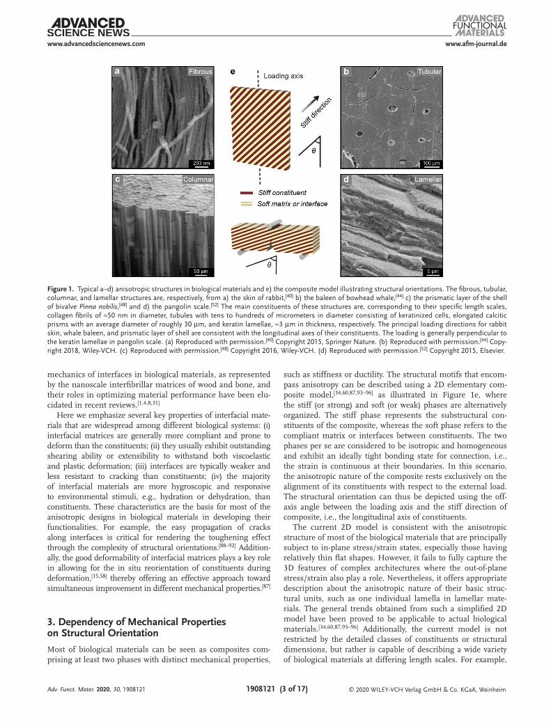
The resistance of a material to elastic deformation is repre-sented by its stiffness, which is characterized in terms of the elastic moduli, in particular the Young’s modulus. In the case of an orthotropic composite material, off-axis loading tends to result in shear deformation in addition to axial deformation. The relationship between the apparent Young’s modulus and structural orientation has been well established by considering the coupling of stress and strain between shear and normal deformation modes,[97–99] and has been specified for biological material systems.[34,93–95,100–104] As shown in Figure 2a, the Young’s modulus demonstrates a general decreasing trend with the increase of the off-axis angle. This has been experimentally
corroborated for different natural materials, with typical results for wood and bone presented in Figures 3 and 4.[100–121]
At the nano to micro length scales, the specific modulus, i.e., Young’s modulus normalized by density, along the axial direction of wood cells is negatively related to the microfibril angle (MFA), i.e., the inclination angle of cellulose micro-fibrils in the major part of wood cell wall, specifically the S2 layer in Figure 3a, relative to the longitudinal axis of wood cells, for differing species of wood.[15,104,115,117,118] This is also the case for bone strips containing bundles of nanoscale col-lagen fibrils for both dry and wet conditions (Figure 4b).[111,116] Similarly, the stiffness of wood and bone is governed by the off-axis angle of wood cells or bone osteons away from the loading direction at the mesoscale or tissue level (Figures 3b and 4c).[101,103,105–109,114] It is noted that the variation in Young’s modulus is not monotonic, but rather shows a slight increase toward the orthogonal orientation where the loading is perpen-dicular to the longitudinal axis of constituents,[87,97] as shown in the inset of Figure 2a. This is presumed to result from the constrained lateral deformation of the matrix by the stiff rein-forcement in such a configuration.
3.2. Strength
The strength, indicating the material’s resistance to inelastic deformation and damage, can be accessed for any uniaxial direction of an orthotropic composite according to the Tsai–Hill failure criterion.[97,122–124] This criterion, although developed based on the elastic behavior of a unidirectional composite layer, is also applicable to unidirectional composites comprising a number of layers that are isotropic along the transverse pro-file and are principally subject to in-plane stress. It cannot cap-ture the detailed failure modes and mechanisms of materials, but can well describe the variation in strength with orienta-tion regardless of how materials fail. This criterion has been
Adv. Funct. Mater. 2020, 30, 1908121
Figure 2. General varying trends in the mechanical properties of a) Young’s modulus, b) strength, and c) fracture toughness with structural orienta-tion in an orthotropic composite. The inset in (a) is a magnified view of the dashed box. The inset in (c) illustrates the deflection of a crack along the interface and its propagation across constituents. The fracture toughness is represented using the reciprocal of the effective stress intensity at the crack tip produced by applied load. The solid curve in (c) depicts the extrinsic toughening effect by crack deflection. The dashed curve in (c) indicates the fracture toughness generated from crack propagation across constituents in the range of high structural orientation where the applied load is nearly perpendicular to the longitudinal axis.

www.afm-journal.dewww.advancedsciencenews.com
1908121 (5 of 17) © 2020 WILEY-VCH Verlag GmbH & Co. KGaA, Weinheim
proved to be applicable to a variety of synthetic and biological materials.[122–128] As shown in Figure 2b, the tensile strength presents a general decreasing trend as the external load devi-ates away from the longitudinal axis of constituents. Similar orientation dependence exists in the case of compressive loading except that the smooth increase of strength becomes more evident in the large orientation range. The general varia-tions are essentially similar to those predicted by other strength theories, such as the Hoffman, Drucker–Prager, and ellipse failure criteria.[128–132]
Wood is a good example with its anisotropic strength dictated by the orientation of its wood cells, as shown by the Tsai–Hill criterion (Figure 3c).[101,117,118,133] Similar variations in strength have been observed in cortical bone at differing dimensions, i.e., with respect to collagen fibril bundles (Figure 4b) or com-prising bone lamellae and osteons (Figure 4c).[106,107,111,112,114,116] Even for trabecular bone that is characterized by a high porosity and 3D interconnection of trabeculae with thickness of tens to hundreds of micrometers, the strength is usually anisotropic and differs with loading direction relative to the principal tra-becular axis.[134–138] The bone volume fraction, i.e., the volume of trabeculae per unit volume of trabecular bone, has been rec-ognized as a key factor determining the properties of trabec-ular bone[134,137]; however, it cannot describe the mechanical anisotropy caused by the architectures in bone.[135–138] Instead, the bone volume fraction of trabecular bone along its principal axis projected onto the loading direction, which is negatively
associated with the off-axis angle, has been shown to have a close correlation with the compressive strength,[135] as shown in Figure 4d. Additionally, the failure of composites containing constituents with high aspect ratios is frequently caused by mechanical instability under compression along near longitu-dinal directions.[97] In this case, the strength may be enhanced by increasing the structural orientation, specifically to decrease the axial stress in order to inhibit buckling of the constituents.
3.3. Fracture Toughness
The toughness depicts the resistance of materials to fracture, specifically by resisting the extension of pre-existing cracks based on fracture mechanics. A material may derive its fracture resistance from two fundamental strategies termed intrinsic toughening and extrinsic toughening.[139,140] Intrinsic tough-ening represents the suppression of cracking through the dissipation of mechanical energy in resisting damage processes, e.g., ahead of a crack tip, which is primarily realized via the inherent plasticity of materials. In contrast, extrinsic tough-ening offers an alternative approach by shielding the crack tip from applied stress, thereby decreasing the driving force for crack extension; such shielding mechanisms operate at, or behind, the crack tip. The cracks in orthogonal composites are generally localized in the weak matrices or at the interfaces between constituents; this is generally the case for biological
Adv. Funct. Mater. 2020, 30, 1908121
Figure 3. Effects of structural orientation on the stiffness and strength of wood. a) Dependence of specific modulus, i.e., Young’s modulus normalized by tissue density, along the axial direction of wood cells on the microfibril angle (MFA) in wood cell walls for differing specifies.[15,104,115,117,118] Some of the data describe the post-yield stiffness of wood beyond their yield points and are denoted as E2/ρ.[15] The hydration state and moisture content (by weight) of wood samples are indicated in parenthesis. The inset illustrates the hierarchical structure of wood.[87] Variations in b) Young’s modulus and c) strength of different wood tissues containing large bundles of wood cells as a function of the off-axis angle of wood cells with respect to the loading axis.[101,103,105,117,118] The inset in (a): Reproduced with permission.[87] Copyright 2019, Elsevier.

www.afm-journal.dewww.advancedsciencenews.com
1908121 (6 of 17) © 2020 WILEY-VCH Verlag GmbH & Co. KGaA, Weinheim
systems.[68,96,140] The role of structural orientation can be to deflect the crack away from mode I plane (of maximum ten-sile stress), which is the most preferred cracking path with the maximum stress intensity in monolithic materials.[141,142] The toughening efficiency of this extrinsic mechanism can be pro-gressively enhanced at increasing degrees of crack deflection. Given a constant intrinsic damage resistance of the constituent phases, the fracture toughness of a composite is determined by the driving force for cracking generated by the applied load, a higher driving force leading to a lower toughness.
The fracture toughness, represented using the reciprocal of the effective stress intensity at the crack tip, demonstrates an increasing trend toward higher structural orientation owing to enhanced crack deflection,[34,87] as shown in Figure 2c. In addi-tion, cracks may tend to propagate across the constituents for loading directions that are nearly perpendicular to the longitu-dinal axis. This leads to diminished toughening by crack deflec-tion, as indicated by the dashed curve, yet may still dissipate large amounts of energy during the process, thereby generating other toughening mechanisms, such as the pull out of liga-ment bridges from the matrix. The fracture toughness of cor-tical bone, for example, is clearly dependent on its structural orientation.[14,53,68,143–150] As shown in Figure 5a, more energy is required for crack extension as the misalignment between bone lamellae and loading axis increases.[143,144] Specifically, the lon-gitudinal and transverse configurations with cracks parallel or perpendicular to the lamellae exhibit distinctly different fracture behavior and toughening mechanisms. The 0° (longitudinal)
orientation is characterized by straight, smooth cracking paths caused by the splitting of collagen fibers, lamellae, or interface failure along the osteonal boundaries, although bone in this orientation is still toughened by means of crack bridging by “uncracked ligaments” (Figure 5b). In comparison, the crack is significantly deflected and twisted for the 90° (transverse) ori-entation, which plays a more effective role in the toughening of bone (Figure 5c).[145–150]
4. Toughening by Complexity of Structural Orientations
The preferred propagation of cracks through a weak matrix or along a weak interface makes it possible to impede the evolution of damage by complicating the cracking paths via increasing the complexity of structural orientations. Such a toughening strategy is widely employed in biological materials, especially those that have evolved to withstand impact loads.[3,6,25,59] In particular, the structural orientations are constantly varied over 3D space in many cases, leading to distinctly complex paths for crack extension as compared to simple in-plane deflection or kinking. This is represented by the crossed-lamellar structure, which is encompassed in a variety of mollusk shells.[88–90,151–155] Such structure generally involves a hierarchical organization spanning at least two levels of dimensions. Taking the bivalve Strongylocentrotus purpuratus (S. purpuratus) shell for example, the lamellae with different alignments of lower-level aragonite
Adv. Funct. Mater. 2020, 30, 1908121
Figure 4. Dependences of stiffness and strength of bone on structural orientation. a) Schematic illustration of the hierarchical structure of bone. b,c) Variations in the Young’s modulus and strength of cortical bone at differing length scales: b) bone strips comprising bundles of mineralized collagen fibrils in dry and wet states,[111,116] and c) bone tissues consisting of bone lamellae and osteons.[103,106,107,112,114] d) Dependence of compres-sive strength on the bone volume fraction of principal axis projected onto the loading direction (BV/TV cos θ H1) in trabecular bone.[134,135] The inset in (d) shows the representative 3D structure of trabecular bone from bovine tibia.[134] The dashed line in (d) is a linear fit of data indicating the general varying trend. (b) Adapted with permission.[111] Copyright 2008, Wiley-VCH. The inset in (d): Reproduced with permission.[134] Copyright 2001, Annual Reviews.

www.afm-journal.dewww.advancedsciencenews.com
1908121 (7 of 17) © 2020 WILEY-VCH Verlag GmbH & Co. KGaA, Weinheim
platelets are alternatively assembled along torturous bounda-ries; the platelets within each lamella exhibit the same ori-entations,[151,152] as shown in Figure 6a. These lamellae often have irregular geometries and display mutual intersections among them. The large density of interfaces and the compe-tition between various fracture mechanisms, e.g., inter- and trans-cracking of constituents at differing length scales, lead to considerable spatial tortuosity for crack propagation, and as such make the crossed-lamellar structure markedly efficient in toughening a material.
The twisted plywood structure, termed the Bouligand struc-ture, is another excellent prototype of intricate orientations in nature.[54,56–58,70,102,110,156–164] It features a helicoidally stacking arrangement of unidirectional fiber layers in a periodic fashion and is found in a range of biological materials, including the exoskeletons of crustaceans and insects,[54,102,159,160,164] fish scales,[58,157] bone osteons (Figure 4),[70,110] and the dactyl clubs of mantis shrimps (Figure 6b).[56,57,158,161] Such a structure is particularly effective in resisting damage or impact along the orthogonal direction of layers. In the more brittle Bouligand structures, as seen in the exoskeletons of crustaceans, cracks are directed to twist continuously along the out-of-plane con-tours as they grow,[91,92] as shown in Figure 6b. This acts to increase the surface area for cracking and promote the nuclea-tion of multiple microcracks without significant coalescence between them. Specifically, crack twisting produces mixed-mode stress states at the crack front even under initially pure mode I loading condition. The effective mode I stress inten-sity at the crack tip and crack driving force represented by the strain energy release rate with crack extension can also be decreased,[91,92,162,163] as shown in Figure 6c. Additionally, the Bou-ligand structure is capable of dissipating mechanical energy by filtering the shear stress waves in the case of dynamic loading,[161] thereby endowing materials with enhanced impact resistance.
5. Robust and Releasable Adhesion by Anisotropic Contact
Geckos and many insects like cicadas and ladybirds have evolved special adhesive tissues to maneuver on random rough surfaces, e.g., vertical walls or ceilings.[78–81,165–170] The adhe-sion must be robust enough to allow for reliable attachment even in the case of unknown surface flaws, and simultaneously be easily releasable upon the movement of animals. Taking the geckos for example,[78–81] the adhesion force is generated from the van der Waals interaction between contact surface and hundreds of thousands of keratinous hairs, termed setae, on their toes, as shown in Figure 7a. These setae have a length of 30–130 µm and are arranged into a series of lamellae. Each seta is branched toward its tip in a hierarchical fashion into hundreds of fibrils, called spatulas, which have a width of 100–500 nm and possess pads at their ends. The attachment and detachment motions are accomplished, respectively, by rolling in (or griping) and rolling out (or peeling) the toes.[80,81,165] The hierarchically fibrillar structure of setae has been revealed to play a key role in ensuring its macroscopic adhesive robust-ness as the work of adhesion can be exponentially enhanced by increasing hierarchy.[81,165,170] Additionally, the differing charac-teristic dimensions for each hierarchy down to the nanometer level endows the setae with an excellent tolerance to flaws of varying length scales that exist at the rough surfaces.
The easy detachment and reversible switching between attachment and detachment are principally associated with the asymmetrical nature of the setae. The pulling experi-ment on a single seta from a substratum indicated an obvious dependence of detachment force on the pulling direction.[79] The strongest adhesion occurs at an inclination angle of around 30° with respect to the contacting surface. This is corroborated by finite element modeling simulations of the contact on a substrate by a single seta or an elastic tape. As
Adv. Funct. Mater. 2020, 30, 1908121
Figure 5. Effects of structural orientation on the fracture toughness of cortical bone. a) Variations in the energy required for crack extension as a func-tion of the principal orientation of mineralized collagen fibrils in cortical bone and typical cracking morphologies for the longitudinal (0°) and trans-verse (90°) orientations.[143,144] The inset illustrates the configurations of samples for the measurement of fracture toughness. b,c) Scanning electron microscopy and 3D synchrotron computed microtomography images showing the toughening mechanisms of cortical bone for cracking along the b) longitudinal and c) transverse orientations.[146,148] (a) Adapted with permission.[143] Copyright 2005, Springer Nature. (b) and (c) Reproduced with permission.[146] Copyright 2015, Wiley-VCH.

www.afm-journal.dewww.advancedsciencenews.com
1908121 (8 of 17) © 2020 WILEY-VCH Verlag GmbH & Co. KGaA, Weinheim
shown in Figure 7b, the failure of adhesion is dominated by the mode of sliding and detachment, respectively, for pulling angles smaller and larger than 30°.[81,165] The maximum and minimum values of adhesion strength are obtained when pulling at 30° and along the perpendicular direction of sur-face. Similar trend also exists for an anisotropic material in contact with a rough surface,[165] as shown in Figure 7c. The adhesive energy originates not only from the cohesive force at the interface, but also from the elasticity of the contact mate-rial. By considering the strain energy release rate of a system with an interfacial crack representing some random contact flaw, the adhesion strength can be seen to vary markedly with the pulling direction for a material having significantly higher stiffness along its longitudinal axis. This contrasts to the case of isotropic material where the adhesion is much less sensi-tive to pulling angle. The anisotropic nature of adhesion ena-bles feasible switching between a robust attachment and easy detachment by tuning the direction of pulling force, which can be readily achieved by exerting different muscles in the case of geckos.
6. Programmable Dynamic Response by Controlled Expansion
Upon absorbing or desorbing water, biological composites with a preferred alignment of constituents tend to swell or shrink anisotropically because of the more hygroscopic
nature of their interfacial matrices than their stiff constitu-ents.[4,8,77,82] The deformation is most pronounced over the orthogonal profile but is limited along the longitudinal orien-tation where the stiffness exhibits a maximum. This allows for the realization of programmable dynamic responses or actuations in biological tissues based on the regulation of their anisotropic architectures. Such mechanisms are particu-larly effective in plant systems even when they consist of dead cells.[77,82,171–181] For example, the upper region of the scale in pinecones comprises highly aligned micro/nanoscale cel-lulose fibers along the long axis (Figure 8a).[82,83,171] The con-siderable shrinkage of the lower sclereids region along the length direction, combined with a high dimensional stability of the upper region, leads to outward bending of scales upon dehydration to open the cone and release seeds. Similarly, the valves of chiral seedpods also feature a bilayer structure; nevertheless, the cellulose fibers are oriented at roughly ±45° with respect to the longitudinal axis in their outer and inner layers (Figure 8b).[172] The opening of the pod is activated by the twisting of valves induced by the asymmetrical shrinkage between the two layers. Differing from hydro-driven actua-tions, seed release can additionally be stimulated by heat, e.g., after exposure to fire, for plants in fire-prone ecosystems where the anisotropic structures also play a key role. The Banksia attenuata is a good example which demonstrates pre-ferred alignments of cellulose fibrils along the orthogonal and length directions of the follicle valves in its meso- and endo-carp layers (Figure 8c).[176] The longitudinal shrinkage of the
Adv. Funct. Mater. 2020, 30, 1908121
Figure 6. Toughening effects in biological materials with crossed-lamellar and Bouligand structures. a) Schematic illustration of the crossed-lamellar structure and complexity of cracking paths in bivalve S. purpuratus shell.[151,152] The differing orientations of aragonite platelets in adjacent lamellae are indicated by the white arrows. b) The Bouligand structure in the dactyl club of the mantis shrimp and illustrations of the crack twisting through the structure.[57,92] The twisted angle Φ is defined as the inclination of twisted straight crack front relative to its initial flat plane. c) Variations in the crack driving force in terms of the strain energy release rate with crack extension (solid curve) and the local stress intensities for mode I, II, and III stress-states, KI, KII, and KIII (dashed curves), normalized by those for initially pure mode I loading as a function of the twisted angle in the Bouligand structure.[92] (a) Adapted with permission.[152] Copyright 2015, Elsevier. (b) Reproduced with permission.[92] Copyright 2017, Elsevier.

www.afm-journal.dewww.advancedsciencenews.com
1908121 (9 of 17) © 2020 WILEY-VCH Verlag GmbH & Co. KGaA, Weinheim
mesocarp is thus restricted by the endocarp during the drying process of the follicle, creating considerable residual stresses in the valves. The stresses can be released by heating because of the decreased stiffness of the endocarp, which triggers the opening of the follicle.
The mechanistic fundamentals for such nonmetabolic dynamic responses of plant systems can be interpreted by approximating a plant cell as a thin-walled hollow cylinder comprising a series of concentric layers of constituents.[174,181] The stiff cellulose fibrils are embedded at a given MFA in the compliant matrix which is assumed to swell or shrink isotropi-cally with humidity. By excluding the torsional deformation of the cylinder, quantitative relationships have been established for the axial stress in the cell when its length is kept constant, the axial strain in the absence of any constraint, and the effec-tive Young’s modulus.[174] As shown in Figure 8d, the swelling of the matrix produces either tensile or compressive stresses in the cell along the longitudinal direction, which is dependent on the fibril orientation. Specifically, tensile stresses or axial contraction can be generated because of the geometrical con-straint by the fibrils, but only at MFAs smaller than 45°; the cell invariably expands in axial direction with a low stiffness for MFAs larger than 45°. This serves as the basis for com-plex actuations in plants, which are generally realized by combining specific regions with different local alignments of cellulose fibrils.
7. Enhanced Contact Damage Resistance by Varying Orientations
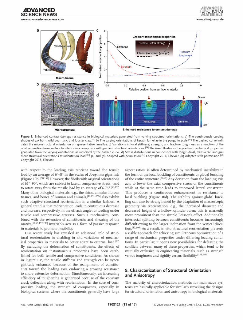
A wide range of biological materials are subject to contact loading in applications where the applied force is localized at their tips or surfaces. Typical examples of such macrotissues include the naturally evolved weapons that are primarily used for fighting or feeding, e.g., the tusks of walrus and wild boar, the horns of yak and beetle, lobster claw, spider fang, and worm jaw (Figure 9a).[33,34,164,182–186] These tissues necessitate an effective protection to themselves while maximizing the offence and damage exerted to opponents. A common feature is that they often exhibit curved shapes with their long axes gradually deviated away from external load from tip to base—the load is generally along the tangential direction at tip. Similar design protocols can also be found in the microstructures of many bio-logical materials, particularly those serving as protective armors like mollusk shells and pangolin scales (Figure 9b).[34,52,187,188] The constituents are gradually tilted at an increasing inclina-tion with respect to external load, e.g., caused by the biting of predators, with increasing depth from loading surfaces.
The continuous variation in structural orientations, at both macro and micro levels, produces an increase in the off-axis angle with the distance from the loading site, thereby offering a feasible approach for creating mechanical property gradients in materials. Figure 9c shows the variations in local mechanical
Adv. Funct. Mater. 2020, 30, 1908121
Figure 7. Orientation-dependent adhesion in gecko’s foot and an anisotropic composite with a surface. a) Hierarchical structure of gecko’s foot and its attachment and detachment from a glass ceiling.[81,170] ST, BR, and SP are short for, respectively, seta, branch, and spatula. b) Dependence of the pull-off force on the pulling orientation for a single seta of a gecko from a surface obtained by finite element modeling simulations.[81] c) Variations in the adhesion strength normalized by its minimum as a function of the pulling angle for an anisotropic composite, as compared to an isotropic material, in contact with a rough surface with crack-like flaw.[165] The inset illustrates the configuration for the pulling of an anisotropic composite with a contact orientation as 30°. Images of a gecko’s foot and toe in (a): Adapted with permission.[170] Copyright 2008, The Royal Society. Morphologies of the microstructure and the attachment and detachment of gecko’s foot from glass ceiling in (a): Reproduced with permission.[81] Copyright 2004, Elsevier. (b) and (c) Adapted with permission.[165] Copyright 2006, Elsevier.

www.afm-journal.dewww.advancedsciencenews.com
1908121 (10 of 17) © 2020 WILEY-VCH Verlag GmbH & Co. KGaA, Weinheim
properties for a composite where the constituents are parallel and perpendicular, respectively, to external load at the surface and in the interior, with a gradual transition in between.[34] There is a general trend of increasing stiffness and strength toward the surface, which creates an improved resistance to contact deformation and damage initiation. Meanwhile, the materials become more compliant and display an increasing ability for plastic deformation toward the interior, which acts to effectively redistribute stress and dissipate mechanical energy. Additionally, the crack can be continuously deflected away from the mode I plane as it extends inward along the struc-ture, which plays an increasing role in toughening the material. Computational simulations have revealed an enhanced resist-ance in materials to contact damage from such graded mechan-ical properties (Figure 9d).[34] The varying orientation functions to distribute the stress over a broader region and alleviate the stress concentrations near the surface from indentation loads, in a more effective manner than in orthogonal composites with either longitudinal or transverse orientations. The graded microstructures result in markedly diminished damage rep-resented by the lowest penetration depth at a minimal cost
of stiffness; indeed, the indentation stiffness approaches that of composite with vertically aligned constituents. The combi-nation of a hard surface with a tough base is reminiscent of many graded designs in engineering, e.g., by surface nitriding or milling of metals.[189,190] However, biological systems offer a new means based on structural orientations without manipu-lation of composition, residual stress, or other microstructural characteristics like dimensions.
8. Simultaneous Property Optimization by Adaptive Reorientation
The easy shear of the interfacial matrix in biological compos-ites allows for the in situ reorientation of constituents during deformation as an adaptation to the external load. Simultaneous synchrotron X-ray diffraction experiments have revealed a pro-gressive decrease in the microfibril angle by more than 10° with elongation in a wet foil of Picea abies [L.] Karst. wood,[15] as shown in Figure 10a. Analogously, the nanoscale miner-alized collagen fibrils that are originally oriented at 15°–30°
Adv. Funct. Mater. 2020, 30, 1908121
Figure 8. Programmable dynamic responses in plant systems based on structural orientations. a) Closing and opening of a pinecone cut equatorially along its longitudinal section in wet and dry states,[82] and illustration about the dominant orientations of cellulose microfibrils in the upper and lower regions of pinecone scale.[83,171] b) The opening of the chiral seedpod and the preferred alignments of cellulose microfibrils (indicated by dashed lines) in the inner and outer layers of the valve.[172] c) Microcomputed tomography image of the longitudinal section of Banksia attenuata follicle and X-ray scattering images of the exocarp (Ex), mesocarp (Me), and endocarp (En) layers in the follicle valve.[176] d) Variations in the axial stress at constant length, the axial strain in the absence of constraint, and the effective Young’s modulus generated by swelling as a function of the microfibril angle for a plant cell represented using a hollow cylinder without considering the torsional deformation.[174] Morphologies of the closing and opening of a pinecone in (a): Reproduced with permission.[82] Copyright 2009, The Royal Society. Illustration about the structural orientation in the pinecone in (a): Adapted with permission.[83] Copyright 2013, Springer Nature. (b) Adapted with permission.[172] Copyright 2011, American Association for the Advancement of Science. (c) Adapted with permission.[176] Copyright 2017, Wiley-VCH. (d) Adapted with permission.[174] Copyright 2008, The Royal Society of Chemistry.
www.afm-journal.dewww.advancedsciencenews.com
1908121 (11 of 17) © 2020 WILEY-VCH Verlag GmbH & Co. KGaA, Weinheim
with respect to the loading axis reorient toward the tensile load by an average of 6°–8° in the scales of Arapaima gigas fish (Figure 10b).[58,157] However, the fibrils with original orientations of 61°–90°, which are subject to lateral compressive stress, tend to rotate away from the tensile load by an average of 6.75°.[58,157] Many other biological materials, e.g., the skins, annulus fibrous tissues, and bones of human and animals,[40,191–195] also exhibit such adaptive structural reorientation in a similar fashion. A general trend is that reorientation leads to continuous decrease and increase, respectively, in the off-axis angle for loading under tensile and compressive stresses. Such a mechanism, com-bined with the extension of constituents and shearing of the matrix,[40,58,157,195] invariably acts as a form of passive response in materials to promote flexibility.
Our recent study has revealed an additional role of struc-tural reorientation in enabling in situ variations of mechan-ical properties in materials to better adapt to external load.[87] By excluding the deformation of constituents, the effects of reorientation on instantaneous properties have been estab-lished for both tensile and compressive conditions. As shown in Figure 10c, the tensile stiffness and strength can be syner-gistically enhanced because of the realignment of constitu-ents toward the loading axis, endowing a growing resistance to more extensive deformation. Simultaneously, an increasing efficiency of toughening is generated because of the constant crack deflection along with reorientation. In the case of com-pressive loading, the strength of composites, especially in biological systems where the constituents generally have large
aspect ratios, is often determined by mechanical instability in the form of the local buckling of constituents or global buckling of the entire structure.[87,97] Any deviation from the loading axis acts to lower the axial compressive stress of the constituents while at the same time leads to improved lateral constraint. This produces a continuous enhancement in resistance to local buckling (Figure 10d). The stability against global buck-ling can also be strengthened by the adaptation of macroscopic geometry via reorientation, e.g., the increased diameter and decreased height of a hollow cylinder form; this is markedly more prominent than the simple Poisson’s effect. Additionally, interfacial splitting between constituents becomes increasingly difficult owing to the larger inclination from the vertical direc-tion.[87,196] As a result, in situ structural reorientation presents a viable approach for achieving simultaneous optimization of a range of mechanical properties under differing loading condi-tions. In particular, it opens new possibilities for defeating the conflicts between many of these properties, which tend to be mutually exclusive in engineering materials, such as strength versus toughness and rigidity versus flexibility.[139,140]
9. Characterization of Structural Orientation and Anisotropy
The majority of characterization methods for man-made sys-tems are basically applicable for similarly unveiling the designs for structural orientation and anisotropy in biological materials.
Adv. Funct. Mater. 2020, 30, 1908121
Figure 9. Enhanced contact damage resistance in biological materials generated from varying structural orientations. a) The continuously curving shapes of yak horn, wild boar tusk, and lobster claw.[34] b) The varying orientations of keratin lamellae in the pangolin scale.[52] The dashed curve indi-cates the microstructural orientation of representative lamellae. c) Variations in local stiffness, strength, and fracture toughness as a function of the relative position from surface to interior in a composite with gradient structural orientations.[34] The inset illustrates the gradient mechanical properties generated from the varying orientations as indicated by the dashed curve. d) Stress distributions in composites with longitudinal, transverse, and gra-dient structural orientations at indentation load.[34] (a) and (d) Adapted with permission.[34] Copyright 2016, Elsevier. (b) Adapted with permission.[52] Copyright 2015, Elsevier.

www.afm-journal.dewww.advancedsciencenews.com
1908121 (12 of 17) © 2020 WILEY-VCH Verlag GmbH & Co. KGaA, Weinheim
Special attention should be paid to the detailed length scales of structural characteristics from which the properties of materials are derived. For example, the strength of cortical bone originates largely from its nanoscale structure; neverthe-less, the fracture toughness, specifically in terms of extrinsic toughening strategies, is developed principally at the micro to meso length scales.[18,68,95,146,150] With the decrease in char-acteristic dimensions, the anisotropic structure of biological materials can be explored using optical microscopy, X-ray computed microtomography, scanning electron microscopy (SEM), and transmission electron microscopy. In particular, X-ray computed microtomography demonstrates a good feasi-bility in biological systems, especially cellular materials such as trabecular bone, because X-rays can easily penetrate through biological tissues.[134,137,164,182,197,198] Such approach is also viable for discerning the interactions between structure and cracks in 3D space,[46,146,148] thereby illuminating the toughening mecha-nisms generated from anisotropic designs. Additionally, the anisotropy in crystalline orientation in biominerals, e.g., in nacre, can be detected using electron backscatter diffraction and polarization-dependent imaging contrast mapping tech-niques.[199–201] The identification of chemically related nano-structures of biological materials, e.g., tooth enamel, dentin, and bone, is further enabled by atom probe tomography.[202,203]
The real-time imaging and quantification of material behavior, specifically with respect to structural orientation, are of particular significance for understanding the salient design principles of architectures in property optimization. In situ SEM, especially when performed inside an environmental chamber, offers a feasible means for monitoring the crack extension during fracture toughness measurements. This has been increasingly employed in biological and bioinspired mate-rials, particularly for accessing their crack-resistance curves with crack propagation,[140,197,204–206] as many of them exhibit small dimensions that exclude the determination of crack length using an extensometer. In situ small/wide-angle X-ray scattering (SAXS/WAXS) techniques demonstrate less strict constraints than in situ SEM on the sample dimension, hydra-tion state, loading condition, and electrical conductivity. By capturing the information of characteristic structural features, these approaches are effective for recognizing the structural orientations and their changes in biological materials during deformation, and even quantifying the local strains of indi-vidual constituents.[15,40,58,146,157,176,195] For example, SAXS and WAXS can be used to detect, respectively, the staggered spacing between collagen molecules (≈67 nm) and the crystalline lat-tice spacing of minerals in mineralized collagen fibrils, and thereby have been widely utilized in probing bones,[146,195] fish
Adv. Funct. Mater. 2020, 30, 1908121
Figure 10. Adaptive structural reorientation and spontaneously enhanced mechanical properties in biological materials. a) Changes in the microfibril angle during tensile deformation and synchrotron X-ray diffraction images for a wet slice of Picea abies [L.] Karst. wood.[15] b) Rotation of mineralized collagen fibrils with differing original orientations as a function of the macroscopic tissue strain during a tensile test on the Arapaima gigas fish scale.[58] c) Variations in the Young’s modulus, strength, and fracture toughness of composite with strain caused by structural reorientation during tensile deformation.[87] d) Increased resistance to local buckling and to global buckling and improved splitting toughness of composite as a result of structural reorientation during compressive deformation.[87] The insets in (c) and (d) illustrate the reorientation of structure and the salient micromechanisms by, respectively, rotating toward and deviating away from the loading axis under tension and compression. (a) Adapted with permission.[15] Copyright 2003, Springer Nature. (b) Adapted with permission.[58] Copyright 2013, Springer Nature.
www.afm-journal.dewww.advancedsciencenews.com
1908121 (13 of 17) © 2020 WILEY-VCH Verlag GmbH & Co. KGaA, Weinheim
scales,[58,157] and skins.[40] However, the irradiation dose needs to be controlled for SAXS/WAXS measurement to minimize the damage of structure and properties of biological materials induced by X-ray exposure. The critical irradiation dose without causing major deterioration of mechanical integrity has been determined to be around 35 kGy for human cortical bone.[207,208]
10. Conclusions and Outlook
The anisotropic composite architectures of biological materials provide them with a broad space for tailoring structural orien-tations. This presents the potential of a variety of designs to bestow different functionalities. Such designs are remarkably viable as they do not require any compositional changes or for-mation of new phases, and are not restricted to specific struc-tural dimensions. The interfacial matrix plays a key role in this aspect and needs to be finely regulated for bioinspired designs. The matrix should be compliant and weak enough to guide the propagation of cracks for achieving toughening via complexity of cracking paths. Nevertheless, a more responsive matrix is required for generating self-shaping or actuation performance. The anisotropic nature of constituents offers additional feasi-bility for such structural designs. This is represented by the setae of geckos that develop controlled adhesion based on the contact angle of fibrous spatulas in the absence of interfaces.
There are numerous designs in nature that can be identified as being devised with structural orientation and anisotropy, with
even more to be understood from the perspective of mechanics and materials science. The exploration of the common prin-ciples among differing biological systems is a central task as many designs are similar, e.g., as in bone and wood. To this end, it is critical to capture the key design motifs by excluding confusing variables associated with detailed chemical composi-tions and structural dimensions. A case in point is how a suture interface that encompasses constantly varying orientations intersects with a crack and whether it plays any role in tough-ening a material.[32,94,209–211] The specification of fundamental mechanics in line with naturally occurring structures could hopefully lead to deeper insights into many of these designs. The creation of a database about the chemical and structural characteristics as well as the mechanical and functional prop-erties of biological materials should be helpful for extracting common design motifs. Multiscale finite element modeling simulations could also offer an effective tool for understanding the principles.[212–214] A major challenge exists as how the effects of structural orientations are combined with those from other characteristics, such as gradients and structural hierarchy, at multiple length scales. The time scales should also be consid-ered for dynamic responses and adaptations.
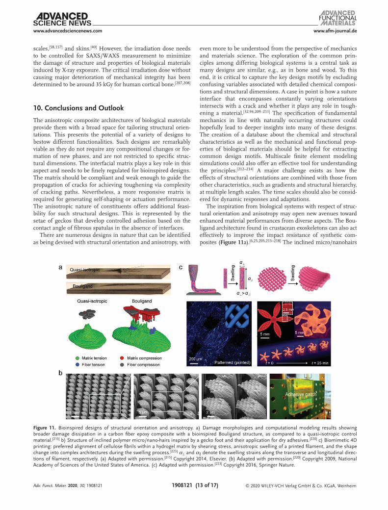
The inspiration from biological systems with respect of struc-tural orientation and anisotropy may open new avenues toward enhanced material performances from diverse aspects. The Bou-ligand architecture found in crustacean exoskeletons can also act effectively to improve the impact resistance of synthetic com-posites (Figure 11a).[6,25,205,215–218] The inclined micro/nanohairs
Adv. Funct. Mater. 2020, 30, 1908121
Figure 11. Bioinspired designs of structural orientation and anisotropy. a) Damage morphologies and computational modeling results showing broader damage dissipation in a carbon fiber epoxy composite with a bioinspired Bouligand structure, as compared to a quasi-isotropic control material.[215] b) Structure of inclined polymer micro/nano-hairs inspired by a gecko foot and their application for dry adhesives.[220] c) Biomimetic 4D printing: preferred alignment of cellulose fibrils within a hydrogel matrix by shearing stress, anisotropic swelling of a printed filament, and the shape change into complex architectures during the swelling process.[223] α⊥ and α∥ denote the swelling strains along the transverse and longitudinal direc-tions of filament, respectively. (a) Adapted with permission.[215] Copyright 2014, Elsevier. (b) Adapted with permission.[220] Copyright 2009, National Academy of Sciences of the United States of America. (c) Adapted with permission.[223] Copyright 2016, Springer Nature.

www.afm-journal.dewww.advancedsciencenews.com
1908121 (14 of 17) © 2020 WILEY-VCH Verlag GmbH & Co. KGaA, WeinheimAdv. Funct. Mater. 2020, 30, 1908121
resembling gecko’s setae endow robust attachment and easy detachment of a dry adhesive, which is promising for trans-port systems (Figure 11b).[78,219–222] The bioinspired 4D printing technique, replicating the anisotropic swelling/shrinkage of plant systems by aligning cellulose fibrils in a hydrogel matrix, demonstrates a particular feasibility in forming programmable architectures that are dynamically reconfigurable or self-shape-able (Figure 11c).[19,223–227] Similar dimensional effects can also be utilized to control the geometry of ceramics during the sin-tering process, thereby allowing for the manufacture of complex-shaped, high-temperature responsive elements.[228,229]
Successful bioinspiration relies essentially on the implemen-tation of the central design principles underlying structural ori-entations. That is why many biomimetic materials do not look like their natural prototypes, even from the perspective of their microstructures. The development of new processing techniques has enabled an increasingly effective manipulation of material architectures down to micro/nano length scales. However, it still remains a major challenge with regard to how to combine such advantages with the efficient mass production for tradi-tional processing methods. A basic strategy is to perform an ini-tial “bottom-up” assembly process before subsequent formation. However, this is inaccessible to the majority of current structural materials, especially metals and alloys, where the structuring and fabrication can hardly be separated. Additionally, it is particularly appealing if bioinspired structural orientations can be integrated with gradients, structural hierarchy, and other designs learned from nature. Their synergetic effects may offer a great potential toward unprecedented properties in man-made materials.
AcknowledgementsThe authors are grateful for the financial support by the National Natural Science Foundation of China under Grant Nos. 51871216 and 51331007 (for Z.Q.L. and Z.F.Z.), and from the Multi-University Research Initiative under Grant No. AFOSR-FA9550-15-1-0009 from the Air Force Office of Scientific Research to the University of California Riverside, specifically through a subcontract to the University of California Berkeley (for Z.Q.L. and R.O.R.).
Conflict of InterestThe authors declare no conflict of interest.
Keywordsanisotropy, bioinspiration, biological composites, biomechanics, structural orientations
Received: September 30, 2019Revised: November 20, 2019
Published online: January 3, 2020
[1] M. A. Meyers, J. McKittrick, P. Y. Chen, Science 2013, 339, 773.[2] S. Ling, D. L. Kaplan, M. J. Buehler, Nat. Rev. Mater. 2018, 3,
18016.[3] W. Yang, M. A. Meyers, R. O. Ritchie, Prog. Mater. Sci. 2019, 103, 425.
[4] M. Eder, S. Amini, P. Fratzl, Science 2018, 362, 543.[5] P. Fratzl, R. Weinkamer, Prog. Mater. Sci. 2007, 52, 1263.[6] A. R. Studart, Adv. Funct. Mater. 2013, 23, 4423.[7] Z. Q. Liu, M. A. Meyers, Z. F. Zhang, R. O. Ritchie, Prog. Mater.
Sci. 2017, 88, 467.[8] F. Barthelat, Z. Yin, M. J. Buehler, Nat. Rev. Mater. 2016, 1, 16007.[9] S. E. Naleway, M. M. Porter, J. McKittrick, M. A. Meyers, Adv.
Mater. 2015, 27, 5455.[10] U. G. K. Wegst, M. F. Ashby, Philos. Mag. 2003, 26, 2167.[11] S. Amini, A. Miserez, Acta Biomater. 2013, 9, 7895.[12] R. Weinkamer, P. Fratzl, Mater. Sci. Eng., C 2011, 31, 1164.[13] T. Speck, I. Burgert, Annu. Rev. Mater. Res. 2011, 41, 169.[14] S. Weiner, H. D. Wagner, Annu. Rev. Mater. Sci. 1998, 28, 271.[15] J. Keckes, I. Burgert, K. Fruhmann, M. Muller, K. Kolln,
M. Hamilton, M. Burghammer, S. V. Roth, S. Stanzl-Tschegg, P. Fratzl, Nat. Mater. 2003, 2, 810.
[16] I. Burgert, K. Fruhmann, J. Keckes, P. Fratzl, S. Stanzl-Tschegg, Trees 2004, 18, 480.
[17] H. D. Espinosa, J. E. Rim, F. Barthelat, M. J. Buehler, Prog. Mater. Sci. 2009, 54, 1059.
[18] U. G. K. Wegst, H. Bai, E. Saiz, A. P. Tomsia, R. O. Ritchie, Nat. Mater. 2015, 14, 23.
[19] J. A. Faber, A. F. Arrieta, A. R. Studart, Science 2018, 359, 1386.[20] C. Ortiz, M. C. Boyce, Science 2008, 319, 1053.[21] B. Su, Y. Tian, L. Jiang, J. Am. Chem. Soc. 2016, 138, 1727.[22] Z. Yin, F. Hannard, F. Barthelat, Science 2019, 364, 1260.[23] N. A. Yaraghi, D. Kisailus, Annu. Rev. Phys. Chem. 2018, 69, 23.[24] L. A. Berglund, I. Burgert, Adv. Mater. 2018, 30, 1704285.[25] S. M. Chen, H. L. Gao, Y. B. Zhu, H. B. Yao, L. B. Mao, Q. Y. Song,
J. Xia, Z. Pan, Z. He, H. A. Wu, S. H. Yu, Natl. Sci. Rev. 2018, 5, 703.
[26] G. X. Gu, M. Takaffoli, M. J. Buehler, Adv. Mater. 2017, 29, 1700060.
[27] P. Fratzl, J. R. Soc., Interface 2007, 4, 637.[28] M. Koyama, Z. Zhang, M. Wang, D. Ponge, D. Raabe, K. Tsuzaki,
H. Noguchi, C. C. Tasan, Science 2017, 355, 1055.[29] R. Lakes, Nature 1993, 361, 511.[30] J. Aizenberg, J. C. Weaver, M. S. Thanawala, V. C. Sundar,
D. E. Morse, P. Fratzl, Science 2005, 309, 275.[31] J. W. C. Dunlop, R. Weinkamer, P. Fratzl, Mater. Today 2011, 14, 70.[32] Y. Li, C. Ortiz, M. C. Boyce, J. Mech. Phys. Solids 2013, 61, 1144.[33] A. Miserez, T. Schneberk, C. Sun, F. W. Zok, J. H. Waite, Science
2008, 319, 1816.[34] Z. Q. Liu, Y. K. Zhu, D. Jiao, Z. Y. Weng, Z. F. Zhang, R. O. Ritchie,
Acta Biomater. 2016, 44, 31.[35] M. J. Harrington, A. Masic, N. Holten-Andersen, J. H. Waite,
P. Fratzl, Science 2010, 328, 216.[36] M. Xu, R. V. Lewis, Proc. Natl. Acad. Sci. USA 1990, 87, 7120.[37] B. Wang, W. Yang, J. McKittrick, M. A. Meyers, Prog. Mater. Sci.
2016, 76, 229.[38] Z. Q. Liu, D. Jiao, M. A. Meyers, Z. F. Zhang, Acta Biomater. 2015,
17, 137.[39] K. J. Coyne, X. X. Qin, J. H. Waite, Science 1997, 277, 1830.[40] W. Yang, V. R. Sherman, B. Gludovatz, E. Schaible, P. Stewart,
R. O. Ritchie, M. A. Meyers, Nat. Commun. 2015, 6, 6649.[41] W. Huang, A. Zaheri, J. Y. Jung, H. D. Espinosa, J. McKittrick,
Acta Biomater. 2017, 64, 1.[42] K. L. Johnson, M. W. Trim, D. K. Francis, W. R. Whittington,
J. A. Miller, C. E. Bennett, M. F. Horstemeyer, Acta Biomater. 2017, 48, 300.
[43] W. Huang, N. A. Yaraghi, W. Yang, A. Velazquez-Olivera, Z. Li, R. O. Ritchie, D. Kisailus, S. M. Stover, J. McKittrick, Acta Bio-mater. 2019, 90, 267.
[44] B. Wang, T. N. Sullivan, A. Pissarenko, A. Zaheri, H. D. Espinosa, M. A. Meyers, Adv. Mater. 2019, 31, 1804574.
www.afm-journal.dewww.advancedsciencenews.com
1908121 (15 of 17) © 2020 WILEY-VCH Verlag GmbH & Co. KGaA, WeinheimAdv. Funct. Mater. 2020, 30, 1908121
[45] A. Miserez, J. C. Weaver, P. B. Pedersen, T. Schneeberk, R. T. Hanlon, D. Kisailus, H. Birkedal, Adv. Mater. 2009, 21, 401.
[46] R. K. Nalla, J. H. Kinney, R. O. Ritchie, Biomaterials 2003, 24, 3955.[47] Z. Y. Weng, Z. Q. Liu, R. O. Ritchie, D. Jiao, D. S. Li, H. L. Wu,
L. H. Deng, Z. F. Zhang, J. Mech. Behav. Biomed. Mater. 2016, 64, 125.
[48] B. Bayerlein, L. Bertinetti, B. Bar-On, H. Blumtritt, P. Fratzl, I. Zlotnikov, Adv. Funct. Mater. 2016, 26, 3663.
[49] X. Li, W. C. Chang, Y. J. Chao, R. Wang, M. Chang, Nano Lett. 2004, 4, 613.
[50] A. Y. M. Lin, M. A. Meyers, K. S. Vecchio, Mater. Sci. Eng., C 2006, 26, 1380.
[51] D. Athanasiadou, W. Jiang, D. Goldbaum, A. Saleem, K. Basu, M. S. Pacella, C. F. Bohm, R. R. Chromik, M. T. Hincke, A. B. Rodriguez-Navarro, H. Vali, S. E. Wolf, J. J. Gray, K. H. Bui, M. D. McKee, Sci. Adv. 2018, 4, eaar3219.
[52] Z. Q. Liu, D. Jiao, Z. Y. Weng, Z. F. Zhang, J. Mech. Behav. Biomed. Mater. 2016, 56, 165.
[53] S. Weiner, W. Traub, H. D. Wagner, J. Struct. Biol. 1999, 126, 241.[54] P. Romano, H. Fabritius, D. Raabe, Acta Biomater. 2007, 3, 301.[55] L. Li, C. Ortiz, Nat. Mater. 2014, 13, 501.[56] N. A. Yaraghi, N. Guarin-Zapata, L. K. Grunenfelder, E. Hintsala,
S. Bhowmick, J. M. Hiller, M. Betts, E. L. Principe, J. Y. Jung, L. Sheppard, R. Wuhrer, J. McKittrick, P. D. Zavattieri, D. Kisailus, Adv. Mater. 2016, 28, 6835.
[57] J. C. Weaver, G. W. Milliron, A. Miserez, K. Evans-Lutterodt, S. Herrera, I. Gallana, W. J. Mershon, B. Swanson, P. Zavattieri, E. DiMasi, D. Kisailus, Science 2012, 336, 1275.
[58] E. A. Zimmermann, B. Gludovatz, E. Schaible, N. K. N. Dave, W. Yang, M. A. Meyers, R. O. Ritchie, Nat. Commun. 2013, 4, 2634.
[59] L. Li, C. Ortiz, Adv. Funct. Mater. 2015, 25, 3463.[60] I. Burgert, P. Fratzl, in The Expanding Cell, Vol. 6 (Eds: J. P. Verbelen,
K. Vissenberg), Springer, Berlin, Germany 2006, Ch. 9.[61] I. D. Cave, Wood Sci. Technol. 1968, 2, 268.[62] Y. Nishiyama, J. Wood Sci. 2009, 55, 241.[63] J. R. Barnett, V. A. Bonham, Biol. Rev. 2004, 79, 461.[64] A. N. Fernandes, L. H. Thomas, C. M. Altaner, P. Callow,
V. T. Forsyth, D. C. Apperley, C. J. Kennedy, M. C. Jarvis, Proc. Natl. Acad. Sci. USA 2011, 108, E1195.
[65] G. Tsoumis, Science and Technology of Wood: Structure, Properties, Utilization, Van Nostrand Reinhold, New York, NY, USA 1991.
[66] P. Fratzl, Curr. Opin. Colloid Interface Sci. 2003, 8, 32.[67] N. Reznikov, R. Shahar, S. Weiner, Acta Biomater. 2014, 10, 3815.[68] R. O. Ritchie, M. J. Buehler, P. Hansma, Phys. Today 2009, 62, 41.[69] J. Y. Rho, L. Kuhn-Spearing, P. Zioupos, Med. Eng. Phys. 1998,
20, 92.[70] W. Wagermaier, H. S. Gupta, A. Gourrier, M. Burghammer,
P. Roschger, P. Fratzl, Biointerphases 2006, 1, 1.[71] B. Yeom, T. Sain, N. Lacevic, D. Bukharina, S. H. Cha, A. M. Waas,
E. M. Arruda, N. A. Kotov, Nature 2017, 543, 95.[72] V. Imbeni, J. J. Kruzic, G. W. Marshall, S. J. Marshall, R. O. Ritchie,
Nat. Mater. 2005, 4, 229.[73] Z. Q. Liu, Z. Y. Weng, Z. F. Zhai, N. Huang, Z. J. Zhang, J. Tan,
C. B. Jiang, D. Jiao, G. Q. Tan, J. Zhang, X. Jiang, Z. F. Zhang, R. O. Ritchie, Acta Biomater. 2018, 81, 267.
[74] S. Bentov, P. Zaslansky, A. Al-Sawalmih, A. Masic, P. Fratzl, A. Sagi, A. Berman, B. Aichmayer, Nat. Commun. 2012, 3, 839.
[75] E. D. Yilmaz, G. A. Schneider, M. V. Swain, Philos. Trans. R. Soc., A 2015, 373, 20140130.
[76] M. Alberic, A. Gourrier, W. Wagermaier, P. Fratzl, I. Reiche, Acta Biomater. 2018, 72, 342.
[77] P. Fratzl, F. G. Barth, Nature 2009, 462, 442.[78] E. Arzt, Mater. Sci. Eng., C 2006, 26, 1245.[79] K. Autumn, Y. A. Liang, S. T. Hsieh, W. Zesch, W. P. Chan,
T. W. Kenny, R. Fearing, R. J. Full, Nature 2000, 405, 681.
[80] Y. Tian, N. Pesika, H. Zeng, K. Rosenberg, B. Zhao, P. McGuiggan, K. Autumn, J. Israelachvili, Proc. Natl. Acad. Sci. USA 2006, 103, 19320.
[81] H. Gao, X. Wang, H. Yao, S. Gorb, E. Arzt, Mech. Mater. 2005, 37, 275.
[82] I. Burgert, P. Fratzl, Philos. Trans. R. Soc., A 2009, 367, 1541.[83] R. M. Erb, J. S. Sander, R. Grisch, A. R. Studart, Nat. Commun.
2013, 4, 1712.[84] J. Bohlen, M. R. Nurnberg, J. W. Senn, D. Letzig, S. R. Agnew,
Acta Mater. 2007, 55, 2101.[85] D. Raabe, Acta Mater. 1997, 45, 1137.[86] J. Hirsch, T. Al-Samman, Acta Mater. 2013, 61, 818.[87] Z. Q. Liu, Y. Y. Zhang, M. Y. Zhang, G. Q. Tan, Y. K. Zhu,
Z. F. Zhang, R. O. Ritchie, Acta Biomater. 2019, 86, 96.[88] S. Kamat, X. Su, R. Ballarini, A. H. Heuer, Nature 2000, 405,
1036.[89] G. Mayer, Science 2005, 310, 1144.[90] J. D. Currey, A. J. Kohn, J. Mater. Sci. 1976, 11, 1615.[91] N. Suksangpanya, N. A. Yaraghi, R. B. Pipes, D. Kisailus,
P. Zavattieri, Int. J. Solids Struct. 2018, 150, 83.[92] N. Suksangpanya, N. A. Yaraghi, D. Kisailus, P. Zavattieri, J. Mech.
Behav. Biomed. Mater. 2017, 76, 38.[93] B. Ji, H. Gao, J. Mech. Phys. Solids 2004, 52, 1963.[94] P. Fratzl, O. Kolednik, F. D. Fischer, M. N. Dean, Chem. Soc. Rev.
2016, 45, 252.[95] H. Gao, Int. J. Fract. 2006, 138, 101.[96] J. W. Pro, F. Barthelat, MRS Bull. 2019, 44, 46.[97] R. M. Jones, Mechanics of Composite Materials, 2nd ed.,
Taylor-Francis, Philadelphia, PA, USA 1999.[98] H. T. Hahn, S. W. Tsai, J. Compos. Mater. 1973, 7, 102.[99] R. Hill, J. Mech. Phys. Solids 1963, 11, 357.
[100] H. D. Wagner, S. Weiner, J. Biomech. 1992, 25, 1311.[101] H. Yoshihara, Eur. J. Wood Wood Prod. 2009, 67, 183.[102] R. Yang, A. Zaheri, W. Gao, C. Hayashi, H. D. Espinosa, Adv. Funct.
Mater. 2017, 27, 1603993.[103] J. L. Katz, A. Meunier, J. Biomech. 1987, 20, 1063.[104] I. D. Cave, Wood Sci. Technol. 1969, 3, 40.[105] A. Reiterer, S. E. Stanzl-Tschegg, Mech. Mater. 2001, 33, 705.[106] D. T. Reilly, A. H. Burstein, J. Biomech. 1975, 8, 393.[107] M. H. Pope, J. O. Outwater, J. Biomech. 1974, 7, 61.[108] A. Reiterer, H. Lichtenegger, S. Tschegg, P. Fratzl, Philos. Mag. A
1999, 79, 2173.[109] J. Y. Rho, P. Zioupos, J. D. Currey, G. M. Pharr, J. Biomech. 2002,
35, 189.[110] H. S. Gupta, U. Stachewicz, W. Wagermaier, P. Roschger,
H. D. Wagner, P. Fratzl, J. Mater. Res. 2006, 21, 1913.[111] J. Seto, H. S. Gupta, P. Zaslansky, H. D. Wagner, P. Fratzl,
Adv. Funct. Mater. 2008, 18, 1905.[112] D. T. Reilly, A. H. Burstein, V. H. Frankel, J. Biomech. 1974, 7,
271.[113] J. D. Currey, K. Brear, P. Zioupos, J. Biomech. 1994, 27, 885.[114] D. Liu, H. D. Wagner, S. Weiner, J. Mater. Sci.: Mater. Med. 2000,
11, 49.[115] D. R. Cowdrey, R. D. Preston, Proc. R. Soc. London, Ser. B 1966,
166, 245.[116] V. Ziv, H. D. Wagner, S. Weiner, Bone 1996, 18, 417.[117] P. R. G. Hein, J. T. Lima, Maderas Ciencia Tecnol. 2012, 14, 267.[118] J. L. Katz, P. Spencer, Y. Wang, A. Misra, O. Marangos, L. Friis,
J. Mater. Sci. 2008, 43, 139.[119] F. G. Evans, R. Vincentelli, J. Biomech. 1969, 2, 63.[120] R. B. Martin, J. Ishida, J. Biomech. 1989, 22, 419.[121] Z. Fan, J. G. Swadener, J. Y. Rho, M. E. Roy, G. M. Pharr, J. Orthop.
Res. 2002, 20, 806.[122] V. D. Azzi, S. W. Tsai, Exp. Mech. 1965, 5, 283.[123] R. Hill, J. Mech. Phys. Solids 1965, 13, 189.

www.afm-journal.dewww.advancedsciencenews.com
1908121 (16 of 17) © 2020 WILEY-VCH Verlag GmbH & Co. KGaA, WeinheimAdv. Funct. Mater. 2020, 30, 1908121
[124] S. W. Tsai, in Fundamental Aspects of Fibre Reinforced Plastic Com-posites (Eds: R. T. Schwartz, H. S. Schwartz), Wiley Interscience, New York, NY, USA 1968.
[125] H. Cezayirlioglu, E. Bahniuk, D. T. Davy, K. G. Heiple, J. Biomech. 1985, 18, 61.
[126] C. Fuchs, D. Bhattacharyya, S. Fakirov, Compos. Sci. Technol. 2006, 66, 3161.
[127] S. C. Cowin, J. Appl. Mech. 1979, 46, 832.[128] D. Jiao, R. T. Qu, Z. Y. Weng, Z. Q. Liu, Z. F. Zhang, J. Biomech.
2019, 96, 109336.[129] Z. Hashin, J. Appl. Mech. 1980, 47, 329.[130] D. C. Drucker, W. Prager, Q. Appl. Math. 1952, 10, 157.[131] O. Hoffman, J. Compos. Mater. 1967, 1, 200.[132] R. T. Qu, Z. J. Zhang, P. Zhang, Z. Q. Liu, Z. F. Zhang, Sci. Rep.
2016, 6, 23359.[133] H. Yoshihara, M. Ohta, J. Wood Sci. 2000, 46, 159.[134] T. M. Keaveny, E. F. Morgan, G. L. Niebur, O. C. Yeh, Annu. Rev.
Biomed. Eng. 2001, 3, 307.[135] S. Tassani, C. Ohman, M. Baleani, F. Baruffaldi,
M. Viceconti, J. Biomech. 2010, 43, 1160.[136] X. S. Liu, P. Sajda, P. K. Saha, F. W. Wehrli, G. Bevill, T. M. Keaveny,
X. E. Guo, J. Bone Miner. Res. 2008, 23, 223.[137] R. Oftadeh, M. Perez-Viloria, J. C. Villa-Camacho, A. Vaziri,
A. Nazarian, J. Biomech. Eng. 2015, 137, 010802.[138] C. Ohman, M. Baleani, E. Perilli, E. Dall’Ara, S. Tassani,
F. Baruffaldi, M. Viceconti, J. Biomech. 2007, 40, 2426.[139] R. O. Ritchie, Nat. Mater. 2011, 10, 817.[140] M. E. Launey, R. O. Ritchie, Adv. Mater. 2009, 21, 2103.[141] B. Cotterell, J. R. Rice, Int. J. Fract. 1980, 16, 155.[142] M. Y. He, J. W. Hutchinson, Int. J. Solids Struct. 1989, 25, 1053.[143] H. Peterlik, P. Roschger, K. Klaushofer, P. Fratzl, Nat. Mater. 2006,
5, 52.[144] H. Peterlik, P. Roschger, K. Klaushofer, P. Fratzl, Int. J. Fract. 2006,
139, 395.[145] R. K. Nalla, J. S. Stölken, J. H. Kinney, R. O. Ritchie, J. Biomech.
2005, 38, 1517.[146] E. A. Zimmermann, R. O. Ritchie, Adv. Healthcare Mater. 2015, 4,
1287.[147] J. C. Behiri, W. Bonfield, J. Biomech. 1989, 22, 863.[148] E. A. Zimmermann, E. Schaible, H. Bale, H. D. Barth, S. Y. Tang,
P. Reichert, B. Busse, T. Alliston, J. W. Ager III, R. O. Ritchie, Proc. Natl. Acad. Sci. USA 2011, 108, 14416.
[149] R. K. Nalla, J. H. Kinney, R. O. Ritchie, Nat. Mater. 2003, 2, 164.[150] M. E. Launey, M. J. Buehler, R. O. Ritchie, Annu. Rev. Mater. Res.
2010, 40, 25.[151] D. Jiao, Z. Q. Liu, Z. J. Zhang, Z. F. Zhang, Sci. Rep. 2015, 5,
12418.[152] D. Jiao, Z. Q. Liu, R. T. Qu, Z. F. Zhang, Mater. Sci. Eng., C 2016,
59, 828.[153] X. W. Li, H. M. Ji, W. Yang, G. P. Zhang, D. L. Chen, J. Mech. Behav.
Biomed. Mater. 2017, 74, 54.[154] H. M. Ji, X. W. Li, D. L. Chen, Sci. Rep. 2017, 7, 40043.[155] W. Yang, G. P. Zhang, X. F. Zhu, X. W. Li, M. A. Meyers, J. Mech.
Behav. Biomed. Mater. 2011, 4, 1514.[156] Y. Bouligand, Tissue Cell 1972, 4, 189.[157] W. Yang, V. R. Sherman, B. Gludovatz, M. Mackey,
E. A. Zimmermann, E. H. Chang, E. Schaible, Z. Qin, M. J. Buehler, R. O. Ritchie, M. A. Meyers, Acta Biomater. 2014, 10, 3599.
[158] S. Amini, M. Tadayon, S. Idapalapati, A. Miserez, Nat. Mater. 2015, 14, 943.
[159] D. Raabe, C. Sachs, P. Romano, Acta Mater. 2005, 53, 4281.[160] V. Sharma, M. Crne, J. O. Park, M. Srinivasarao, Science 2009, 325,
449.[161] N. Guarin-Zapata, J. Gomez, N. Yaraghi, D. Kisailus, P. D. Zavattieri,
Acta Biomater. 2015, 23, 11.
[162] F. D. Fischer, O. Kolednik, J. Predan, H. Razi, P. Fratzl, Acta Biomater. 2017, 55, 349.
[163] Z. Song, Y. Ni, S. Cai, Acta Biomater. 2019, 91, 284.[164] J. Zhang, G. Q. Tan, M. Y. Zhang, D. Jiao, Y. K. Zhu, S. G. Wang,
Z. Q. Liu, D. X. Liu, Z. F. Zhang, J. Mech. Behav. Biomed. Mater. 2019, 91, 278.
[165] H. Yao, H. Gao, J. Mech. Phys. Solids 2006, 54, 1120.[166] K. Autumn, A. M. Peattie, Integr. Comp. Biol. 2002, 42, 1081.[167] H. Peisker, J. Michels, S. N. Gorb, Nat. Commun. 2013, 4, 1661.[168] K. Autumn, M. Sitti, Y. A. Liang, A. M. Peattie, W. R. Hansen,
S. Sponberg, T. W. Kenny, R. Fearing, J. N. Israelachvili, R. J. Full, Proc. Natl. Acad. Sci. USA 2002, 99, 12252.
[169] H. Gao, H. Yao, Proc. Natl. Acad. Sci. USA 2004, 101, 7851.[170] B. Chen, P. D. Wu, H. Gao, Proc. R. Soc. A 2008, 464, 1639.[171] C. Dawson, J. F. V. Vincent, A. M. Rocca, Nature 1997, 390, 668.[172] S. Armon, E. Efrati, R. Kupferman, E. Sharon, Science 2011, 333,
1726.[173] R. Elbaum, L. Zaltzman, I. Burgert, P. Fratzl, Science 2007, 316,
884.[174] P. Fratzl, R. Elbaum, I. Burgert, Faraday Discuss. 2008, 139, 275.[175] A. Rafsanjani, V. Brule, T. L. Western, D. Pasini, Sci. Rep. 2015, 5,
8064.[176] J. V. Huss, V. Schoeppler, D. J. Merritt, C. Best, E. Maire, J. Adrien,
O. Spaeker, N. Janssen, J. Gladisch, N. Gierlinger, B. P. Miller, P. Fratzl, M. Eder, Adv. Sci. 2018, 5, 1700572.
[177] H. Yamamoto, Wood Sci. Technol. 1999, 33, 311.[178] R. C. Neagu, E. K. Gamstedt, J. Mater. Sci. 2007, 42, 10254.[179] Y. Forterre, J. M. Skotheim, J. Dumais, L. Mahadevan, Nature
2005, 433, 421.[180] M. J. Harrington, K. Razghandi, F. Ditsch, L. Guiducci,
M. Rueggeberg, J. W. C. Dunlop, P. Fratzl, C. Neinhuis, I. Burgert, Nat. Commun. 2011, 2, 337.
[181] I. Burgert, M. Eder, N. Gierlinger, P. Fratzl, Planta 2007, 226, 981.[182] B. Bar-On, F. G. Barth, P. Fratzl, Y. Politi, Nat. Commun. 2014, 5,
3894.[183] M. G. Pontin, D. N. Moses, J. H. Waite, F. W. Zok, Proc. Natl.
Acad. Sci. USA 2007, 104, 13559.[184] Z. Q. Liu, Z. F. Zhang, R. O. Ritchie, Adv. Mater. 2018, 30, 1705220.[185] Z. L. Zhao, T. Shu, X. Q. Feng, Mater. Sci. Eng., C 2016, 58, 1112.[186] R. Das, R. N. Yadav, P. Sihota, P. Uniyal, N. Kumar, B. Bhushan,
Sci. Rep. 2018, 8, 14945.[187] W. Yang, I. H. Chen, B. Gludovatz, E. A. Zimmermann,
R. O. Ritchie, M. A. Meyers, Adv. Mater. 2013, 25, 31.[188] M. J. Chon, M. Daly, B. Wang, X. Xiao, A. Zaheri, M. A. Meyers,
H. D. Espinosa, J. Mech. Behav. Biomed. Mater. 2017, 76, 30.[189] K. Lu, Nat. Rev. Mater. 2016, 1, 16019.[190] Y. M. Lakhtin, Y. D. Kogan, Met. Sci. Heat Treat. 1978, 20, 667.[191] H. A. L. Guerin, D. M. Elliott, J. Biomech. 2006, 39, 1410.[192] J. A. Klein, D. W. L. Hukins, Biochim. Biophys. Acta, Gen. Subj.
1982, 719, 98.[193] P. F. Yang, X. T. Nie, D. D. Zhao, Z. Wang, L. Ren, H. Y. Xu,
J. Rittweger, P. Shang, J. Mech. Behav. Biomed. Mater. 2018, 79, 115.
[194] A. K. Dastjerdi, F. Barthelat, J. Mech. Behav. Biomed. Mater. 2015, 52, 95.
[195] C. Acevedo, M. Sylvia, E. Schaible, J. L. Graham, K. L. Stanhope, L. N. Metz, B. Gludovatz, A. V. Schwartz, R. O. Ritchie, T. N. Alliston, P. J. Havel, A. J. Fields, J. Bone Miner. Res. 2018, 33, 1066.
[196] C. G. Sammis, M. F. Ashby, Acta Metall. 1986, 34, 511.[197] R. O. Ritchie, MRS Bull. 2014, 39, 880.[198] L. Zhang, S. Wang, Materials 2018, 11, 1795.[199] R. A. Metzler, M. Abrecht, R. M. Olabisi, D. Ariosa, C. J. Johnson,
B. H. Frazer, S. N. Coppersmith, P. U. P. A. Gilbert, Phys. Rev. Lett. 2007, 98, 268102.
www.afm-journal.dewww.advancedsciencenews.com
1908121 (17 of 17) © 2020 WILEY-VCH Verlag GmbH & Co. KGaA, WeinheimAdv. Funct. Mater. 2020, 30, 1908121
[200] R. A. Metzler, D. Zhou, M. Abrecht, J. W. Chiou, J. Guo, D. Ariosa, S. N. Coppersmith, P. U. P. A. Gilbert, Phys. Rev. B 2008, 77, 064110.
[201] A. G. Checa, H. Mutvei, A. J. Osuna-Mascaro, J. T. Bonarski, M. Faryna, K. Berent, C. M. Pina, M. Rousseau, E. Macias-Sanchez, J. Struct. Biol. 2013, 183, 368.
[202] L. M. Gordon, M. J. Cohen, K. W. MacRenaris, J. D. Pasteris, T. Seda, D. Joester, Science 2015, 347, 746.
[203] A. L. Fontaine, A. Zavgorodniy, H. Liu, R. Zheng, M. Swain, J. Cairney, Sci. Adv. 2016, 2, e1601145.
[204] E. Munch, M. E. Launey, D. H. Alsem, E. Saiz, A. P. Tomsia, R. O. Ritchie, Science 2008, 322, 1516.
[205] M. Y. Zhang, D. Jiao, G. Q. Tan, J. Zhang, S. G. Wang, J. Y. Wang, Z. Q. Liu, Z. F. Zhang, R. O. Ritchie, ACS Appl. Nano Mater. 2019, 2, 1111.
[206] G. Q. Tan, J. Zhang, L. Zheng, D. Jiao, Z. Q. Liu, Z. F. Zhang, R. O. Ritchie, Adv. Mater. 2019, 31, 1904603.
[207] H. D. Barth, M. E. Launey, A. A. MacDowell, J. W. Ager III, R. O. Ritchie, Bone 2010, 46, 1475.
[208] H. D. Barth, E. A. Zimmermann, E. Schaible, S. Y. Tang, T. Alliston, R. O. Ritchie, Biomaterials 2011, 32, 8892.
[209] Y. Li, C. Ortiz, M. C. Boyce, Phys. Rev. E 2011, 84, 062904.[210] Y. Li, C. Ortiz, M. C. Boyce, Phys. Rev. E 2012, 85, 031901.[211] Z. Q. Liu, Z. F. Zhang, R. O. Ritchie, Acta Biomater. 2019, 102, 75.[212] W. Huang, D. Restrepo, J. Y. Jung, F. Y. Su, Z. Q. Liu, R. O. Ritchie,
J. McKittrick, P. Zavattieri, D. Kisailus, Adv. Mater. 2019, 31, 1901561.[213] S. Nikolov, M. Petrov, L. Lymperakis, M. Friak, C. Sachs,
H. O. Fabritius, D. Raabe, J. Neugebauer, Adv. Mater. 2010, 22, 519.
[214] S. Schmauder, I. Schafer, Mater. Today 2016, 19, 130.[215] L. K. Grunenfelder, N. Suksangpanya, C. Salinas, G. Milliron,
N. Yaraghi, S. Herrera, K. Evans-Lutterodt, S. R. Nutt, P. Zavattieri, D. Kisailus, Acta Biomater. 2014, 10, 3997.
[216] D. Ginzburg, F. Pinto, O. Iervolino, M. Meo. Compos. Struct. 2017, 161, 187.
[217] S. Gantenbein, K. Msania, W. Woigk, J. P. W. Sesseg, T. A. Tervoort, A. R. Studart, Nature 2018, 561, 226.
[218] Z. Jia, L. Wang, Acta Mater. 2019, 173, 61.[219] H. Lee, B. P. Lee, P. B. Messersmith, Nature 2007, 448, 338.[220] H. E. Jeong, J. K. Lee, H. N. Kim, S. H. Moon, K. Y. Suh, Proc. Natl.
Acad. Sci. USA 2009, 106, 5639.[221] M. T. Northen, C. Greiner, E. Arzt, K. L. Turner, Adv. Mater. 2008,
20, 3905.[222] L. F. Boesel, C. Greiner, E. Arzt, A. Del Campo, Adv. Mater. 2010,
22, 2125.[223] A. S. Gladman, E. A. Matsumoto, R. G. Nuzzo, L. Mahadevan,
J. A. Lewis, Nat. Mater. 2016, 15, 413.[224] S. Tibbits, Archit. Des. 2014, 84, 116.[225] A. R. Studart, Chem. Soc. Rev. 2016, 45, 359.[226] Q. Ge, C. K. Dunn, H. J. Qi, M. L. Dunn, Smart Mater. Struct. 2014,
23, 094007.[227] A. Velasco-Hogan, J. Xu, M. A. Meyers, Adv. Mater. 2018, 30,
1800940.[228] F. L. Bargardi, H. Le Ferrand, R. Libanori, A. R. Studart,
Nat. Commun. 2016, 7, 13912.[229] G. Liu, Y. Zhao, G. Wu, J. Lu, Sci. Adv. 2018, 4, eaat0641.