structural engineering design calculations · wall design calculation sheet 3.1 lusaka residential...
TRANSCRIPT

Structural Engineering Design Calculations
Lusaka Residential Perimeter Walls F488a33J off Mutende Road Lusaka – Zambia
Brian C Chutu Bsc (Hons) Civil Engineering (UK), REng, MEIZ, MConsEZ Checked By:
Prepared for:
Bricch Consultants Limited

Subject Drg. Ref
Sheet No.
Project Job No. Made by Rev
Date Checked by
1. DESIGN STATEMENT
Introduction
Design Proposal
a)
b)
Design Codes
a) - BS 8110: Structural use of concrete
b) - BS 5628: Code of practice for use of masonry
1.1
1.2
Foundation
12.02.2018
LUSAKA RESIDENTIAL PERIMETER WALLS
F488a33J OFF MUTENDE ROAD KABULONGAC
It is required to provide detailed structural engineering design for a perimeter wall on plot
no. F488a33J off Mutende Road, Kabulonga, Lusaka Zambia property belonging to
Embassy of The United States of America.
Client proposed a solid masonry wall reinforced with steel bars for additional strength.
The wall height to be not less than 2.8m high according to Client's standards.
A free standing wall shall be considered and designed to resist wind pressure and gravity
load from its self weight.
The wall shall be founded on traditional reinforced concrete strip footing.
The foundation shall be designed using soil investigation parameters provided in the
Geotechnical Report.
CALCULATION SHEET 1.1
1720 BCC
GENERAL LOADING
Structural Masonry
Wall
The wall shall be constructed using 7N Concrete Hollow Blocks filled with Grade 10
(10Mpa) mass concrete. The wall strength shall be enhanced by inserting vertical
reinforcing bars through block cells. Horizontal reinforcing bars shall be provided in every
mortar joint and tied to vertical bars. The horizontal bars shall thus act as distribution
bars to vertical main bars.
1.3
The following Standard Codes of Practice shall be employed for the design of structural
elements:
Structural Concrete

Subject Drg. Ref
Sheet No.
Project Job No. Made by Rev
Date Checked by
DESIGN DATA
Characteristic Dead Load
Concrete Density =
200mm thick Solid Concrete Blockwork =
Characteristic Imposed Load
Wind Load (to Client's Standard) =
Soil Properties (obtained from Geotechnical Investigation Report)
Ground Allowable Bearing Capacity =
Angle of Internal Friction ( Ø) =
Soil Density (assumed) =
35 °
18 kN/m ³
24 kN/m ³
100 kN/m²
2.1
C
1.20
4.31
BCC
kN/m²
kN/m²
CALCULATION SHEET
1720
12.02.2018
DESIGN DATA
LUSAKA RESIDENTIAL PERIMETER WALLS
F488a33J OFF MUTENDE ROAD KABULONGA

Subject Drg. Ref
Sheet No.
Project Job No. Made by Rev
Date Checked by
CASE 1: WIND PRESSURE OUTSIDE OF PROPERTY
CHECK WALL STABILITY
Sliding
Consider wind pressure acting on 1m wall length
= kN
= kN
Consider gravity loads acting on 1m wall length
= kN
= kN
= kN
= kN
= kN
12.02.2018 C
3.60
WALL DESIGN
CALCULATION SHEET 3.1
1720 BCCLUSAKA RESIDENTIAL PERIMETER WALLS
F488a33J OFF MUTENDE ROAD KABULONGA
3.60
16.38
10.08
11.52
2.88
40.86
𝑊𝑖𝑛𝑑 𝑝𝑟𝑒𝑠𝑠𝑢𝑟𝑒, 𝑊𝑘 = 1.2 x 3
𝑊𝑒𝑖𝑔ℎ𝑡 𝑜𝑓 𝑊𝑎𝑙𝑙,𝑊𝑤 = 3.8 x 4.31
𝑊𝑒𝑖𝑔ℎ𝑡 𝑜𝑓 𝐵𝑎𝑠𝑒,𝑊𝑏 = 1.4 x 0.3 x 24
𝑊𝑒𝑖𝑔ℎ𝑡 𝑜𝑓 𝑆𝑜𝑖𝑙 1,𝑊𝑠1 = 0.8 x 0.8 x 18
𝑊𝑒𝑖𝑔ℎ𝑡 𝑜𝑓 𝑆𝑜𝑖𝑙 2,𝑊𝑠2 = 0.8 x 0.2 x 18
𝑻𝒐𝒕𝒂𝒍 𝑮𝒓𝒂𝒗𝒊𝒕𝒚 𝑳𝒐𝒂𝒅,𝑾𝒕
𝑻𝒐𝒕𝒂𝒍 𝑾𝒊𝒏𝒅 𝑳𝒐𝒂𝒅,𝑾𝒌

Subject Drg. Ref
Sheet No.
Project Job No. Made by Rev
Date Checked by
= 0.4 x 40.86 = kN
=
x
> OK
Overturning
Take moments about Point P1
∑ of overturning moment,
= x
= x = kNm
∑ of restoring moment,
x =
x =
x =
x =
kNm
Factor of Safety against Overturning,
> OK
Wall is satisfactory
against sliding
16.38 0.90 14.74
10.08 0.70 7.06
11.52 0.40 4.61
C
CALCULATION SHEET 3.2
1720 BCC
WALL DESIGN
LUSAKA RESIDENTIAL PERIMETER WALLS
F488a33J OFF MUTENDE ROAD KABULONGA
1.20 3.00
9.36
16.34
12.02.2018
= 4.54
2.6
3.6 2.6 9.36
1.50
16.34
2.88 1.10 3.17
29.57
29.57=
2.00
= 3.16
Wall is satisfactory
against overturning
𝑇𝑎𝑘𝑖𝑛𝑔 𝐹𝑟𝑖𝑐𝑡𝑖𝑜𝑛, 𝐹𝑓 = 𝜇𝑊𝑡
𝐴𝑠𝑠𝑢𝑚𝑒 𝑝𝑎𝑠𝑠𝑖𝑣𝑒 𝑝𝑟𝑒𝑠𝑠𝑢𝑟𝑒 𝑓𝑜𝑟𝑐𝑒, 𝐹𝑝 = 0
Therefore factor of safety against sliding = 𝐹𝑓
𝑊𝑘
𝑀𝑜𝑣𝑒𝑟
𝑊𝑘
𝑀𝑟𝑒𝑠𝑡

Subject Drg. Ref
Sheet No.
Project Job No. Made by Rev
Date Checked by
GROUND BEARING PRESSURE
Consider Moment about centreline of base
M = x =
x =
x =
x =
kNm
N = =
M
N
Therefore, maximum ground pressure occurs at toe, which is given by:
=
=
<
Ground pressure at the heel:
CALCULATION SHEET 3.3
1720 BCC
WALL DESIGN
LUSAKA RESIDENTIAL PERIMETER WALLS
F488a33J OFF MUTENDE ROAD KABULONGA
7.60
40.86
7.60
1.44
<6
=1.4
0.23=
3.60 2.05
2.30
40.86
11.52 0.20
2.88 0.50
=
-3.53-10.08 0.35
= 0.186
D
6
Ground Bearing Pressure
OK
Allowable
(200kN/m ²)
1.96
45.58
1.4
40.86=+
D ²D
6MN+
7.38
m
12.02.2018 C
N 6M
D D ²
40.86 45.58
-
52.44 kN/m ²
=
=
= 5.93 kN/m ²1.4 1.96
-
𝑊𝑡
𝑃𝑡𝑜𝑒
𝑃ℎ𝑒𝑒𝑙

Subject Drg. Ref
Sheet No.
Project Job No. Made by Rev
Date Checked by
REINFORCEMENT
Wall
Stem Height = m
Horrizontal pressure on stem due to wind:
= x = kNm
Design Moment at Wall Base:
x x
Effective Depth
Assume Bar Ø = mm
Thus d = - - 6 = mm
= x x
x x = kNm
Steel Area
x
x x
Z = [ - / )]
= mm
x 10 ⁶
x x
LUSAKA RESIDENTIAL PERIMETER WALLS
F488a33J OFF MUTENDE ROAD KABULONGA
3.80
1.20 3.00 3.60
M =
12.02.2018 C
CALCULATION SHEET 3.4
1720 BCC
WALL DESIGN
= 8.64 kNm
12
=1.60 3.60 3.00
2
94
0.156 15 10 ᶟ
94 ² 10 ⁻⁶ 20.68
200 100
0.9
= 0.140=7 10 ᶟ 94 ²
8.64 10 ⁶
76
0.87 500 75.94
8.64= 262
94 0.50 0.25 0.140
A =Y10@200mm c/c
(393mm ²) is adequatemm ²/m
𝐹𝑤𝑖𝑛𝑑
𝛾𝑡𝐹𝑤𝑖𝑛𝑑ℎ𝑠2
𝑀𝑢
𝑆𝑖𝑛𝑐𝑒 𝑀𝑢 > 𝑀, 𝑐𝑜𝑚𝑝𝑟𝑒𝑠𝑠𝑖𝑜𝑛 𝑟𝑒𝑖𝑛𝑓𝑜𝑟𝑐𝑒𝑚𝑒𝑛𝑡 𝑖𝑠 𝑛𝑜𝑡 𝑟𝑒𝑞𝑢𝑖𝑟𝑒𝑑
𝐾 =𝑀
𝑓𝑐𝑢𝑏𝑑²
+ √(

Subject Drg. Ref
Sheet No.
Project Job No. Made by Rev
Date Checked by
REINFORCEMENT Cont'd
Provide nominal reinforcement for horizontal or distribution bars
0.13%bh = x x = mm ²/m
Base
Toe
Soil Pressure:
= x = kN/m ²
= x = kN/m ²
( - )
= kN/m ²
Loading:
= x = kN/m ²
= x = kN/m ²
LUSAKA RESIDENTIAL PERIMETER WALLS
F488a33J OFF MUTENDE ROAD KABULONGA
WALL DESIGN
C
0.13% 10 ᶟ 200 260 Y10@200mm c/c
(393mm ²) is adequate
CALCULATION SHEET 3.5
1720 BCC
1.4 52.44 73.41
1.4 5.93 8.304
0.90 73.41
12.02.2018
= 8.3 +8.30
1.4
50.16
11.52 1.4 16.13
2.88 1.4 4.032
𝑃1
𝑃2
𝑃3
𝑊1
𝑊2

Subject Drg. Ref
Sheet No.
Project Job No. Made by Rev
Date Checked by
REINFORCEMENT Cont'd
Design Moment @ Point P2
x x x x
x x x
2 x 3
= kN/m ²
Steel Area
x 10 ⁶
x x
LUSAKA RESIDENTIAL PERIMETER WALLS
F488a33J OFF MUTENDE ROAD KABULONGA
WALL DESIGN
CALCULATION SHEET 3.6
1720 BCC
12.02.2018 C
1.4016.13 0.90 0.90
-16.3
10.08 0.4
42+=M
-50.16 0.9 ²
2-
65.11 0.90 0.90
Y10@200mm c/c
(393mm ²) bottom is
adequate0.87 500 89.30A =
16.31= 420 mm ²/m
Subject Drg. Ref
Sheet No.
Project Job No. Made by Rev
Date Checked by
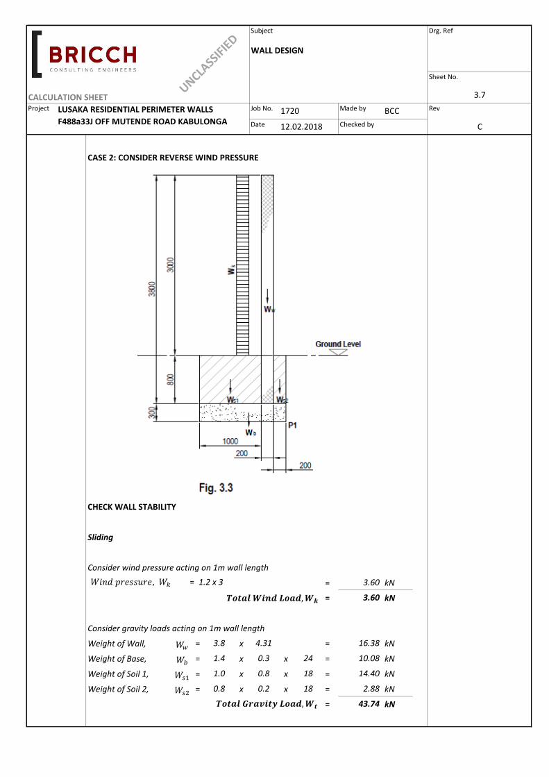
CASE 2: CONSIDER REVERSE WIND PRESSURE
CHECK WALL STABILITY
Sliding
Consider wind pressure acting on 1m wall length
= kN
= kN
Consider gravity loads acting on 1m wall length
Weight of Wall, = x = kN
Weight of Base, = x x = kN
Weight of Soil 1, = x x = kN
Weight of Soil 2, = x x = kN
= kN
LUSAKA RESIDENTIAL PERIMETER WALLS
F488a33J OFF MUTENDE ROAD KABULONGA
3.8 4.31
1.4 0.3 10.0824
1.0 0.8 18
2.88
43.74
0.8 0.2 18
1720 BCC
12.02.2018 C
3.60
3.60
16.38
14.40
WALL DESIGN
CALCULATION SHEET 3.7
𝑊𝑖𝑛𝑑 𝑝𝑟𝑒𝑠𝑠𝑢𝑟𝑒, 𝑊𝑘 = 1.2 x 3
𝑊𝑤
𝑻𝒐𝒕𝒂𝒍 𝑮𝒓𝒂𝒗𝒊𝒕𝒚 𝑳𝒐𝒂𝒅,𝑾𝒕
𝑻𝒐𝒕𝒂𝒍 𝑾𝒊𝒏𝒅 𝑳𝒐𝒂𝒅,𝑾𝒌
𝑊𝑏
𝑊𝑠1
𝑊𝑠2

Subject Drg. Ref
Sheet No.
Project Job No. Made by Rev
Date Checked by
Stability of wall against sliding similar to CASE 1, therefore check not required
Overturning
Take moments about Point P1
∑ of overturning moment,
= x
= x = kNm
∑ of restoring moment,
x =
x =
x =
x =
kNm
Factor of Safety against Overturning,
> OK
GROUND BEARING PRESSURE
Consider Moment about centreline of base
M = x =
x =
x =
x =
kNm
LUSAKA RESIDENTIAL PERIMETER WALLS
F488a33J OFF MUTENDE ROAD KABULONGA
2.88 0.50 1.44
12.83
22.77
=22.77
=
3.60 2.60 9.36
16.38 0.30 4.91
-14.40 0.20 -2.88
2.439.36
2.00 Wall is satisfactory
against overturning
10.08 0.60 6.05
14.40 0.80 11.52
2.88 0.10 0.29
2.6
3.6 2.6 9.36
16.38 0.30 4.91
CALCULATION SHEET 3.8
1720 BCC
12.02.2018 C
WALL DESIGN
𝑀𝑜𝑣𝑒𝑟
𝑊𝑘
𝑀𝑟𝑒𝑠𝑡

Subject Drg. Ref
Sheet No.
Project Job No. Made by Rev
Date Checked by
GROUND BEARING PRESSURE Cont'd
N = = kN
M
N
Therefore, maximum ground pressure occurs at toe, which is given by:
=
=
<
Ground pressure at the heel:
REINFORCEMENT
LUSAKA RESIDENTIAL PERIMETER WALLS
F488a33J OFF MUTENDE ROAD KABULONGA
Moments in CASE 2 would be similar but in reverse of CASE 1, therefore provide nominal
reinforcement Y10@200mm c/c in Top, main and distribution bars
=43.74
-77
= -8.04 kN/m ²1.4 1.96
70.53 kN/m ²1.4 1.96
Allowable
(100kN/m ²)
Ground Bearing Pressure
OK
=N
-6M
D D ²
N+
6M
D D ²
43.74+
77=
>D
6
=1.4
= 0.2 m6
43.74
=12.83
= 0.343.74
1720 BCC
12.02.2018 C
WALL DESIGN
CALCULATION SHEET 3.9
𝑊𝑡
𝑃𝑡𝑜𝑒
𝑃ℎ𝑒𝑒𝑙