structural engineering cw - 4th year
TRANSCRIPT

University of the West of Scotland Civil Engineering
Design Criteria & Information – page 1 of 12
STRUCTURAL ENGINEERING 3 DESIGN COURSEWORK 2014-2015 A REINFORCED CONCRETE BUILDING STRUCTURE DESIGN CRITERIA AND INFORMATION Introduction A Client has commissioned the design and construction of a small building, with a structural frame of the overall shape and dimensions shown below. Within the Design Team, you are the Consultant for both the structural engineering (structural frame and foundations) and the external civil engineering (external works, e.g. roads and drainage). But, in this Coursework, you will only be responsible for the design of the structural frame of this building. The Design Team also includes: an Architect, a Mechanical & Electrical (M&E) Engineer, and a Quantity Surveyor. As part of the Client’s commission, you will be producing a final Structural Design Report, which will incorporate the four Phases of this Coursework. Requirements of the Client’s Design Brief x Main Structural Dimensions: The general plan and cross-section of the building structure are as shown below. The overall plan dimensions A and B (in metres), are between the centres of the columns. The building has two storeys, and the height dimensions between floor levels are given in terms of H. You will be assigned a unique combination of dimensions A, B, & H. Dimensions A, B, & H are presented in the tables on pages 8 & 9 of this set of sheets. In practice, there would also be stairs and a lift (including for disability access), but these are not considered in this Coursework.
H + 0.5 m
B m
A m
Plan on the Building Structure
e.g. Level 1
1
1
Section 1– 1
Height dimensions are to tops of slabs and beams, and also to top-of-foundation level.
Top of found
H m
R
Level
1
G Grd Floor Slab
A/2 m A/2 m
B/2 m
B/2 m

University of the West of Scotland Civil Engineering
Design Criteria & Information – page 2 of 12
Requirements of the Client’s Design Brief continued The above structural floor plan layout was chosen as one to be designed and built, after giving consideration to the following three main design factors. x Building Function: The Client will lease the new building to an organization which will use it as a testing workshop, of a general industrial type. x Building Material: The frame is to be of reinforced concrete, which is to be highly durable. x Flexibility for Future Use: In the future, the Client wants to be able to lease the building to a different organisation, which is likely to use the building for a different purpose. The Client has asked the Design team to design the structural layout so as to optimise its potential for this future change of usage. The Client considers the criterion of “Flexibility for Future Use” to be the dominant design factor. Consider the three gridlines parallel to the A-dimension direction. A possible alternative plan layout has 4 columns, with 3 beam spans, along each of these three ‘A-direction’ gridlines. But that would have limited the alternative, future, potential uses of the internal space of this building. Design Coursework Phases 1 to 4 There will be a series of four Phases of the Structural Design Coursework for this Building: x Phase 1: Preliminary cross-section sizing of the main structural elements of the building. x Phase 2: The Principal Structural Frame: design loadings, computer analyses, and critical evaluation of the computer output information. x Phase 3: Computer assisted justification of the design of a Principal Continuous Beam. x Phase 4: The overall conclusions and production of the final drawings. In each of the 9.00-10.00am classes in Weeks 1, 2, 4, & 6, a lecturer will give an introduction to the respective Phases 1, 2, 3, &4. You will submit one Final Design Report in Week 9 (Mon 17th Oct). You have been issued with this first set of Design Criteria & Information pages 1 to 12. This set is currently available on the Structural Engineering 3 module on the UWS virtual learning environment Moodle. For each of the Coursework Phases 1, 2, 3, & 4, there is an additional set of complementary design criteria & information sheets. The complementary set for Phase 1 is currently on Moodle. The corresponding complementary set for each of Phases 2, 3, & 4 will become available on Moodle from 10.00am on the Tuesday of the preceding week, i.e. in Weeks 1, 3, & 5. All of these sources of design criteria & information will enable you to carry out the specified design and analysis exercises. x In Phase 1: For the specified plan layout of columns and beam spans – on page 1 above, you will do the following. First, you will estimate approximate cross-sectional dimensions for each of the typical reinforced concrete elements, which are: a Slab, a Principal Beam, and a Column. Second, you will also make approximate estimates of the steel reinforcement in the cross-section of only the continuous Principal Beam, at two critical locations along its span lengths. x In Phase 2: You will consider the corresponding Principal Structural Frame (in a vertical plane), which includes the above Principal Beam. You will calculate two combinations of design loading on the Frame. You will use a structural analysis computer programme to assist you in the calculation of critical bending moments, shear forces and deflection information, for the whole Principal Frame, and particularly for only the continuous Principal Beam at Level 1 of the Frame. x In Phase 3: For only the continuous Principal Beam at Level 1, you will use a structural design computer programme to assist you in checking and justifying your Phase 1 estimates of the Beam cross-sectional dimensions, and of the Beam reinforcement. x In Phase 4: You will produce drawings of your final design and details of the reinforced concrete structure of the building. You will make overall, evaluative conclusions, which will include a review and critical assessment of the whole integrated design process involved in Phases 1 to 4.
University of the West of Scotland Civil Engineering
Design Criteria & Information – page 3 of 12
The Elements of the Building Structure: General Information The main elements of this building structure are of reinforced concrete. Some of the main types of structural element are considered below. There is a set of illustrative ‘General Arrangement and Detail Drawings’ on pages 10 and 11 of this set of pages. These drawings are included as illustrative examples for your guidance. Reinforced concrete construction is monolithic in that all joints (or connections) between beams, slabs, and columns, are rigid (or continuous), as illustrated by the drawings. These drawings should help you to visualise these elements and how they are inter-connected. x Columns: The building has two storeys. All columns are to have a square cross-section, with
the same dimensions, from Foundation to Roof Level. Columns that are located on the external perimeter, or edges, are called ‘external columns’, and all others are called ‘internal columns’. On the plan drawing on page 1 of this set of pages, in each of the two main right-angled directions on plan, grid lines are drawn through the centres of all columns.
x Beams: At each of Level 1 and Roof Level (R), beams span between columns, in each of
the two main right-angled directions on plan. The centre-lines of beams lie along the grid-lines through the centres of the
columns. The span length of each beam is measured between the centres of its supporting columns. All beam dimensions (of length and of cross-section) are to be the same at both Level 1 and Roof Level. Beams around the external perimeter, or edges, are called ‘external beams’, and all others are called ‘internal beams’.
A ‘Principal Internal Beam’ is an internal beam onto which the floor slabs span. So, the span direction of a ‘Principal Internal Beam’ is at right-angles to the span direction of the floor slabs that it supports (you should also refer to the following section on Floor Slabs). The ‘Principal Internal Beam’ will be a continuous beam of three beam-elements or spans. In all of the Coursework Phases 1 to 4, it is important that you identify which beam is the ‘Principal Internal Beam’.
x Floor Slabs: At each of both Level 1 and Roof Level (R), all floor slabs span between beams.
Slabs are to be assumed to span only ‘one-way’, along the direction with the shorter distance between the centre-lines of their supporting beams, and at right-angles to these beams. Slab span lengths are measured between the centres of these beams.
In practice, for slab spans of 5 metres or longer, a ribbed slab normally may be a more economical option than a flat, or solid, slab. However, in this building structure, all floor slabs are to be ‘flat’, rather than ‘ribbed’. This is because some of the industrial testing processes involve concentrated loads being applied to different locations on the top surface of floor slabs, and the thinner topping slab thicknesses (e.g. 100 mm) of a ribbed slab would have inadequate punching shear resistance. The thickness of all slabs is to be the same at both Level 1 and Roof Level (R).

University of the West of Scotland Civil Engineering
Design Criteria & Information – page 4 of 12
The Elements of the Building Structure: General Information continued x Structural Frame:
x Column Foundations: At the bottom of each column, there is to be an isolated base, or pad foundation, or found. Each found is of reinforced concrete. The top of each found is to be 500mm below the top of a 200mm thick ground bearing floor slab at Ground Floor Level (G). ‘Internal’ founds, under ‘internal’ columns, are 2.5m x 2.5m x 0.25m. ‘External’ founds, under ‘external’ columns, are 1.5m x 1.5m x 0.25m. For the purposes of only the computer analyses of Phase 2, the support joint at the bottom of each column, which is at top-of-found level, is to be assumed to act as a pinned-support-joint, i.e. as a ‘pin’ (instead of being rigid, or fixed). Estimating the Cross-Sectional Dimensions of the main Structural Elements x Introduction: In the following sections, the method of making approximate estimates of element
cross-sectional dimensions is based on information from a book entitled “The Way We Build Now”, by Andrew Orton.
x Slabs: x Typical range of span lengths L …………………………….…… within the range of 5.0m to 6.6m x Range of recommended values of the ‘Span-to-Depth’ ratio L/h …….…………... 22 to 30
Overall Depth h (i.e. not the ‘effective-depth’ d of the slab): x For a simply supported slab: to get h for a given L, use a lower-range value of L/h. For a continuous slab: to get h for a given L, use a mid-range value of L/h. x Round-up the calculated value of h to the nearest 10mm.
A structural frame consists of a rigid, or continuous, framed assembly of two beams and the connected ‘external’ and ‘internal’ columns. A frame located at the external perimeter, or edge of the building, is called an ‘external frame’; and all other frames are called ‘internal frames’. A ‘Principal Internal Frame’ contains the ‘Principal Internal Beams’, which are defined on the previous page 3.
Top of found
R
Level
1
G Grd Floor Slab
h
h is the overall depth (in mm) L is the span length into the paper (in m or mm)
Part-Cross-Section of a typical Slab Element (e.g. approx. 1 m breadth, or width, of slab shown)
University of the West of Scotland Civil Engineering
Design Criteria & Information – page 5 of 12
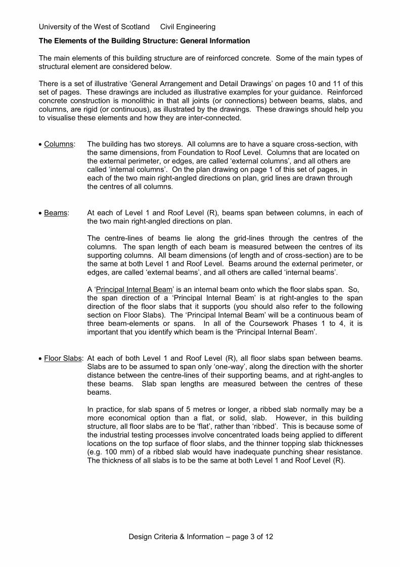
Dimensions of Structural Elements continued x A Principal Internal Beam: x Typical range of span lengths L ………………………………... Within the range of 8.5m to 10.0m x Range of recommended values of the ‘Span-to-Depth’ ratio L/h ……………….. 15 to 23
Overall Depth h (i.e. not the ‘effective-depth’ d of the beam): x For a simply supported beam: to get h for a given L, use a lower-range value of L/h. For a shorter-spanning continuous beam: use a mid-range value of L/h. For a longer-spanning continuous beam: use a lower-range value of L/h. x If the overall depth h is calculated as being less than 300mm, use h = 300mm. x Round-up the calculated value of h to the nearest 25mm. x For ‘external beams’, take dimension h to be the same as that of ‘internal beams’.
Breadth (or Width) b: x For ‘internal beams’, take b as the greater of either 500 mm or the column breadth (depth = breadth). x For ‘external beams’, take dimension b to be the same as that of the ‘internal beams’.
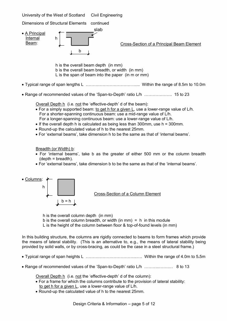
x Columns: In this building structure, the columns are rigidly connected to beams to form frames which provide the means of lateral stability. (This is an alternative to, e.g., the means of lateral stability being provided by solid walls, or by cross-bracing, as could be the case in a steel structural frame.) x Typical range of span heights L ……………….……………...…. Within the range of 4.0m to 5.5m x Range of recommended values of the ‘Span-to-Depth’ ratio L/h ………..…….… 8 to 13
Overall Depth h (i.e. not the ‘effective-depth’ d of the column): x For a frame for which the columns contribute to the provision of lateral stability: to get h for a given L, use a lower-range value of L/h.
x Round-up the calculated value of h to the nearest 25mm.
h
b = h
h is the overall column depth (in mm) b is the overall column breadth, or width (in mm) = h in this module L is the height of the column between floor & top-of-found levels (in mm)
Cross-Section of a Column Element
slab
h
b
h is the overall beam depth (in mm) b is the overall beam breadth, or width (in mm) L is the span of beam into the paper (in m or mm)
Cross-Section of a Principal Beam Element

University of the West of Scotland Civil Engineering
Design Criteria & Information – page 6 of 12
Submission of the final Structural Design Report You will be required to submit only one final Structural Design Report, which will include your component reports and drawings for all of the Coursework Phases 1 to 4. This Report is to be submitted within one A4-sized file, or folder. It is to be submitted into the box in Room D161, before 4.00pm on Monday 17th November’14, which is in Week 9. (Refer to the Module Information Sheets, Section 5.3, for the required format and procedure of making this submission.) Marking Schedule for the Structural Design Report Phase 1 Section Marks 1.1(a) to (c) 11 1.2(a) to (c) 13 1.3(a) & (b) 6 Phase 2 Section 2.1(a) & (b) 30 2.2(a) & (b) 15 Phase 3 Section 3.1(a) to (c) 30
3.2 10 Phase 4 Section 4.1(a)(i) to (iii) 25 4.1(b)(i) & (ii) 20
4.2 15 Overall Presentation (of Phases 1 to 4) 45 Total for all of Phases 1 to 4 220 marks For this Coursework component of this module, the final total mark will be a percentage mark, in proportion to the above mark out of 220.

University of the West of Scotland Civil Engineering
Design Criteria & Information – page 7 of 12
Your Approach to the Design Coursework Introduction In this Fourth Year Structural Design Coursework, your approach to carrying out these design and analysis activities will be of a more open-ended nature, and will require a greater degree of personal interpretation, than was required in Third Year. In this Coursework, you are to work more independently, and with less supervision or help from the Lecturers, than was the case in Third Year. The Lecturers will be able to help you only to clarify the interpretation of a point of information, or to help redirect you if you are completely stuck at some point. The Lecturers will only carry out assessment of your submitted final Structural Design Report. Features of the final Structural Design Report The following are some expected general features of your Structural Design Report: x Report writing which is comprehensive and also coherent in its reporting, discussion and justification of the content being presented. x Text, and calculations, that are clear and straightforward to read and to understand. So as to clarify and justify the main points in your Report, as and where you consider it appropriate, your reporting should include the following features:
- At each stage, and in both written text and calculations, clearly explain what you are doing, and give adequate reasons or justifications.
- State any assumptions made, and the reasons for these, if appropriate. - Include references to any source documents or design standards. - Make relevant cross-references within your Report. - Add commentary text or notes to clarify or amplify the points you are presenting. Add
annotations and titles to drawings for this same purpose. The Client’s Criteria for the Form and Length of the Structural Design Report The following are criteria which should be followed in your production of your Design Report. x The Report should be of A4 size. Drawings can be A4 or A3, but any A3 drawings should be folded to A4 size in the Report (and still be easily accessed and read). x Excluding sections of text and drawings that are printed out from the two specified computer software programmes (i.e. GSA & the Concrete Centre TCC11 Spreadsheet), your own produced text and calculation pages should conform to the following criteria: - Do not use less than a 12 point font size. - A minimum outer edge margin of 2.54 cm should be used on all four edges of each page. - In the Paragraph Section on the top Home Ribbon of Word, do not use less than 1.5 lines spacing – and leave the Before and After settings as 0. x The Client requires that the final Structural Design Report should not be too long or too short. Your Report should have a target length that lies between 30 and 60 A4 sides-of-pages, and this includes text and drawings generated by the above two computer software programmes. You can add only two further additional paper cover sheets – one at the front, and one at the back. x If any of the above criteria are not adhered to in the Report, a proportional penalty will be applied by making a reduction in the overall Presentation mark for your Report.
University of the West of Scotland Civil Engineering
Design Criteria & Information – page 8 of 12
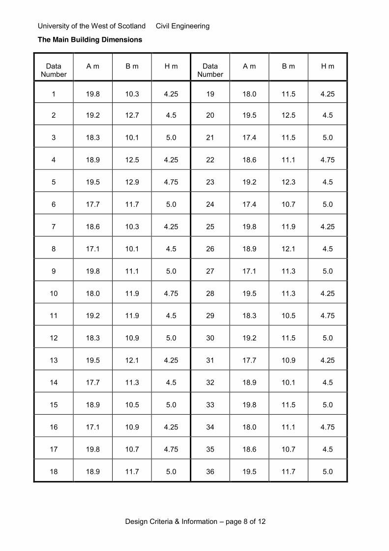
The Main Building Dimensions
Data
Number
A m
B m
H m
Data
Number
A m
B m
H m
1
19.8
10.3
4.25
19
18.0
11.5
4.25
2
19.2
12.7
4.5
20
19.5
12.5
4.5
3
18.3
10.1
5.0
21
17.4
11.5
5.0
4
18.9
12.5
4.25
22
18.6
11.1
4.75
5
19.5
12.9
4.75
23
19.2
12.3
4.5
6
17.7
11.7
5.0
24
17.4
10.7
5.0
7
18.6
10.3
4.25
25
19.8
11.9
4.25
8
17.1
10.1
4.5
26
18.9
12.1
4.5
9
19.8
11.1
5.0
27
17.1
11.3
5.0
10
18.0
11.9
4.75
28
19.5
11.3
4.25
11
19.2
11.9
4.5
29
18.3
10.5
4.75
12
18.3
10.9
5.0
30
19.2
11.5
5.0
13
19.5
12.1
4.25
31
17.7
10.9
4.25
14
17.7
11.3
4.5
32
18.9
10.1
4.5
15
18.9
10.5
5.0
33
19.8
11.5
5.0
16
17.1
10.9
4.25
34
18.0
11.1
4.75
17
19.8
10.7
4.75
35
18.6
10.7
4.5
18
18.9
11.7
5.0
36
19.5
11.7
5.0

University of the West of Scotland Civil Engineering
Design Criteria & Information – page 9 of 12
The Main Building Dimensions continued
Data
Number
A m
B m
H m
Data
Number
A m
B m
H m
37
18.3
11.3
4.25
55
19.2
10.7
4.25
38
17.4
10.3
4.5
56
18.6
12.3
4.5
39
19.2
11.1
5.0
57
19.8
13.1
5.0
40
17.7
10.5
4.25
58
18.0
10.3
4.75
41
19.8
12.7
4.75
59
18.9
10.9
4.5
42
17.1
10.5
5.0
60
19.5
10.1
5.0
43
18.3
11.7
4.25
61
18.6
11.9
5
44
19.2
10.3
4.5
62
18.9
12.5
5
45
17.4
11.1
5.0
63
19.5
11.7
4.25
46
19.5
10.5
4.75
64
17.4
11.5
4.25
47
18.6
11.5
4.5
65
19.8
11.5
4.25
48
17.7
10.1
5.0
66
18.3
11.7
5
49
19.8
12.3
4.25
67
19.5
12.1
5
50
18.9
11.3
4.5
68
18
11.5
5
51
18.0
10.7
5.0
69
19.8
11.1
4.25
52
18.6
11.9
4.25
70
17.7
11.7
4.25
53
19.5
10.9
4.75
71
19.2
11.1
4.25
54
18.3
12.1
5.0
72
17.1
10.9
4.5

University of the West of Scotland Civil Engineering
Design Criteria & Information – page 10 of 12
Reinforced Concrete Buildings: Typical General Arrangement and Detail Drawings The following are illustrative examples.
Plan on a Typical Floor Slab
indicates direction of typical slab span X
X 1 2 3 4 5
D
A
B
C
column grid-lines
(dimensions to be added)
Floor Slab Section X-X
(grid-numbers or letters, and dimensions to be added)
Cross-Section of Flat Slab
(dimension to be added)

University of the West of Scotland Civil Engineering
Design Criteria & Information – page 11 of 12
Reinforced Concrete Buildings: Typical General Arrangement and Detail Drawings cont’d The following are illustrative examples.
Cross-Section of Edge Beam Cross-Section of Main Beam
(dimensions to be added)
Cross-Section of Column
(dimensions to be added) (dimensions to be added)
University of the West of Scotland Civil Engineering
Design Criteria & Information – page 12 of 12
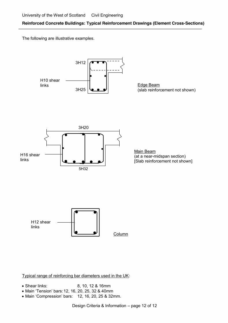
Reinforced Concrete Buildings: Typical Reinforcement Drawings (Element Cross-Sections) The following are illustrative examples. Typical range of reinforcing bar diameters used in the UK: x Shear links: 8, 10, 12 & 16mm x Main ‘Tension’ bars: 12, 16, 20, 25, 32 & 40mm x Main ‘Compression’ bars: 12, 16, 20, 25 & 32mm.
H16 shear links
Edge Beam (slab reinforcement not shown)
3H12
3H25
H10 shear links
Column
H12 shear links
Main Beam (at a near-midspan section) [Slab reinforcement not shown]
3H20
5H32

University of the West of Scotland
CIVIL ENGINEERING
Structural Engineering 3
COURSEWORK
Structural Design Report
Submission Date: 17/11/2014 Data No: 42 For the attention of Dr Ian McKenzie.

Course Work Structural Engineering 3
B00259789 Contents
CONTENTS 1.! Conceptual-Design:-Alternative-Structure-Layouts- 2!1.1! A$Column$and$Floor$Structure$Plan$Layout$ 2!a.! Drawings! 2!b.! Design!choices! 2!i.! Main!design!factor!adopted! 2!ii.! Alternative!floor!plan!layout! 2!
1.2! Drawings$of$the$Structural$Element$Cross?Sections$with$Estimated$Dimensions$ 2!a.! Slab! 2!b.! A!“Principal!Internal!Beam”! 3!c.! A!Column! 5!
1.3! Drawings$of$Estimated$Reinforcement:$Cross?Sections$of$the$Principal$Internal$Beam$ 6!a.! At,!or!near,!the!midFspan!of!the!beamFelement:! 6!i.! Outline!shape!of!the!beam’s!crossFsection! 6!ii.! Expected!steel!reinforcement!arrangement! 6!
b.! At!the!end!of!the!span!of!the!beamFelement:! 6!i.! Outline!shape!of!the!beam’s!crossFsection! 6!ii.! Expected!steel!reinforcement!arrangement! 7!
c.! Major!differences!between!the!reinforcement!information! 7!2.! The-Principal-Internal-Frame:-Design-Loadings- 8!2.1! Calculations$of$Characteristic$Loadings$and$Design$Loading$Combinations$ 8!a.! Principal!Internal!Frame! 8!iii.! Level!1!permanent!load!Gk1! 8!iv.! Roof!permanent!load!GkR! 9!v.! Level!1!variable!imposed!floor!load!Qk1! 9!vi.! Roof!variable!imposed!load!QkR! 9!vii.! Wind!loads!Wk! 9!
b.! Two!Design!Loading!Combinations:!Calculation!and!Drawings! 11!viii.! 1.35Gk!+!1.5Qk! 11!ix.! 1.35Gk!+!1.5Qk!+!0.75Wk! 11!
2.2! Computer?Assisted$Analyses$and$Evaluation$of$Critical$Analysis$Information$ 12!a.! Principal!Internal!Frame:!Input!Data!and!Output!Data! 12!i.! Input!Data! 12!x.! Output!Data! 16!
b.! Principal!Internal!Beam:!Critical!Output!Data! 20!3.! ComputerCAssisted-Justification- 24!3.1! Computer?Assisted$Justification$of$the$Estimated$Design$of$the$Principal$Internal$Beam$ 24!a.! Design!the!beam!to!be!adequate!in!resisting!the!selected!critical!bending!moments! 24!b.! Design!the!beam!to!be!adequate!in!resisting!the!selected!critical!shear!forces! 25!c.! Design!the!beam!to!be!adequate!in!regard!with!the!criterion!of!“deflection”! 26!
3.2! Presentation$and$Evaluation$of$the$Design$Computer$Output$Information$ 27!a.! Design!the!beam!to!be!adequate!in!resisting!the!selected!critical!bending!moments! 27!i.! No!wind!loading!at!support! 27!ii.! No!wind!loading!at!midFspan! 29!iii.! With!wind!loading!at!support! 31!iv.! With!wind!loading!at!midFspan! 33!
b.! Design!the!beam!to!be!adequate!in!resisting!the!selected!critical!shear!forces! 36!i.! At!support! 36!ii.! At!midFspan! 37!
c.! Design!the!beam!to!be!adequate!regarding!the!criterion!of!“deflection”! 38!i.! No!wind,!at!midFspan! 38!ii.! With!wind,!at!midFspan! 38!

Course Work Structural Engineering 3
B00259789
1
4.! Production-of-the-Final-Drawings-and-Conclusions- 39!4.1! Final$Drawings$ 39!a.! General!Arrangements!and!Detail!Drawings! 39!i.! Plan!Layout!at!Level!1! 39!ii.! Principal!Internal!Structural!Frame! 39!iii.! Principal!Internal!Beam!at!Level!1! 39!
b.! Reinforcements!Detail!Drawings! 39!i.! Elevation!View! 39!ii.! Critical!Cross!Sections! 40!
4.2! Conclusive$and$Evaluative$Report$ 41!Appendices- 43!Appendix$1:$Floor$and$Column$Plan$Layout$of$Level$1$ 43!Appendix$2:$Level$1$Slab$Section$ 44!Appendix$3:$Design$Loading$Combination$at$Principal$Internal$Frame$ 45!Appendix$4:$Floor$and$Column$Plan$Layout$of$Level$1$ 46!Appendix$5:$Cross$Section$through$the$Principal$Internal$Frame$ 47!Appendix$6:$Cross$Section$through$the$Principal$Internal$Beam$ 48!Appendix$7:$Elevation$View$of$the$Principal$Internal$Beam$–$At$B?1$Location$ 49!Appendix$8:$Elevation$View$of$the$Principal$Internal$Beam$–$At$B?2$Location$ 50!Appendix$9:$Critical$Cross?Sections$along$the$Principal$Internal$Beam$ 51!

Course Work Structural Engineering 3
B00259789
2
1. Conceptual Design: Alternative Structure Layouts
1.1 A Column and Floor Structure Plan Layout
a. Drawings Refer to Appendix 1 and 2.
b. Design choices
i. Main design factor adopted
According to the client’s requirement, this reinforced concrete building will be leased to
different organization that will use it as a general industrial type building. In order to allow
the future organizations to use the building according to they needs, we have to make sure
that we consider in our designs the criterion of “Flexibility for Future Use”. The aim is to
minimize the number of Columns in order to have a greater internal space.
ii. Alternative floor plan layout
Many alternatives would be applicable with this project, but the main one would be to have 4
columns and 3 beam spans along the A-dimension gridlines. This alternative reduces the
length of the spans as well as the dimensions of the columns, beams and slab. This would
increase the stability of the structure. But it would also reduce the potential usable inside area
of the building because it would add a 4th line of columns, so limit the “Flexibility for Future
Use”.
1.2 Drawings of the Structural Element Cross-Sections with Estimated Dimensions
In the following sections, the method of making approximate estimates of element cross-
sectional dimensions is based on information from a book entitled “The Way We Build Now”,
by Andrew Norton.
a. Slab

Course Work Structural Engineering 3
B00259789
3
• Typical range of span lengths L = B/2 = 10.5/2 = 5.25, within the range of 5.0 to
6.6m.
• Range of recommended values of the “Span-to-Depth” ratio: 22< L/h < 30.
Because we are in the case of a continuous slab, we use a mid-range value of L/h = 26.
b. A “Principal Internal Beam”
• Typical range of span lengths L = A/2 = 17.1/2 = 8.55m, within the range of 8.5 to
10.0m.
• Range of recommended values of the “Span-to-Depth” ratio: 15 < L/h < 23.
Data Calculations Results
L = 5.25m
L/h = 26 h = L/26 h = 210mm

Course Work Structural Engineering 3
B00259789
4
Because we are in the case of a shorter-spanning continuous beam (8.55m close from
8.5m), we use a mid-range value of L/h = 19.
Data Calculations Results
L = 8.55m
L/h = 19 h = L/19 h = 450mm
Also, according to the information sheet:
Thus, we will take b = 625, if we refer to the depth of the column. And the dimensions of the
external beams are the same as the internal beams.

Course Work Structural Engineering 3
B00259789
5
c. A Column
• Typical range of span heights L = H + 0.5 = 5 + 0.5 = 5.5m, within the range of 4 to
5.5m.
• Range of recommended values of the “Span-to-Depth” ratio: 8 < L/h < 13.
Because the columns contribute to the provision of lateral stability, we use a lower-range
value of L/h = 9.
Data Calculations Results
L = 5.5m
L/h = 9 h = L/9 h = 625mm

Course Work Structural Engineering 3
B00259789
6
1.3 Drawings of Estimated Reinforcement: Cross-Sections of the Principal Internal Beam
a. At, or near, the mid-span of the beam-element:
i. Outline shape of the beam’s cross-section
Refer to 1.3.a.ii
ii. Expected steel reinforcement arrangement
b. At the end of the span of the beam-element:
i. Outline shape of the beam’s cross-section
Refer to 1.3.b.ii
Principal Internal Beam at near-midspan section(Slab reinforcement not shown)
Principal Internal Beam near column section(Slab reinforcement not shown)
5H20
3H25
3H20
H12shearlinks
5H25
Tensile
Compressive
Compressive
Tensile
H12shearlinks
Principal Internal Beam at near-midspan section(Slab reinforcement not shown)
Principal Internal Beam near column section(Slab reinforcement not shown)
5H20
3H25
3H20
H12shearlinks
5H25
Tensile
Compressive
Compressive
Tensile
H12shearlinks

Course Work Structural Engineering 3
B00259789
7
ii. Expected steel reinforcement arrangement
c. Major differences between the reinforcement information The aim of reinforced concrete is to resist compression with the concrete and tension with the
steel reinforcements. On these drawings, the only difference is concerning the quantity of
steel bars used in the bottom and the top part of the beam’s cross-section.
In this example of an Internal Beam, the maximum values of the bending moment are; at
mid-span on the bottom part of the beam and at the supports on the upper part. This is why
we have more reinforcement on the bottom part of the beam at mid-span and on the top of the
beam at the supports.

Course Work Structural Engineering 3
B00259789
8
2. The Principal Internal Frame: Design Loadings
2.1 Calculations of Characteristic Loadings and Design Loading Combinations
a. Principal Internal Frame
We are located at the First Interior Support, so for the following calculations we will use 0.6
times the width of the slab, which is supported by the main beam.
iii. Level 1 permanent load Gk1
We use a normal weight concrete, so according to the EN 1991-1-1:2002, for a normal weigh
concrete, we have 24 + 1 (reinforcements) = 25 kN/m3.
Data Calculations Results
B = 10.5m
hslab = 0.210m
γc = 25 kN/m3
Gk,slab = (0.6)B x hslab x γc Gk,slab = 33.08 kN/m
hbeam = 0.450m
wbeam = 0.625m Gk,beam = hbeam x wbeam x γc Gk,beam = 7.03 kN/m
q1,finishes = L1 + Ceiling = 1.2
+ 0.75 = 1.95 kN/m2 Gk,1,finishes = q1,finishes x (0.6)B Gk,1,finishes = 12.29 kN
Gk,1 = Gk,slab + Gk,beam + Gk,1,finishes = 52.4 kN/m

Course Work Structural Engineering 3
B00259789
9
iv. Roof permanent load GkR
The slabs and the beams at the Roof level have the same dimensions as at Level 1.
Data Calculations Results
qR,finishes = Roof + Ceiling =
2.4 + 0.75 = 3.15 kN/m2 Gk,R,finishes = (0.6)B x qR,finishes Gk,R,finishes = 19.85 kN/m
Gk,R = Gk,slab + Gk,beam + Gk,R,finishes = 59.96 kN/m
v. Level 1 variable imposed floor load Qk1
We use the data from EN 1991-1-1:2002, to determine qk,1. Knowing that our project is an
industrial testing building and that we will use floor 1 as paper storage, we get the
subcategory E16. This subcategory allows us to get qk,1 = 4.0 kN/m2 per metre of storage.
Data Calculations Results
Storage height = 1.25m
qk,1 = 4.0 kN/m2
B = 10.5m
Qk,1 = h x qk,1 x (0.6)B Qk,1 = 31.5 kN/m
vi. Roof variable imposed load QkR
We assume that we need an access to the roof, so, qk,R = 1.5 kN/m2.
vii. Wind loads Wk
These are the characteristics wind values given on the information sheet. We assume that the
walls act like the slab on the beam, so we take (0.6)B for the width.
Data Calculations Results
qk,R = 1.5 kN/m2
B = 10.5m Qk,R = qk,R x (0.6)B Qk,R = 9.45 kN/m

Course Work Structural Engineering 3
B00259789
10
We multiply the characteristics values given, by (0.6)B to obtain the characteristic loadings
on the different elements, because we are located on the principal internal frame. We obtain
the following drawing:
12.6 kN/m 5.04 kN/m 4.41 kN/m
7.56 kN/m 0.63 kN/m

Course Work Structural Engineering 3
B00259789
11
b. Two Design Loading Combinations: Calculation and Drawings
viii. 1.35Gk + 1.5Qk
Data Calculations Results
Gk,1 = 52.4 kN/m
Qk,1 = 31.5 kN/m 1.35Gk,1 + 1.5Gk,1 Level 1 = 117.99 kN/m
Gk,R = 59.96 kN/m
Qk,R = 9.45 kN/m 1.35Gk,R + 1.5Gk,R Roof = 95.12 kN/m
ix. 1.35Gk + 1.5Qk + 0.75Wk
For the loadings applied on the walls, there is no other load but the wind on these directions,
so the combination is just 0.75Wk, which gives us:
• 0.75 x 7.56 = 5.67 kN/m
• 0.75 x 0.63 = 0.47 kN/m
Concerning the loads applied on the roof of the building, we will have the loads of the roof
and the wind, which gives us:
• 95.12 + 0.75 x 4.41 = 98.43 kN/m
• 95.12 - 0.75 x 5.04 = 91.34 kN/m
• 95.12 – 0.75 x 12.6 = 85.67 kN/m
(We use positive or negatives values for the wing according to the direction of the arrows on
the drawing)
The self-weight of the columns also have to be added to the structure in order to use it
accordingly for the studies on GSA:
(We assume that the height of the columns is from the foundation to the roof)
Refer to Appendix 3.
Data Calculations Results
b = hcolumn = 0.625m
Hcolumn = 2H + 0.5 = 10.5m
γc = 25 kN/m3
Fcolumn = b x h x H x γc Fcolumn = 102.54 kN
Course Work Structural Engineering 3
B00259789
12
2.2 Computer-Assisted Analyses and Evaluation of Critical Analysis Information
In order to analyse the Principal Internal Frame of our building we use GSA, which is a
structural analysis computer programme. This software requires us to give all the relevant
information concerning the structure, dimensions on the elements, loading combination, type
of supports…
a. Principal Internal Frame: Input Data and Output Data
i. Input Data
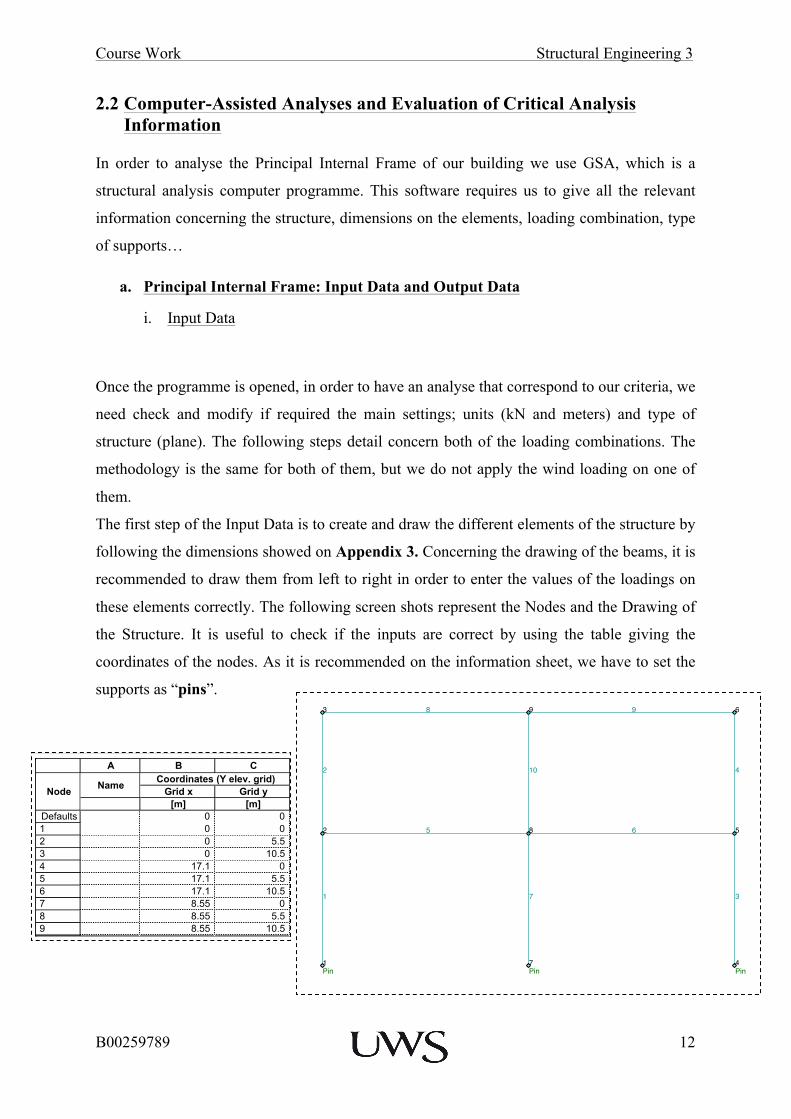
Once the programme is opened, in order to have an analyse that correspond to our criteria, we
need check and modify if required the main settings; units (kN and meters) and type of
structure (plane). The following steps detail concern both of the loading combinations. The
methodology is the same for both of them, but we do not apply the wind loading on one of
them.
The first step of the Input Data is to create and draw the different elements of the structure by
following the dimensions showed on Appendix 3. Concerning the drawing of the beams, it is
recommended to draw them from left to right in order to enter the values of the loadings on
these elements correctly. The following screen shots represent the Nodes and the Drawing of
the Structure. It is useful to check if the inputs are correct by using the table giving the
coordinates of the nodes. As it is recommended on the information sheet, we have to set the
supports as “pins”.
Site License Job No. Sheet No. Rev.
Drg. Ref.
Made by Date Checked
GSA SE3Principal Frame
LJ 13-Oct-2014
Page 1Printed 13-Oct-2014 Time 15:51
Program GSA Version 8.7.0.28 Copyright © Oasys 1985-2014E:\SE 3\Gsa1.gwb
8 9 93 6
102 4
8 52 65
71 3
7Pin
4Pin
1Pin
xy
z
Scale: 1:108.3Labels: Node No.s Elem. No.sHighlighted:Coincident NodesCoincident Elements
Site License Job No. Sheet No. Rev.
Drg. Ref.
Made by Date Checked
GSA SE3Principal Frame
LJ 13-Oct-2014
Page 1Printed 13-Oct-2014 Time 15:50
Program GSA Version 8.7.0.28 Copyright © Oasys 1985-2014E:\SE 3\Gsa1.gwb
A B C D E F G H I J
NodeName
Coordinates (Y elev. grid) Constraint Axis
Restraint Direction Support StiffnessGrid x Grid y x z yy x z yy
[m] [m] [kN/m] [kN/m] [kNm/rad]Defaults 0 0 Global ~ ~ ~ 0 0 01 0 0 Global Yes Yes ~ 02 0 5.5 Global ~ ~ ~ 0 0 03 0 10.5 Global ~ ~ ~ 0 0 04 17.1 0 Global Yes Yes ~ 05 17.1 5.5 Global ~ ~ ~ 0 0 06 17.1 10.5 Global ~ ~ ~ 0 0 07 8.55 0 Global Yes Yes ~ 08 8.55 5.5 Global ~ ~ ~ 0 0 09 8.55 10.5 Global ~ ~ ~ 0 0 0

Course Work Structural Engineering 3
B00259789
13
We can also notice that on my structure that none of the elements have the number 5 or 6,
this is maybe caused by a modification of the structure when it has been drawn but it does not
affect the structure or the analyse as long as it is possible to identify the nature of the
elements and their allocated number.
The next step consists in using the table giving information on each element to change the
property of the beam elements from 1 to 2 because beams and columns don’t have the same
dimensions. On the structure, we can identify that the beam elements are the elements
number 5, 6, 8 and 9.
Now that the elements are identified, we can set up the characteristics of the different
elements (dimensions, nature). The entire structure is made of Concrete Short Term and both
of the elements have rectangular shapes. Once the dimensions are configured, we obtain the
following table:
This table allows us to check if the information corresponds with the dimension of beams and
column we calculated before.
Site License Job No. Sheet No. Rev.
Drg. Ref.
Made by Date Checked
GSA SE3Principal Frame
LJ 13-Oct-2014
Page 1Printed 13-Oct-2014 Time 15:50
Program GSA Version 8.7.0.28 Copyright © Oasys 1985-2014E:\SE 3\Gsa1.gwb
A B C D E F G H
Element Type Property Group Orientation Angle
Topology Dummy wizard1 2
Defaults Beam 1 1 0 0 0 ~1 Beam 1 1 0 1 2 ~ more...2 Beam 1 1 0 2 3 ~ more...3 Beam 1 1 0 4 5 ~ more...4 Beam 1 1 0 5 6 ~ more...5 Beam 2 1 0 2 8 ~ more...6 Beam 2 1 0 8 5 ~ more...7 Beam 1 1 0 7 8 ~ more...8 Beam 2 1 0 3 9 ~ more...9 Beam 2 1 0 9 6 ~ more...10 Beam 1 1 0 8 9 ~ more...
Site License Job No. Sheet No. Rev.
Drg. Ref.
Made by Date Checked
GSA SE3Principal Frame
LJ 09-Oct-2014
Page 1Printed 13-Oct-2014 Time 14:38
Program GSA Version 8.7.0.28 Copyright © Oasys 1985-2014E:\SE 3\Gsa1.gwb
A B C D E
Property Name Material DescriptionAxes for Stiffness
Calculation Area
[m²]Defaults Section # Steel Explicit yz axes 0
1 Column Concrete short term STD R 625. 625. yz axes 0.390632 Beam Concrete short term STD R 625. 450. yz axes 0.28125
Course Work Structural Engineering 3
B00259789
14
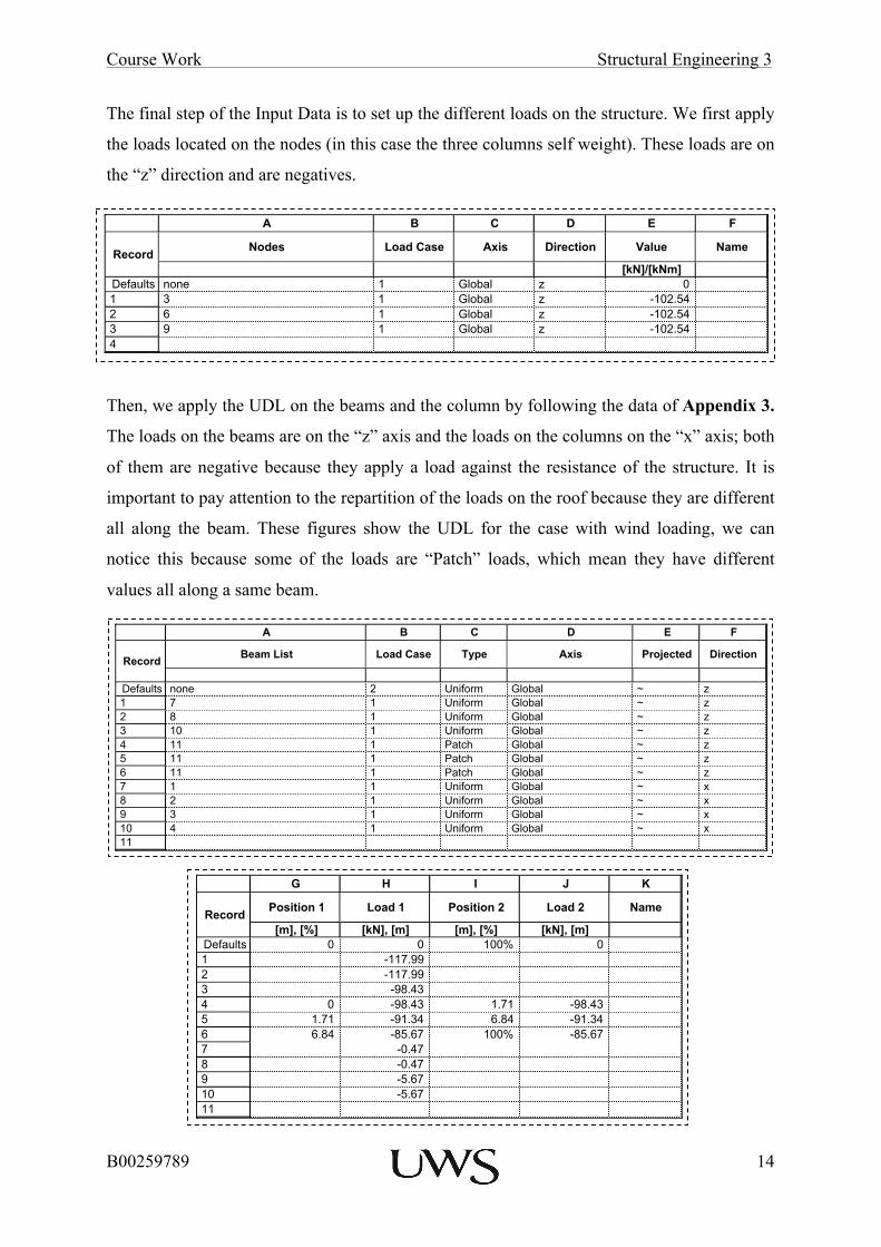
The final step of the Input Data is to set up the different loads on the structure. We first apply
the loads located on the nodes (in this case the three columns self weight). These loads are on
the “z” direction and are negatives.
Then, we apply the UDL on the beams and the column by following the data of Appendix 3.
The loads on the beams are on the “z” axis and the loads on the columns on the “x” axis; both
of them are negative because they apply a load against the resistance of the structure. It is
important to pay attention to the repartition of the loads on the roof because they are different
all along the beam. These figures show the UDL for the case with wind loading, we can
notice this because some of the loads are “Patch” loads, which mean they have different
values all along a same beam.
Site License Job No. Sheet No. Rev.
Drg. Ref.
Made by Date Checked
GSA SE3Principal Frame
LJ 13-Oct-2014
Page 1Printed 13-Oct-2014 Time 15:50
Program GSA Version 8.7.0.28 Copyright © Oasys 1985-2014E:\SE 3\Gsa1.gwb
A B C D E F
Record Nodes Load Case Axis Direction Value Name
[kN]/[kNm]Defaults none 1 Global z 01 3 1 Global z -102.542 6 1 Global z -102.543 9 1 Global z -102.544
Site License Job No. Sheet No. Rev.
Drg. Ref.
Made by Date Checked
GSA SE3Principal Frame
LJ 09-Oct-2014
Page 2Printed 13-Oct-2014 Time 15:07
Program GSA Version 8.7.0.28 Copyright © Oasys 1985-2014E:\SE 3\Gsa1.gwb
G H I J K
Record Position 1 Load 1 Position 2 Load 2 Name
[m], [%] [kN], [m] [m], [%] [kN], [m]Defaults 0 0 100% 01 -117.992 -117.993 -98.434 0 -98.43 1.71 -98.435 1.71 -91.34 6.84 -91.346 6.84 -85.67 100% -85.677 -0.478 -0.479 -5.6710 -5.6711
Site License Job No. Sheet No. Rev.
Drg. Ref.
Made by Date Checked
GSA SE3Principal Frame
LJ 09-Oct-2014
Page 1Printed 13-Oct-2014 Time 15:07
Program GSA Version 8.7.0.28 Copyright © Oasys 1985-2014E:\SE 3\Gsa1.gwb
A B C D E F
Record Beam List Load Case Type Axis Projected Direction
Defaults none 2 Uniform Global ~ z1 7 1 Uniform Global ~ z2 8 1 Uniform Global ~ z3 10 1 Uniform Global ~ z4 11 1 Patch Global ~ z5 11 1 Patch Global ~ z6 11 1 Patch Global ~ z7 1 1 Uniform Global ~ x8 2 1 Uniform Global ~ x9 3 1 Uniform Global ~ x10 4 1 Uniform Global ~ x11

Course Work Structural Engineering 3
B00259789
15
Then, concerning the loading without wind, we can see that the combination is a bit simpler
because we just have uniform loads on the beams, and no loads on the walls.
Once these steps are done properly, we can carry out the analysis of the structure that will tell
us if any errors have been recorded. If no, we can study the different displays given.
Site License Job No. Sheet No. Rev.
Drg. Ref.
Made by Date Checked
GSA SE3Principal Frame
LJ 13-Oct-2014
Page 1Printed 13-Oct-2014 Time 15:53
Program GSA Version 8.7.0.28 Copyright © Oasys 1985-2014E:\SE 3\Gsa1.gwb
8
-98.43
9
102.5
9
-85.67-98.43 -91.34 -91.34-85.67
3
102.5
6
102.5
102-0.4700 4-5.670
8 52 6
-118.0
5
-118.0
71-0.4700 3-5.670
7Pin
4Pin
1Pin
xy
z
Scale: 1:108.3Labels: Node No.s Elem. No.sHighlighted:Coincident NodesCoincident ElementsNode Loads, Force: 100.0 kN/pic.cm Output axis: globalBeam Loads, Force: 100.0 kN/m/pic.cm Output axis: globalCase: L1Case: A1 : Analysis case 1
Site License Job No. Sheet No. Rev.
Drg. Ref.
Made by Date Checked
GSA SE3Principal Frame
LJ 13-Oct-2014
Page 1Printed 13-Oct-2014 Time 15:46
Program GSA Version 8.7.0.28 Copyright © Oasys 1985-2014E:\SE 3\Gsa11.gwb
8
-95.12
9
102.5
9
-95.12
3
102.5
6
102.5
102 4
8 52 6
-118.0
5
-118.0
71 3
7Pin
4Pin
1Pin
xy
z
Scale: 1:152.7Labels: Node No.s Elem. No.sHighlighted:Coincident NodesCoincident ElementsNode Loads, Force: 100.0 kN/pic.cm Output axis: globalBeam Loads, Force: 100.0 kN/m/pic.cm Output axis: globalCase: L1Case: A1 : Analysis case 1

Course Work Structural Engineering 3
B00259789
16
x. Output Data
The output data of GSA allows us to have all the information we need to achieve our design.
In this part, we will compare the two different set of output, with and without wind loadings
and explain what are the main variations.
First, when we do the analysis, we can notice that the deformed shape with wind loadings is
different because the wind adds loads on the wall, which make the structure sway.
Also, the reactions at the support of the structure will be different. The values are more
important with the wind but the main output is that concerning the case without wind, the
internal column doesn’t have any lateral loading.
Site License Job No. Sheet No. Rev.
Drg. Ref.
Made by Date Checked
GSA SE3Principal Frame
LJ 13-Oct-2014
Page 1Printed 13-Oct-2014 Time 15:54
Program GSA Version 8.7.0.28 Copyright © Oasys 1985-2014E:\SE 3\Gsa1.gwb
89
93 6
102 4
8 5265
71 3
7Pin
4Pin
1Pin
xy
z
Scale: 1:108.3Labels: Node No.s Elem. No.sHighlighted:Coincident NodesCoincident ElementsDeformation magnification: 50.00Case: L1Case: A1 : Analysis case 1
Deformed shape with wind loadings
Site License Job No. Sheet No. Rev.
Drg. Ref.
Made by Date Checked
GSA SE3Principal Frame
LJ 13-Oct-2014
Page 1Printed 13-Oct-2014 Time 15:46
Program GSA Version 8.7.0.28 Copyright © Oasys 1985-2014E:\SE 3\Gsa11.gwb
89
93 6
102 4
8 5265
71 3
7Pin
4Pin
1Pin
xy
z
Scale: 1:152.7Labels: Node No.s Elem. No.sHighlighted:Coincident NodesCoincident ElementsDeformation magnification: 50.00Case: L1Case: A1 : Analysis case 1
Deformed shape without wind loadings
Site License Job No. Sheet No. Rev.
Drg. Ref.
Made by Date Checked
GSA SE3Principal Frame
LJ 13-Oct-2014
Page 1Printed 13-Oct-2014 Time 15:53
Program GSA Version 8.7.0.28 Copyright © Oasys 1985-2014E:\SE 3\Gsa1.gwb
8 9 93 6
102 4
8 52 65
71 3
7Pin
20.63
2013.
4Pin-8.426
929.7
1Pin
52.27
1007.
xy
z
Scale: 1:108.3Labels: Node No.s Elem. No.sHighlighted:Coincident NodesCoincident ElementsReaction Force, Fx: 2000. kN/pic.cm Output axis: globalReaction Force, Fy: 0.0 kN/pic.cm Output axis: globalReaction Force, Fz: 2000. kN/pic.cm Output axis: globalCase: L1Case: A1 : Analysis case 1
Reaction at the supports with wind loadings
Site License Job No. Sheet No. Rev.
Drg. Ref.
Made by Date Checked
GSA SE3Principal Frame
LJ 13-Oct-2014
Page 1Printed 13-Oct-2014 Time 15:44
Program GSA Version 8.7.0.28 Copyright © Oasys 1985-2014E:\SE 3\Gsa11.gwb
8 9 93 6
102 4
8 52 65
71 3
7Pin
2005.
4Pin-35.92
973.2
1Pin
35.92
973.2
xy
z
Scale: 1:167.3Labels: Node No.s Elem. No.sHighlighted:Coincident NodesCoincident ElementsReaction Force, Fx: 2000. kN/pic.cm Output axis: globalReaction Force, Fy: 0.0 kN/pic.cm Output axis: globalReaction Force, Fz: 2000. kN/pic.cm Output axis: globalCase: L1Case: A1 : Analysis case 1
Reaction at the supports without wind loadings

Course Work Structural Engineering 3
B00259789
17
However, the main outputs concern the bending moments, shear forces and axial forces on
the different elements of the structure. The major difference is concerning the repartition of
the loading that affects the values of maximum bending moments on the elements. On the
structure without wind loading, because the UDL are symmetrical, the bending moments
have to be symmetrical too. This is a way to check if the values are correct or no.
Concerning the structure with wind loading, we can only check if the output is correct by
comparing the values on the right hand side and the left hand side. Because the UDL are
more important on the left hand side at the roof level, the maximum bending moments should
behave the same. At the Level 1, the values are more important on the right hand side
because we have significant loads on the walls.
Site License Job No. Sheet No. Rev.
Drg. Ref.
Made by Date Checked
GSA SE3Principal Frame
LJ 13-Oct-2014
Page 1Printed 13-Oct-2014 Time 15:43
Program GSA Version 8.7.0.28 Copyright © Oasys 1985-2014E:\SE 3\Gsa1.gwb
8
636.9447.6
-326.9
9 9447.6636.9
-326.9
3 6
102
447.6
-413.4
4
-447.6
413.48 52 6
611.0766.6
-389.4
5
766.6611.0
-389.4
7
0.0
0.0
1
197.6
-10.62E-6
3
-197.6
10.62E-67Pin
4Pin
1Pin
xy
z
Scale: 1:167.3Labels: Node No.s Elem. No.sHighlighted:Coincident NodesCoincident ElementsMoment, Myy: 1000. kNm/pic.cmCase: L1Case: A1 : Analysis case 1
Bending Moment Diagram without wind loadings

Course Work Structural Engineering 3
B00259789
18
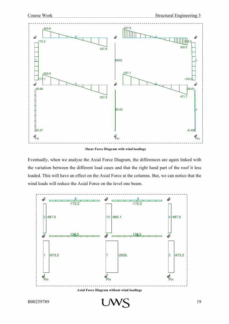
The rest of the significant outputs concern the Shear Force Diagrams. As we noticed for the
other output, in the case of no wind loading, there is no shear force on the middle column due
to symmetrical loading. Also, the wind loading increases the shear force on the left-hand side
of the roof level and on the external columns.
Site License Job No. Sheet No. Rev.
Drg. Ref.
Made by Date Checked
GSA SE3Principal Frame
LJ 13-Oct-2014
Page 1Printed 13-Oct-2014 Time 15:52
Program GSA Version 8.7.0.28 Copyright © Oasys 1985-2014E:\SE 3\Gsa1.gwb
8
630.5484.8
-341.8
9 9409.1
643.8
-309.2
3 6
10
13.32
-2.504
2
484.8
-397.8
4
-409.1
412.58 52 6
544.6824.3
-393.7
5
708.4678.1
-384.9
7
113.5
17.41E-6
1
280.4
-2.776E-6
3
-132.1
5.965E-67Pin
4Pin
1Pin
xy
z
Scale: 1:108.3Labels: Node No.s Elem. No.sHighlighted:Coincident NodesCoincident ElementsMoment, Myy: 1000. kNm/pic.cmCase: L1Case: A1 : Analysis case 1
Bending Moment Diagram with wind loadings
Site License Job No. Sheet No. Rev.
Drg. Ref.
Made by Date Checked
GSA SE3Principal Frame
LJ 13-Oct-2014
Page 1Printed 13-Oct-2014 Time 15:43
Program GSA Version 8.7.0.28 Copyright © Oasys 1985-2014E:\SE 3\Gsa1.gwb
8
428.8
-384.5
9 9
384.5
-428.8
3 6
102 172.2 4-172.2
8 52 6
486.2
-522.6
5
522.6
-486.2
7135.92 3-35.92
7Pin
4Pin
1Pin
xy
z
Scale: 1:167.3Labels: Node No.s Elem. No.sHighlighted:Coincident NodesCoincident ElementsShear Force, Fz: 500.0 kN/pic.cmCase: L1Case: A1 : Analysis case 1
Shear Force Diagram without wind loadings
Course Work Structural Engineering 3
B00259789
19
Eventually, when we analyse the Axial Force Diagram, the differences are again linked with
the variation between the different load cases and that the right hand part of the roof it less
loaded. This will have an effect on the Axial Force at the columns. But, we can notice that the
wind loads will reduce the Axial Force on the level one beam.
Site License Job No. Sheet No. Rev.
Drg. Ref.
Made by Date Checked
GSA SE3Principal Frame
LJ 13-Oct-2014
Page 1Printed 13-Oct-2014 Time 15:52
Program GSA Version 8.7.0.28 Copyright © Oasys 1985-2014E:\SE 3\Gsa1.gwb
8
437.8
-403.8
9 9
355.5
-427.9
3 6
103.1652
175.3
177.7
4
-178.5
-150.28 52 6
471.7
-537.1
5
507.9
-500.9
720.631
49.68
52.27
3
-39.61
-8.4267Pin
4Pin
1Pin
xy
z
Scale: 1:108.3Labels: Node No.s Elem. No.sHighlighted:Coincident NodesCoincident ElementsShear Force, Fz: 500.0 kN/pic.cmCase: L1Case: A1 : Analysis case 1
Shear Force Diagram with wind loadings
Axial Force Diagram without wind loadings
Site License Job No. Sheet No. Rev.
Drg. Ref.
Made by Date Checked
GSA SE3Principal Frame
LJ 13-Oct-2014
Page 1Printed 13-Oct-2014 Time 15:44
Program GSA Version 8.7.0.28 Copyright © Oasys 1985-2014E:\SE 3\Gsa11.gwb
8-172.2
9 9-172.2
3 6
10 -960.12 -487.0 4 -487.0
8 52 6136.35136.3
7 -2005.1 -973.2 3 -973.2
7Pin
4Pin
1Pin
xy
z
Scale: 1:167.3Labels: Node No.s Elem. No.sHighlighted:Coincident NodesCoincident ElementsAxial Force, Fx: 2000. kN/pic.cmCase: L1Case: A1 : Analysis case 1
Course Work Structural Engineering 3
B00259789
20
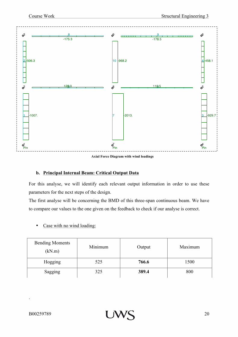
b. Principal Internal Beam: Critical Output Data For this analyse, we will identify each relevant output information in order to use these
parameters for the next steps of the design.
The first analyse will be concerning the BMD of this three-span continuous beam. We have
to compare our values to the one given on the feedback to check if our analyse is correct.
• Case with no wind loading:
.
Bending Moments
(kN.m) Minimum Output Maximum
Hogging 525 766.6 1500
Sagging 325 389.4 800
Site License Job No. Sheet No. Rev.
Drg. Ref.
Made by Date Checked
GSA SE3Principal Frame
LJ 13-Oct-2014
Page 1Printed 13-Oct-2014 Time 15:53
Program GSA Version 8.7.0.28 Copyright © Oasys 1985-2014E:\SE 3\Gsa1.gwb
8-175.3
9 9-178.5
3 6
10 -968.22 -506.3 4 -458.1
8 52 6110.55128.0
7 -2013.1 -1007. 3 -929.7
7Pin
4Pin
1Pin
xy
z
Scale: 1:108.3Labels: Node No.s Elem. No.sHighlighted:Coincident NodesCoincident ElementsAxial Force, Fx: 2000. kN/pic.cmCase: L1Case: A1 : Analysis case 1
Axial Force Diagram with wind loadings

Course Work Structural Engineering 3
B00259789
21
This table confirms that our output is in the required Bending Moments values for the case
without wind loading. Furthermore, we can notice that the values are the same on both sides
because of the symmetrical loading, which also reinforce the veracity of our design.
• Case with wind loading:
This table also confirms that our output is in the required Bending Moments values for the
case with wind loading.
We can use these outputs to have a better understanding of the assumptions we did
concerning the steel reinforcements we draw for the first phase of the design. Like we can see
on these diagrams, the maximum moments are located on the top part of the beam at the
supports, and at the bottom part of the beam at mid-span. But on our assumptions, we put
Bending Moments
(kN.m) Minimum Output Maximum
Hogging 475 824.3 1600
Sagging 325 393.7 800
Site License Job No. Sheet No. Rev.
Drg. Ref.
Made by Date Checked
GSA SE3Principal Frame
LJ 13-Oct-2014
Page 1Printed 13-Oct-2014 Time 15:43
Program GSA Version 8.7.0.28 Copyright © Oasys 1985-2014E:\SE 3\Gsa1.gwb
8
636.9447.6
-326.9
9 9447.6636.9
-326.9
3 6
102
447.6
-413.4
4
-447.6
413.48 52 6
611.0766.6
-389.4
5
766.6611.0
-389.4
7
0.0
0.0
1
197.6
-10.62E-6
3
-197.6
10.62E-67Pin
4Pin
1Pin
xy
z
Scale: 1:167.3Labels: Node No.s Elem. No.sHighlighted:Coincident NodesCoincident ElementsMoment, Myy: 1000. kNm/pic.cmCase: L1Case: A1 : Analysis case 1
Bending Moment Diagram at Level 1 Beam without wind loading
Site License Job No. Sheet No. Rev.
Drg. Ref.
Made by Date Checked
GSA SE3Principal Frame
LJ 13-Oct-2014
Page 1Printed 13-Oct-2014 Time 15:52
Program GSA Version 8.7.0.28 Copyright © Oasys 1985-2014E:\SE 3\Gsa1.gwb
8
630.5484.8
-341.8
9 9409.1
643.8
-309.2
3 6
10
13.32
-2.504
2
484.8
-397.8
4
-409.1
412.58 52 6
544.6824.3
-393.7
5
708.4678.1
-384.9
7
113.5
17.41E-6
1
280.4
-2.776E-6
3
-132.1
5.965E-67Pin
4Pin
1Pin
xy
z
Scale: 1:108.3Labels: Node No.s Elem. No.sHighlighted:Coincident NodesCoincident ElementsMoment, Myy: 1000. kNm/pic.cmCase: L1Case: A1 : Analysis case 1
Bending Moment Diagram at Level 1 Beam with wind loading

Course Work Structural Engineering 3
B00259789
22
bigger bars at mid span than at end. We should have done reversed because the bending
moments are more important near the column.
Secondly, the shear force diagrams of this beam have to be analysed the same way as we did
for the BMD, we need to check if our output are corrects.
• Case with no wind loading:
The output value of the shear force is in the required Shear Forces values for the case without
wind loading. We also notice as we did for the BMD that the values are symmetrical as
expected.
• Case with wind loading:
Shear Force Minimum Output Maximum
(kN) 400 522.6 900
Shear Force Minimum Output Maximum
(kN) 400 537.1 925
Site License Job No. Sheet No. Rev.
Drg. Ref.
Made by Date Checked
GSA SE3Principal Frame
LJ 13-Oct-2014
Page 1Printed 13-Oct-2014 Time 15:43
Program GSA Version 8.7.0.28 Copyright © Oasys 1985-2014E:\SE 3\Gsa1.gwb
8
428.8
-384.5
9 9
384.5
-428.8
3 6
102 172.2 4-172.2
8 52 6
486.2
-522.6
5
522.6
-486.2
7135.92 3-35.92
7Pin
4Pin
1Pin
xy
z
Scale: 1:167.3Labels: Node No.s Elem. No.sHighlighted:Coincident NodesCoincident ElementsShear Force, Fz: 500.0 kN/pic.cmCase: L1Case: A1 : Analysis case 1
Shear Force Diagram at Level 1 Beam without wind loadings

Course Work Structural Engineering 3
B00259789
23
Again, the outputs are in the required Shear Forces values with wind loadings. We also notice
that due to the wind loading, the values on the left hand side of each span is higher.
To conclude this Beam analysis, we study the Axial Forces in both cases. This will help us to
determine the effect of the wind in this type of structure.
Thanks to these two diagrams, we can tell that the wind loading lowers the Axial Force on
this three-span continuous beam.
Site License Job No. Sheet No. Rev.
Drg. Ref.
Made by Date Checked
GSA SE3Principal Frame
LJ 13-Oct-2014
Page 1Printed 13-Oct-2014 Time 15:52
Program GSA Version 8.7.0.28 Copyright © Oasys 1985-2014E:\SE 3\Gsa1.gwb
8
437.8
-403.8
9 9
355.5
-427.9
3 6
103.1652
175.3
177.7
4
-178.5
-150.28 52 6
471.7
-537.1
5
507.9
-500.9
720.631
49.68
52.27
3
-39.61
-8.4267Pin
4Pin
1Pin
xy
z
Scale: 1:108.3Labels: Node No.s Elem. No.sHighlighted:Coincident NodesCoincident ElementsShear Force, Fz: 500.0 kN/pic.cmCase: L1Case: A1 : Analysis case 1
Shear Force Diagram at Level 1 Beam with wind loadings
Axial Force Diagram at Level 1 Beam without wind loadings
Site License Job No. Sheet No. Rev.
Drg. Ref.
Made by Date Checked
GSA SE3Principal Frame
LJ 13-Oct-2014
Page 1Printed 13-Oct-2014 Time 15:44
Program GSA Version 8.7.0.28 Copyright © Oasys 1985-2014E:\SE 3\Gsa11.gwb
8-172.2
9 9-172.2
3 6
10 -960.12 -487.0 4 -487.0
8 52 6136.35136.3
7 -2005.1 -973.2 3 -973.2
7Pin
4Pin
1Pin
xy
z
Scale: 1:167.3Labels: Node No.s Elem. No.sHighlighted:Coincident NodesCoincident ElementsAxial Force, Fx: 2000. kN/pic.cmCase: L1Case: A1 : Analysis case 1
Site License Job No. Sheet No. Rev.
Drg. Ref.
Made by Date Checked
GSA SE3Principal Frame
LJ 13-Oct-2014
Page 1Printed 13-Oct-2014 Time 15:53
Program GSA Version 8.7.0.28 Copyright © Oasys 1985-2014E:\SE 3\Gsa1.gwb
8-175.3
9 9-178.5
3 6
10 -968.22 -506.3 4 -458.1
8 52 6110.55128.0
7 -2013.1 -1007. 3 -929.7
7Pin
4Pin
1Pin
xy
z
Scale: 1:108.3Labels: Node No.s Elem. No.sHighlighted:Coincident NodesCoincident ElementsAxial Force, Fx: 2000. kN/pic.cmCase: L1Case: A1 : Analysis case 1
Axial Force Diagram at Level 1 Beam with wind loadings

Course Work Structural Engineering 3
B00259789
24
3. Computer-Assisted Justification
3.1 Computer-Assisted Justification of the Estimated Design of the Principal Internal Beam
On this part of the design we use the Concrete Centre’s Spreadsheet Programme to design the
appropriate elements. We have to use the output from the previous phases at the Principal
Internal Beam at Level 1. This programme will allow us to design the beam to be adequate in
resisting bending moments, shear forces and the criterion of deflection.
a. Design the beam to be adequate in resisting the selected critical bending moments
The programme requires us to enter the following Input in order to give the correct
reinforcements. For this design phase, we will first check if the assumptions we did on phase
one are correct or no for both loading cases, and eventually change them if required.
Thanks to this figure, we can see that we have to give the following information:
- Maximum moment: Hogging or Sagging depending on the location, refer to phase 2
- Dimensions of the beam: span = 8550mm, h = 450mm, b = 625mm
- Permanent and variable loadings: gk = 52.40 kN/m, qk = 31.50 kN/m (the loadings
are the same for both case)
- Diameters and cover of the bars (The cover is the diameter plus 10 millimetres, for
the side cover, it is required to use the maximum cover)
Required Input for the Concrete Centre’s Programme – Bending Moment

Course Work Structural Engineering 3
B00259789
25
The other parameters:
- Beam type: support or mid-span
- fck = 28 N/mm2 (we have to choose between 28 N/mm2 and 30 N/mm2)
- fyk = 500 N/mm2 (if we choose fck = 28 N/mm2, fyk 500 N/mm2)
- Usage: storage (specified in phase 1, with no brittle partitions)
For each design, once the information is given, the programme will highlight any errors and
give the appropriate bar arrangement.
b. Design the beam to be adequate in resisting the selected critical shear forces The design of the beam to be adequate in resisting critical shear forces follows the same
principle as previously.
We need to enter the following information on the programme:
- fck = 28 N/mm2
- fyk = 500 N/mm2
- Dimensions of the beam: d (can be found on each case on the bending moment
spread sheet of the programme), bw = 625mm.
- Diameter and number of bars: depends on the location of the beam, refers to the
bending moment design.
- Information on the links: diameter (we choose 12mm diameter links), number of
legs (depend on the arrangement of the bars on the bending moment design).
- Loadings: n, correspond to the UDL we use for the BM, and V,Ed, to the value of
the shear force, which is maximal at support and minimal at mid-span.
Required Input for the Concrete Centre’s Programme – Shear Force

Course Work Structural Engineering 3
B00259789
26
c. Design the beam to be adequate in regard with the criterion of “deflection”
Concerning this phase of the design, the criterion on “deflection” concern the L/H checking.
In the first phase of this design, we used this factor to get the dimensions of the beam, where
L is the span between to supports, in our case L = 8550mm, and h, is the height of the beam,
in our case h = 450mm. But, concerning this step, we have to design the criterion of
deflection by using d, the effective depth, instead of h. In the following explanations, the
software calculates the value of d, and the deflections checking are highlighted for the mid-
span location. If we refer to the phase 1, the value had to be between 15 and 23.

Course Work Structural Engineering 3
B00259789
27
3.2 Presentation and Evaluation of the Design Computer Output Information
a. Design the beam to be adequate in resisting the selected critical bending moments
i. No wind loading at support
• Phase 1 assumptions:
If we refer to phase 1, we assumed that the beam would require 5H20 on the tensile part, and
3H25 on the compressive part of the beam. According to the output of the previous phases,
we obtain the following input and output.
BM Output from phase 1 – No wind loading, at support

Course Work Structural Engineering 3
B00259789
28
The output shows that the diameter of the bar is not strong enough because it gives to many
bars on the tension part and specify that the minimum spacing would not be respected.
• Modifications:
Because the first assumption is not correct, we need to change the type of bars we use, we try
with H40 on the tension part and H25 on the compression part.
We obtain 4H25 compression steel and 5H40 tension steel, this arrangement is acceptable but
in order to have an easier arrangement, we add a H25 compression bar to have a symmetrical
arrangement. We could use a smaller diameter but if we use H20, it gives us to many bars
and it would not be suitable.
BM Output with modifications – No wind loading, at support

Course Work Structural Engineering 3
B00259789
29
ii. No wind loading at mid-span
• Phase 1 assumptions:
We obtain, using phase 1 input, the following figure:
We can notice that the reinforcement would be acceptable, the minimum spacing are
respected. But, the design can be improved by using bigger bars on the tension part and
smaller on the compression part.
BM Output from phase 1 – No wind loading, at mid-span
Course Work Structural Engineering 3
B00259789
30
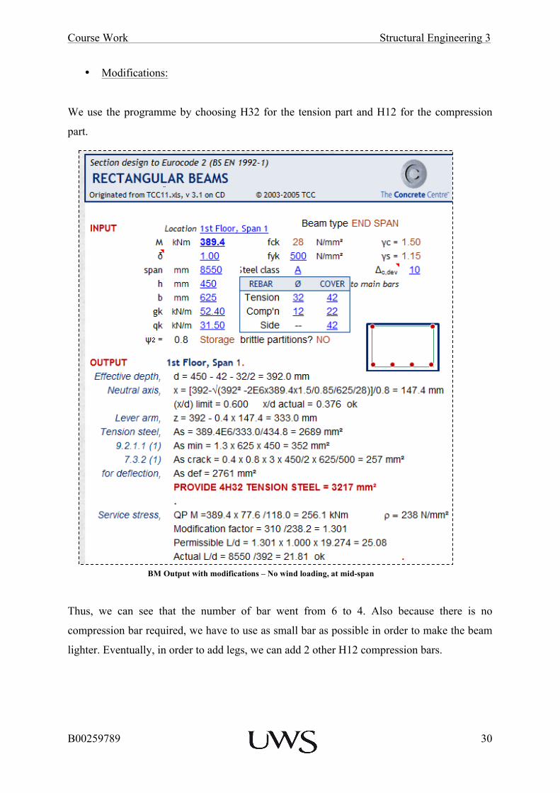
• Modifications:
We use the programme by choosing H32 for the tension part and H12 for the compression
part.
Thus, we can see that the number of bar went from 6 to 4. Also because there is no
compression bar required, we have to use as small bar as possible in order to make the beam
lighter. Eventually, in order to add legs, we can add 2 other H12 compression bars.
BM Output with modifications – No wind loading, at mid-span
Course Work Structural Engineering 3
B00259789
31
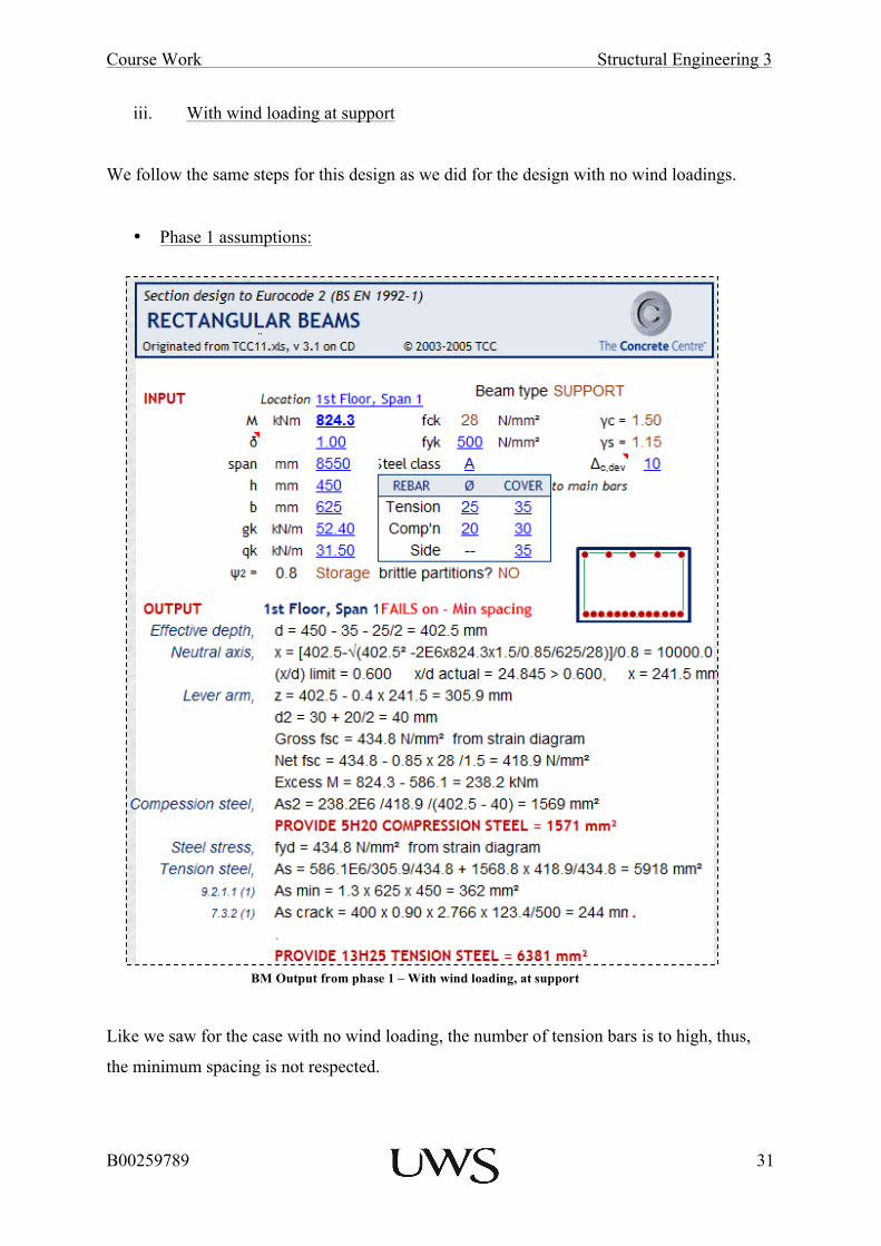
iii. With wind loading at support
We follow the same steps for this design as we did for the design with no wind loadings.
• Phase 1 assumptions:
Like we saw for the case with no wind loading, the number of tension bars is to high, thus,
the minimum spacing is not respected.
BM Output from phase 1 – With wind loading, at support

Course Work Structural Engineering 3
B00259789
32
• Modifications:
In order to lower the number of bars, we use bigger diameters, H40 on tension and H25 on
compression.
This configuration gives us 5H25 compression steel and 5H40 tension steel, which allows us
to add legs if required. In this case we can add one leg on the middle bars.
BM Output with modifications – With wind loading, at support

Course Work Structural Engineering 3
B00259789
33
iv. With wind loading at mid-span
• Phase 1 assumptions:
The assumptions for this design are acceptable, but the number of bars is still high. We have
to improve our design by trying with other bars.
BM Output from phase 1 – With wind loading, at mid-span

Course Work Structural Engineering 3
B00259789
34
• Modifications:
We change the type of bar and use the programme with H32 tension steel and H12
compression steel.
We obtain the same arrangement as the case with no wind loading, 4H32 tension steel. As we
mentioned, we used H12 because this is the diameter of the links we use, thus, we can and
extras if legs are required.
BM Output with modifications – With wind loading, at mid-span

Course Work Structural Engineering 3
B00259789
35
This analysis shows that we have different arrangements according to the different loadings
and locations of the elements. We can see that after modification and final re-arrangements,
we have the same cross sections for both of the case loadings. But in order to make the
fabrication of these beams easier, we decide to take the same overall cover for both of the
location even if the bars are different, which will allows us to have a continuous
reinforcement on the beam. Thus, on the drawings, the side cover will be about 50mm for
both locations.
Course Work Structural Engineering 3
B00259789
36
b. Design the beam to be adequate in resisting the selected critical shear forces
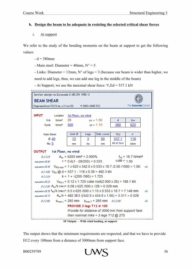
i. At support
We refer to the study of the bending moments on the beam at support to get the following
values:
- d = 380mm
- Main steel: Diameter = 40mm, N° = 5
- Links: Diameter = 12mm, N° of legs = 3 (because our beam is wider than higher, we
need to add legs, thus, we can add one leg in the middle of the beam)
- At Support, we use the maximal shear force: V,Ed = 537.1 kN
The output shows that the minimum requirements are respected, and that we have to provide
H12 every 100mm from a distance of 3000mm from support face.
SF Output – With wind loading, at support

Course Work Structural Engineering 3
B00259789
37
ii. At mid-span
We refer to the study of the bending moments on the beam to get the following values:
- d = 392mm
- Main steel: Diameter = 32mm, N° = 4, steel cover = 32 + 10 = 42mm.
- Links: Diameter = 12mm, N° of legs = 4 (because our beam is wider than higher, we
need to add legs, thus, we also add compression steel, in this case we add 2H12,
because we have H12 steel bars on this part).
Concerning the shear force at mid-span, because it is the minimal, we use the previous table
to see that we need H12 every 300mm. We do not need to do a specific design for this; it
would give us the same output.
The output analysis shows that we will need H12@100mm because the shear force is higher
at support location than at mid-span, thus, the support location is the main design. Also, at
mid span, the spacing will be about 275mm. Finally, these designs will allow us to produce
the drawings. We can notice that we added compression steel at mid-span in order to add
legs, because for this type of beam 2 legs are not meeting the minimum requirements.
Eventually, we chose to modify the spacing between the compression steel at support in order
to align the bottom and the top bars.
Furthermore, we could have tried to lower the links at mid span where the shear force is
minimal but after a few tests, the diameter of the links do not influence the spacing, which
stays at 275 between shear reinforcements. Hence, we keep all links diameter at 12mm,
which make the fabrication easier.
Course Work Structural Engineering 3
B00259789
38
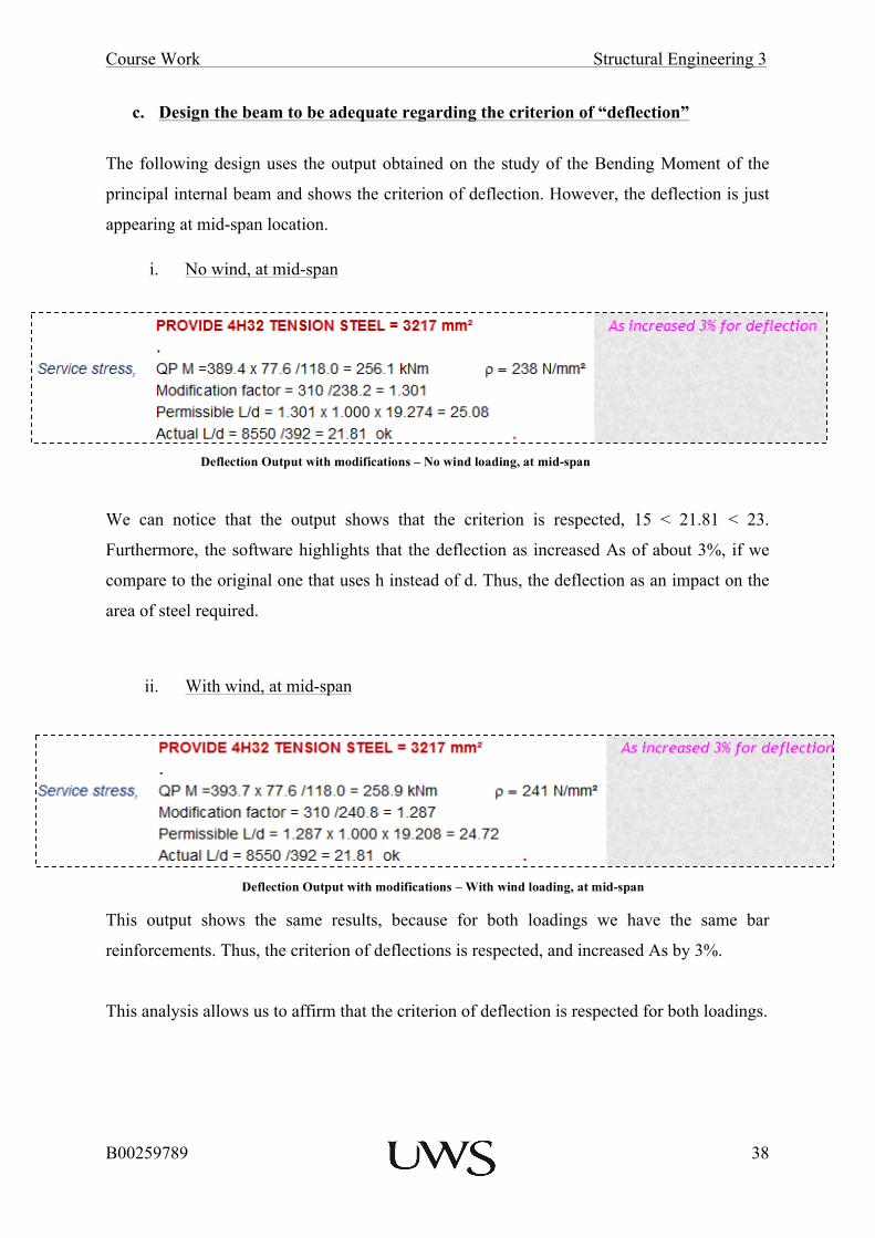
c. Design the beam to be adequate regarding the criterion of “deflection”
The following design uses the output obtained on the study of the Bending Moment of the
principal internal beam and shows the criterion of deflection. However, the deflection is just
appearing at mid-span location.
i. No wind, at mid-span
We can notice that the output shows that the criterion is respected, 15 < 21.81 < 23.
Furthermore, the software highlights that the deflection as increased As of about 3%, if we
compare to the original one that uses h instead of d. Thus, the deflection as an impact on the
area of steel required.
ii. With wind, at mid-span
This output shows the same results, because for both loadings we have the same bar
reinforcements. Thus, the criterion of deflections is respected, and increased As by 3%.
This analysis allows us to affirm that the criterion of deflection is respected for both loadings.
Deflection Output with modifications – No wind loading, at mid-span
Deflection Output with modifications – With wind loading, at mid-span

Course Work Structural Engineering 3
B00259789
39
4. Production of the Final Drawings and Conclusions
4.1 Final Drawings
a. General Arrangements and Detail Drawings
i. Plan Layout at Level 1
This drawing follows the same principal at the plan layout of phase 1, but using the correct dimensions concerning the columns. Refer to Appendix 4.
ii. Principal Internal Structural Frame
On this drawing the principal elements of the Internal Frame are shown, including the columns foundations. Refer to Appendix 5.
iii. Principal Internal Beam at Level 1
Refer to Appendix 6.
b. Reinforcements Detail Drawings
i. Elevation View
The elevation view shows the horizontal element as well as the spacing for the shear links.
The laps, and anchors are calculated following the information drawing given, they are also
shown on the drawings. We also decided to adopt a more specific approach for these
drawings in order to show more details concerning the laps: we show two zoom views at B1
and B2. On the drawing, we can see that for the laps, the H12 and H25 are deviated. We
chose the smaller diameters in order to make the fabrication easier.
Refer to Appendix 7 & 8.

Course Work Structural Engineering 3
B00259789
40
ii. Critical Cross Sections
These cross sections are showing 3 principal critical part of the beam: support, mid-span and
a lap. These drawings do not specify the spacing between the bars, thus we give these values:
Location Spacing
Top Part (mm)
Spacing
Bottom Part (mm)
Mid-Span, 2-2
50 – 12 – 12 – 158.7 – 184.5 -
158.7 – 12 – 12 – 50
= 650mm
50 – 12 – 16 – 164.7 x 3 – 16 – 12 –
50
= 650mm
Support, 3-3
50 – 12 – 20 – 121.5 x 4 – 20 –
12 – 50
= 650mm
50 – 12 – 12.5 – 125.3 – 132.8 –
117.7 – 125.3 – 12.5 – 12 – 50 =
650mm
Laps, 1-1
Spacing are the same instead for the side bars that need to be
displaced (H12 on the top and H25 on the bottom), they are moved to
be stuck to the shear link.
A typical formula would be:
Minimal Cover – Link Diameter – Bar Diameter / 2 – Spacing - Bar Diameter / 2– Link
Diameter – Minimal Cover = Width of the beam.
We can notice that some of the spacing varies. This variation is due to the alignment of the
shear links on the bigger bar elements. Thus it varies on one part to adapt to this alignment.
Refer to Appendix 9.

Course Work Structural Engineering 3
B00259789
41
4.2 Conclusive and Evaluative Report The four phases of this course works allow us to achieve an overall design of this project.
The assumptions and decisions taken are always justified and eventually confirmed during
the next steps of the design.
The first phase allowed us to achieve an overall design of the principal elements of the
structure: beams, columns and slabs. We used simplified method in order to have basics
information to start the calculations of phase 2. We can notice on this part that we did
assumption on the bar arrangements that revealed to be wrong during the other phases. This
might be due to a lack of experience; we should have seen that because we have a long span,
the moment would be critical at support.
For the second phase, we use these assumptions to calculate all the loadings in order to use
them in GSA. We obtain results concerning all the wind, characteristic and variable loadings
on the structure that we use as inputs for GSA. GSA allows us to get the critical values of
bending moments and shear forces on our structure. We can also compare the two load cases,
with and without wind loading. This comparison shows that in our study of the principal
internal frame, the wind has significant effect on the roof and the walls but not on the
principal internal beam that does not show important variations. This phase is critical because
we use all the characteristics of the building (dimensions, loads…) to get the critical moments
we will use in phase 3 for the design of the principal internal beam.
Phase three is a focus on the principal internal beam to show how do we design the
reinforcements using the critical values from the previous designs. We use the Concrete
Centre Spread sheet to determine the horizontal and vertical reinforcements in the beam.
During this phase, we also determined that our assumptions in phase 1 were not accurate and
that bigger elements are required. We optimized the choice of bar diameter and the number of
bar to obtain a final design. The design of beam elements requires logical thinking in term of
feasibility and construction techniques. We have to think about how the beam is built to
chose the correct bar arrangements.
Finally, phase 4 gathers all the principal drawings required to conclude this type of design.
They represent the achievement of the design by showing the main elements. These drawings
have to be accurate and focus on the requirements of the builders/contractors. All the required
information has to be provided, because they do not have to check the calculation details.
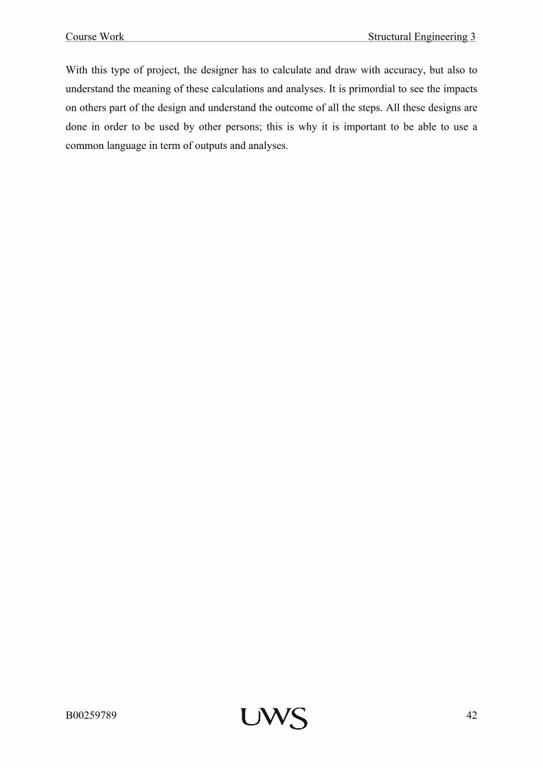
Course Work Structural Engineering 3
B00259789
42
With this type of project, the designer has to calculate and draw with accuracy, but also to
understand the meaning of these calculations and analyses. It is primordial to see the impacts
on others part of the design and understand the outcome of all the steps. All these designs are
done in order to be used by other persons; this is why it is important to be able to use a
common language in term of outputs and analyses.

Course Work Structural Engineering 3
B00259789
43
Appendices
Appendix 1: Floor and Column Plan Layout of Level 1

! !

Course Work Structural Engineering 3
B00259789
44
Appendix 2: Level 1 Slab Section

! !
Leve
l 1 S
lab
Sec
tion
X -
X -
SC
ALE
1:5
0
CB
A
5250
5250
1050
0
450
625
210

Course Work Structural Engineering 3
B00259789
45
Appendix 3: Design Loading Combination at Principal Internal Frame

! !

Course Work Structural Engineering 3
B00259789
46
Appendix 4: Floor and Column Plan Layout of Level 1

! !
A B C
12
3
Col
umn
and
Floo
r Pla
n La
yout
of L
evel
1 (a
fter d
esig
n) -
SC
ALE
: 1:1
005250
5250
1050
0
8550
8550
1710
0
B
PRODUCED BY AN AUTODESK EDUCATIONAL PRODUCTPR
OD
UC
ED B
Y AN
AU
TOD
ESK ED
UC
ATIO
NA
L PRO
DU
CT
PRODUCED BY AN AUTODESK EDUCATIONAL PRODUCT
PRO
DU
CED
BY
AN
AU
TOD
ESK
ED
UC
ATI
ON
AL
PRO
DU
CT

Course Work Structural Engineering 3
B00259789
47
Appendix 5: Cross Section through the Principal Internal Frame
! !
5000
5000
1050
0
500
12
3
450
200
250
2500
1500
625
8550
8550
1710
0
1075
0 Cro
ss S
ectio
n th
roug
h th
e P
rinci
pal I
nter
nal S
truct
ural
Fra
me
- B -
BS
CA
LE: 1
:100
210
PRODUCED BY AN AUTODESK EDUCATIONAL PRODUCTPR
OD
UC
ED B
Y AN
AU
TOD
ESK ED
UC
ATIO
NA
L PRO
DU
CT
PRODUCED BY AN AUTODESK EDUCATIONAL PRODUCTPR
OD
UC
ED B
Y A
N A
UTO
DES
K E
DU
CA
TIO
NA
L PR
OD
UC
T

Course Work Structural Engineering 3
B00259789
48
Appendix 6: Cross Section through the Principal Internal Beam

!!!
! !
A
5250
1050
0
8550
8550
1710
0
625
450
12
3
Cro
ss S
ectio
n of
Prin
cipa
l Int
erna
l Bea
m a
t Lev
el 1
- B -
BS
CA
LE: 1
:100
PRODUCED BY AN AUTODESK EDUCATIONAL PRODUCTPR
OD
UC
ED B
Y AN
AU
TOD
ESK ED
UC
ATIO
NA
L PRO
DU
CT
PRODUCED BY AN AUTODESK EDUCATIONAL PRODUCTPR
OD
UC
ED B
Y A
N A
UTO
DES
K E
DU
CA
TIO
NA
L PR
OD
UC
T
Course Work Structural Engineering 3
B00259789
49
Appendix 7: Elevation View of the Principal Internal Beam – At B-1 Location

! !

Course Work Structural Engineering 3
B00259789
50
Appendix 8: Elevation View of the Principal Internal Beam – At B-2 Location
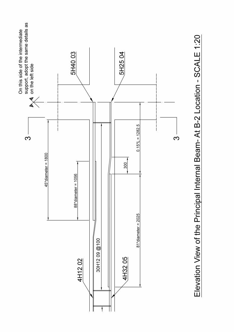
! !

Course Work Structural Engineering 3
B00259789
51
Appendix 9: Critical Cross-Sections along the Principal Internal Beam