structural design solutions for permeable pavementsstructural design solutions for permeable...
TRANSCRIPT

Structural Design Solutions for Permeable Pavements
John Knapton*, David Morrell** & Mihailo Simeunovich**
*John Knapton Consulting Engineers Ltd. (44) 191 2528333
www.john-knapton.com [email protected]
**Marshalls PLC (44) 1422 312000
Landscape House, Elland, UK http://www.marshalls.co.uk
[email protected] [email protected]
Summary
This Paper provides new design guidance for Permeable Pavements. The guidance is based upon many inputs as this Paper explains including, most importantly, the Authors’ 10 years experience of the successful use of the previous design method upon which this new method is based. The Appendix contains the new design solutions in the form of a catalogue of designs. The uniqueness of this design method lies in the way it combines two design methodologies. For lightly trafficked pavements, the loads applied by wheels are the critical factor and the guidance for those pavements is based upon wheel loads. This is known as ultimate load design. For more heavily trafficked highway pavements, the pavements are designed on the basis of the cumulative number of standard 8,000kg axles, in line with the UK Highway Agency design approach. This is known as serviceability design. For pavements trafficked by vehicles applying greater loads than those commonly encountered on highways, the British Ports Association heavy duty pavement design manual (BPA Manual)7 is adopted. This Paper does not provide design sections for such pavements but instead shows how to apply the BPA Manual. The 4th Edition of the BPA Manual can be downloaded from Interpave and includes full guidance on heavy duty permeable pavements. The design tables in this Paper include a reference to the BPA Manual for both Detention Pavements and Infiltration Pavements. This Paper includes tables for the design of Detention Pavements and Infiltration Pavements permeable pavers as shown in Figure 1. Key Words: “Permeable Pavements”, “Pavement Design”, “Elastic Modulus”, “Interlock”, “Herringbone Pattern”, “Dense Bitumen Macadam”, “Hydraulically Bound Material”, “Geogrid”, “Coarse Graded Aggregate”, “British Ports Association”, “Heavy Duty Pavement Design”, “Standard Axle”, “Subgrade”, “Capping”, “Sub-base”, “Temporary Roads”, “Transfer Function”, “Finite Element”, “Subgrade Strain”, “Tensile Strain”, “No-Fines Lean Concrete”,

INTRODUCTION This Paper presents a new structural design method for permeable pavements. It uses effective elastic modulus data for Priora pavers as illustrated in Figure 1. These pavers are of 200mm x 100mm modular size installed to a herringbone pattern. Research has confirmed that this is the preferred laying pattern from a surface stability perspective and also from a load spreading perspective. This paver system has been subjected to full-scale testing which has confirmed that it has excellent interlocking such that an effective elastic modulus of 2,000MPa can be assumed in design1. The Authors have taken this value into account in the development of their design method. Other types of laying patterns can also be used in those pavements trafficked by cars & light vans, vehicles of weight up to 7.5 tonne and occasional emergency large Goods Vehicles. For all other categories of traffic, the arrangement shown in Figure 1 should be used.
Figure 1. Priora Permeable pavers installed in herringbone pattern DERIVATION OF PROPOSED PAVEMENT SECTIONS The Authors have derived the thicknesses and material types within the Tables in the Appendix to this Paper which follow from their consideration of the following sources of information: 1/ From their full-scale testing, the Authors have established that the effective elastic
modulus of the type of pavers shown in Figure 11 is 2,000MPa and from this information they have been able to derive the design methodology which is described in this Paper.
2/ A survey of permeable pavements which have been installed for several years using
the Authors’ previous design method. That survey confirmed that generally the areas are performing well. Appendix 1 shows the design solutions obtained by the Authors’ previous design methods as well as those obtained by their new design method.

3/ Full-scale trafficking trials published at the Buenos Aires International Conference on Concrete Block Paving2 (2009) which showed that in the case of channelization, Dense Bitumen Macadam with 50 Penetration bitumen (DBM50) is a particularly effective roadbase and significantly outperforms Hydraulically Bound Material (HBM), crushed rock and Geogrid-reinforced crushed rock.
4/ The UK Interpave design guide3 and BS 7533: Part 13: 20094. 5/ The US Interlocking Concrete Pavements Institute (ICPI) permeable pavements
design method (Burak RJ & Smith DR)5. This method helps to establish the cut-off in terms of crushed rock based pavements and asphalt based pavements. The ICPI method is based on the well-established AASHTO pavement design method.
6/ The Belgian and German permeable pavement design methods which were described
by Beeldens & Herrier6. These methods extend the use of crushed rock pavements into higher trafficking levels than those proposed by Burak & Smith5. Design methods developed in Germany and Belgium allow fine material in their Coarse Graded Aggregates (CGAs). Those methods rely upon compaction for strength development in CGA. Interpave and ICPI take the opposite approach and rely upon aggregate interlock rather than compaction. This means that in the US and the UK, specifiers need to select aggregates more carefully. The advantage of using coarser crushed rock base materials is that the system does not become clogged but there is a cost penalty. Clogging is a significant issue in Germany and Belgium where it is normal to replace permeable pavers on a regular basis, say every seven years.
7/ Figure 2.1 of UK Highways Agency’s Design Manual for Roads and Bridges (DMRB),
Volume 7, Part 2 which is UK Highways Agency’s design chart for DMB50 and HBM roadbases. The Authors have used this chart to establish thicknesses required for more heavily trafficked pavements, i.e. those in which the design switched from a consideration of the axle weight to the number of repetitions of standard 8,000kg axles.
8/ The Material Equivalence Factors (MEFs) which are set out in the Fourth Edition of
the British Ports Association (BPA) Heavy Duty Pavement Design Manual7. These figures allow one material to be exchanged one for another without detracting from or adding unnecessarily to the performance of the pavement. The Authors have used these factors to swap some of the DMRB asphalt thickness for permeable pavers, i.e. the DBM asphalt thicknesses shown in the tables are reduced by an amount which reflects the structural value of permeable pavers.
9/ The Authors’ own experiences of investigating the performance of pavements of all
types, both in engineering research and as expert witness on a worldwide basis investigating reasons for the failure of pavements.
All of the above factors, when given thoughtful consideration brought the Authors to a position where they considered that the proposed permeable pavement sections were sufficiently robust to justify a full Finite Element check. Having carried out Finite Element analysis of the proposed design solutions, the Authors are able to present the design method in the Appendix to this Paper.

USE OF EXISTING INTERPAVE DESIGN DOCUMENT This Paper does not rework the non-structural parts of the Interpave permeable pavements design manual3 because the Authors consider that the detailed recommendations contained within that document remain valid. For example, they consider that the Interpave material specifications remain correct and that the hydraulic assessments remain valid. However, that document addresses each category of pavement on a fatigue basis. In the Authors’ proposed sections, they have used the ultimate load method for the design of lightly trafficked pavements since the cumulative standard axle approach becomes less realistic when the actual use of the pavement is by a mix of traffic which deviates significantly from standard 8,000kg axles. This applies particularly in the case of those pavements which are trafficked by vehicles having significantly lighter axle loads than the standard axle of 8,000kg, i.e. all vehicles up to and including 7.5tonne vans. INCLUSION OF GEOGRIDS The Authors have addressed the relevance of geogrids. Previous full-scale trials2 showed that geogrids add little to the longevity of pavements trafficked by Large Goods Vehicles (LGVs) in the case of subgrade CBRs of 5% and above. Those trials showed that crushed rocks and geogrid reinforced crushed rocks produced essentially similar rutting and that rutting was much greater than that which occurred in the DBM and HBM test items. However, in the case of lightly trafficked crushed rock pavements, it is likely that the tension which develops within the geogrids will reduce rutting, particularly if aggregate interlock within the Coarse Graded Aggregate (CGA) base is low. For this reason, geogrid reinforced pavements have been included as alternatives within all of the proposed pavements but they allow a saving in course thicknesses only in the case of subgade CBRs of 4% and less. The geogrid options are the even numbered ones in the design tables which follow. The geogrid manufacturer who assisted in this work, has confirmed that they follow UK CIRIA guidance8 which recommends that geogrids are of value only on low CBR soils and that the value increases as the subgrade CBR diminishes. Therefore, the tables include headers which show how using a geogrid effectively lifts the ground conditions by 1% CBR, i.e. when using a geogrid on soils of 4% CBR or less the capping thickness in the case of Detention Pavements or the additional Coarse Graded Aggregate thickness in the case of Infiltration Pavements is as for a 1% higher CBR subgrade. This means that the benefit of geogrids applies only for low CBR soils and the benefit increases with a decrease in CBR which maps correctly onto CIRIA guidance8. This is an approach which the geogrid manufacturers would do well to replicate in all of their design guidance and fits better with the research than the approach currently proposed by some geogrid manufacturers whereby a constant reduction in pavement thickness is allowed by the inclusion of a geogrid, irrespective of sugrade conditions. THE USE OF CAPPING MATERIALS In the case of Detention Pavements, the lowest layer comprises 150mm thickness, or more, of Coarse Graded Aggregate over a waterproof membrane. For pavements of CBR 4% and lower, capping material is included below the waterproof layer. Table 6/2 of Highways Agency’s “Specification for Highway Works”9 describes three types of capping material

according to Particle Size Distribution and material characteristics. The three types are called 6F1, 6F2 and 6F3. Type 6F1 is the finest capping material and all of the particles need to pass the 75mm sieve, whereas in the case of 6F2 and 6F3, up to 65% may be retained on the 75mm sieve. Also, 6F1 material may include up to 15% passing the 63 micron sieve and 6F2/6F3 may include up to 12% passing the 63 micron sieve. 6F3 material has less onerous hardness requirements and is best avoided if possible. 6F2 is the preferred material and is the one most used commonly in the UK. Because all capping materials are allowed to include a significant amount of material passing a 63 micron sieve, they can lose strength when saturated. Therefore, it would not be correct to use them for Infiltration Pavements because such pavements are predicated upon water cascading through each layer of the pavement. Therefore, instead of capping materials, Infiltration Pavements installed over subgrades of 4% or less include additional thickness of Coarse Graded Aggregate which does allow the cascading of water without a strength reduction. Because Coarse Graded Aggregate has superior structural performance to capping materials, the additional thickness of Coarse Graded Aggregate to deal with pavements installed over low CBR subgrades is less than that of capping. For example, in the case of pavements installed over 1% CBR subgrades, Detention Pavements require 600mm of capping placed below a waterproofing layer whereas Infiltration Pavements require an additional 300mm of Coarse Graded Aggregate. DESIGN OF TEMPORARY ROADS SURFACED WITH PERMEABLE PAVERS There are many circumstances when a temporary road is required. This will mainly occur when a builder will need to use a road or other paved surface during the building of the property/properties being served by the road. In this case, the preferred solution is to install the road up to roadbase level using an asphalt referred to in the UK as DBM50, as described in UK Highways Agency’s Specification for Highway Works9 as the roadbase. Before the road enters service as a permeable pavement, 75mm diameter holes need to be formed at 750mm centres in orthogonal directions in order to permit the vertical flow of water. These holes are then filled with 6mm single sized grit before the pavers are installed. In the case of the temporary road, the DBM50 may be trafficked directly by up to 5,000 commercial vehicles prior to the making of the holes and prior to the installation of the pavers. Great care should be taken when trafficking Coarse Graded Aggregate directly. Whether the Coarse Graded Aggregate can accommodate traffic will depend upon the mechanical properties of the particles and there is the possibility that traffic will simply plough through the material. Therefore, as a general recommendation, traffic should not be allowed to travel over Coarse Graded Aggregate directly. Even though such materials may fail very soon when trafficked directly, when the pavers are installed, their weight ensures that there is sufficient friction between individual particles to prevent failure, providing the CGA has been specified correctly. Particularly rounded stones are susceptible to disruption when trafficked directly. Also, directly trafficking CGA can introduce fine material into the voids which can compromise the hydraulic properties of the material.

VALIDATION OF THE PROPOSED DESIGN SECTIONS The above proposed design sections have been checked by carrying out a Finite Element analysis with the purpose of establishing that they each lead provide sufficient protection to the underlying subgrade to endure that rutting will not develop. Also, those pavements which include DBM or HMB have been checked to ensure that fatigue cracking will not occur within those materials. Figure 3 illustrates a typical pattern of strains which develop within a radial vertical plane of an axi-symmetric model using the proprietary Geostudio Finite Element software.
Figure 3. Strains within a permeable pavement produced by the Geostudio Finite Element program. The diagram shows a radial vertical plane of an axi-symmetric 3-D model with the circular patch load applies at the top left which is at the centre of the model. These twin criteria have been checked by comparing the stresses and strains which the Finite Element analysis shows to develop in the subgrade and in the DBM with stresses and strains derived from equations often referred to as Transfer Functions which provide values of the stresses and strains which should not be exceeded within the subgrade and within the sub-base. There are many Transfer Functions available. This is because they are empirical equations which have been derived from observations of the performance of pavements of known material properties. Different authoritative highway administrations, including the UK’s Highways Agency have monitored the performance of their pavements and have thereby derived Transfer Functions appropriate to their own pavements. There is no empirical data available relating the performance of permeable pavements to usage. However, permeable pavements comprise conventional roadbuilding materials whose engineering properties are well understood and there is now a reasonable body of data confirming which pavements have been successful and which have been less successful, such as that collected by the Authors. These sites can be used to run a check on the veracity of the transfer function selected. By this I mean that if the selected Transfer Function produces results in line with Authors’ observations, then it can be considered to be as well validated as the Transfer Functions which are in common use worldwide.

In validating the new design approach, the Authors have selected the most widely used Transfer Functions. These are the following equations which were derived by the US Corps of Engineers. They have been applied by highways agencies in the US and the UK, by Federal Aviation Administration and in the British Ports Association manual for over 25 years and are considered to be well proven. SUBGRADE STRAIN TRANSFER FUNCTION The allowable number of load repetitions is derived from the equation:
Where: N = Number of Repetitions which the pavement can sustain (as established from Finite Element program) A = 0.000247 + 0.000245.Log(Mr) SS = Vertical Strain at upper surface of subgrade Mr = Resilient Modulus of Subgrade (psi) B = 0.0658.Mr
0.559
The relationship between California Bearing Ratio, and Resilient Modulus for the designs being considered is as in Table 1. Table 1. Relationship between California Bearing Ratio and Resilient Modulus
CALIFORNIA BEARING RATIO RESILIENT MODULUS VALUE OF CONSTANT
A
VALUE OF CONSTANT
B PSI N/mm2
1% 1,450 10 0.00102 3.85 2% 2,900 20 0.00110 5.67 3% 4,350 30 0.00114 7.11 4% 5,800 40 0.00117 8.56 5% 7,250 50 0.00119 9.47 20%
(Coarse Graded Aggregate or Capping) 29,000 200
Figure 2 shows the relationship between vertical strain at the surface of the subgrade and the number of repetitions to failure (called “coverages” by CAA to distinguish the figure from aircraft passes). The points on Figure 2 are individual pavements. The four slopes on Figure 2 refer to subgrades of modulus 4,500psi (uppermost line), 9,000psi (blue line), 15,000psi (yellow line) and 22,500psi (lowest line) respectively (approximately 3% CBR, 6% CBR, 10% CBR and 15% CBR).

Figure 4 shows the relationship between number of repetitions and permissible subgrade strain as set out in TRL’s Laboratory Paper LR1132 “The Structural Design of Bituminous Roads” (Powell, Potter, Mayhew & Nunn, 1984)10.
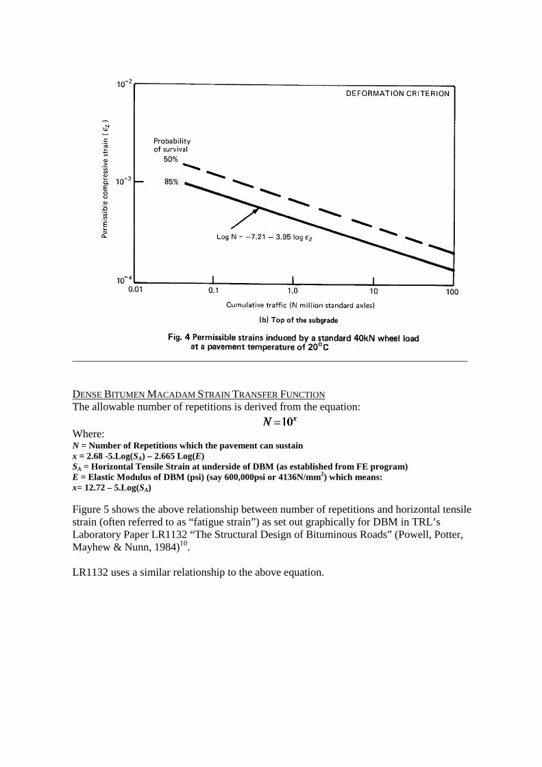
DENSE BITUMEN MACADAM STRAIN TRANSFER FUNCTION The allowable number of repetitions is derived from the equation:
Where: N = Number of Repetitions which the pavement can sustain x = 2.68 -5.Log(SA) – 2.665 Log(E) SA = Horizontal Tensile Strain at underside of DBM (as established from FE program) E = Elastic Modulus of DBM (psi) (say 600,000psi or 4136N/mm2) which means: x= 12.72 – 5.Log(SA)
Figure 5 shows the above relationship between number of repetitions and horizontal tensile strain (often referred to as “fatigue strain”) as set out graphically for DBM in TRL’s Laboratory Paper LR1132 “The Structural Design of Bituminous Roads” (Powell, Potter, Mayhew & Nunn, 1984)10. LR1132 uses a similar relationship to the above equation.

Figure 5 Permissible tensile fatigue strains induced by a standard 40kN wheel load at a pavement temperature of 20°C Using Figures 4 and 5, LR1132 includes the relationship shown in Figure 6 between asphalt thickness and number of wheel patch repetitions.
Figure 6. Relation between thickness and life of roads with Dense Bitumen Macadam roadbase

The following extract from TRL’s LR113210 shows the actual strain relationships used by TRL which differ to a degree from FAA and BPA figures and which take into account the particular characteristics of UK Highways Agency’s DBM. Note that the figures equate to DBM with 100 Penetration bitumen whereas it is now common to use 50 Penetration bitumen. This provides a degree of conservatism in design. For this reason, the FAA fatigue relationships shown in Figure 2 are more appropriate and were used in the Finite Element validation of the design proposals. In the next part of this Paper, the above strain relationships are used to check the proposed designs.
NO FINES LEAN CONCRETE (HYDRAULICALLY BOUND MATERIAL) STRESS TRANSFER FUNCTION For those pavements with a no-fines lean concrete base, proposed thicknesses have been checked by applying limiting tensile stresses occurring within the no-fines lean concrete using the relationships shown below which are taken from the Fourth Edition of the British Ports Association Heavy Duty Pavement Design Manual.
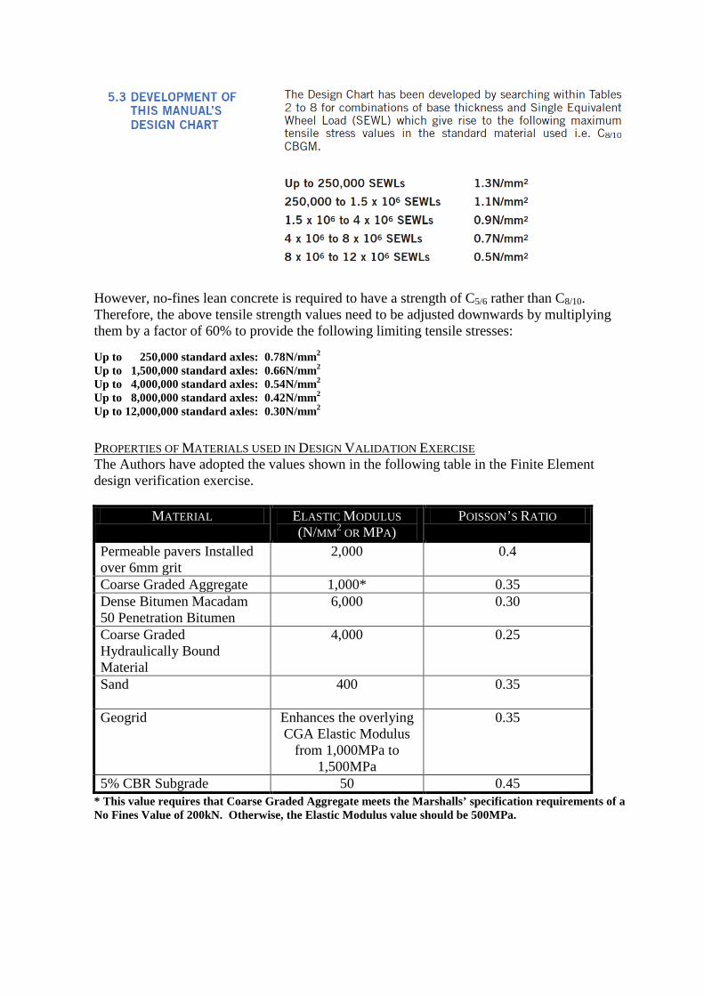
However, no-fines lean concrete is required to have a strength of C5/6 rather than C8/10. Therefore, the above tensile strength values need to be adjusted downwards by multiplying them by a factor of 60% to provide the following limiting tensile stresses:
Up to 250,000 standard axles: 0.78N/mm2 Up to 1,500,000 standard axles: 0.66N/mm2 Up to 4,000,000 standard axles: 0.54N/mm2 Up to 8,000,000 standard axles: 0.42N/mm2 Up to 12,000,000 standard axles: 0.30N/mm2
PROPERTIES OF MATERIALS USED IN DESIGN VALIDATION EXERCISE The Authors have adopted the values shown in the following table in the Finite Element design verification exercise.
MATERIAL ELASTIC MODULUS (N/MM2 OR MPA)
POISSON’S RATIO
Permeable pavers Installed over 6mm grit
2,000 0.4
Coarse Graded Aggregate 1,000* 0.35 Dense Bitumen Macadam 50 Penetration Bitumen
6,000 0.30
Coarse Graded Hydraulically Bound Material
4,000 0.25
Sand
400 0.35
Geogrid Enhances the overlying CGA Elastic Modulus
from 1,000MPa to 1,500MPa
0.35
5% CBR Subgrade 50 0.45 * This value requires that Coarse Graded Aggregate meets the Marshalls’ specification requirements of a No Fines Value of 200kN. Otherwise, the Elastic Modulus value should be 500MPa.

CONCLUSIONS The Authors have established that the design method for permeable pavements presented in this Paper will lead to successful permeable pavements for all of the circumstances covered in this paper. They have shown how data from full-scale testing can be integrated with empirically derived Transfer Function equations and known material properties to produce a robust design approach to permeable pavements. They have included a new approach to introducing the benefits of Geogrids simply by increasing the subgrade California Bearing Ratio by 1% as a means of introducing the benefit of Geogrids into the design system. This has the benefit of ensuring that the well established behavior of Geogrids whereby they have most benefit in the case of low CBR subgrades is included within the design method. Rather than include just one approach to design, as is often the case with design procedures, the Authors have used maximum wheel load ultimate design for more lightly trafficked permeable pavements and have used a conventional standard axle fatigue approach for more heavily trafficked pavements. They have extended the scope of permeable pavements for heavy duty industrial pavements by the application of the British Ports Association heavy duty pavement design method to permeable pavements. A benefit of the design approach is that it allows the designer to select from a wide range of pavement component materials most of which are well establishes having been used in a variety of pavement types for many years. REFERENCES 1. Knapton, Cook & Morrell (2002).“A new design method for permeable pavements
surfaced with pavers” Highways & Transportation, January/February 2002, Pp 23-27. 2. Knapton J & McBride C (2009). “Permeable Pavements for Heavily Trafficked Roads
– A Full Scale Trial” Proc. 9th International Conference on Concrete Block Paving, Buenos Aires, 2009. Argentinean Concrete Block Association.
3. Knapton J & Wilson S (2008). “Guide to the Design, Construction and Maintenance
of Concrete Block Permeable Pavements” Edition 5. Interpave, Leicester, 2008.
4. BS7533: Part 13: 2009. “Pavements constructed with clay, natural stone or concrete pavers. Part 13: Guide for the design of permeable pavements constructed with concrete paving blocks and flags, natural stone slabs and setts and clay pavers”. BSI, London.
5 Burak RJ & Smith DR (2006). “Sustainable Aspects of Segmental Concrete
Pavement”. Proc 8th International Conference on Concrete Block Paving, San Francisco, 2006, Interlocking Concrete Pavement Institute.
6 Beeldens A & Herrier G (2006). “Water Pervious Pavement Blocks: The Belgian
Experience” Proc 8th International Conference on Concrete Block Paving, San Francisco, 2006, Interlocking Concrete Pavement Institute.
7 Knapton J (2007). “The Structural Design of Heavy Duty Pavements for Ports and
Other Industries”, British Ports Association & Interpave, Leicester, 2007.

8 The SUDS Manual (C697) (2007). Construction Industry Research and Information
Association (CIRIA), London, 2007. 9 Manual of Contract Documents for Highway Works. “Specification for Highway
Works” UK Highways Agency, 2012. 10 Powell, Potter, Mayhew & Nunn (1984) TRL Laboratory Report LR1132 “The
Structural Design of Bituminous Roads” TRL, Crowthorne, 1984
APPENDIX PERMEABLE PAVEMENT DESIGN CHARTS

PROPOSED DESIGN SECTIONS FOR DETENTION PERMEABLE PAVEMENTS
The sections in the Table apply in the case of subgrades of 5% CBR or more. For pavements over lower CBR values, replace the 50mm sand with the following: 1% CBR 600mm capping or 300mm capping plus Geogrid 2% CBR 350mm capping or 225mm capping plus Geogrid 3% CBR 225mm capping or 150mm capping plus Geogrid 4% CBR 150mm capping or Geogrid PAVEMENT USE EXISTING
INTERPAVE/BS7533: PART 13 SECTION
EXISTING AUTHORS’ DESIGN SECTION
PROPOSED AUTHORS’ DESIGN SECTION NOTE: A LAYER OF 50MM THICKNESS OF SAND IS INCLUDED IN ALL CASES. THE PURPOSE OF THIS IS TO PROTECT THE WATERPROOF LAYER FROM DAMAGE. IT IS NOT REQUIRED STRUCTURALLY
Pedestrian and Domestic Driveways
80mm pavers 50mm laying course 250mm CGA Waterproof layer 150mm capping
60mm or 80mm pavers 50mm laying course 200mm CGA Waterproof layer 150mm capping
Alternative 1: 60mm or 80mm pavers 50mm laying course 150mm CGA Waterproof layer 50mm sand Alternative 2: 60mm or 80mm pavers 50mm laying course 150mm CGA Geogrid Waterproof layer 50mm sand
Cars & Light Vans
x
80mm pavers 50mm laying course 200mm CGA Waterproof layer 150mm capping
Alternative 1: 60mm or 80mm pavers 50mm laying course 200mm CGA Waterproof layer 50mm sand Alternative 2: 60mm or 80mm pavers 50mm laying course 200mm CGA

Geogrid Waterproof layer 50mm sand
Traffic up to 7.5 tonne x
80mm pavers 50mm laying course 350mm CGA Waterproof layer 150mm capping
Alternative 1: 80mm pavers 50mm laying course 275mm CGA Waterproof layer 50mm sand Alternative 2: 80mm pavers 50mm laying course 275mm CGA Geogrid Waterproof layer 50mm sand
Emergency Large Goods Vehicles only (100 standard axles cumulative)
80mm pavers 50mm laying course 350mm CGA Waterproof layer 150mm capping
80mm pavers 50mm laying course 80mm DBM (100 Pen) 150mm CGA Waterproof layer 150mm capping
Alternative 1: 80mm pavers 50mm laying course 300mm CGA Waterproof layer 50mm sand Alternative 2: 80mm pavers 50mm laying course 300mm CGA Geogrid Waterproof layer 50mm sand
One Large Goods Vehicle per week (0.015msa)
80mm pavers 50mm laying course 125mm coarse HBM 150mm CGA Waterproof layer 150mm capping
x Alternative 1 80mm pavers 50mm laying course 70mm DBM (50 Pen) 150mm CGA Waterproof layer 50mm sand Alternative 2 80mm pavers 50mm laying course 70mm DBM (50 Pen) 150mm CGA Geogrid Waterproof layer

50mm sand Alternative 3 80mm pavers 50mm laying course 100mm coarse HBM 150mm CGA Waterproof layer 50mm sand Alternative 4 80mm pavers 50mm laying course 100mm coarse HBM 150mm CGA Geogrid Waterproof layer 50mm sand
Ten Large Goods Vehicles per week (0.15msa)
80mm pavers 50mm laying course 150mm coarse HBM or 130mm DBM50 150mm CGA Waterproof layer 150mm capping
x
Alternative 1 80mm pavers 50mm laying course 90mm DBM (50 Pen) 150mm CGA Waterproof layer 50mm sand Alternative 2 80mm pavers 50mm laying course 90mm DBM (50 Pen) 150mm CGA Geogrid Waterproof layer 50mm sand Alternative 3 80mm pavers 50mm laying course 125mm coarse HBM 150mm CGA Waterproof layer 50mm sand Alternative 4 80mm pavers 50mm laying course 125mm coarse HBM 150mm CGA
Geogrid Waterproof layer 50mm sand
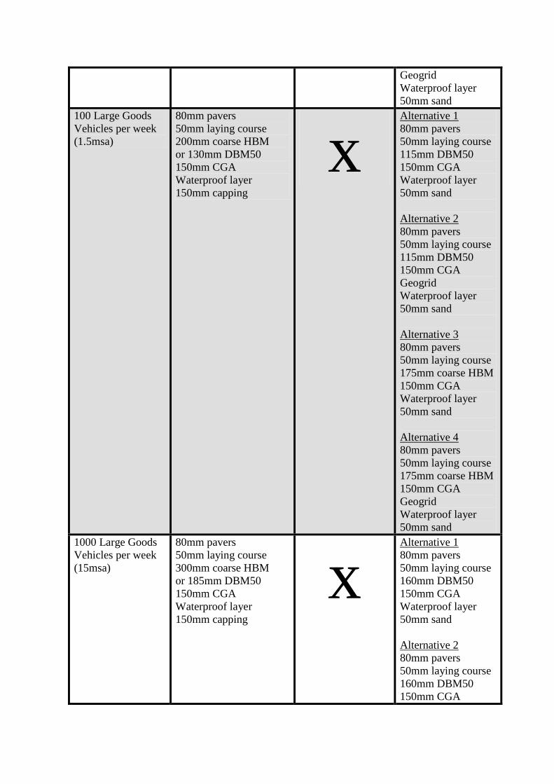
100 Large Goods Vehicles per week (1.5msa)
80mm pavers 50mm laying course 200mm coarse HBM or 130mm DBM50 150mm CGA Waterproof layer 150mm capping
x
Alternative 1 80mm pavers 50mm laying course 115mm DBM50 150mm CGA Waterproof layer 50mm sand Alternative 2 80mm pavers 50mm laying course 115mm DBM50 150mm CGA Geogrid Waterproof layer 50mm sand Alternative 3 80mm pavers 50mm laying course 175mm coarse HBM 150mm CGA Waterproof layer 50mm sand Alternative 4 80mm pavers 50mm laying course 175mm coarse HBM 150mm CGA Geogrid Waterproof layer 50mm sand
1000 Large Goods Vehicles per week (15msa)
80mm pavers 50mm laying course 300mm coarse HBM or 185mm DBM50 150mm CGA Waterproof layer 150mm capping
x
Alternative 1 80mm pavers 50mm laying course 160mm DBM50 150mm CGA Waterproof layer 50mm sand Alternative 2 80mm pavers 50mm laying course 160mm DBM50 150mm CGA

Geogrid Waterproof layer 50mm sand Alternative 3 80mm pavers 50mm laying course 275mm coarse HBM 150mm CGA Waterproof layer 50mm sand Alternative 4 80mm pavers 50mm laying course 275mm coarse HBM 150mm CGA Geogrid Waterproof layer 50mm sand
Heavy Duty Pavements for Ports and similar industries x x
80mm pavers 50mm laying course Coarse HBM or DBM50 thickness to be obtained using the Fourth Edition of the British Ports Association pavement design manual 150mm CGA Waterproof layer 50mm sand
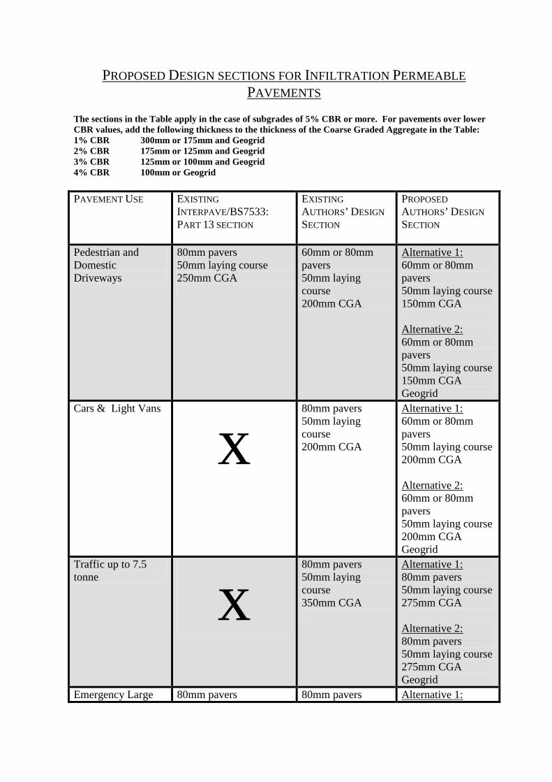
PROPOSED DESIGN SECTIONS FOR INFILTRATION PERMEABLE PAVEMENTS
The sections in the Table apply in the case of subgrades of 5% CBR or more. For pavements over lower CBR values, add the following thickness to the thickness of the Coarse Graded Aggregate in the Table: 1% CBR 300mm or 175mm and Geogrid 2% CBR 175mm or 125mm and Geogrid 3% CBR 125mm or 100mm and Geogrid 4% CBR 100mm or Geogrid PAVEMENT USE EXISTING
INTERPAVE/BS7533: PART 13 SECTION
EXISTING AUTHORS’ DESIGN SECTION
PROPOSED AUTHORS’ DESIGN SECTION
Pedestrian and Domestic Driveways
80mm pavers 50mm laying course 250mm CGA
60mm or 80mm pavers 50mm laying course 200mm CGA
Alternative 1: 60mm or 80mm pavers 50mm laying course 150mm CGA Alternative 2: 60mm or 80mm pavers 50mm laying course 150mm CGA Geogrid
Cars & Light Vans
x
80mm pavers 50mm laying course 200mm CGA
Alternative 1: 60mm or 80mm pavers 50mm laying course 200mm CGA Alternative 2: 60mm or 80mm pavers 50mm laying course 200mm CGA Geogrid
Traffic up to 7.5 tonne x
80mm pavers 50mm laying course 350mm CGA
Alternative 1: 80mm pavers 50mm laying course 275mm CGA Alternative 2: 80mm pavers 50mm laying course 275mm CGA Geogrid
Emergency Large 80mm pavers 80mm pavers Alternative 1:

Goods Vehicles only (100 standard axles cumulative)
50mm laying course 350mm CGA
50mm laying course 80mm DBM (100 Pen) 150mm CGA
80mm pavers 50mm laying course 300mm CGA Alternative 2: 80mm pavers 50mm laying course 300mm CGA Geogrid
One Large Goods Vehicle per week (0.015msa)
80mm pavers 50mm laying course 125mm coarse HBM 150mm CGA x
Alternative 1 80mm pavers 50mm laying course 70mm DBM (50 Pen) 150mm CGA Alternative 2 80mm pavers 50mm laying course 70mm DBM (50 Pen) 150mm CGA Geogrid Alternative 3 80mm pavers 50mm laying course 100mm coarse HBM 150mm CGA Alternative 4 80mm pavers 50mm laying course 100mm coarse HBM 150mm CGA Geogrid
Ten Large Goods Vehicles per week (0.15msa)
80mm pavers 50mm laying course 150mm coarse HBM or 130mm DBM50 150mm CGA
x
Alternative 1 80mm pavers 50mm laying course 90mm DBM (50 Pen) 150mm CGA Alternative 2 80mm pavers 50mm laying course 90mm DBM (50

Pen) 150mm CGA Geogrid Alternative 3 80mm pavers 50mm laying course 125mm coarse HBM 150mm CGA Alternative 4 80mm pavers 50mm laying course 125mm coarse HBM 150mm CGA Geogrid
100 Large Goods Vehicles per week (1.5msa)
80mm pavers 50mm laying course 200mm coarse HBM or 130mm DBM50 150mm CGA
x
Alternative 1 80mm pavers 50mm laying course 115mm DBM50 150mm CGA Alternative 2 80mm pavers 50mm laying course 115mm DBM50 150mm CGA Geogrid Alternative 3 80mm pavers 50mm laying course 175mm coarse HBM 150mm CGA Alternative 4 80mm pavers 50mm laying course 175mm coarse HBM 150mm CGA Geogrid

1000 Large Goods Vehicles per week (15msa)
80mm pavers 50mm laying course 300mm coarse HBM or 185mm DBM50 150mm CGA
x
Alternative 1 80mm pavers 50mm laying course 160mm DBM50 150mm CGA Alternative 2 80mm pavers 50mm laying course 160mm DBM50 150mm CGA Geogrid Alternative 3 80mm pavers 50mm laying course 275mm coarse HBM 150mm CGA Alternative 4 80mm pavers 50mm laying course 275mm coarse HBM 150mm CGA Geogrid
Heavy Duty Pavements for Ports and similar industries x x
80mm pavers 50mm laying course DBM50 or coarse HBM thickness to be obtained using the Fourth Edition of the British Ports Association pavement design manual 150mm CGA