structural classifications of pressure pipe linings
TRANSCRIPT
Structural Classifications of Pressure Pipe LiningsSuggested Protocol for Product Classification
Ideal crop marks
Dedicated to the World’s Most Important Resource ®


© Copyright 2019 American Water Works Association | iii
Structural Classifications of Pressure Pipe LiningsSuggested Protocol for Product Classification
AWWA Committee Report
Table of Contents
1. Introduction . . . . . . . . . . . . . . . . . . . . . . . . . . . . . . . . . . . . . . . . . . . . . . . . . . . . . . . . . . . . . . . 1
2. Acknowledgments . . . . . . . . . . . . . . . . . . . . . . . . . . . . . . . . . . . . . . . . . . . . . . . . . . . . . . . . . 3
3. Referenced Documents . . . . . . . . . . . . . . . . . . . . . . . . . . . . . . . . . . . . . . . . . . . . . . . . . . . . . 4
3.1 ASTM Standards . . . . . . . . . . . . . . . . . . . . . . . . . . . . . . . . . . . . . . . . . . . . . . . . . . . . . 4
3.2 AWWA Standards . . . . . . . . . . . . . . . . . . . . . . . . . . . . . . . . . . . . . . . . . . . . . . . . . . . . . 5
3.3 DIN Standards . . . . . . . . . . . . . . . . . . . . . . . . . . . . . . . . . . . . . . . . . . . . . . . . . . . . . . . 5
3.4 EN Standards . . . . . . . . . . . . . . . . . . . . . . . . . . . . . . . . . . . . . . . . . . . . . . . . . . . . . . . . 5
3.5 ISO Standards . . . . . . . . . . . . . . . . . . . . . . . . . . . . . . . . . . . . . . . . . . . . . . . . . . . . . . . . 6
3.6 NSF/ANSI Standards . . . . . . . . . . . . . . . . . . . . . . . . . . . . . . . . . . . . . . . . . . . . . . . . . . 6
3.7 Other References . . . . . . . . . . . . . . . . . . . . . . . . . . . . . . . . . . . . . . . . . . . . . . . . . . . . . 6
4. Terminology . . . . . . . . . . . . . . . . . . . . . . . . . . . . . . . . . . . . . . . . . . . . . . . . . . . . . . . . . . . . . . . 7
4.1 Definitions . . . . . . . . . . . . . . . . . . . . . . . . . . . . . . . . . . . . . . . . . . . . . . . . . . . . . . . . . . . 7
4.2 Abbreviations . . . . . . . . . . . . . . . . . . . . . . . . . . . . . . . . . . . . . . . . . . . . . . . . . . . . . . . . 8
5. Alignment of Lining Application Requirements With an Owner’s Design Objectives . . . 9
5.1 Problem Definition Statement . . . . . . . . . . . . . . . . . . . . . . . . . . . . . . . . . . . . . . . . . . 9
6. Structural Classifications of Pipelines . . . . . . . . . . . . . . . . . . . . . . . . . . . . . . . . . . . . . . . . 10
6.1 Class I Linings . . . . . . . . . . . . . . . . . . . . . . . . . . . . . . . . . . . . . . . . . . . . . . . . . . . . . . . 10
6.1.1 Typical design objectives . . . . . . . . . . . . . . . . . . . . . . . . . . . . . . . . . . . . . . . . 10
6.1.2 Typical product considerations . . . . . . . . . . . . . . . . . . . . . . . . . . . . . . . . . . . 10
6.2 Class II and III Linings . . . . . . . . . . . . . . . . . . . . . . . . . . . . . . . . . . . . . . . . . . . . . . . . 10
6.2.1 Typical design objectives . . . . . . . . . . . . . . . . . . . . . . . . . . . . . . . . . . . . . . . . 11
6.2.2 Typical product considerations . . . . . . . . . . . . . . . . . . . . . . . . . . . . . . . . . . . 11
6.3 Class IV Linings . . . . . . . . . . . . . . . . . . . . . . . . . . . . . . . . . . . . . . . . . . . . . . . . . . . . . 12
6.3.1 Typical design objectives . . . . . . . . . . . . . . . . . . . . . . . . . . . . . . . . . . . . . . . . 13
6.3.2 Typical product considerations . . . . . . . . . . . . . . . . . . . . . . . . . . . . . . . . . . . 13
7. Structural Classifications Summary . . . . . . . . . . . . . . . . . . . . . . . . . . . . . . . . . . . . . . . . . . 14
8. Testing to Align Problem Definition With Product Selection and Structural Classification . . . . . . . . . . . . . . . . . . . . . . . . . . . . . . . . . . . . . . . . . . . . . . . . . . . . 15
iv | © Copyright 2019 American Water Works Association
List of Tables
Table 1: General Structural Classifications Objectives . . . . . . . . . . . . . . . . . . . . . . . . . . . . . 14
Table 2: Type Testing . . . . . . . . . . . . . . . . . . . . . . . . . . . . . . . . . . . . . . . . . . . . . . . . . . . . . . . . . 15
Table 3: Acceptance Testing . . . . . . . . . . . . . . . . . . . . . . . . . . . . . . . . . . . . . . . . . . . . . . . . . . 18
Table 4: Current Typical Design Approaches . . . . . . . . . . . . . . . . . . . . . . . . . . . . . . . . . . . . . 21
Appendixes
Appendix A—Design Considerations and Future Design Development (Non-mandatory; for Information and Discussion Purposes Only)
© Copyright 2019 American Water Works Association | 1
1. Introduction
The concept of a structural classification system for lining technologies for pressure pipes dates back to work completed by Drs. Jesse Boot, John Heavens, and John Gumbel in the United Kingdom in the late 1990s. It was introduced in
North America in the second edition of AWWA Manual M28 published in 2001 and in the United Kingdom under BS EN 13689: “Guidance on the classification and design of plastics piping systems used for renovation” in 2002. The concept developed was a qualitative one, based on intended function of the lining technology, its degree of interaction with the host pipe, and the type of loads the lining was intended to resist. The identical global, qualitative standard was released as BS EN ISO 11295 in April 2003.
While the qualitative framework has served the industry well to match rehabilitation solutions to known water main problems or deterioration modes, there is a large gap between “qualitative” and “quantitative” objectives as we try to put the classification system into actual practice.
This Committee Report provides an overview on industry consensus of how to transition the AWWA M28 structural classification system from a qualitative concept to a quantitative process of product selection, including initial thoughts on recommended quality assurance processes during construction. Like most problems, the road map is one that will evolve over time as products evolve and one that requires teamwork to resolve in terms of:
y an owner’s ability to articulate the problem to be solved in a manner that allows a designer and/or specialist rehabilitation vendor to match a product to the solution;
y the need for standardized test methods to evaluate a product’s applicability to solve the owner’s problems and to facilitate design;
y the evolution of product development and design methods to match the specific structural classification required; and
y consensus on the types of acceptance tests and quality assurance processes that should be established to reasonably assure that what is installed is consistent with what is needed to resolve the problem, as the long-term viability of most lining technologies is dependent on following proper installation procedures.
2 | © Copyright 2019 American Water Works Association
The issue of design is a complex one, due to both the diversity of products involved and the complexity of factoring in the interaction of lining products with the host pipe and future host pipe deterioration considerations. The content of this Committee Report is intended to be a consensus document focusing on the primary issues of problem definition and quantitative tests to facilitate product system structural classification for pressure pipe renewal applications. An informational Appendix has been included to initiate discussion on design for all lining systems through an illustrative cured-in-place pipe (CIPP) design example to highlight the process of aligning the design process to the specific products being used and the range of loads that need to be considered in a typical lining design based on the owner’s design objectives. Commentary is also included to illustrate the subtle differences that are required to be considered in developing appropriate design models for vastly different products and differing design objectives.
This Committee Report has had the input of a diverse array of practitioners representing a wide range of rehabilitation technologies and various viewpoints in the process from owner to designer to manufacturer to product installers, etc. The intent of the document is to provide a summary of the AWWA M28 Structural Classification System objectives and practical means and methods to shift from a qualitative process to a quantitative one. While individual standards are ultimately required to be developed on a unique technology basis addressing both design and overall quality assurance requirements, the basic process of selecting technology appropriately to solve problems is a universal one, and one that benefits from the common approaches articulated herein.
© Copyright 2019 American Water Works Association | 3
2. AcknowledgmentsThe American Water Works Association (AWWA) Subcommittee on Structural Classifications acknowledges the following individuals who contributed to the review and compilation of this document:
y Dr. Mohammad Najafi, University of Texas at Arlington/CUIRE – Chair of Pipe Rehabilitation Standards Committee
y David P. Kozman, HammerHead Trenchless - Subcommittee Chair
y Chris Macey, AECOM - Subcommittee Vice-Chair
y Dawn M. Flancher, AWWA
y Emily Meek, AWWA
y Lynn E. Osborn, LEO Consulting, LLC
y Randy Cooper, Evanco Environmental Technologies, Inc.
y Dr. Mark Knight, University of Waterloo
y Abu Abraham, AEGION Corp.
y Scott F. Arnold, FYFE Co., LLC
y George J. Bontus, AEGION Corp.
y Michael Davison, Sanexen Environmental Services
y Dan Ellison, HDR Inc.
y Stephane Joseph, Arcuro Inc.
y Steve Leffler, SEKISUI-SPR Americas, Inc.
y Dr. John C. Matthews, Trenchless Technology Center
y Bruce A. Neu, Mott McDonald
y Paul Olson, AWWA
y Keith Oxner, Layne Inc.
y Brian M. Rohan, Rohan Engineering, PC
y Camille George Rubeiz, Plastics Pipe Institute
y William E. Shook, PERMAFORM
y Robert P. Walker, Underground Solutions Inc.
y Matt S. Wassam, SAK Construction
y Kent Weisenberg, SippTech
y Greg J. Welter, O’Brien & Gere
This committee report was consensus approved by the AWWA Standards Committee on Pipe Rehabilitation and the AWWA Standards Council.
4 | © Copyright 2019 American Water Works Association
3. Referenced Documents3.1 ASTM Standards
1 . ASTM C143/C143M, Standard Test Method for Slump of Hydraulic-Cement Concrete
2 . ASTM D638, Standard Test Method for Tensile Properties of Plastics
3 . ASTM D790, Standard Test Methods for Flexural Properties of Unreinforced and Reinforced Plastics and Electrical Insulating Materials
4 . ASTM D1599, Standard Test Method for Resistance to Short-Time Hydraulic Pressure of Plastic Pipe, Tubing and Fittings
5 . ASTM D1784, Standard Specification for Rigid Poly(Vinyl Chloride) (PVC) Compounds and Chlorinated Poly(Vinyl Chloride) (CPVC) Compounds
6 . ASTM D2290, Standard Test Method for Apparent Hoop Tensile Strength of Plastic or Reinforced Plastic Pipe
7 . ASTM D2412, Standard Test Method for Determination of External Loading Characteristics of Plastic Pipe by Parallel-Plate Loading
8 . ASTM D2837, Standard Test Method for Obtaining Hydrostatic Design Basis for Thermoplastic Pipe Materials or Pressure Design Basis for Thermoplastic Pipe Products
9 . ASTM D2990, Standard Test Methods for Tensile, Compressive, and Flexural Creep and Creep-Rupture of Plastics
10 . ASTM D2992, Standard Practice for Obtaining Hydrostatic or Pressure Design Basis for ‘Fiberglass’ (Glass-Fiber-Reinforced Thermosetting-Resin) Pipe and Fittings
11 . ASTM D3039/D3039M, Standard Test Method for Tensile Properties of Polymer Matrix Composite Materials
12 . ASTM D3350, Standard Specification for Polyethylene Plastics Pipe and Fittings Materials
13 . ASTM D3567, Standard Practice for Determining Dimensions of ‘Fiberglass’ (Glass-Fiber-Reinforced Thermosetting Resin) Pipe and Fittings
14 . ASTM D4541, Standard Test Method for Pull-Off Strength of Coatings Using Portable Adhesion Testers
15 . ASTM D7234, Standard Test Method for Pull-Off Adhesion Strength of Coatings on Concrete Using Portable Pull-Off Adhesion Testers
16 . ASTM F1216, Standard Practice for Rehabilitation of Existing Pipelines and Conduits by the Inversion and Curing of a Resin-Impregnated Tube
17 . ASTM F585, Standard Guide for Insertion of Flexible Polyethylene Pipe Into Existing Sewers
18 . ASTM F2164, Standard Practice for Field Leak Testing of Polyethylene (PE) and Crosslinked Polyethylene (PEX) Pressure Piping Systems Using Hydrostatic Pressure
19 . ASTM F2994, Standard Practice for Utilization of Mobile, Automated, Cured-In-Place Pipe (CIPP) Impregnation Systems
20 . ASTM F3182, Standard Practice for the Application of Spray-Applied Polymeric Liners Inside Pipelines for Potable Water
© Copyright 2019 American Water Works Association | 5
3.2 AWWA Standards1 . AWWA Manual of Water Supply Practices M9, Concrete Pressure Pipe, Third Edition
2 . AWWA Manual of Water Supply Practices M23, PVC Pipe – Design and Installation, Second Edition
3 . AWWA Manual of Water Supply Practices M28, Rehabilitation of Water Mains, Third Edition
4 . AWWA Manual of Water Supply Practices M45, Fiberglass Pipe Design, Third Edition
5 . AWWA Manual of Water Supply Practices M55, PE Pipe – Design and Installation
6 . ANSI/AWWA C305, CFRP Renewal and Strengthening of Prestressed Concrete Cylinder Pipe (PCCP)
7 . ANSI/AWWA C602, AWWA Standard for Cement-Mortar Lining of Water Pipelines in Place – 4 in (100 mm) and Larger
8 . ANSI/AWWA C605, Underground Installation of Polyvinyl Chloride (PVC) and Molecularly Oriented Polyvinyl Chloride (PVCO) Pressure Pipe and Fittings
9 . ANSI/AWWA C620, Spray-In-Place Polymeric Lining for Potable Water Pipelines 4 In. (100 mm) and Larger
10 . ANSI/AWWA C651, Disinfecting Water Mains
11 . ANSI/AWWA C900, Polyvinyl Chloride (PVC) Pressure Pipe and Fabricated Fittings, 4 In. Through 60 In. (100 mm Through 1500 mm), for Water Transmission and Distribution
12 . ANSI/AWWA C906, Polyethylene (PE) Pressure Pipe and Fittings, 4 In. Through 65 In. (100 mm Through 1,650 mm), for Waterworks
3.3 DIN Standards1 . DIN EN 761, Plastics Piping Systems – Glass-Reinforced Thermosetting Plastics
(GRP) Pipes – Determination of the Creep Factor Under Dry Conditions
2 . DIN EN 1228, Plastics Piping Systems – Glass-Reinforced Thermosetting Plastics (GRP) Pipes – Determination of Initial Specific Ring Stiffness
3.4 EN Standards1 . EN 13689 (2002), Guidance on the Classification and Design
of Plastics Piping Systems Used for Renovation, CEN, European Committee for Standardisation, Brussels
6 | © Copyright 2019 American Water Works Association
3.5 ISO Standards1 . ISO 178, Plastics – Determination of Flexural Properties
2 . ISO 899-1, Plastics - Determination of Creep Behaviour – Part 1: Tensile Creep
3 . ISO 899-2, Plastics – Determination of Creep Behaviour – Part 2: Flexural Creep by Three-Point Loading
4 . ISO 7432, Glass-Reinforced Thermosetting Plastics (GRP) Pipes and Fittings – Test Methods to Prove the Design of Locked Socket-and-Spigot Joints, Including Double-Socket Joints, With Elastomeric Seals
5 . ISO 7509, Plastics Piping Systems – Glass Reinforced Thermosetting Plastics (GRP) Pipes – Determination of Time to Failure Under Sustained Internal Pressure
6 . ISO 7684, Plastics Piping Systems – Glass Reinforced Thermosetting Plastics (GRP) Pipes – Determination of the Creep Factor Under Dry Conditions
7 . ISO 7685, Plastics Piping Systems – Glass Reinforced Thermosetting Plastics (GRP) Pipes – Determination of Initial Specific Ring Stiffness
8 . ISO 8513, Plastics Piping Systems – Glass-Reinforced Thermosetting Plastics (GRP) Pipes – Test Methods for the Determination of the Initial Longitudinal Tensile Strength
9 . ISO 8521, Plastics Piping Systems – Glass-Reinforced Thermosetting Plastics (GRP) Pipes – Test Methods for the Determination of the Apparent Initial Circumferential Tensile Strength
10 . ISO 8533, Glass-Reinforced Thermosetting Plastics (GRP) Pipes and Fittings – Test Methods to Prove the Design of Cemented or Wrapped Joints
11 . ISO 10468, Glass-Reinforced Thermosetting Plastics (GRP) Pipes – Determination of the Long-Term Specific Ring Creep Stiffness Under Wet Conditions and Calculation of the Wet Creep Factor
12 . ISO 10928, Plastics Piping Systems – Glass-Reinforced Thermosetting Plastics (GRP) Pipes – Methods for Regression Analysis and Their Use
13 . ISO 11296-4, Plastics Piping Systems for Renovation of Underground Non-Pressure Drainage and Sewerage Networks, Part 4: Lining with Cured-In-Place Pipes
14 . ISO 11297-1, Plastics Piping Systems for Renovation of Underground Drainage and Sewerage Networks Under Pressure – Part 1: General
15 . ISO 11297-4, Plastics Piping Systems for Renovation of Underground Drainage and Sewerage Networks Under Pressure – Part 4: Lining With Cured-in-Place Pipes
3.6 NSF/ANSI Standards1 . NSF/ANSI Standard 61: Drinking Water System Components – Health Effects
3.7 Other References1 . Plastics Pipe Institute (PPI) TR-3, Policies and Procedures for Developing Hydrostatic
Design Basis (HDB), Pressure Design Basis (PDB), Strength Design Basis (SDB), and Minimum Required Strength (MRS) Ratings for Thermoplastic Piping Materials or Pipe
2 . Plastics Pipe Institute (PPI) TR-4, PPI Listing of Hydrostatic Design Basis (HDB), Hydrostatic Design Stress (HDS), Strength Design Basis (SDB), Pressure Design Basis (PDB) and Minimum Required Strength (MRS) Ratings for Thermoplastic Piping Materials or Pipe
3 . Plastic Pipe Institute, Handbook of Polyethylene Pipe, Second Edition
4 . Performance Pipe Technical Note 813-TN, PE Pressure Water Piping Systems Mechanical Restraint and Poisson Effects

© Copyright 2019 American Water Works Association | 7
4. Terminology4.1 Definitions
1 . Acceptance Test – A test or a series of tests conducted under actual or simulated field conditions to determine whether a material system or component conforms to specified requirements in a construction or procurement document.
2 . Demonstration Test – A Type or Acceptance Test carried out to demonstrate cause and effect by specified methods; used to establish the relationship between a specific set of procedures to prepare and apply a product and a desired outcome in terms of achieving target mechanical or other properties. For example, building a test panel to illustrate what combination of surface preparation and application technique/procedures are required to achieve target adhesion values.
3 . External Load – Loads on a buried pipeline due to earth pressure, static or fluctuating groundwater levels, or other non-dynamic loading sources.
4 . Live Load – Dynamic loads on a buried pipeline due to vehicles, railways, or aircraft.
5 . Loads Due to Thermal Effects – Load-induced shear effects due to thermal expansion and contraction of the pipe lining system or bonded lining materials.
6 . Long-Term Hoop Strength – The tensile capacity of a material, measured in the circumferential direction, after continuous service of a pressure pipe over an extended period (typically 10,000-h laboratory values extrapolated out to 50 years).
7 . Material Resistance Adjustment Factor – Factors that define the expected end use condition in terms of the values obtained in Type Testing either due to the difference between controlled laboratory and actual or simulated field conditions or due to long-term applied load effects where direct testing is unavailable.
8 . Maximum Allowable Operating Pressure (MAOP) – The maximum anticipated sustained internal operating pressure that a pipe system or lining is anticipated to be exposed to.
9 . Maximum Allowable Pressure (MAP) – The maximum combination of internal pressures that a pipe or lining system is anticipated to be exposed to including sustained, occasional surge and/or test pressure.
10 . Occasional Surge (Emergency or Transient) Pressure – Short-term internal pressure events usually caused by emergency operations of the pipe network system (e.g., a rapid valve closure) or malfunction (e.g., power failure, component failure, etc.)
11 . Pressure Rating Factor (PRF) – Design factor used to estimate the long-term pressure rating of a lining system relative to short-term test results.
12 . Recurring (Cyclic) Surge Pressure – Internal surge pressures that occur frequently and are inherent to the design and operation of the pipe network system (such as normal pump start-up or shutdown and normal valve opening or closure). Recurring surge pressure may occur millions of times in a piping system’s lifetime when constant speed pumps are used in transmission applications. Recurring surge is not common when variable speed pumps are used or in normal water main distribution applications.
13 . Short-Term Hoop Strength – Initial tensile capacity of a material, measured in the circumferential direction.
14 . Type Test – A test carried out under controlled laboratory conditions to demonstrate representative short or long-term structural properties of a product or one of its components.

8 | © Copyright 2019 American Water Works Association
4.2 Abbreviations1 . C = Hazen-Williams Coefficient
2 . CFL = Close-fit lining
3 . CFRP = Carbon fiber reinforced polymer
4 . CIPP = Cured-in-place pipe
5 . CML = Cement mortar lining
6 . DR = Dimension ratio
7 . FRP = Fiber reinforced polymer or plastic composite consisting of thermosetting resin and fiberglass, carbon fiber or other reinforcing agents, or combination thereof
8 . HDB = Hydrostatic Design Basis
9 . HDPE = High-density polyethylene
10 . LRFD = Load and resistance factor design
11 . PL = Polymer lining (spray-on; includes epoxy, polyurea, and polyurethanes)
12 . PVC = Polyvinyl chloride
13 . SL = Sliplining

© Copyright 2019 American Water Works Association | 9
5. Alignment of Lining Application Requirements With an Owner’s Design Objectives
Matching and verifying lining system products to their specific structural classifications will vary widely with their intended application and the specific design objectives. For example, lining systems that may be considered as
acceptable products at one level of Structural Classification, under a specific set of operating and exposure conditions, may be classified at lower or higher Structural Classification levels under markedly different sets of operating and exposure conditions.
Verification that a specific lining system meets the required Structural Classification on a project-specific basis should generally follow this three-step process:
5.1 Problem Definition StatementDefine the objectives of the lining project in terms of a problem statement and specific design requirements including a summary of:
1 . The host pipe description (material, year of manufacture, diameter, wall thickness, pressure class, joint type, etc.), horizontal/vertical alignment, the major deficiencies and deterioration mechanisms intended to be addressed and general chemistry of the fluid to be conveyed.
2 . All relevant internal pressures to be resisted by the lining system including MAP, MAOP, occasional surge, recurrent surge (if applicable), vacuum pressures (if applicable) and the intended magnitude and duration of the test pressure.
3 . All relevant external loads to be resisted by the lining system including the load duration where relevant (e.g., earth and groundwater loads with design duration if not intended to be long-term loading; and live loads—implied short-term duration unless otherwise stated).
4 . Practical design considerations to meet functional requirements of the lining system such as the requirement to reinstate water services in a manner that does not compromise the overall hydrostatic integrity of the system.
5 . The nature of the failure mode of the host pipe to be considered in design in instances where a Class IV Structural Classification is desired.
Select the appropriate suite of Type Tests and material resistance adjustment factors that are required to meet the design objectives from the Problem Definition Statement to facilitate the design and product selection process.
Select the appropriate suite of Acceptance Tests to verify, in the construction phase, that the design objectives have been achieved.
10 | © Copyright 2019 American Water Works Association
6. Structural Classifications of Pipelines
The following general structural classification systems have been previously defined in AWWA M28, with expanded definitions and design objectives provided for additional guidance.
6.1 Class I LiningsClass I linings are essentially nonstructural systems used primarily to protect the inner surface of the host pipe from corrosion and/or improve or maintain water quality. They are not intended to improve the structural performance of the host pipe and have a minimal ability to bridge any existing discontinuities, such as corrosion holes, cracks, or joint gaps. Hence, they usually have minimal effect on reduction or elimination of existing leakage. Their use is indicated in pipes that have internal corrosion or tuberculation but are still in structurally sound condition and where current or future leakage is not the primary design objective.
6.1.1 Typical design objectives1 . To protect the host pipe from internal corrosion and the formation of future
corrosion by-products and to be resistant to any deleterious reaction with the fluid being conveyed for the stipulated design life objective.
2 . To rely on the host pipe to provide all internal and external load resistance, with any specified vacuum loads addressed through reliable adhesion to the host pipe (in PL) or inherent ring stiffness (CML).
3 . To consider the lining’s effect on system hydraulics and operational requirements.
6.1.2 Typical product considerations1 . Un-bonded and bonded lining products such as CML or PL, respectively.
2 . Demonstrated chemical resistance to the fluid being conveyed and adequate stiffness or adhesion to the host pipe to remain intact when pressurized and dewatered and/or to resist vacuum loads when specified.
3 . PL should be free of holidays and blisters.
6.2 Class II and III LiningsClass II and III linings are both interactive and semi-structural systems. When installed, Class II linings shall adhere to the wall of the host pipe. Class III linings may or may not achieve reliable adhesion to the host pipe but shall be sealed to establish or maintain hydrostatic integrity. Since the pressure rating and stiffness of such a lining is less than that of the host pipe, some internal pressure loads are transferred to the host pipe, leading to their classification as interactive. Class II and III linings are required to independently sustain internal pressure loads at existing or future discontinuities in the host pipe, such as corrosion pits, holes, or joint gaps.
A lining system is considered to be Class II or III if its long-term internal burst strength, when tested independently from the host pipe, is less than the MAOP of the pipeline to be rehabilitated. Such a lining would not be expected to survive a burst failure of the host pipe, so it cannot be considered as Class IV. Class II and III linings also rely on the host pipe for bending stresses due to external loads and soil movements. However, Class II and III linings are designed to bridge holes and gaps in the host pipe on a long-term
© Copyright 2019 American Water Works Association | 11
basis, and various systems can be further classified in terms of the magnitude of the holes and gaps they can bridge at any given MAP.
The separation of these systems for spanning holes and gaps into two classes is based on their inherent resistance to external buckling forces, internal pressures, and dependence on reliable adhesion to the host pipe wall. Class II systems have minimal inherent ring stiffness and depend entirely on adhesion to the pipe wall to prevent collapse if the pipe is depressurized. Class III linings have sufficient inherent ring stiffness to be at least self-supporting when depressurized without dependence on adhesion to the pipe wall.
Class III linings can also be designed to independently resist specified external hydrostatic or vacuum loads while Class II linings must develop sufficient adhesion with the host pipe to resist hydrostatic or buckling loads.
6.2.1 Typical design objectives1 . To protect the host pipe from internal corrosion and the formation of future
corrosion by-products and to be resistant to any deleterious reaction with the fluid being conveyed for the stipulated design life objective.
2 . To prevent any leakage occurring from the host pipe at pinholes, holes, and/or faulty joints.
3 . To accommodate further external deterioration of the host pipe by providing sufficient hole spanning capability to meet future conditions. The lining is not intended to arrest external deterioration or provide sufficient reinforcement to resist a full hoop stress failure of the host pipe.
6.2.2 Typical product considerations1 . A wide array of lining systems including all CFLs (CIPP, deformed
and compression fit linings), SL, PL, and CFRP systems have been used dependent on their ability to fully address the Problem Definition Statement requirements and meet design objectives.
2 . Demonstrated chemical resistance to the fluid being conveyed.
3 . Adequate structural properties based on Type Tests that meet the long-term design objectives for hole-spanning applications.
4 . Adequate means to resist all hydrostatic and, if specified, vacuum loads based on either reliable adhesion for Class II products or inherent ring stiffness for Class III products.

12 | © Copyright 2019 American Water Works Association
6.3 Class IV LiningsClass IV linings, termed fully structural or structurally independent, possess the following characteristics:
1 . Long-term hoop strength, when tested independently from the host pipe, equal to or greater than the strength required to withstand the MAOP of the host pipe.
2 . Short-term hoop strength, when tested independently from the host pipe, equal to or greater than the strength required to withstand all anticipated short-term loads, such as negative pressures, occasional and recurrent surge pressures, and live loads.
3 . The ability to survive the full range of anticipated failure modes of the host pipe without leakage or consequential damage to the lining.
Class IV linings are, for the most part, considered to be a structurally equivalent replacement pipe, although such linings may not be designed to meet the same requirements for external buckling and longitudinal bending as the original host pipe. Class IV linings are designed with adequate load resistance and safety factor for all reasonably anticipated loads independent of the host pipe. By necessity, they will have a smaller internal diameter than the host pipe; however, their design should consider uncompromised maintenance of the service objectives of the host pipe such as the reinstatement of service laterals (see AWWA M28, Chapter 11).
Class IV linings can also be used in circumstances similar to those for Class II and III, but their use is essential for host pipes where the long-term deterioration is reasonably expected to compromise the host pipe’s structural performance. Pipe rehabilitation technologies can be categorized as Class II, III, or IV linings as determined by their strength relative to the MAOP and other structural demands of the host pipeline. Varying the MAOP and/or structural demands can change the structural classification of a specific product, dependent on the application.
Similar to operating pressure requirements, the potential failure modes of the host pipe in conjunction with the specific lining product characteristics can also impact a lining’s ability to meet the technical objectives of Class IV. Where brittle fractures of host pipes can be anticipated, owners need to carefully consider whether the lining can withstand a host pipe fracture. Linings with a high degree of chemical, mechanical, and/or frictional bond with the host pipe typically are prone to cracking when the host pipe fails in a brittle fracture mode. For cast iron, asbestos cement, and some other types of water mains, brittle circumferential fractures are a common mode of failure. No lining should be presumed to have the properties required of a Class IV lining (i.e., long-term strength, water tightness, and ability to survive a host pipe failure) without evidence, including testing that reasonably simulates the conditions expected to exist in an aging, pressurized water main that has been lined in place.

© Copyright 2019 American Water Works Association | 13
However, once a Class IV lining has been installed, depending on the internal pressure, host pipe material and Class IV product used, the host pipe may be shielded from internal pressures and leakage inherent in deteriorated pipes. In many cases, the lining will provide reinforcement against failure from external loads, thereby reducing the likelihood of a host pipe failure and, in arresting leakage, supplement ground movement that would otherwise initiate future failures.
Additional Design Considerations: In addition to internal pressure loads, linings are required to sustain external buckling loads during periods when the host pipe is depressurized, as well as transient and cyclic overpressures and/or vacuum loads. Some lining systems (Classes III and IV) can be designed to offer significant inherent resistance to such external loads, while others (Class II) depend solely on reliable adhesion to the host pipe wall. Inherent resistance to external buckling normally varies with increased stiffness and lining thickness, and hence cost does as well. Care should therefore be taken to ensure that such performance requirements are accurately defined and justified.
6.3.1 Typical design objectives1 . To protect the host pipe from internal corrosion and the formation of future
corrosion by-products and to be resistant to any deleterious reaction with the fluid being conveyed for the stipulated design life objective.
2 . To prevent any leakage occurring from the host pipe at pinholes, holes, fractures, and/or faulty joints.
3 . To accommodate further external deterioration by providing sufficient reinforcement to resist hoop stress failure of the host pipe as well as other anticipated failure conditions and loads.
6.3.2 Typical product considerations4 . While other lining systems, such as PL and CFRP, may develop over time
and demonstrate their ability to fully address the design objectives, the vast majority of Class IV lining systems to date have been constructed from the CFL and SL family of linings. PL systems’ inherent reliance on adhesion limit their ability to resolve host pipe failure modes that exhibit brittle fractures.
5 . Demonstrated chemical resistance to the fluid being conveyed.
6 . Adequate structural properties based on Type Tests that when modified by the appropriate Material Resistance Factor meet the long-term design objectives for all specified loads (internal and external) that the lining system must resist over its intended design life.

14 | © Copyright 2019 American Water Works Association
7. Structural Classifications SummaryThe general characteristics associated with each Structural Classification designation are summarized in Table 1.
Table 1: General Structural Classifications Objectives
Lining System Characteristic
Non-Structural Semi-Structural (Interactive) Fully Structural
Internal coating Hole span Hole span + ring stiffness
Structural resistance for all specified
loads (internal & external)
Class I Class II Class III Class IV
Internal corrosion protection Long-term adhesion to the host pipe
See Note 1
Below See Note 2 Below
See Note 2
Below
Hole span at MAOP Inherent ring stiffness (hydrostatic pressure or vacuum loads only)
See Note 1 Below
See Note 1 Below
Water tightness (positive connection to service taps and sealed at termination points or other discontinuities)
Inherent ring stiffness (all static and dynamic external, hydrostatic, and vacuum loads)
Pressure rating of lining ≥ MAOP of host pipe Lining survives anticipated host pipe failures 1 The owner/engineer must specify whether vacuum loads exist. This is addressed through reliable adhesion to the host pipe, which is a characteristic of all Class II and some Class I linings, or inherent ring stiffness.2 For Class III and IV linings, adhesion is not required to develop ring stiffness. However, it may be necessary to achieve a watertight seal (for example, at services and lining terminations). There are also situations where adhesion is not desirable, such as applications with broad temperature swings and in Class IV linings where the host pipe is anticipated to experience brittle failure modes.
© Copyright 2019 American Water Works Association | 15
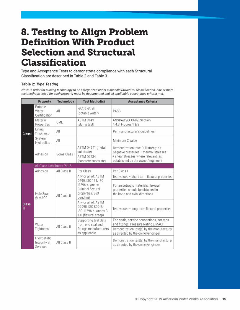
8. Testing to Align Problem Definition With Product Selection and Structural ClassificationType and Acceptance Tests to demonstrate compliance with each Structural Classification are described in Table 2 and Table 3.
Table 2: Type TestingNote: In order for a lining technology to be categorized under a specific Structural Classification, one or more test methods listed for each property must be documented and all applicable acceptance criteria met.
Property Technology Test Method(s) Acceptance Criteria
Class I
Potable Water Certification
All NSF/ANSI 61 (potable water) PASS
Material Properties CML ASTM C143
(slump test)ANSI/AWWA C602, Section 4.4.3, Figures 1 & 2
Lining Thickness All Per manufacturer’s guidelines
System Hydraulics All Minimum C value
Adhesion Some Class I
ASTM D4541 (metal substrate)
Demonstration test: Pull strength ≥ negative pressures + thermal stresses + shear stresses where relevant (as established by the owner/engineer)
ASTM D7234 (concrete substrate)
Class II
All Class I attributes PLUS:Adhesion All Class II Per Class I Per Class I
Hole Span @ MAOP All Class II
Any or all of: ASTM D790; ISO 178; ISO 11296-4, Annex B (initial flexural properties, 3-pt bending)
Test values = short-term flexural properties
For anisotropic materials, flexural properties should be obtained in the hoop and axial directions
Any or all of: ASTM D2990; ISO 899-2; ISO 11296-4, Annex C & D (flexural creep)
Test values = long-term flexural properties
Water Tightness All Class II
Supporting test data from end seal and fittings manufacturers, as applicable
End seals, service connections, hot taps and fittings: Pressure Rating ≥ MAOPDemonstration test(s) by the manufacturer as directed by the owner/engineer
Hydrostatic Integrity at Services
All Class II Demonstration test(s) by the manufacturer as directed by the owner/engineer
16 | © Copyright 2019 American Water Works Association
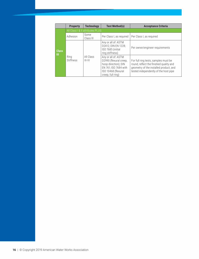
Property Technology Test Method(s) Acceptance Criteria
Class III
All Class I & II attributes PLUS:
Adhesion Some Class III Per Class I, as required Per Class I, as required
Ring Stiffness
All Class III-IV
Any or all of: ASTM D2412; DIN EN 1228; ISO 7685 (initial ring stiffness)
Per owner/engineer requirements
Any or all of: ASTM D2990 (flexural creep, hoop direction); DIN EN 761; ISO 7684 with ISO 10468 (flexural creep, full ring)
For full ring tests, samples must be round, reflect the finished quality and geometry of the installed product, and tested independently of the host pipe
© Copyright 2019 American Water Works Association | 17
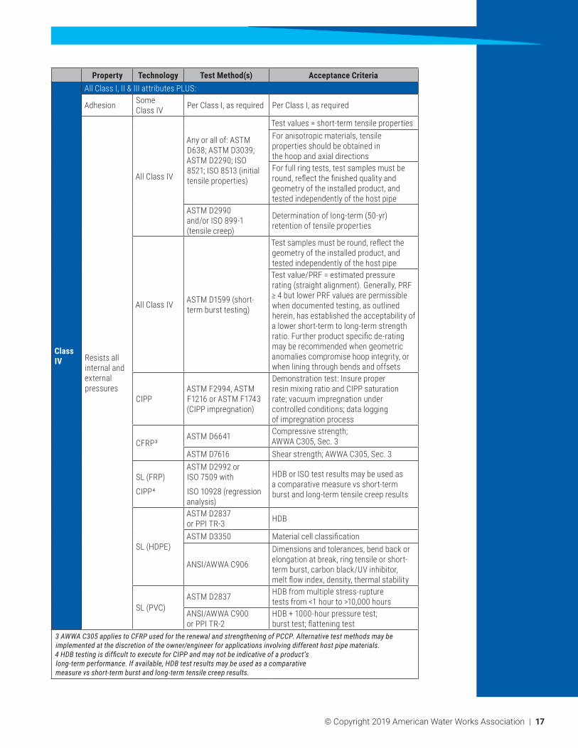
Property Technology Test Method(s) Acceptance Criteria
Class IV
All Class I, II & III attributes PLUS:
Adhesion Some Class IV Per Class I, as required Per Class I, as required
Resists all internal and external pressures
All Class IV
Any or all of: ASTM D638; ASTM D3039; ASTM D2290; ISO 8521; ISO 8513 (initial tensile properties)
Test values = short-term tensile propertiesFor anisotropic materials, tensile properties should be obtained in the hoop and axial directionsFor full ring tests, test samples must be round, reflect the finished quality and geometry of the installed product, and tested independently of the host pipe
ASTM D2990 and/or ISO 899-1 (tensile creep)
Determination of long-term (50-yr) retention of tensile properties
All Class IV ASTM D1599 (short-term burst testing)
Test samples must be round, reflect the geometry of the installed product, and tested independently of the host pipeTest value/PRF = estimated pressure rating (straight alignment). Generally, PRF ≥ 4 but lower PRF values are permissible when documented testing, as outlined herein, has established the acceptability of a lower short-term to long-term strength ratio. Further product specific de-rating may be recommended when geometric anomalies compromise hoop integrity, or when lining through bends and offsets
CIPPASTM F2994, ASTM F1216 or ASTM F1743 (CIPP impregnation)
Demonstration test: Insure proper resin mixing ratio and CIPP saturation rate; vacuum impregnation under controlled conditions; data logging of impregnation process
CFRP³ASTM D6641 Compressive strength;
AWWA C305, Sec. 3ASTM D7616 Shear strength; AWWA C305, Sec. 3
SL (FRP)
CIPP4
ASTM D2992 or ISO 7509 with
ISO 10928 (regression analysis)
HDB or ISO test results may be used as a comparative measure vs short-term burst and long-term tensile creep results
SL (HDPE)
ASTM D2837 or PPI TR-3 HDB
ASTM D3350 Material cell classification
ANSI/AWWA C906
Dimensions and tolerances, bend back or elongation at break, ring tensile or short-term burst, carbon black/UV inhibitor, melt flow index, density, thermal stability
SL (PVC)ASTM D2837 HDB from multiple stress-rupture
tests from <1 hour to >10,000 hoursANSI/AWWA C900 or PPI TR-2
HDB + 1000-hour pressure test; burst test; flattening test
3 AWWA C305 applies to CFRP used for the renewal and strengthening of PCCP. Alternative test methods may be implemented at the discretion of the owner/engineer for applications involving different host pipe materials.4 HDB testing is difficult to execute for CIPP and may not be indicative of a product’s long-term performance. If available, HDB test results may be used as a comparative measure vs short-term burst and long-term tensile creep results.

18 | © Copyright 2019 American Water Works Association
Table 3: Acceptance TestingNote: In order for a lining technology to be categorized under a specific Structural Classification, one or more test methods listed for each property must be documented and all applicable acceptance criteria met
Property Technology Test Method(s) Acceptance Criteria
Class I
Drinking Water System Components
– Health Effects
All Bacteriological testing AWWA C651
Material Properties CML, PL Compressive strength
CML: AWWA C602, Section 5.1.2PL: ASTM F3182, Section 6
Lining Thickness CML, PL Physical
measurementsCML: ANSI/AWWA C602, Table 1PL: ASTM F3182, Section 8.2
Adhesion Some Class I
Surface preparation and dryness
Surface preparation methods shall be confirmed by the owner/engineer before proceeding with the lining installation process.PL: ASTM F3182, Section 8.3
Visual and CCTV inspection
No visual leaks at ends or at servicesISO 11297-1:2013, Section 9.8PL: ASTM F3182, Section 7.9
ASTM D4541 (metal substrate)
Test values ≥ design valuePL: ASTM F3182, Section 8.3
ASTM D7234 (concrete substrate) Test values ≥ design value
Class II
All Class I attributes PLUS:Adhesion All Class II Per Class I Per Class I
Hole Span @ MAOP All Class II
ASTM D790 and/or ISO 11296-4, Annex B (initial flexural properties, axial direction)
Test values ≥ design submittal
If these criteria are not met, design compliance shall be verified using actual test values
Water Tightness All Class II
ASTM F1216, Section 8.3 (pressure test): 2 times MAOP or MAOP + 50 psi (3.4 bar), whichever is less,
Minimum 1-hour duration once system is stabilized; leakage allowance = 20 gal/inch diameter/mile/day (1.86 L/mm diameter/km/day)
or ISO 11297-4, Table 7 (pressure test): 1.5 times MAOP
15 minute test duration with no leakage per ISO 7432 or ISO 8533, as applicable
Class III
All Class I & II attributes PLUS:
Adhesion Some Class III Per Class I, as required
Per Class I, as requiredCIPP: ASTM F1216, Section 8.7; tight fit, full saturationCFRP: AWWA C305, Section 4.55
Ring Stiffness All Class III
ASTM D790 and/or ISO 11296-4, Annex B (initial flexural properties, hoop direction)
For anisotropic materials, flexural properties should be obtained in the hoop direction
Test values ≥ design submittal
© Copyright 2019 American Water Works Association | 19
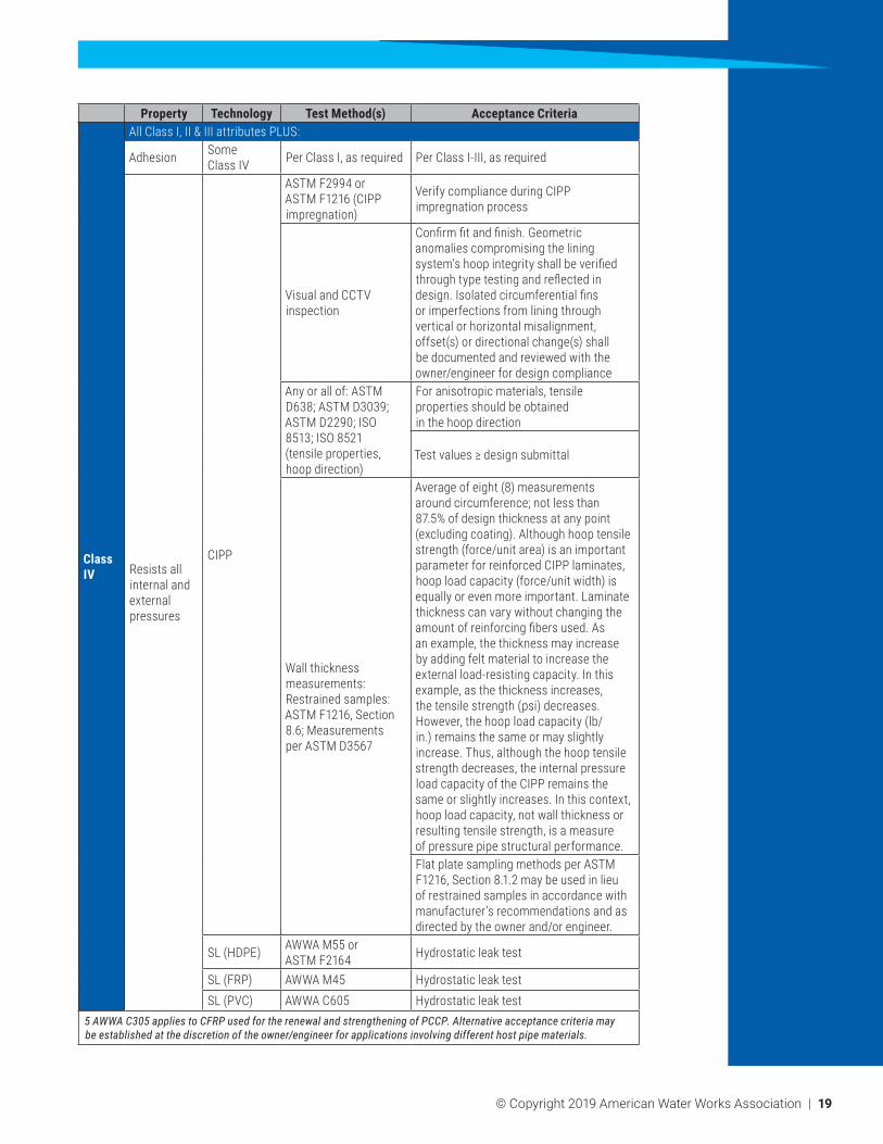
Property Technology Test Method(s) Acceptance Criteria
Class IV
All Class I, II & III attributes PLUS:
Adhesion Some Class IV Per Class I, as required Per Class I-III, as required
Resists all internal and external pressures
CIPP
ASTM F2994 or ASTM F1216 (CIPP impregnation)
Verify compliance during CIPP impregnation process
Visual and CCTV inspection
Confirm fit and finish. Geometric anomalies compromising the lining system’s hoop integrity shall be verified through type testing and reflected in design. Isolated circumferential fins or imperfections from lining through vertical or horizontal misalignment, offset(s) or directional change(s) shall be documented and reviewed with the owner/engineer for design compliance
Any or all of: ASTM D638; ASTM D3039; ASTM D2290; ISO 8513; ISO 8521 (tensile properties, hoop direction)
For anisotropic materials, tensile properties should be obtained in the hoop direction
Test values ≥ design submittal
Wall thickness measurements: Restrained samples: ASTM F1216, Section 8.6; Measurements per ASTM D3567
Average of eight (8) measurements around circumference; not less than 87.5% of design thickness at any point (excluding coating). Although hoop tensile strength (force/unit area) is an important parameter for reinforced CIPP laminates, hoop load capacity (force/unit width) is equally or even more important. Laminate thickness can vary without changing the amount of reinforcing fibers used. As an example, the thickness may increase by adding felt material to increase the external load-resisting capacity. In this example, as the thickness increases, the tensile strength (psi) decreases. However, the hoop load capacity (lb/in.) remains the same or may slightly increase. Thus, although the hoop tensile strength decreases, the internal pressure load capacity of the CIPP remains the same or slightly increases. In this context, hoop load capacity, not wall thickness or resulting tensile strength, is a measure of pressure pipe structural performance.Flat plate sampling methods per ASTM F1216, Section 8.1.2 may be used in lieu of restrained samples in accordance with manufacturer’s recommendations and as directed by the owner and/or engineer.
SL (HDPE) AWWA M55 or ASTM F2164 Hydrostatic leak test
SL (FRP) AWWA M45 Hydrostatic leak testSL (PVC) AWWA C605 Hydrostatic leak test
5 AWWA C305 applies to CFRP used for the renewal and strengthening of PCCP. Alternative acceptance criteria may be established at the discretion of the owner/engineer for applications involving different host pipe materials.
20 | © Copyright 2019 American Water Works Association
Appendix A—Design Considerations and Future Design Development (Non-mandatory; for Information and Discussion Purposes Only)
This Appendix is for informational purposes only and is intended to initiate and facilitate discussion on design issues associated with Class I through Class IV linings. The primary example used in Sections 3 and 4 is a CIPP CFL, which is for illustrative purposes only. CIPP is a complex lining material, which highlights many of the lining design issues that need to be addressed moving forward.
1. Typical Design Approaches Under Existing Standards
The basic design approaches that are currently used to resolve owner-defined problems are summarized in Table 4.

© Copyright 2019 American Water Works Association | 21
Table 4: Current Typical Design Approaches
Property Technology Design Procedure(s) Design Criteria
Class I
Potable Water Certification
All NSF/ANSI-61 Product certification (all system components)
Material Properties CML ANSI/AWWA
C602, Sec. 4.4 Mortar mix design
Lining Thickness CML ANSI/AWWA C602,
Sec. 4.4.5 Minimum lining thickness
Adhesion
All Project specific Surface preparation and dryness requirements to be submitted by the manufacturer and/or contractor
Adhesion strength ≥ negative pressures, thermal stresses, and shear stresses where relevant (Equations 1a and 1b)
PL ASTM F3182
System Hydraulics
All AWWA M45, Ch. 4 Minimum C value and pipe inside diameter required after lining to maintain or increase hydraulic capacity
CML AWWA C602PL AWWA C620
Class II
All Class I design requirements PLUS:Adhesion All Class II Per Class I Per Class I
Hole span @ MAOP All Class II
ASTM F1216, Equation X1.6 (as directed by X1.5)
All holes should be supported, or per manufacturer’s guidelinesIf Eq X1.5 can’t be satisfied, Eq X1.7 applies (reverts to Class IV design)
Water tightness All Class II See Table 3 See Table 3

22 | © Copyright 2019 American Water Works Association
Property Technology Design Procedure(s) Design Criteria
Class III
All Class I & II design requirements PLUS:
Adhesion Some Class III Per Class I, as required Per Class I, as required
Ring stiffness
All Class IIIASTM F1216, Equation X1.1 (vacuum and hydrostatic pressure)
For vacuum, use short-term flexural propertiesFor external hydrostatic pressures due to groundwater, short-term flexural properties, higher retention values or a lower design safety factor should be considered in design, unless the pressure pipe is expected to be out of service for an extended period or routinely operates under gravity conditions. External pressures should control lining design only when absolutely necessary.
SL (FRP)
AWWA M45, Equation 5-17 (in accordance with ASTM D2412) or AWWA M45, Equation 5-18
Per owner and/or engineer guidelines
AWWA M45, Eq. 5-24a
(wall buckling)
Allowable buckling pressure >
Total external pressureSL (PVC) AWWA M23 Per owner and/or engineer guidelinesSL (HDPE) AWWA M55 Per owner and/or engineer guidelines
CFRP6 AWWA C305, Section 2 Wall buckling (LRFD) – vacuum and hydrostatic pressure
Thermal effects
Some Class III
PPI Handbook of PE Pipe, Chapter 6, Equations 4-1 and 4-2
Lining systems that do not demonstrate reliable adhesion to the host pipe should be properly anchored or designed to accommodate axial movement due to temperature fluctuations
© Copyright 2019 American Water Works Association | 23
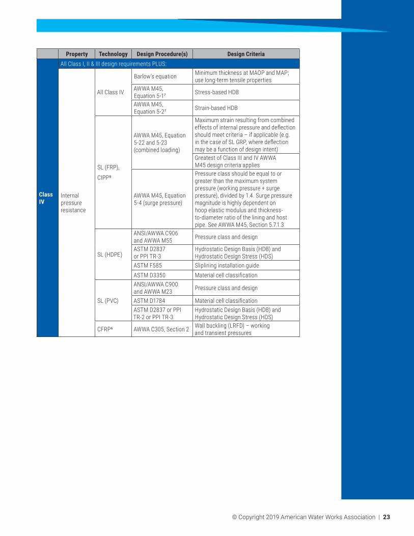
Property Technology Design Procedure(s) Design Criteria
Class IV
All Class I, II & III design requirements PLUS:
Internal pressure resistance
All Class IV
Barlow’s equation Minimum thickness at MAOP and MAP; use long-term tensile properties
AWWA M45, Equation 5-17 Stress-based HDB
AWWA M45, Equation 5-27 Strain-based HDB
SL (FRP),
CIPP8
AWWA M45, Equation 5-22 and 5-23 (combined loading)
Maximum strain resulting from combined effects of internal pressure and deflection should meet criteria – if applicable (e.g. in the case of SL GRP, where deflection may be a function of design intent)Greatest of Class III and IV AWWA M45 design criteria applies
AWWA M45, Equation 5-4 (surge pressure)
Pressure class should be equal to or greater than the maximum system pressure (working pressure + surge pressure), divided by 1.4. Surge pressure magnitude is highly dependent on hoop elastic modulus and thickness-to-diameter ratio of the lining and host pipe. See AWWA M45, Section 5.7.1.3
SL (HDPE)
ANSI/AWWA C906 and AWWA M55 Pressure class and design
ASTM D2837 or PPI TR-3
Hydrostatic Design Basis (HDB) and Hydrostatic Design Stress (HDS)
ASTM F585 Sliplining installation guideASTM D3350 Material cell classification
SL (PVC)
ANSI/AWWA C900 and AWWA M23 Pressure class and design
ASTM D1784 Material cell classificationASTM D2837 or PPI TR-2 or PPI TR-3
Hydrostatic Design Basis (HDB) and Hydrostatic Design Stress (HDS)
CFRP6 AWWA C305, Section 2 Wall buckling (LRFD) – working and transient pressures

24 | © Copyright 2019 American Water Works Association
Property Technology Design Procedure(s) Design Criteria
Class IV
External pressure resistance
All Class IV ASTM F1216, Section X1.2.2
Total external pressure on pipe (soil, hydrostatic and surface live load); applies when pipe is out of service for an extended period
All Class IV ASTM F1216, Equation X1.3
Applies when total external pressure > MAOP
CFRP6 AWWA C305, Section 2 LRFD – total external loads
Poisson’s effect
All Class IVPerformance Pipe
813-TN
Lining system must resist pullout forces due to Poisson’s effect. Maximum internal pressure should be used (greatest of MAP, MAOP and test pressure); see illustrative example, Equation (16)
CFRP6 AWWA C305, Section 2 Longitudinal strain from Poisson’s effect
Thrust restraint
All Class IV AWWA M45, Chapter 7
Applies to lining systems subjected to hydrostatic or hydrodynamic thrust; prescriptive design per AWWA M45, Chapter 7
CFRP6 AWWA C305, Section 2 Pressure-induced thrust force as calculated from AWWA Manual M9
6 AWWA C305 applies to CFRP utilized for the renewal and strengthening of PCCP. An alternative design approach may be implemented at the discretion of the owner/engineer for applications involving different host pipe materials.7 HDB testing is difficult to execute for CIPP and may not be indicative of a product’s long-term performance. HDB test results may be utilized as a comparative measure vs short-term burst and long-term tensile creep results.8 For CIPP, this design method may be utilized at the discretion of the owner/engineer when ASTM D2992 (HDB) test data is available

© Copyright 2019 American Water Works Association | 25
2. Limitations of Current Design Methods
While the current design approach may be appropriate for some lining systems, design methods in general are not well aligned with the products used and do not consider host pipe failure modes, which is particularly important for Class IV lining applications. Where the failure mode involves brittle fracture of the host pipe, active disbondment of the lining system is desired as opposed to adhesion. This is problematic for all CFL systems, which often employ reliable adhesion selectively or strive to achieve high degrees of mechanical inlock with the host pipe to maintain hydrostatic integrity.
Maintaining water tightness or hydrostatic integrity at existing services can be challenging when failure of the host pipe or pressure pipe system occurs through galvanic corrosion or other means. Demonstration tests may be coordinated by the manufacturer at the direction of the owner/engineer to simulate site conditions, confirm predicted performance and establish alternative repair measures when hydrostatic integrity is lost. This may include connecting a new service to the existing main by tapping into the lined pipe or directly to the lining system or replacing the service in-kind. Where a section of lined host pipe and/or associated appurtenances are removed and replaced, the lining system manufacturer shall provide guidance for proper reconnection to achieve water tightness or alternatively coordinate relevant demonstration tests with the owner/engineer to simulate installation conditions.
Additionally, testing for total system water tightness (i.e., inclusive of the main line, services, and appurtenances) can be problematic. Unknown variables associated with the existing piping network and site conditions can produce negative or misleading results and compromise system integrity. Facilitating proper setup and execution of a hydrostatic leakage test takes careful planning and introduces a high level of risk to the contractor and owner. This is especially a concern when the structural integrity of the existing piping network is in question and may not ensure its survival during hydrostatic pressure testing, which can lead to sudden, catastrophic failure.
Aside from adhesion, there are other problems associated with current CFL system design. Most CFL systems in practice use the design approach outlined in Appendix X1 of ASTM F1216 for structural design. The most common critical limit state in practice for Class IV linings is circumferential cracking under longitudinal forces, which is completely overlooked by ASTM F1216 Appendix X1. Thermal shrinkage, the Poisson effect, and pressurization forces at bends and other changes of alignment all contribute to longitudinal tensile and/or bending stresses. While a standard practice should be developed to address CFL design (as well as all other lining techniques where standard design practices are not currently developed), much of the design approach can be addressed through a reasonable application of proper engineering judgment to the products being employed and logical loads that the lining needs to resist based on design objectives. This is illustrated in the following sections based on the assumption of a CIPP lining being used to systematically elevate it from a Class I through Class IV level of Structural Classification.
26 | © Copyright 2019 American Water Works Association
3. Illustrative AWWA M28 Pressure Pipe Lining Design Methodology for a CIPP CFL Product
The reader should be advised that the design approach described herein is based on a potable water flow medium at room temperature, or 73°F (23°C). Elevated temperatures, chemical composition of the transporting fluid, or combination thereof may have an adverse effect on the performance of a lining system and should be taken into consideration in design. Contact the lining system manufacturer for additional guidance.
The product being vetted in this design example is a fiber-reinforced CIPP, an anisotropic lining material that by design is intended to bond to the host pipe.
The technical approach illustrated is a balance of recognizing the mechanical characteristics of the lining system, selecting design checks and models that are representative of the defects being resolved in the host pipe and then progressively walking through the Class I through Class IV design performance checks to ascertain an appropriate degree of structural and chemical resistance for the desired short- and long-term exposure conditions.
© Copyright 2019 American Water Works Association | 27
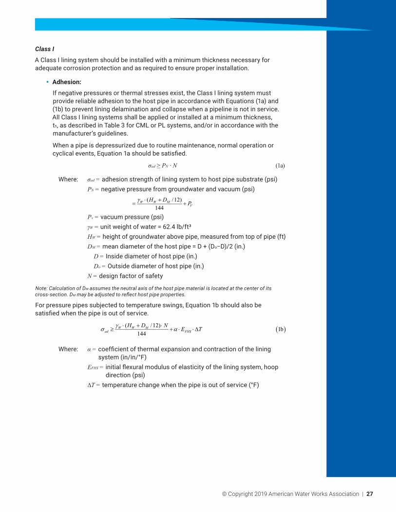
Class I
A Class I lining system should be installed with a minimum thickness necessary for adequate corrosion protection and as required to ensure proper installation.
y Adhesion:
If negative pressures or thermal stresses exist, the Class I lining system must provide reliable adhesion to the host pipe in accordance with Equations (1a) and (1b) to prevent lining delamination and collapse when a pipeline is not in service. All Class I lining systems shall be applied or installed at a minimum thickness, t1, as described in Table 3 for CML or PL systems, and/or in accordance with the manufacturer’s guidelines.
When a pipe is depressurized due to routine maintenance, normal operation or cyclical events, Equation 1a should be satisfied.
σad≥PN · N (1a)
Where: σad = adhesion strength of lining system to host pipe substrate (psi) PN = negative pressure from groundwater and vacuum (psi)
( /12)144
W W MV
H D Pγ ⋅ += +
Pv = vacuum pressure (psi) γW = unit weight of water = 62.4 lb/ft³ HW = height of groundwater above pipe, measured from top of pipe (ft) DM = mean diameter of the host pipe = D + (Do−D)/2 (in.) D = Inside diameter of host pipe (in.) Do = Outside diameter of host pipe (in.) N = design factor of safety
Note: Calculation of DM assumes the neutral axis of the host pipe material is located at the center of its cross-section. DM may be adjusted to reflect host pipe properties.
For pressure pipes subjected to temperature swings, Equation 1b should also be satisfied when the pipe is out of service.
Where: α= coefficient of thermal expansion and contraction of the lining system (in/in/°F)
EFHS = initial flexural modulus of elasticity of the lining system, hoop direction (psi)
∆T= temperature change when the pipe is out of service (°F)
( )( /12) 1b144
W W Mad FHS
H D N E Tγσ α⋅ + ⋅≥ + ⋅ ⋅∆

28 | © Copyright 2019 American Water Works Association
Class II
In addition to Class I design requirements, Class II lining systems shall be designed as follows:
y Hole Span:
Minimum thickness required to withstand internal pressure in spanning across any holes in the original pipe wall is calculated from Equation (2). This generally applies when lining through connections that are to be abandoned, or where future holes in the host pipe are anticipated due to external corrosion. Only holes with circular geometry are considered. For PL applications, all holes must be filled or otherwise supported (e.g., internal clamp repair) prior to lining application. For other lining technologies that may be used in Class II applications (e.g., CIPP, CFL, SL), holes > 1 inch (25mm) in diameter must be supported prior to lining unless otherwise recommended and supported by the lining system manufacturer.
Where: t2a = minimum lining thickness to span holes in the existing pipe wall (in.)
d = diameter of hole in the existing pipe wall (in.) σFAL = long-term flexural strength of the lining system, axial
direction (psi) PW = internal working pressure (psi) N = design factor of safety
Equation (2) assumes that the lining system is a flat plate fixed at the edge and subjected to transverse stress only. This applies only if Equation (3) is satisfied.
If Equation (3) is not satisfied, the lining system is in ring tension or hoop stress and must be designed as Class IV.
Class III
In addition to Class I and II design requirements, Class III lining systems shall be designed as follows. Note that for Class III linings, adhesion is not required to develop ring stiffness. However, it may be necessary to achieve a watertight seal (for example, where services are reinstated robotically). There are also situations where adhesion may not be desirable, such as on aboveground applications that experience broad temperature swings.
y External Buckling Resistance (Short-Term):
This applies to pressure pipelines that are depressurized periodically either due to routine maintenance or cyclical events. Under this scenario, loads are analyzed as instantaneous, dynamic loads. Equation (4a) applies to rigid host pipes.
2 12 2
(ASTM F1216, Eq. X1.6) (2)5.33 1
a
FAL
W
DtDd P N
σ= ⋅ + ⋅
( ) ( )12
21.83 ASTM F1216, Eq. X1.5 3atdD D
≤ ⋅
( )
( ) ( )3 1/3
2
ASTM F1216, Eq. X1.1 4a2 11
a
FHS
N
DtK E C
N Pυ
= ⋅ ⋅ ⋅ + − ⋅ ⋅

© Copyright 2019 American Water Works Association | 29
For flexible host pipes, live loads are also considered in Equation (4b), with an estimated 50% of the load transferred to the lining system. This is conservative since a Class III design assumes that the host pipe is structurally sound, and most aging pressure pipes are rigid and designed to carry load, not transfer it. Also, this approach assumes that the pipe incurs depressurization and surface live loads simultaneously, which is a worst-case scenario.
Where: t3a = minimum lining thickness to resist short-term buckling pressures (in.)
K = enhancement factor of the soil and existing pipe adjacent to the new pipe; a minimum value of 7.0 is recommended where there is full support of the existing pipe (dimensionless)
C = ovality reduction factor (dimensionless) = [ ]
3
21 /1001 /100
− + q = ovality of host pipe (%)*
ν= Poisson’s ratio of the lining system (dimensionless) Ws = surface live load at pipe burial depth (psi)
*Ovality is generally not a consideration for pressure pipe designs. However, when a pipe taken out of service is subjected to external pressures, ovality may be relevant. In absence of physical measurements, reasonable assumptions of ovality should be made based on host pipe material properties and in situ conditions. For example, ovality may never be observed on a rigid host pipe over the course of its design life, while a flexible pressure pipe may or may not ovalize (or deflect) when taken out of service.
y External Buckling Resistance (Long-Term):
This applies to pressure pipelines that are out of service for extended periods of time. Examples may include pipelines undergoing maintenance or systems with built-in redundancy.
Where: t3b = minimum lining thickness to resist long-term buckling pressures (in.)
EFHL = long-term flexural modulus of elasticity of the lining system, hoop direction (psi)
y Thermal Effects:
When reliable adhesion to the host pipe is desired, lining through existing expansion joints is not recommended, as this can result in sudden and catastrophic failure of the lining system.
Class III lining systems demonstrating reliable adhesion to the host pipe should use Equation (1b) as a design check for thermal stresses.
( )
( ) ( )3 1/3
2
ASTM F1216, Eq. X1.1, modified 4b2 1
1 ( / 2)
a
FHS
N s
DtK E CN P Wυ
= ⋅ ⋅ ⋅ + − ⋅ ⋅ +
( )
( ) ( )3 1/3
2
ASTM F1216, Eq. X1.1 52 11
b
FHL
N
DtK E C
N Pυ
= ⋅ ⋅ ⋅ + − ⋅ ⋅
30 | © Copyright 2019 American Water Works Association
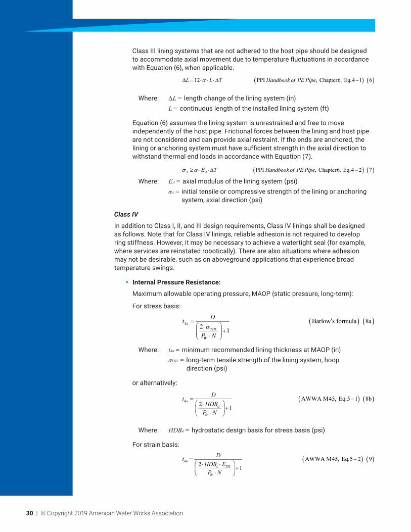
Class III lining systems that are not adhered to the host pipe should be designed to accommodate axial movement due to temperature fluctuations in accordance with Equation (6), when applicable.
Where: ∆L= length change of the lining system (in) L = continuous length of the installed lining system (ft)
Equation (6) assumes the lining system is unrestrained and free to move independently of the host pipe. Frictional forces between the lining and host pipe are not considered and can provide axial restraint. If the ends are anchored, the lining or anchoring system must have sufficient strength in the axial direction to withstand thermal end loads in accordance with Equation (7).
Where: EA = axial modulus of the lining system (psi) σA = initial tensile or compressive strength of the lining or anchoring
system, axial direction (psi)
Class IV
In addition to Class I, II, and III design requirements, Class IV linings shall be designed as follows. Note that for Class IV linings, reliable adhesion is not required to develop ring stiffness. However, it may be necessary to achieve a watertight seal (for example, where services are reinstated robotically). There are also situations where adhesion may not be desirable, such as on aboveground applications that experience broad temperature swings.
y Internal Pressure Resistance:
Maximum allowable operating pressure, MAOP (static pressure, long-term):
For stress basis:
Where: t4a = minimum recommended lining thickness at MAOP (in) σTHL = long-term tensile strength of the lining system, hoop
direction (psi)
or alternatively:
Where: HDBσ = hydrostatic design basis for stress basis (psi)
For strain basis:
( ) ( )12 PPI , Chapter 6, Eq. 4 1 6L L T Handbook of PE Pipeα∆ = ⋅ ⋅ ⋅∆ −
( ) ( ) PPI , Chapter 6, Eq. 4 2 7A AE T Handbook of PE Pipeσ α≥ ⋅ ⋅∆ −
( ) ( )4 Barlow s formula 8a2 1
aTHL
W
Dt
P Nσ
= ⋅
+ ⋅
′
( ) ( )4 AWWA M45, Eq. 5 1 8b2 1
a
W
DtHDBP N
σ
= − ⋅
+ ⋅
( ) ( )4 AWWA M45, Eq. 5 2 92 1
bTH
W
DtHDB EP N
∈
= − ⋅ ⋅
+ ⋅
© Copyright 2019 American Water Works Association | 31
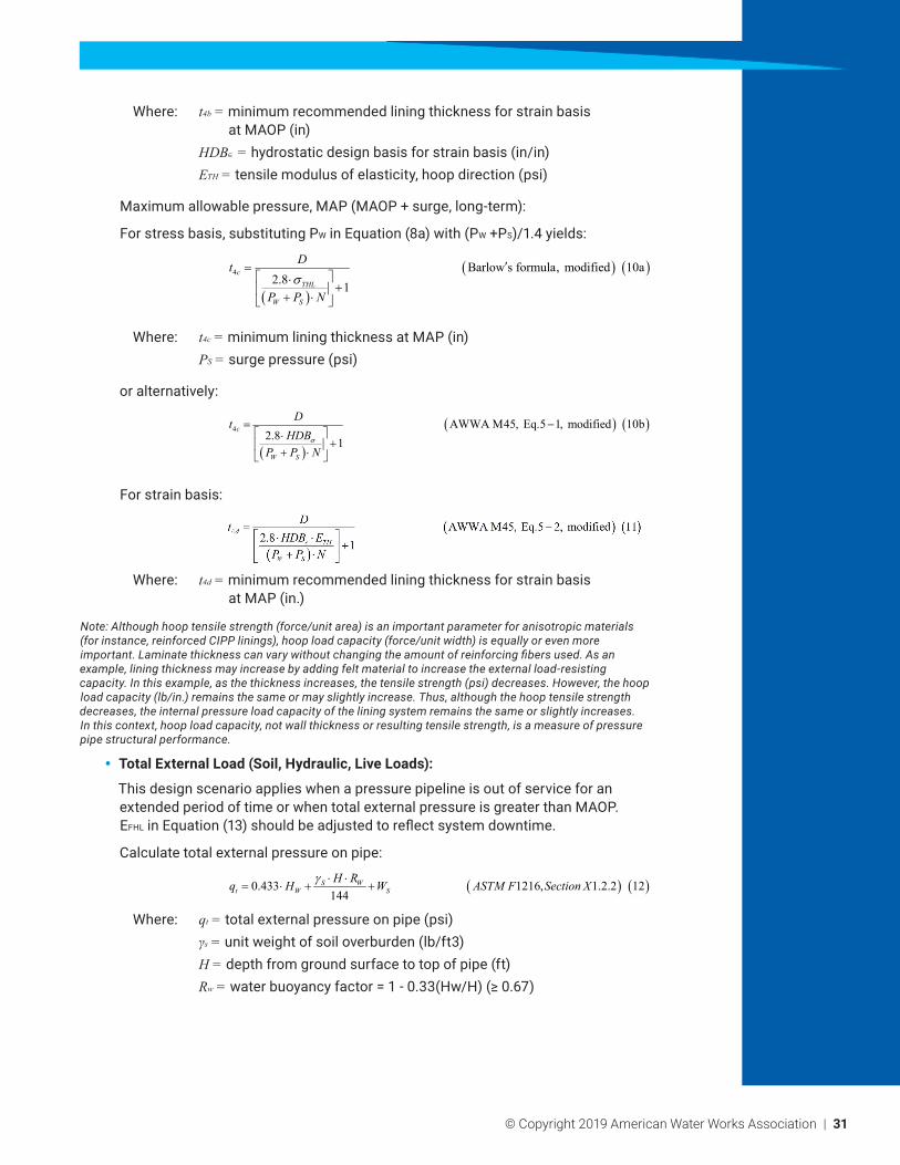
Where: t4b = minimum recommended lining thickness for strain basis at MAOP (in)
HDB∈ = hydrostatic design basis for strain basis (in/in) ETH = tensile modulus of elasticity, hoop direction (psi)
Maximum allowable pressure, MAP (MAOP + surge, long-term):
For stress basis, substituting PW in Equation (8a) with (PW +PS)/1.4 yields:
Where: t4c = minimum lining thickness at MAP (in) PS = surge pressure (psi)
or alternatively:
For strain basis:
Where: t4d = minimum recommended lining thickness for strain basis at MAP (in.)
Note: Although hoop tensile strength (force/unit area) is an important parameter for anisotropic materials (for instance, reinforced CIPP linings), hoop load capacity (force/unit width) is equally or even more important. Laminate thickness can vary without changing the amount of reinforcing fibers used. As an example, lining thickness may increase by adding felt material to increase the external load-resisting capacity. In this example, as the thickness increases, the tensile strength (psi) decreases. However, the hoop load capacity (lb/in.) remains the same or may slightly increase. Thus, although the hoop tensile strength decreases, the internal pressure load capacity of the lining system remains the same or slightly increases. In this context, hoop load capacity, not wall thickness or resulting tensile strength, is a measure of pressure pipe structural performance.
y Total External Load (Soil, Hydraulic, Live Loads):
This design scenario applies when a pressure pipeline is out of service for an extended period of time or when total external pressure is greater than MAOP. EFHL in Equation (13) should be adjusted to reflect system downtime.
Calculate total external pressure on pipe:
Where: qt = total external pressure on pipe (psi) γs = unit weight of soil overburden (lb/ft3) H = depth from ground surface to top of pipe (ft) Rw = water buoyancy factor = 1 - 0.33(Hw/H) (≥ 0.67)
( )
( ) ( )4 Barlow s formula, modified 10a2.8 1
cTHL
W S
Dt
P P Nσ
= ⋅
+ + ⋅
′
( )
( ) ( )4 AWWA M45, Eq. 5 1, modified 10b2.8 1
c
W S
DtHDB
P P Nσ
= − ⋅
+ + ⋅
( ) ( )0.433 1216, 1.2.2 12144
S Wt W S
H Rq H W ASTM F Section Xγ ⋅ ⋅= ⋅ + +
32 | © Copyright 2019 American Water Works Association
If qt > PW, use Equation (13) as an additional design check. If qt ≤ PW, internal pressure controls design.
Where: Msn = constrained soil modulus (psi) B’ = coefficient of elastic support = 1/(1+4e-0.065H)
y Check Working Pressure (MAOP):
The Class IV lining system should also satisfy the following criteria:
For host pipe in straight alignment:
Where: PB = short-term burst pressure of lining system per ASTM D1599 (psi) PRF= pressure rating factor (dimensionless)
PRF is material dependent but is generally ≥ 4. Further de-rating (i.e., a higher PRF) may be necessary when lining through bends. Additional guidance on the appropriate PRF used should be obtained from the lining system manufacturer.
y Check Surge Pressure (MAP):
For host pipe in straight alignment:
y Poisson’s Effect:
Poisson’s effect is a natural response to applied stress that occurs with all materials. As a pipe is pressurized, it elongates (stretches) circumferentially and contracts (shortens) lengthwise. The higher the internal pressure, the greater Poisson’s effect. Equation (16) estimates pullout forces from Poisson’s effect on a Class IV lining system. The maximum internal pressure should be used in this calculation, or the greatest of MAOP, MAP, and test pressure. Appropriate measures should be taken to ensure the lining system is properly restrained.
Where: FP = pullout force from Poisson’s effect (lbs) σP = maximum hoop stress ( )1
2PP DR⋅ −
= (psi) PP = maximum internal pressure; greatest of MAOP, MAP, and test
pressure (psi) DR = dimension ratio of lining system = D/t4
t4 = minimum Class IV wall thickness as determined by design checks (in.)
y Thrust Restraints:
Lining systems subjected to hydrostatic or hydrodynamic thrust should be designed in accordance with AWWA Manual of Water Supply Practices M45, Chapter 7, latest edition.
( ) ( ) ( )1/32 3
4
12 ASTM F1216, Equation X1.3 13
32t
eW sn FHL
q N Dt
R B M E C
⋅ ⋅ ⋅=
⋅ ⋅ ⋅′ ⋅ ⋅
( ) 14Bw
PPPRF
≤
( ) 151.4
w s BP P PPRF
+≤
( ) ( )22
1 1 from Performance Pipe 813 TN 16P PF DDR DR
σ υ π = ⋅ ⋅ ⋅ ⋅ − −
© Copyright 2019 American Water Works Association | 33
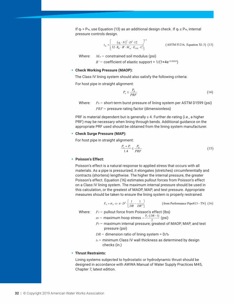
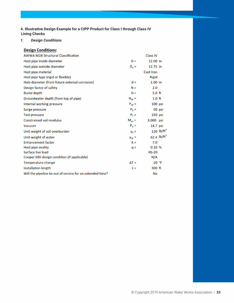
4. Illustrative Design Example for a CIPP Product for Class I through Class IV Lining Checks
1. Design Conditions

34 | © Copyright 2019 American Water Works Association
2. Lining Properties (from the Manufacturer)
Class I and Class II Checks – Adhesion and Hole Spanning
© Copyright 2019 American Water Works Association | 35
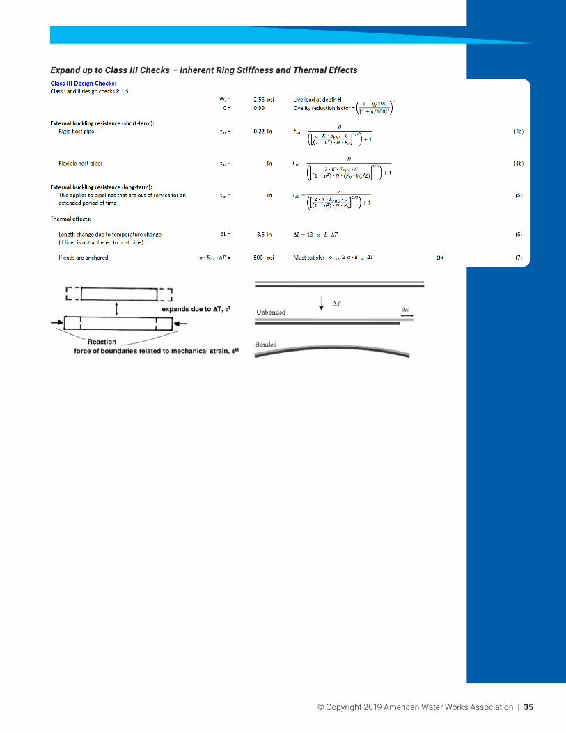
Expand up to Class III Checks – Inherent Ring Stiffness and Thermal Effects

36 | © Copyright 2019 American Water Works Association
Class IV Design Checks – Phase 1 Sustained Pressure
Class IV Design Checks – Phase 2 Short-Term Overpressure
Class IV Design Checks – Phase 3 External Loads
Consider:
1 . What buckling model to use:
a. Modified Luscher Buckling? (full overburden—no host pipe)
b. Timoshenko or Glock Models for hydrostatic stress only? (Host pipe has inherent ring strength over time)
2 . Duration of external load: How long will your pipe really be out of service? 1,000 hr, 1 year or a 50-year modulus

© Copyright 2019 American Water Works Association | 37
Class IV Design Checks – Phase 4 Alignment Modifications
Class IV Design Checks – Phase 5 Poisson’s Effect

38 | © Copyright 2019 American Water Works Association
Class IV Design Checks – Phase 6 Longitudinal Loads – Thrust
Is the original thrust restraint adequate?
y If no, need to accommodate axial forces
y If yes, no check necessary
y In this case, the owner’s problem statement indicated that original thrust restraint was fine
© Copyright 2019 American Water Works Association | 39
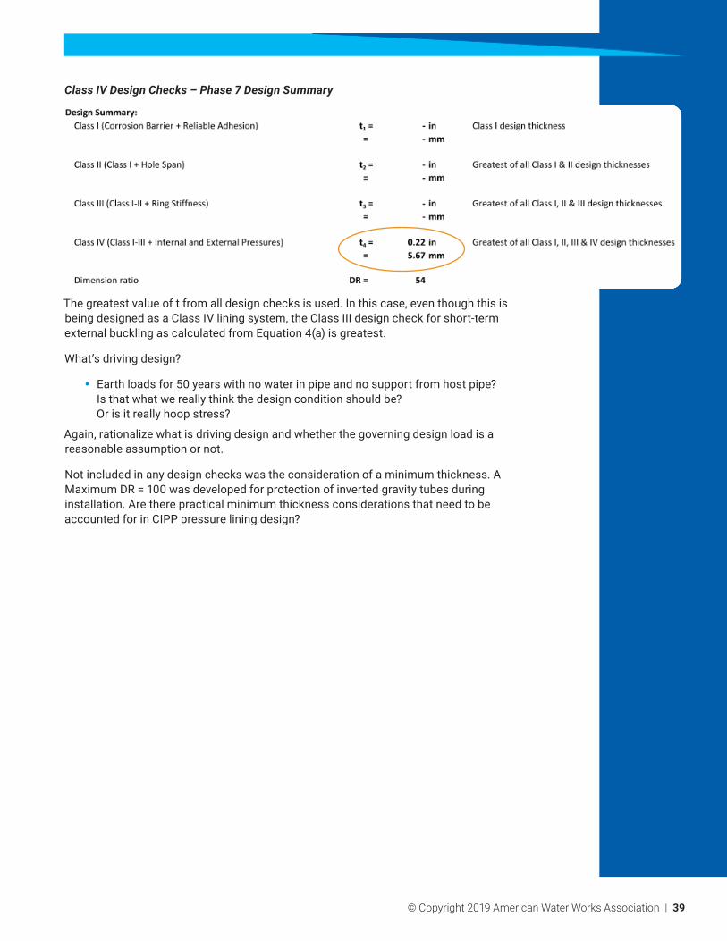
Class IV Design Checks – Phase 7 Design Summary
The greatest value of t from all design checks is used. In this case, even though this is being designed as a Class IV lining system, the Class III design check for short-term external buckling as calculated from Equation 4(a) is greatest.
What’s driving design?
y Earth loads for 50 years with no water in pipe and no support from host pipe? Is that what we really think the design condition should be? Or is it really hoop stress?
Again, rationalize what is driving design and whether the governing design load is a reasonable assumption or not.
Not included in any design checks was the consideration of a minimum thickness. A Maximum DR = 100 was developed for protection of inverted gravity tubes during installation. Are there practical minimum thickness considerations that need to be accounted for in CIPP pressure lining design?

Ideal crop marks