structural and vibrational response analysis of h.p...
TRANSCRIPT

http://www.iaeme.com/IJMET/index.asp 306 [email protected]
International Journal of Mechanical Engineering and Technology (IJMET)
Volume 7, Issue 3, May–June 2016, pp.306–319, Article ID: IJMET_07_03_028
Available online at
http://www.iaeme.com/IJMET/issues.asp?JType=IJMET&VType=7&IType=3
Journal Impact Factor (2016): 9.2286 (Calculated by GISI) www.jifactor.com
ISSN Print: 0976-6340 and ISSN Online: 0976-6359
© IAEME Publication
STRUCTURAL AND VIBRATIONAL
RESPONSE ANALYSIS OF H.P. BLADED
DISC ASSEMBLY
Bharath Bhaskar, Anand. S. N. and Dr.T.Krishna Rao
School of Mechanical Engineering
Reva University, Bangalore, Karnataka, India
ABSTRACT
In this article, an effort has been made to deal with structural behavior of
the Steam turbine HP blade and disc assembly rotating at 100% (6000 rpm)
optimum speed and 120% (7200rpm) over speed conditions which in turn
create large amount of centrifugal force. This is the dominating force in steam
turbine blade assembly which is the cause for all its behavior. Vibrational
analysis of this HP blade and disc assembly is also carried out using FEA
methods to determine and predict the fatigue life of the blade and disc. The
Structural analysis is carried out on the HP blade and disc to understand the
Structural behaviors which comes on them in order to find out the factor of
safety of the HP blade and disc assembly due to high angular velocity. The
Vibrational analysis is then carried out on HP steam turbine blade and disc
assembly to find out the Frequencies acting on them for first 5 modes and to
predict the safety of the blade and disc with the help of Campbell Diagram.
Finally, the fatigue life analysis is carried out on the HP Blade and disc
assembly with the help of S-N curve diagram for estimation of the fatigue life
of the HP blade as well as the disc for satisfactory design of any steam turbine
blade and disc assembly.
Cite this Article: Bharath Bhaskar, Anand. S. N. and Dr.T.Krishna Rao,
Structural and Vibrational Response Analysis of H.P. Bladed Disc Assembly.
International Journal of Mechanical Engineering and Technology, 7(3), 2016,
pp. 306–319.
http://www.iaeme.com/currentissue.asp?JType=IJMET&VType=7&IType=3
1 INTRODUCTION
In modern day world, Application of steam turbine as a device that is used to
transform the thermal energy of the steam into mechanical energy by turning the rotor
blades. Steam turbines are used as prime movers in all thermal and nuclear power
plants to produce electricity, large ships, pumps and fans at petrochemical plants. The
majority of steam turbines have two essential components or sets of such components.
Structural and Vibrational Response Analysis of H.P. Bladed Disc Assembly
http://www.iaeme.com/IJMET/index.asp 307 [email protected]
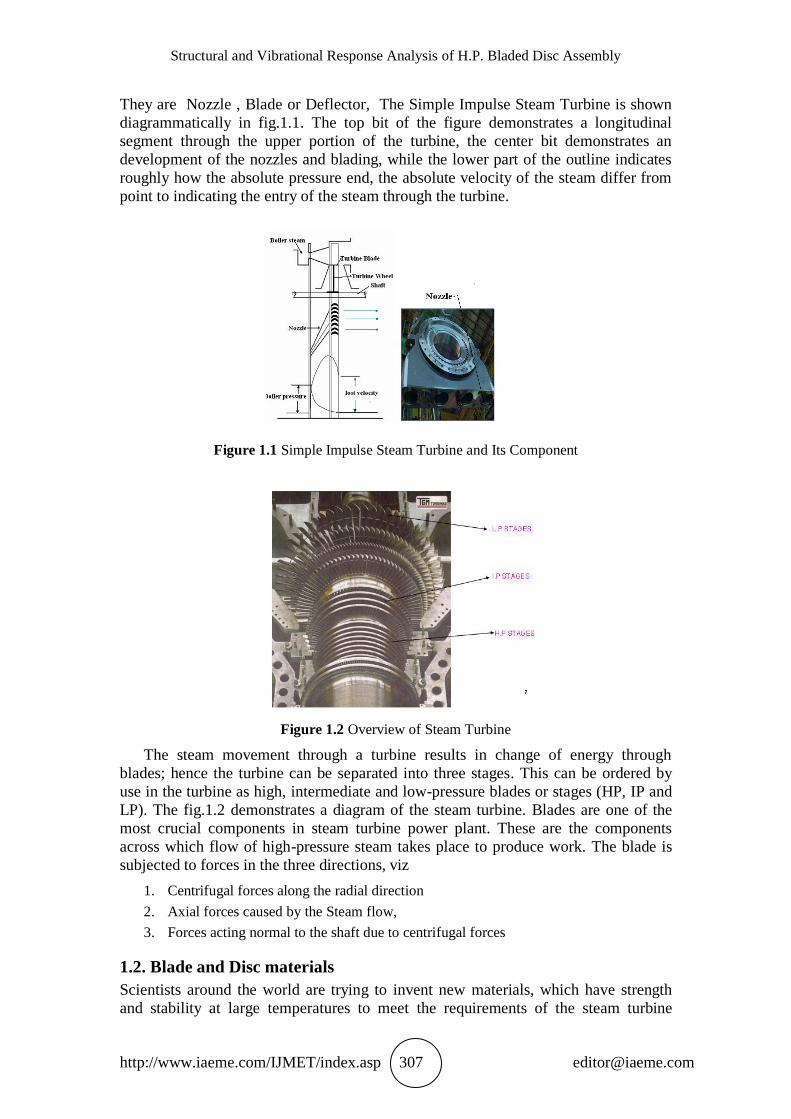
They are Nozzle , Blade or Deflector, The Simple Impulse Steam Turbine is shown
diagrammatically in fig.1.1. The top bit of the figure demonstrates a longitudinal
segment through the upper portion of the turbine, the center bit demonstrates an
development of the nozzles and blading, while the lower part of the outline indicates
roughly how the absolute pressure end, the absolute velocity of the steam differ from
point to indicating the entry of the steam through the turbine.
Figure 1.1 Simple Impulse Steam Turbine and Its Component
Figure 1.2 Overview of Steam Turbine
The steam movement through a turbine results in change of energy through
blades; hence the turbine can be separated into three stages. This can be ordered by
use in the turbine as high, intermediate and low-pressure blades or stages (HP, IP and
LP). The fig.1.2 demonstrates a diagram of the steam turbine. Blades are one of the
most crucial components in steam turbine power plant. These are the components
across which flow of high-pressure steam takes place to produce work. The blade is
subjected to forces in the three directions, viz
1. Centrifugal forces along the radial direction
2. Axial forces caused by the Steam flow,
3. Forces acting normal to the shaft due to centrifugal forces
1.2. Blade and Disc materials
Scientists around the world are trying to invent new materials, which have strength
and stability at large temperatures to meet the requirements of the steam turbine

Bharath Bhaskar, Anand. S. N. and Dr.T.Krishna Rao
http://www.iaeme.com/IJMET/index.asp 308 [email protected]
designers. Various alloy compositions are developed which have a good stability to
withstand the thermal stresses, these alloys have been modified to give good erosion-
corrosion characteristics to the blade. Among these various materials, the few which
have found to be apt for use in blades are steels, titanium alloys and nickel-based
alloys. All the three types of alloys, which are mainly used, have variations in the
proportion of chromium and aluminum to improve the strength and corrosion at high
temperature. Nickel alloys have also been developed extensively and are currently
being used for steam turbine engine. These alloys have superior strength and
oxidation resistance even though nickel by itself has poor oxidation resistance. This
weakness is overcome by alloying with chromium. In alloys, chromium is generally
20 – 30 % and forms chromium oxide (Cr2O3) protective layer and chromium carbide.
Other elements generally added are aluminum, titanium and niobium to improve the
strength at high temperature. Current alloys also use cobalt, hafnium, boron,
zirconium, molybdenum etc.
Blades are mounted on a disc in series, hence care must be taken in design and
material selection to avoid the catastrophic failure of the disc, based on yield and
ultimate strength at different temperatures, resistance to creep relaxation and good
fracture toughness at ambient temperature conditions and operating temperatures.
Steel based alloy performed these characteristics and lower levels of sulfur and
phosphorous results in the attainment of a high strength, tempered, lower bainite
structures having high toughness. In the present work chromium vanadium steel alloy
with different proportion is used for Disc. The fig.1.3 shows a conventional bladed
disc assembly used in turbines.
1.4. MATHEMATICAL MODELLING
1.4.1. Stresses induced Rotating Disk:
The Mathematical modeling of disk wheel rotating at high speed in steam turbines are
considered. The large stresses are due to centrifugal forces of the rotating disk which
acts radially outwards.
Since disk is symmetric, Let the centrifugal force in tangential direction is
Rr= r2 , Rθ = 0 (1)
We know that, the differential equation of motion for rotating disk at equilibrium is
0)(1
rr
r Rrr
(2)
Where r = Radial stress = Tangential Stress
By solving the above two equation,
22)( rr
r rr
(3)
Airy’s stress function is r
r

Structural and Vibrational Response Analysis of H.P. Bladed Disc Assembly
http://www.iaeme.com/IJMET/index.asp 309 [email protected]
After simplification of eq.3, we get 22r
r
The compatibility equation for rotational disk is
)(1
r
rr (4)
After substituting the Generalized Hook’s law, the relations for the plane stress
condtion in the above equation,
)(1
rrE
)(1
rE
r = Radial Strain, = Tangential strain
By solving the above two equation,
Radial strain
221
rrrE
r
Tangential strain
rr
rE
221
Substituting above two equations in compatibility equation eqn. (4) and
simplifying it,
We get
)3(),(1 22
r
dr
rd
rdr
d
Upon integrating the above equation
)3(
),(1 22
rdr
rd
rdr
d
The Airy’s stress function
r
Cr
Cr 2132
2)3(
8
1
Where C1 and C2 are constant of integration and can be found by initial
conditions.
Substitute the Airy’s stress function in the above equation, we get
The Radial stress is 2
2122
2)3(
8
1
r
CCrr (5)
The Tangential Stress is 2
2122
2)31(
8
1
r
CCr (6)
1.4.2. Hollow Disk
Consider the hallow disk with central inner hole of inner radius ‘a’ and outer radius
‘b’.
By initial boundary condition to eqn. (5) and eqn. (6) i.e.

Bharath Bhaskar, Anand. S. N. and Dr.T.Krishna Rao
http://www.iaeme.com/IJMET/index.asp 310 [email protected]
At r = a, r = 0, and
r = b, r = 0
We can find the constant of integration i.e. C1 and C2.
The Radial Stress induced is
2
2
22222 )()3(
8
1r
r
babar
The Tangential Stress induced is
2
2
22222
3
31)()3(
8
1r
r
baba
the maximum radial stress ( r ) max and maximum ( ) max and minimum ( ) min
tangential stress for the rotating disk due to centrifugal load, Differentiating the above
equation with respects to radius ‘r’
The maximum radial stress at r = ab is
( r ) max= )()3(
8
1 222 ba
Induced Maximum tangential stress at r = a,
( ) max
2
2
22
3
11)3(
4
1
b
ab
Minimum tangential stress at r = b i.e.
( ) min is ( ) min
2
2
22
3
11)3(
4
1
a
ba
2. NUMERICAL METHODOLOGIES:
2.1 Geometric Modeling of Blade and Disc Assembly
For the present analysis the blades of the HP stage row were considered. Generally
the HP stage blades are tip shrouded, because they have to resist huge bending forces
produced by the steam loads. The geometry of the blade disc sector is modeled using
commercially available modeling software CatiaV5. A minimum of 30 co-ordinate
points at each section are selected from the list to represent the geometry as accurately
as possible. These coordinates are used to generate the aerofoil surface. T-root of the
blade is reproduced with best possible fillet to avoid sharp corner of the blade for
analysis. The geometric model of HP stage bladed disc is as shown in fig.2.1.
Blade Dimention:
Blade height= 26.2mm
Thickness of leading edge = 3 to 5mm
Thickness of trailing edge= 0.19 to 0.2mm
Number of blades = 60
Sector angle = 60
Mean diameter = 250 to 350mm

Structural and Vibrational Response Analysis of H.P. Bladed Disc Assembly
http://www.iaeme.com/IJMET/index.asp 311 [email protected]
Figure 2.1 Geometric Modeling of the Blade Disc sector
2.2. F.E Model of HP Blade
The FE model of the HP stage blade disc sector is discretized by the choosing solid
brick element with 8 nodes. In order to achieve the convergence the aspect ratio of
blade fillet and disc fillet portions are considered less than 5%, whereas aspect ratio in
the disc is considered less than 10%. To generate the contact between blade and disc,
contact 173 element for the blade contact region and target 170 element for the disc
region is considered in the present work.
For the present analysis 40757 nodes and 10943 elements are generated to achieve
the convergence. The blade and disc at T-root are discretized with such a margin that
the blade and disc considered are of similar number of element division. In order to
achieve continuity, fine mesh is considered in this zone. The FE model of geometry is
as shown in fig.2.2, fig.2.3 and fig.2.4.
Fig.2.2 FE Model of Blade Fig.2.3 FE Model of Disc Fig.2.4 FE Model
of Blade Disc Sector
2.3 Boundary Conditions
For the purpose of analysis a sector of the blade disc is considered. The considered
model as sector angle of 60 and the model is cyclic-symmetric in nature. The hoop
displacement at low edge and high edge of the blade and disc are arrested. In order to
avoid the rigid body motion one of the node is arrested in the axial direction as shown
in the fig.5.8. Contact 173 and Target 170 elements are used to generate the blade and
disc contact. In the contact zones of blade and disc, it is assumed frictionless support

Bharath Bhaskar, Anand. S. N. and Dr.T.Krishna Rao
http://www.iaeme.com/IJMET/index.asp 312 [email protected]
i.e., normal contact with axial motion is restricted and sliding motion is possible with
other directions. In the analyses rotational speed of 6000 rpm and 7200 rpm is
considered for operating and over speed conditions respectively
Figure 2.5 Boundary Conditions
2.4. Material Properties
The Chromium-Vanadium alloy materials at room temperature 270c have been
considered and shown in the Table.
Table 2.1 Mechanical Properties
Mechanical Properties Blade
(Cr 13MoV59)
Disc
(28CrMoV55)
Young’s Modulus (E) 2.18e5MPa 2.11e5 MPa
Density(ρ) 7750 Kg/m3 7800 Kg/m
3
Poison’s ratio(ν) 0.33 0.3
Yield strength(σy) 540Mpa 590Mpa
3. RESULTS AND DISCUSSIONS
3.1. HP bladed disc
In present work, the following observations were made pertaining to the HP bladed
disc sector of steam turbine at 6000rpm with appropriate boundary conditions as
explained earlier with over speed conditions as per API standards.
The results of the same classified under two group one for structural analysis and
other pertaining to coupled frequencies. Finally some observations are also made for
low cycle fatigue life and structural safety margins. The output of the structural
analysis is done as following ways.
The HP blade is categorized from structural point of view into three zones, hub,
tip and mean. The tip is considered to be most crucial because the rubbing of blade
against the casing during operating conditions. The average stress in aerofoil is very
important from blade bending stress point of view which cause due to both self-
weight of blade and steam loads. The last part of blade disc assembly is the hub, the
blade and disc interface and which happens to be the most critical zone of assembly.

Structural and Vibrational Response Analysis of H.P. Bladed Disc Assembly
http://www.iaeme.com/IJMET/index.asp 313 [email protected]
3.1.1. Displacement Analysis
From the analysis it is found that the radial growth of blade at 100% speed varied
from 0mm to 0.18568mm and over speed conditions the displacements were 0mm to
0.20942mm indicating clearly the absence of allowing radial growth of blade for tip
rubbing conditions. The fig.3.1 shows the radial growth of blade at 6000rpm
Figure 3.1 Radial Growth of Blade at 6000rpm
3.1.2. Stress Analysis
3.1.2.1 Stresses in the blade
From the analysis it is found that the von-mises stress in the blade varied from
0.8338MPa at the tip to maximum 581.93 MPa at blade root is as shown in fig.3.2.
The stresses in the tang region is appears to be 300 to 350MPa. The principle stresses
which are highly tensile in nature play a vital role in deciding Low cycle fatigue life
of the blade which is found to be 571.3MPa at the blade root. The blade neck which
resist the centrifugal pull at operating condition as developed an average equivalent
von-mises stress equal to 101.04 MPa at 100% speed is as shown fig.7.5 and
146.07MPa at 120% speed for over speed condition, since stresses developed were
with in the design limit. The blade stresses at the neck region is 0.08338Mpa to
581.93Mpa were also considered as safe from gross yielding point of view. The
maximum average centrifugal stress developed in the aerofoil is equal to 101.44Mpa.
The yield stress of the blade at room temperature is 590MPa. Hence the stresses
developed are well within the yield stress; hence the blade is very much safe from
failure.

Bharath Bhaskar, Anand. S. N. and Dr.T.Krishna Rao
http://www.iaeme.com/IJMET/index.asp 314 [email protected]
Fig.3.2 Avg.Von-Mises Stress in the Blade at 6000rpm Fig.3.3 Avg. Von-Mises
Stress in the disk at 6000rpm
3.1.2.2. Stresses developed in the steam turbine disc
The stresses developed in the disc is varies from 27.218 to 596.05MPa.The peak
stress developed in the disc at blade disc interface is 596.05MPa is as shown in
fig.3.6.The stress developed at fillet region of bladed disc interface is maximum
because the stress concentration will be more at this region . Hence the stress
developed is safe from net yielding point of view. The average sectional stress at less
cross section of the disc which has huge centrifugal force happens to be 125.54 MPa
at 100% speed is as shown in fig.3.4 and 180.77MPa at 120% speed. The yield stress
of the disc considered for analyses is 540MPa. Hence the stress developed is very
much safe from design limits. Fig.3.6 shows the stresses developed in blade disc
sector, the stress developed is maximum at blade disc interface that is 596.05MPa.
The table: 3.1 shows the average vonmises stress developed and factor of safety in the
blade and disc.
.

Structural and Vibrational Response Analysis of H.P. Bladed Disc Assembly
http://www.iaeme.com/IJMET/index.asp 315 [email protected]
Figure 3.4 Stresses Distribution in the Disc at 6000rpm
Figure 3.5 Average Von-Mises Stress Distribution at Minimum Cross Section of Disc
Figure 3.6 Stress in Blade Disc Sector at 6000rpm
Bharath Bhaskar, Anand. S. N. and Dr.T.Krishna Rao
http://www.iaeme.com/IJMET/index.asp 316 [email protected]
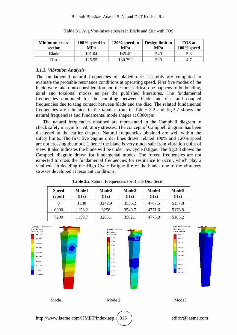
Table 3.1 Avg Von-mises stresses in Blade and disc with FOS
3.1.3. Vibration Analysis
The fundamental natural frequencies of bladed disc assembly are computed to
evaluate the probable resonance conditions at operating speed. First five modes of the
blade were taken into consideration and the most critical one happens to be bending,
axial and torsional modes as per the published literatures. The fundamental
frequencies computed for the coupling between blade and disc and coupled
frequencies due to tang contact between blade and the disc. The related fundamental
frequencies are tabulated in the tabular from in Table: 3.2 and fig.3.7 shows the
natural frequencies and fundamental mode shapes at 6000rpm.
The natural frequencies obtained are represented in the Campbell diagram to
check safety margin for vibratory stresses. The concept of Campbell diagram has been
discussed in the earlier chapter. Natural frequencies obtained are well within the
safety limits. The first five engine order lines drawn related 100% and 120% speed
are not crossing the mode 1 hence the blade is very much safe from vibration point of
view. It also indicates the blade will be under low cycle fatigue. The fig.3.8 shows the
Campbell diagram drawn for fundamental modes. The forced frequencies are not
expected to cross the fundamental frequencies for resonance to occur, which play a
vital role in deciding the High Cycle Fatigue life of the blades due to the vibratory
stresses developed at resonant conditions.
Table 3.2 Natural Frequencies for Blade Disc Sector
Speed
(rpm)
Mode1
(Hz)
Mode2
(Hz)
Mode3
(Hz)
Mode4
(Hz)
Mode5
(Hz)
0 1138 3242.9 3536.2 4767.5 5157.8
6000 1153.2 3258 3549.7 4771.6 5173.8
7200 1159.7 3265.1 3562.1 4775.9 5185.2
Mode1 Mode 2 Mode3
Minimum cross-
section
100% speed in
MPa
120% speed in
MPa
Design limit in
MPa
FOS at
100% speed
Blade 101.04 145.49 540 5.3
Disc 125.55 180.792 590 4.7

Structural and Vibrational Response Analysis of H.P. Bladed Disc Assembly
http://www.iaeme.com/IJMET/index.asp 317 [email protected]
Mode 4 Mode 5
Figure 3.7 Natural Frequencies and Mode Shapes at 6000rpm
Figure 3.8 Campbell Diagram for Obtained Natural Frequencies
3.1.4. Low Cycle Fatigue Life Estimation
In the present work, to compute the low cycle fatigue life of the blades for expected
4000 cycles which roughly comes around 30 to 40 years at the expected life of the
turbine, though many components in the turbine are frequently changed. The blade is
expected to meet requirement since HP stage blade happens to be the key component
in a steam turbine hence the stress developed at blade root are taken into the S-N
curve data is shown in fig.3.9 and fig.3.10 resulting the life of blade happens to be
infinite number of cycles at 100% speed and infinite number of cycles at 120% speed
for blade. The peak stress developed in disc is 596.05MPa at 100% speed results in
1.8119e5 number of cycles is as shown and peak stress at 120% speed result in
1.294e5 number of cycles, though the fatigue life estimated for 120% for all practical
purpose. The estimated life to be taken at 100% speed, the expected life to calculated
based on (Zero maximum Zero) average stress based theory from the analysis

Bharath Bhaskar, Anand. S. N. and Dr.T.Krishna Rao
http://www.iaeme.com/IJMET/index.asp 318 [email protected]
considering size factor, shape factor, surface finish factor etc. The safety factor for the
blade and disc is as shown in fig.3.11 and fig 3.12 is varying from 2.3074 to 15. This
also ensures the safety of the blade at operating conditions.
Figure 3.9 Stress Life(S-N) Curve for Blade Figure 3.10 Stress Life(S-N) Curve for Disc
Figure 3.11 Fatigue Life of Blade Figure 3.12 Fatigue Life of Disc
Figure 3.13 Factor of Safety for Blade and Disc under Fatigue Loading
4. CONCLUSIONS
The considerations for structural, vibration and fatigue analysis is obtained the
following conclusions for the present work.
Structural and Vibrational Response Analysis of H.P. Bladed Disc Assembly
http://www.iaeme.com/IJMET/index.asp 319 [email protected]
1. The radial expansion of blade at operating conditions is safe and found within
the safe limit. Hence there is no wear and tear of blade with the turbine casing
even at higher speeds.
2. The average stress developed in the blade, neck and the minimum disc cross
section at 100% and 120% is also shows the complete safety of the blade and
the disc from total yielding point of view.
3. The calculated natural frequencies should not match with any of the forced
frequency resulting from the running speed of turbine, NPF (nozzle passing
frequency), partial steam admission in the turbine at operating speed.
4. The peak stress developed at blade root filet due to centrifugal spin as resulted
in the LCF of 1.917e5 and 1.8119e5 number of cycles in blade and disc
respectively by meeting the important design requirements from both local
stress-strain approach and stress based (Zero-Max- Zero) fatigue analysis.
Therefore, with this novel work gives an approach for evaluation of a HP stage
Blade in a steam turbine is established in a methodical way and an effort has been
made to formulate the best method to understand and apply the same procedures for
estimation of the strength of the blade and the disc in regular design practice.
REFERENCES
[1] Prof. W.S. Rathod and Khalid Ansari, Modal and Harmonic analysis of
Turbocharger turbine using Finite Element Method, 2(7), July 2013.
[2] Mahajan Vandana N, analysis of blades of axial flow fan using ansys,
Department of Mechanical Engg. S.S.B.T’s College of Engg. and Technology,
Bambhori, Jalgaon.
[3] R.D.Banpurkar, Structural Analysis of Micro Compressor Blades, Dept. of
Mechanical Engineering, Abha Gaikawad Patil Engineering College, Nagpur,
Maharashtra, India.
[4] Sheik Ghouse .M, P. Manivannan, Computational Analysis of Compressor Blade,
International Journal of Innovative Research in Science, Engineering and
Technology, 4(3), March 2015.
[5] C. S. Krishnamoorthy, (1987).Finite Element Analysis, Theory and
Programming, Tata McGraw-Hill Publishing Company Ltd., New Delhi.
[6] Leonid Shabliy and Aleksandr Cherniaev, Optimization of Gas Turbine
Compressor Blade Parameters for Gas-dynamic Efficiency under Strength
Constraints, Samara State Aerospace University, Moskovskoe r, Samara, Russia
JSC, CADFEM-CIS, Avrora st., Samara, Russia
[7] Ahmed abdulhussein jabbar, a. k. rai, p. ravinder reedy & mahmood hasan dakhil,
International Journal of Mechanical and Production Engineering Research and
Development (IJMPERD) 4(1), Feb 2014, 73–94.
[8] Naixing Chen, Hongwu Zhang, Yanji Xu, Weiguang Huang, Blade
Parameterization and Aerodynamic Design Optimization For a 3D Transonic
Compressor Rotor, Proceedings of the 8th International Symposium On
Experimental and Computational Aerothermodynamics of Internal Flows Lyon,
July 2007.
[9] Sanket Kothawade, Aditya Patankar, Rohit Kulkarni and Sameer Ingale,
Determination of Heat Transfer Coefficient of Brake Rotor Disc Using CFD
Simulation. International Journal of Mechanical Engineering and Technology,
7(3), 2016, pp. 276–284.