structural analysis of folded glass plate structures
TRANSCRIPT
Challenging Glass 5 – Conference on Architectural and Structural Applications of Glass Belis, Bos & Louter (Eds.), Ghent University, June 2016.
Copyright © with the authors. All rights reserved. ISBN 978-90-825-2680-6
Structural Analysis of Folded Glass Plate Structures
J. Griffith a, V. Marinov a, S. Marinitsch b, c & M. Teich b a Ove Arup & Partners Ltd, London, UK, [email protected]
b seele GmbH, Gersthofen, Germany c Technische Universitӓt Wien, Vienna, Austria
Folded glass plate structures have the potential to become the next generation of structural glass. By connecting glass plates along their edges and creating a folded plate geometry, glass can be used to transparently self-span large areas without the need for additional supporting structure. An experimental glass connection is used as a basis for this paper. Available test and numerical data is used to create an interaction diagram for this connection, giving allowable axial forces, shear forces and bending moments. Due to the dependency of folded plate structures on geometry, a parametric numerical analysis approach is developed. This captures the global behaviour of the structures whilst also being calibrated against the local behaviour of the connection detail. The approach is based on established techniques for structural glass analysis using the finite element software Strand7. The results are presented graphically, illustrating that connection utilization drives design. It is shown that parametric finite element analysis is a powerful tool to extend feasibility-studies for new shapes and configurations.
Keywords: Glass, Structures, Analysis, Folded Plates, Parametric Analysis
1. Introduction
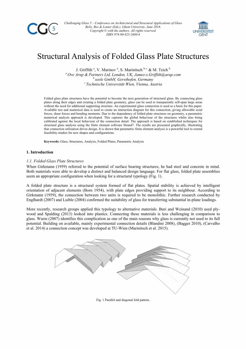
1.1. Folded Glass Plate Structures When Girkmann (1959) referred to the potential of surface bearing structures, he had steel and concrete in mind. Both materials were able to develop a distinct and balanced design language. For flat glass, folded plate assemblies seem an appropriate configuration when looking for a structural typology (Fig. 1).
A folded plate structure is a structural system formed of flat plates. Spatial stability is achieved by intelligent orientation of adjacent elements (Born 1954), with plate edges providing support to its neighbour. According to Girkmann (1959), the connection between two units is required to be monolithic. Further research conducted by Englhardt (2007) and Luible (2004) confirmed the suitability of glass for transferring substantial in-plane loadings.
More recently, research groups applied this typology to alternative materials. Buri and Weinand (2010) used ply-wood and Spalding (2013) looked into plastics. Connecting these materials is less challenging in comparison to glass. Wurm (2007) identifies this complication as one of the main reasons why glass is currently not used to its full potential. Building on available, mainly experimental connection details (Blandini 2008), (Bagger 2010), (Carvalho et al. 2014) a connection concept was developed at TU-Wien (Marinitsch et al. 2015).
Fig. 1 Parallel and diagonal fold pattern.
Challenging Glass 5
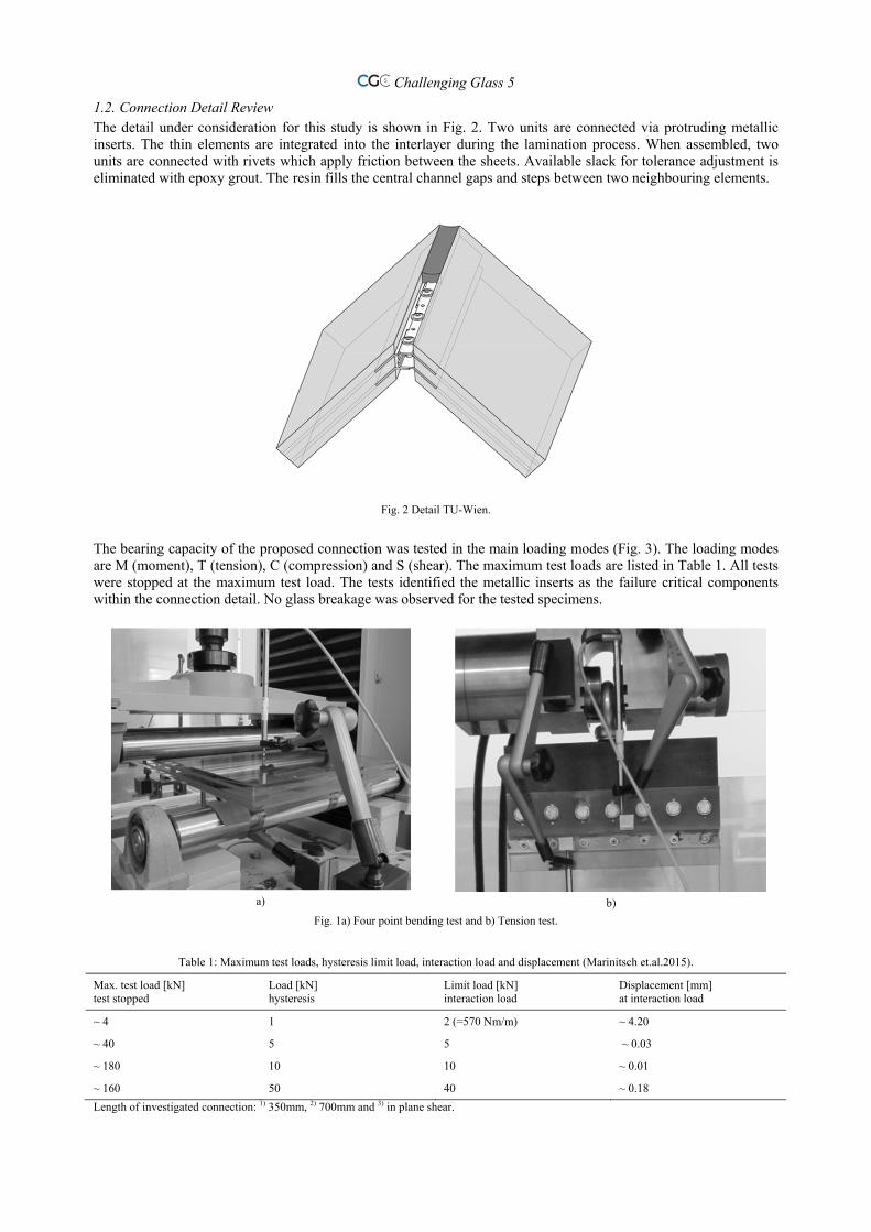
1.2. Connection Detail Review The detail under consideration for this study is shown in Fig. 2. Two units are connected via protruding metallic inserts. The thin elements are integrated into the interlayer during the lamination process. When assembled, two units are connected with rivets which apply friction between the sheets. Available slack for tolerance adjustment is eliminated with epoxy grout. The resin fills the central channel gaps and steps between two neighbouring elements.
Fig. 2 Detail TU-Wien.
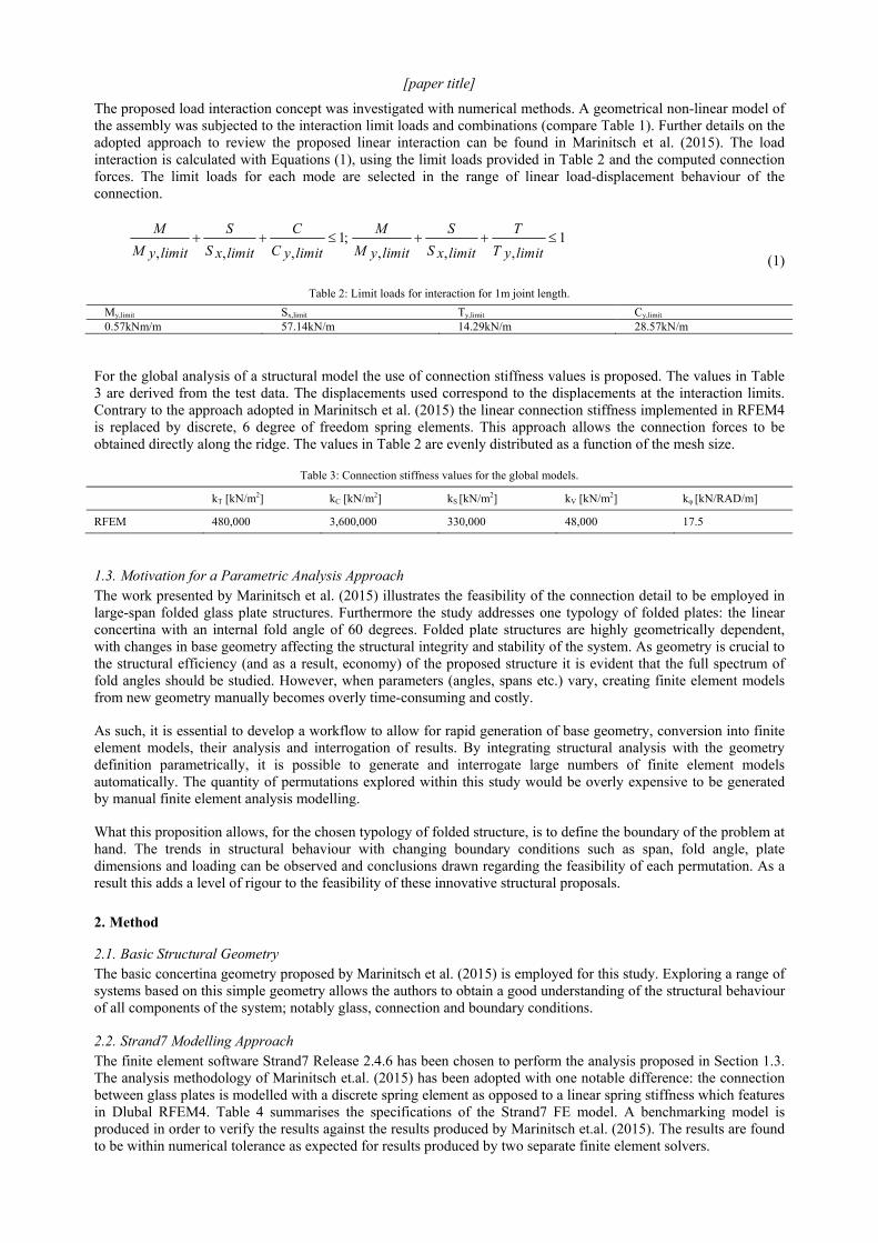
The bearing capacity of the proposed connection was tested in the main loading modes (Fig. 3). The loading modes are M (moment), T (tension), C (compression) and S (shear). The maximum test loads are listed in Table 1. All tests were stopped at the maximum test load. The tests identified the metallic inserts as the failure critical components within the connection detail. No glass breakage was observed for the tested specimens.
a)
b)
Fig. 1a) Four point bending test and b) Tension test.
Table 1: Maximum test loads, hysteresis limit load, interaction load and displacement (Marinitsch et.al.2015).
Max. test load [kN] test stopped
Load [kN] hysteresis
Limit load [kN] interaction load
Displacement [mm] at interaction load
~ 4 1 2 (=570 Nm/m) ~ 4.20
~ 40 5 5 ~ 0.03
~ 180 10 10 ~ 0.01
~ 160 50 40 ~ 0.18
Length of investigated connection: 1) 350mm, 2) 700mm and 3) in plane shear.
[paper title]
The proposed load interaction concept was investigated with numerical methods. A geometrical non-linear model of the assembly was subjected to the interaction limit loads and combinations (compare Table 1). Further details on the adopted approach to review the proposed linear interaction can be found in Marinitsch et al. (2015). The load interaction is calculated with Equations (1), using the limit loads provided in Table 2 and the computed connection forces. The limit loads for each mode are selected in the range of linear load-displacement behaviour of the connection.
1,,,
;1,,,
T itlimy
T
S itlimx
S
M itlimy
M
C itlimy
C
S itlimx
S
M itlimy
M
(1)
Table 2: Limit loads for interaction for 1m joint length.
My,limit Sx,limit Ty,limit Cy,limit 0.57kNm/m 57.14kN/m 14.29kN/m 28.57kN/m
For the global analysis of a structural model the use of connection stiffness values is proposed. The values in Table 3 are derived from the test data. The displacements used correspond to the displacements at the interaction limits. Contrary to the approach adopted in Marinitsch et al. (2015) the linear connection stiffness implemented in RFEM4 is replaced by discrete, 6 degree of freedom spring elements. This approach allows the connection forces to be obtained directly along the ridge. The values in Table 2 are evenly distributed as a function of the mesh size.
Table 3: Connection stiffness values for the global models.
kT [kN/m2] kC [kN/m2] kS [kN/m2] kV [kN/m2] kφ [kN/RAD/m]
RFEM 480,000 3,600,000 330,000 48,000 17.5
1.3. Motivation for a Parametric Analysis Approach The work presented by Marinitsch et al. (2015) illustrates the feasibility of the connection detail to be employed in large-span folded glass plate structures. Furthermore the study addresses one typology of folded plates: the linear concertina with an internal fold angle of 60 degrees. Folded plate structures are highly geometrically dependent, with changes in base geometry affecting the structural integrity and stability of the system. As geometry is crucial to the structural efficiency (and as a result, economy) of the proposed structure it is evident that the full spectrum of fold angles should be studied. However, when parameters (angles, spans etc.) vary, creating finite element models from new geometry manually becomes overly time-consuming and costly.
As such, it is essential to develop a workflow to allow for rapid generation of base geometry, conversion into finite element models, their analysis and interrogation of results. By integrating structural analysis with the geometry definition parametrically, it is possible to generate and interrogate large numbers of finite element models automatically. The quantity of permutations explored within this study would be overly expensive to be generated by manual finite element analysis modelling.
What this proposition allows, for the chosen typology of folded structure, is to define the boundary of the problem at hand. The trends in structural behaviour with changing boundary conditions such as span, fold angle, plate dimensions and loading can be observed and conclusions drawn regarding the feasibility of each permutation. As a result this adds a level of rigour to the feasibility of these innovative structural proposals.
2. Method
2.1. Basic Structural Geometry The basic concertina geometry proposed by Marinitsch et al. (2015) is employed for this study. Exploring a range of systems based on this simple geometry allows the authors to obtain a good understanding of the structural behaviour of all components of the system; notably glass, connection and boundary conditions.
2.2. Strand7 Modelling Approach The finite element software Strand7 Release 2.4.6 has been chosen to perform the analysis proposed in Section 1.3. The analysis methodology of Marinitsch et.al. (2015) has been adopted with one notable difference: the connection between glass plates is modelled with a discrete spring element as opposed to a linear spring stiffness which features in Dlubal RFEM4. Table 4 summarises the specifications of the Strand7 FE model. A benchmarking model is produced in order to verify the results against the results produced by Marinitsch et.al. (2015). The results are found to be within numerical tolerance as expected for results produced by two separate finite element solvers.
Challenging Glass 5
Table 4: Finite element model specification.
Element type Density Material, Stiffness Load
Glass QUAD4-quadrilateral linear shell.
100mm x 100mm; 6000 – 72000 shell elements per model.
Glass, E=70GPa; membrane thickness 26mm; effective bending thickness 26mm (Glass build-up of 8-10-8mm glass with 0.9+1.5+0.9mm SentryGlas interlayer).
Uniform pressure applied normal to shell plane; gravity acceleration applied.
Connection 6 independent DOF discrete, zero length spring (connection).
Spacing 100mm effective.
Test data, Table 3. n/a
Supports Translational supports. Effective pin supports within 300mm either end.
Infinitely stiff. n/a
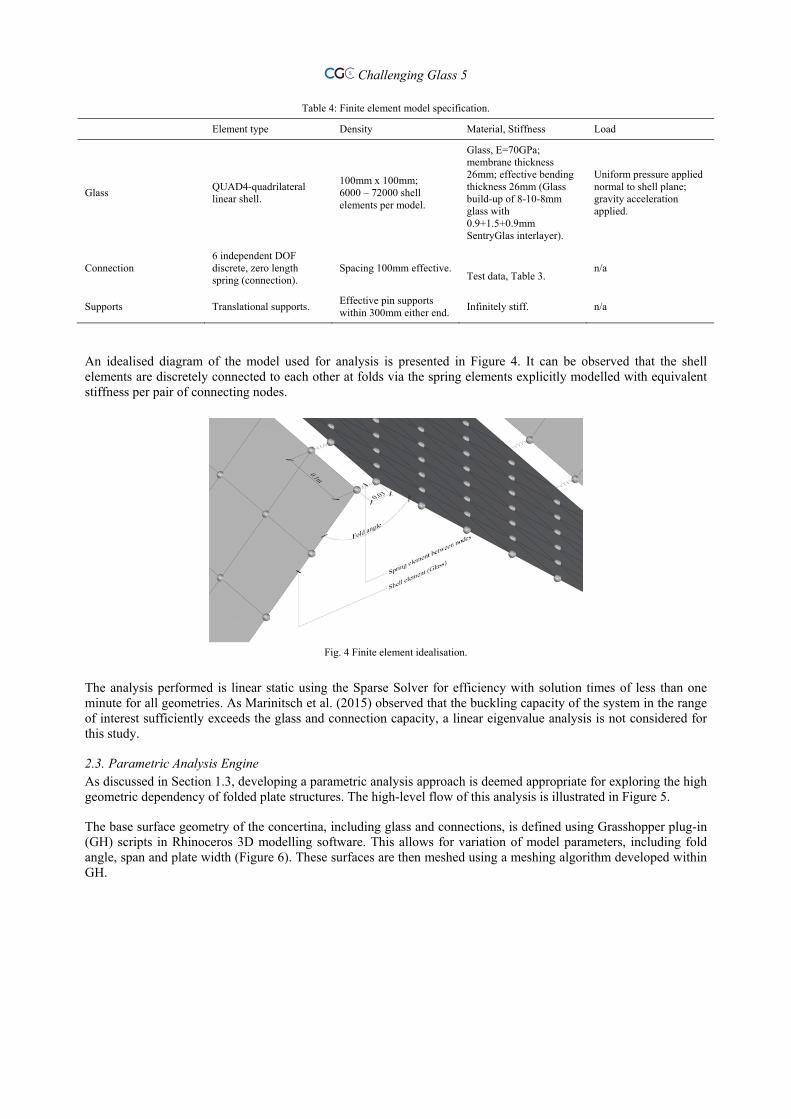
An idealised diagram of the model used for analysis is presented in Figure 4. It can be observed that the shell elements are discretely connected to each other at folds via the spring elements explicitly modelled with equivalent stiffness per pair of connecting nodes.
Fig. 4 Finite element idealisation.
The analysis performed is linear static using the Sparse Solver for efficiency with solution times of less than one minute for all geometries. As Marinitsch et al. (2015) observed that the buckling capacity of the system in the range of interest sufficiently exceeds the glass and connection capacity, a linear eigenvalue analysis is not considered for this study.
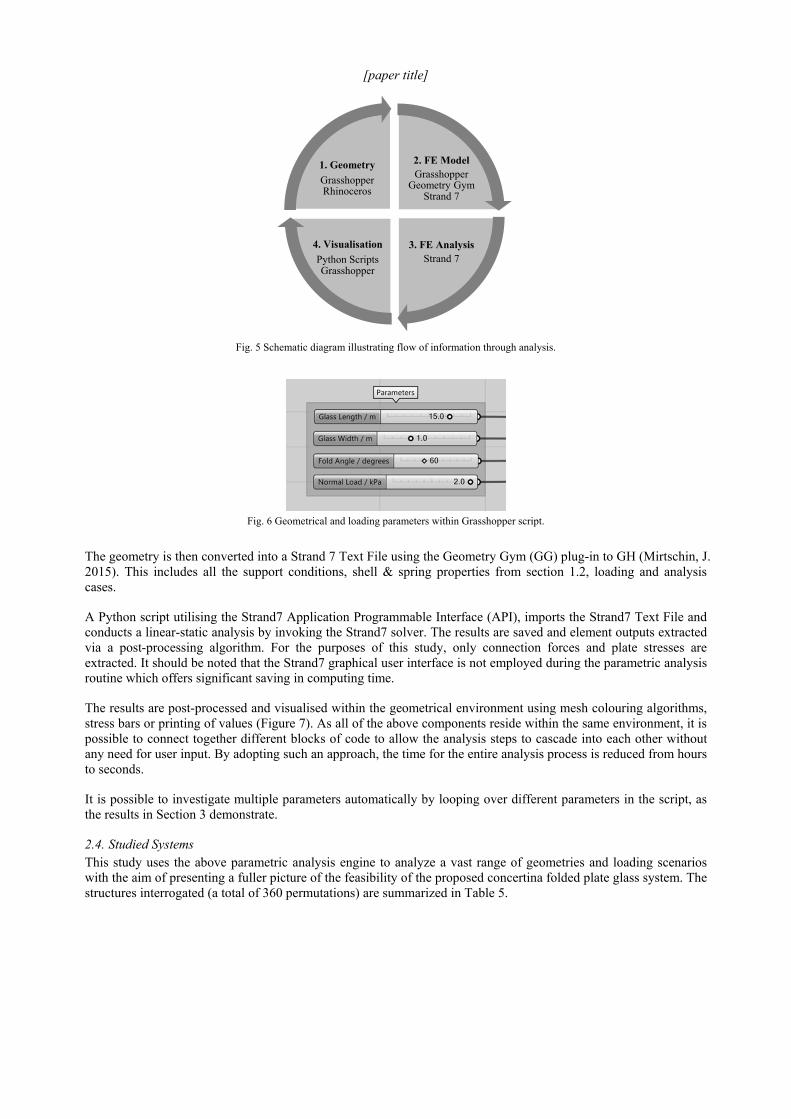
2.3. Parametric Analysis Engine As discussed in Section 1.3, developing a parametric analysis approach is deemed appropriate for exploring the high geometric dependency of folded plate structures. The high-level flow of this analysis is illustrated in Figure 5.
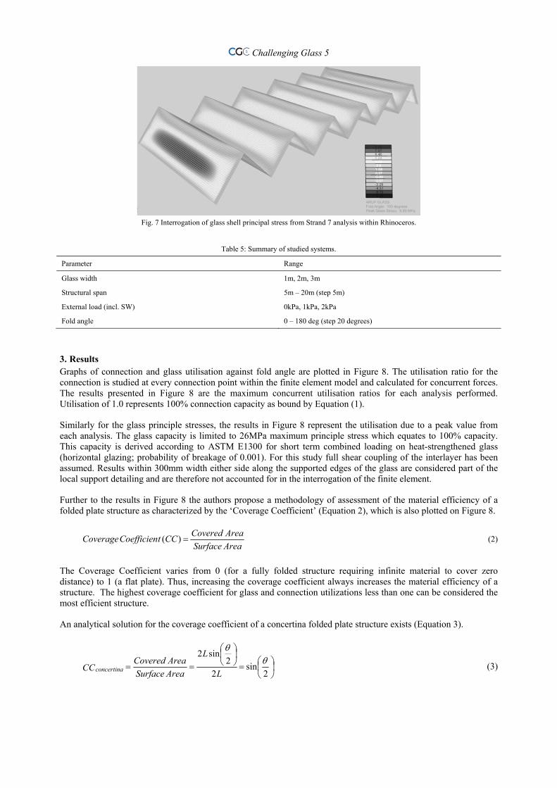
The base surface geometry of the concertina, including glass and connections, is defined using Grasshopper plug-in (GH) scripts in Rhinoceros 3D modelling software. This allows for variation of model parameters, including fold angle, span and plate width (Figure 6). These surfaces are then meshed using a meshing algorithm developed within GH.
[paper title]
Fig. 5 Schematic diagram illustrating flow of information through analysis.
Fig. 6 Geometrical and loading parameters within Grasshopper script.
The geometry is then converted into a Strand 7 Text File using the Geometry Gym (GG) plug-in to GH (Mirtschin, J. 2015). This includes all the support conditions, shell & spring properties from section 1.2, loading and analysis cases.
A Python script utilising the Strand7 Application Programmable Interface (API), imports the Strand7 Text File and conducts a linear-static analysis by invoking the Strand7 solver. The results are saved and element outputs extracted via a post-processing algorithm. For the purposes of this study, only connection forces and plate stresses are extracted. It should be noted that the Strand7 graphical user interface is not employed during the parametric analysis routine which offers significant saving in computing time.
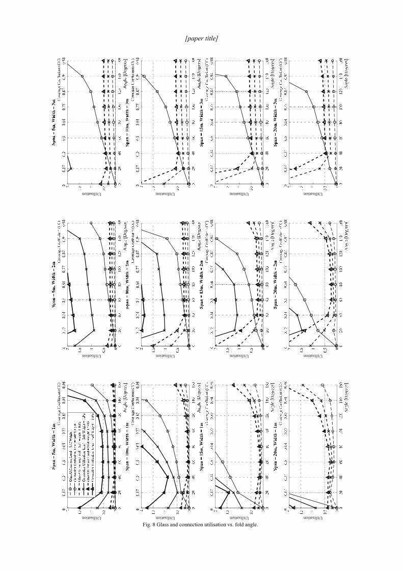
The results are post-processed and visualised within the geometrical environment using mesh colouring algorithms, stress bars or printing of values (Figure 7). As all of the above components reside within the same environment, it is possible to connect together different blocks of code to allow the analysis steps to cascade into each other without any need for user input. By adopting such an approach, the time for the entire analysis process is reduced from hours to seconds.
It is possible to investigate multiple parameters automatically by looping over different parameters in the script, as the results in Section 3 demonstrate.
2.4. Studied Systems This study uses the above parametric analysis engine to analyze a vast range of geometries and loading scenarios with the aim of presenting a fuller picture of the feasibility of the proposed concertina folded plate glass system. The structures interrogated (a total of 360 permutations) are summarized in Table 5.
2. FE ModelGrasshopper
Geometry GymStrand 7
3. FE AnalysisStrand 7
4. Visualisation
Python ScriptsGrasshopper
1. Geometry
GrasshopperRhinoceros
Challenging Glass 5
Fig. 7 Interrogation of glass shell principal stress from Strand 7 analysis within Rhinoceros.
Table 5: Summary of studied systems.
Parameter Range
Glass width 1m, 2m, 3m
Structural span 5m – 20m (step 5m)
External load (incl. SW) 0kPa, 1kPa, 2kPa
Fold angle 0 – 180 deg (step 20 degrees)
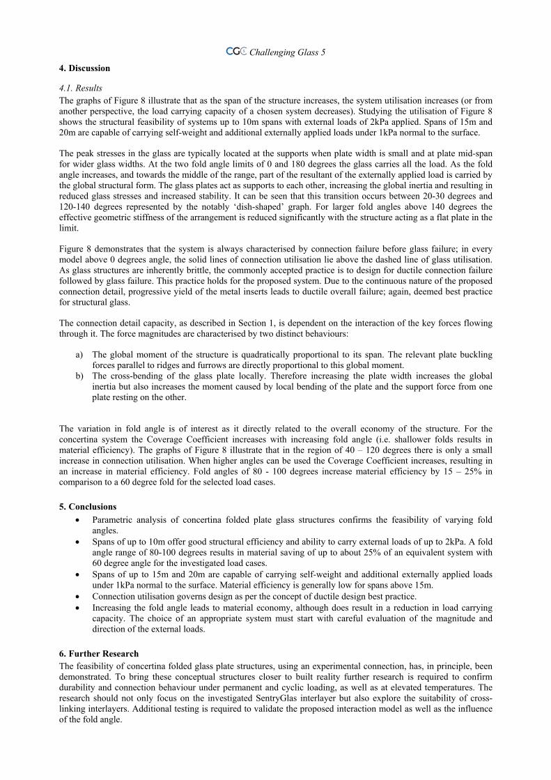
3. Results Graphs of connection and glass utilisation against fold angle are plotted in Figure 8. The utilisation ratio for the connection is studied at every connection point within the finite element model and calculated for concurrent forces. The results presented in Figure 8 are the maximum concurrent utilisation ratios for each analysis performed. Utilisation of 1.0 represents 100% connection capacity as bound by Equation (1).
Similarly for the glass principle stresses, the results in Figure 8 represent the utilisation due to a peak value from each analysis. The glass capacity is limited to 26MPa maximum principle stress which equates to 100% capacity. This capacity is derived according to ASTM E1300 for short term combined loading on heat-strengthened glass (horizontal glazing; probability of breakage of 0.001). For this study full shear coupling of the interlayer has been assumed. Results within 300mm width either side along the supported edges of the glass are considered part of the local support detailing and are therefore not accounted for in the interrogation of the finite element.
Further to the results in Figure 8 the authors propose a methodology of assessment of the material efficiency of a folded plate structure as characterized by the ‘Coverage Coefficient’ (Equation 2), which is also plotted on Figure 8.
AreaSurface
AreaCoveredCCtCoefficienCoverage )( (2)
The Coverage Coefficient varies from 0 (for a fully folded structure requiring infinite material to cover zero distance) to 1 (a flat plate). Thus, increasing the coverage coefficient always increases the material efficiency of a structure. The highest coverage coefficient for glass and connection utilizations less than one can be considered the most efficient structure.
An analytical solution for the coverage coefficient of a concertina folded plate structure exists (Equation 3).
2
sin2
2sin2
L
L
AreaSurface
AreaCoveredCCconcertina (3)
[paper title]
Fig. 8 Glass and connection utilisation vs. fold angle.
Utilisation
Utilisation
Utilisation
Utilisation
Utilisation
Utilisation
Utilisation
Utilisation
Utilisation
Utilisation
Utilisation
Utilisation
Challenging Glass 5
4. Discussion
4.1. Results The graphs of Figure 8 illustrate that as the span of the structure increases, the system utilisation increases (or from another perspective, the load carrying capacity of a chosen system decreases). Studying the utilisation of Figure 8 shows the structural feasibility of systems up to 10m spans with external loads of 2kPa applied. Spans of 15m and 20m are capable of carrying self-weight and additional externally applied loads under 1kPa normal to the surface.
The peak stresses in the glass are typically located at the supports when plate width is small and at plate mid-span for wider glass widths. At the two fold angle limits of 0 and 180 degrees the glass carries all the load. As the fold angle increases, and towards the middle of the range, part of the resultant of the externally applied load is carried by the global structural form. The glass plates act as supports to each other, increasing the global inertia and resulting in reduced glass stresses and increased stability. It can be seen that this transition occurs between 20-30 degrees and 120-140 degrees represented by the notably ‘dish-shaped’ graph. For larger fold angles above 140 degrees the effective geometric stiffness of the arrangement is reduced significantly with the structure acting as a flat plate in the limit.
Figure 8 demonstrates that the system is always characterised by connection failure before glass failure; in every model above 0 degrees angle, the solid lines of connection utilisation lie above the dashed line of glass utilisation. As glass structures are inherently brittle, the commonly accepted practice is to design for ductile connection failure followed by glass failure. This practice holds for the proposed system. Due to the continuous nature of the proposed connection detail, progressive yield of the metal inserts leads to ductile overall failure; again, deemed best practice for structural glass.
The connection detail capacity, as described in Section 1, is dependent on the interaction of the key forces flowing through it. The force magnitudes are characterised by two distinct behaviours:
a) The global moment of the structure is quadratically proportional to its span. The relevant plate buckling forces parallel to ridges and furrows are directly proportional to this global moment.
b) The cross-bending of the glass plate locally. Therefore increasing the plate width increases the global inertia but also increases the moment caused by local bending of the plate and the support force from one plate resting on the other.
The variation in fold angle is of interest as it directly related to the overall economy of the structure. For the concertina system the Coverage Coefficient increases with increasing fold angle (i.e. shallower folds results in material efficiency). The graphs of Figure 8 illustrate that in the region of 40 – 120 degrees there is only a small increase in connection utilisation. When higher angles can be used the Coverage Coefficient increases, resulting in an increase in material efficiency. Fold angles of 80 - 100 degrees increase material efficiency by 15 – 25% in comparison to a 60 degree fold for the selected load cases.
5. Conclusions
Parametric analysis of concertina folded plate glass structures confirms the feasibility of varying fold angles.
Spans of up to 10m offer good structural efficiency and ability to carry external loads of up to 2kPa. A fold angle range of 80-100 degrees results in material saving of up to about 25% of an equivalent system with 60 degree angle for the investigated load cases.
Spans of up to 15m and 20m are capable of carrying self-weight and additional externally applied loads under 1kPa normal to the surface. Material efficiency is generally low for spans above 15m.
Connection utilisation governs design as per the concept of ductile design best practice. Increasing the fold angle leads to material economy, although does result in a reduction in load carrying
capacity. The choice of an appropriate system must start with careful evaluation of the magnitude and direction of the external loads.
6. Further Research The feasibility of concertina folded glass plate structures, using an experimental connection, has, in principle, been demonstrated. To bring these conceptual structures closer to built reality further research is required to confirm durability and connection behaviour under permanent and cyclic loading, as well as at elevated temperatures. The research should not only focus on the investigated SentryGlas interlayer but also explore the suitability of cross-linking interlayers. Additional testing is required to validate the proposed interaction model as well as the influence of the fold angle.
[paper title]
Further research into more complex geometries such as the single kink (reverse fold) illustrated in Figure 1 should be investigated. This could allow for spanning structures over a larger distance due to the increase in arching action from the geometry.
Acknowledgments The authors would like to acknowledge both Jon Mirtschin (Geometry Gym) and the Strand7 Support Team for their help and support in assisting the development of the technology to allow this paper to be written.
References Bagger, A.: Plate shell structures of glass. Studies leading to guidelines for structural design. LAP Lambert Academic Publishing, Saarbrücken
(2010) Blandini, L.: Structural Use of Adhesives in Glass Shells. In: Bos, Louter, Veer (eds) Challenging Glass. Conference on Architectural and
Structural Applications of Glass, pp. 185-191. IOS Press, Amsterdamm (2008) Buri, H., Weinand, Y.: Origami aus Brettsperrholz. DETAIL Zeitschrift für Architektur + Baudetail 10, 1066-1068 (2010) Carvalho, P.d.: Online prototype presentation. University of Minoh, School of Architecture:
http://www.lct.arquitectura.uminho.pt/Default.aspx?tabid=1&pageid=27&l ang=en-US (2015). Accessed 10 June 2015 Englhardt, O.: Flächentragwerke aus Glas – Tragverhalten und Stabilität. PhD-thesis, University of Natural Resources and Life Sciences, Vienna,
Austria (2007) Girkmann, K.: Flächentragwerke. Springer, Wien (1959) Luible, A.: Stabilität von Tragelementen aus Glas. PhD-thesis, EPFL Lausanne, Switzerland (2004) Marinitsch, S., Schranz, Ch., Kolbitsch, A.: Untersuchungen zur Tragfähigkeit eines Verbindungsdetails für Faltwerke aus Glas. Bauingenieur 90
(6), pp. 265-271 (2015) Marinitsch, S., Schranz, Ch., Teich, M.: Faltwerke aus Glas. In: Weller, B., Tasch, S. (eds) Glasbau 2015, pp. 201-211. Ernst & Sohn GmbH &
Co. KG, Berlin (2015) Marinitsch, S., Schranz, C., Teich, M.: Folded plate structures made of glass laminates – a proposal for the structural assessment. Glass Structures
and Engineering (2015) Mirtschin, J.: Geometry Gym. OpenBIM tool for Architects, Engineers and the Construction Industry. Geometry Gym Wordpress.
https://geometrygym.wordpress.com/ (2015). Accessed 8 December 2015 Spalding, V.: Die Kunst der Falte: Faltwerke aus plattenförmigen Kunststoff-Halbzeugen. PhD-thesis, Staatliche Akademie der Bildenden Künste,
Stuttgart (2013) Weller, B., Döbbel, F., Nicklisch, F., Prautzsch, V., Rücker, S.: Geklebte Ganzglaskonstruktion für das Leibniz-Institut für Festkörper- und
Werkstoffforschung in Dresden. Stahlbau 79, 34-40 (2010). doi: 10.1002/stab.201001300 Willaret, P., Meyer, D.: A new folding glass roof for the historic city swimming hall Zürich. In: Proceedings of Glass Performance Days. pp. 622-
624, Tampere, Finland (2011) Wurm, J.: Glas als Tragwerk. Entwurf und Konstruktion selbsttragender Hüllen. Birkhäuser, Basel (2007)

Challenging Glass 5