strombegrenzerkonzepte im vergleich
TRANSCRIPT

Strombegrenzerkonzepte im Vergleich
Markus Abplanalp, 7. Braunschweiger Supraleiterseminar, 6.6.2013

Motivation
Compromise in Power Systems
Why fault current Limiter?
High short-circuit capacity
during normal operation
(low short-circuit impedance)
- Low voltage drops
- High power quality
- High steady-state and transient stability
- Low system perturbations
Low short-circuit capacity
during fault conditions
(high short-circuit impedance)
- Low mechanical stress
- Low thermal stress
- Breakers with reduced switching capacity
Optimal solution FCL
- Low impedance during normal operation
- Fast and effective current limitation
- Automatic and fast recovery
June 14, 2013 | Slide 2
© ABB Group

Definition fault current limiter Overview on fault current limitation measures
Condition based increase of impedance
Small impedance at nominal load
fast increase of impedance at fault
Permanent increase of impedance
at nominal and fault conditions
Topological
measures Fault Current Limiter
Splitting into sub
grids
Introducing a
higher voltage
Splitting of bus
bars
High impedance
transformers
Current limiting
air core reactors
Sequential
tripping
Established
IS-limiter (< 7 kA, < 40.5 kV)
Fuses (< 1 kA, < 36 kV)
FCL CB (< 1 kV)
Novel Concepts
Superconductor
Magnetic Effects
Semiconductor
Hybrid systems
Control
measure
Fault Current Limiting Device
June 14, 2013 | Slide 3
© ABB Group

Voltage
Drain
FCL concepts (selection)
June 14, 2013 | Slide 4
© ABB Group
Lg
Ug
Z
UFCL
Power Electronic
/ Hybrid
Resistive
Is-limiter
Arc Runner
Saturated Iron
Core

i
Y B
Electric circuit Principle
Saturate iron core by DC current
Fault current brings core out of
saturation resulting in large inductance
DC coil often superconducting to
reduce losses
Saturated Iron Core FCL Limitation Principle
June 14, 2013 | Slide 5
© ABB Group
Bs
H
ms
IDC
Limiting element

i
Y
Electric circuit Principle
Saturate iron core by DC current
Fault current brings core out of
saturation resulting in large inductance
DC coil often superconducting to
reduce losses
Saturated Iron Core FCL Limitation Principle
June 14, 2013 | Slide 6
© ABB Group
IDC
IDC
Limiting element

Electric circuit Principle
Saturate iron core by DC current
Fault current brings core out of
saturation resulting in large inductance
DC coil often superconducting to
reduce losses
Saturated Iron Core FCL Limitation Principle
June 14, 2013 | Slide 7
© ABB Group
i
Y
i pC
L
î r
IDC
t
i
ipCL
Îr
Limiting element

i
Y
DY
L0
L0
2 Ir
Inductive Limiter Required voltage drop
during limitation
𝑈𝑔 = 𝑈FCL + 𝜔𝐿𝑔𝐼kCL
𝑈FCL = 𝜔𝐿0𝐼kCL + 𝜔
2 ΔΨ
𝑉 ∝ 𝐴𝑙 ∝𝑁𝐴𝐵𝑠
2
𝜇0𝑁2𝐴
𝑙
=ΔΨ2
𝐿0
∝𝐼r
𝑈𝑔𝑈FCL −
𝜔1
𝐿𝑔+
1
𝐿0
𝐼k2
Best for weak limitation
Saturated Iron Core FCL Design
June 14, 2013 | Slide 8
© ABB Group
Required core volume
Lg
Ug
L
UFCL
UFCL
0 Ik
Ug
ip/2 IkCL
L
V
IkCL 0 Ik ip/2
core volume
L0
Inductive Grid

Grid & Requirements
Voltage 12 kV
Nominal current 1 kArms
Prospective fault 10 kArms
k 1.8
Limited current 8 kArms
Voltage drop @ Ir 1%
FCL
Core volume 0.2 m3
MMF DC coil 190 kA turn
Core height 1 m
Core diameter 20 cm
Windings (per coil) 56
Saturated Iron Core FCL Example
June 14, 2013 | Slide 9
© ABB Group
-20%

Grid & Requirements
Voltage 12 kV
Nominal current 1 kArms
Prospective fault 10 kArms
k 1.8
Limited current 8 kArms
Voltage drop @ Ir 1%
FCL
Core volume 0.2 m3
MMF DC coil 190 kA turn
Core height 1 m
Core diameter 20 cm
Windings (per coil) 56
Saturated Iron Core FCL Example
June 14, 2013 | Slide 10
© ABB Group
-20%
Voltage range MV / HV
Voltage drop
Cooling /
Activation Self
Smart trigger ()
Limitation Inductive
ipCL
IkCL < 50% Ik
IkCL = 80% Ik
Recovery

In grid operation since July 2012 in
Scunthorpe substation
Successfully limited several faults
Superconducting DC coils
Apparent power 24 MVA
Rated voltage 11 kV
Rated current 1250 A
Voltage drop 1%
Fault duration 600 ms
Prospective fault 6.2 kArms
Limited current 5.0 kArms
In future projects ASL plans to use
normalconducting coils
Smart Reactor Status – ASL (Zenergy)
June 14, 2013 | Slide 11
© ABB Group
-20%

In operation since October
2012 at Shigezhuang
substation of Tianjin, China
Superconducting DC coils
Apparent power 300 MVA
Rated voltage 220 kV
Rated current 800 Arms
Voltage drop 1.2%
Prospective fault 50 kArms
Limited current 30 kArms
Recovery time 0.5 s
Saturated Iron Core FCL Status – Innopower
June 14, 2013 | Slide 12
© ABB Group
-40%

Electric circuit Principle
Change in resistance between
superconducting and normalconducting
state of superconductor
Intrinsic detection of fault
Permanent change in resistance
due to heating
Resistive Superconducting FCL Limitation Principle
June 14, 2013 | Slide 13
© ABB Group
Cap layer
Superconductor
Buffer architecture
Substrate
Rcap
Ic(T) |i|
T
Tc
77K
0
R
Limiting element
RCC
Rp

Electric circuit Principle
Change in resistance between
superconducting and normalconducting
state of superconductor
Intrinsic detection of fault
Permanent change in resistance
due to heating
Resistive Superconducting FCL Limitation Principle
June 14, 2013 | Slide 14
© ABB Group
Cap layer
Superconductor
Buffer architecture
Substrate
Rcap
Ic(T) |i|
T
Tc
77K
0
R
R
Rcap
2 Ir Ic |i|
0
Limiting element
RCC
Rp

UFCL
0 Ik
Ug
ip/2 IkCL
R
𝑈𝑔2 = 𝑈FCL
2 + 𝜔𝐿𝑔𝐼kCL2 𝑙CC ∝ 3𝑈FCL𝐼r
Best for strong
limitation
Resistive Superconducting FCL Design
June 14, 2013 | Slide 15
© ABB Group
Lg
Ug
R
UFCL
Inductive Grid
Required voltage drop
during limitation
Required length of
coated conductor
Resistive Limiter
lCC
IkCL 0 Ik ip/2
superconducting
wire length
UFCL
2 Ir Ic |i|
0

Grid & Requirements
Voltage 12 kV
Nominal current 1 kArms
Prospective fault 10 kArms
k 1.8
Limited current 5 kArms
Fault duration 100 ms
Resistive Superconducting FCL Example
June 14, 2013 | Slide 16
© ABB Group
FCL
Length CC 3 5 111 m
= 1.7 km
Parallel resistor 1.4 W
Cap layer 3.8 mm
-50%

Grid & Requirements
Voltage 12 kV
Nominal current 1 kArms
Prospective fault 10 kArms
k 1.8
Limited current 5 kArms
Fault duration 100 ms
Resistive Superconducting FCL Example
June 14, 2013 | Slide 17
© ABB Group
FCL
Length CC 3 5 111 m
= 1.7 km
Parallel resistor 1.4 W
Cap layer 3.8 mm
-50%
Voltage range MV / HV
Voltage drop
Cooling
Activation Self
Smart trigger
Limitation Resistive
ipCL
IkCL < 50% Ik
IkCL = 80% Ik
Recovery

Resistive Superconducting FCL
YBCO thin film on sapphire
1.2 MVA lab test in 2001
Bi-2212 plates 40 25 cm2
3.3 MVA (single phase) lab test in 2003
Bi-2212 cylinders
10 MVA in grid 2004, CURL 10
Several more in grid operation, up to 17 MVA
History
June 14, 2013 | Slide 18
© ABB Group
coated
conductors
coated
conductors
non-supercond.
concepts

Boxberg (Vattenfall)
Auxilliary power in coal plant
In operation since Oct. 2011
Apparent power 12 MVA
Voltage 12 kV
Nominal current 560 A
ECCOFLOW
planned for 2013
Apparent power 42 MVA
Voltage 24 kV
Nominal current 1000 A
Resistive Superconducting FCL Status – Nexans
June 14, 2013 | Slide 19
© ABB Group
more details in the
next talk by Judith
Schramm, Nexans

DOE project with AMSC, SCE,
TCSUH, Nexans, LANL
Single phase test device,
intended for use with parallel
reactor in 115 kV grid coupling
Apparent power 42 MVA
Voltage 30 kV
Nominal current 900 A
Trip current 1.5 In
Fault duration 60 ms
Prospective fault 20 kA
Limited current 2.6 kA
Recovery time 20 s
Project ended 2012
Resistive Superconducting FCL Status – Siemens
June 14, 2013 | Slide 20
© ABB Group
-85%

Electric circuit Principle
Arc accelerated along resistive rails
due to magnetic force for fast increase
of the resistance to 0.8 W in < 1ms
Arc chamber for current interruption at the first current zero crossing
Parallel fixed resistor 2 W
Arc runner Limitation Principle
June 14, 2013 | Slide 21
© ABB Group
Limiting element
Rrails
Rp

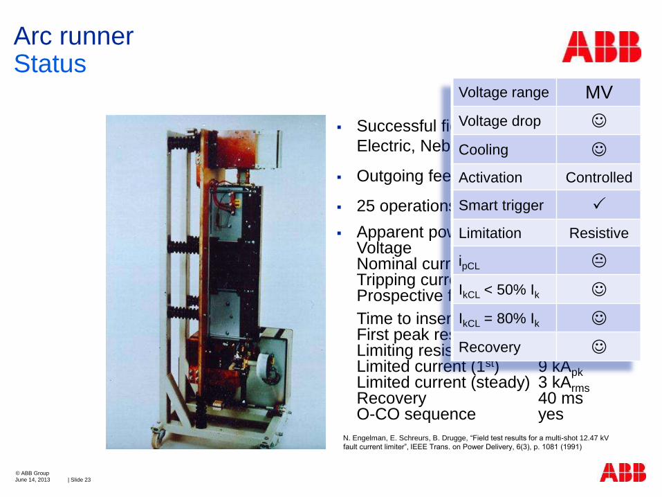
Successful field testing 1987 in Lincoln
Electric, Nebraska
Outgoing feeder
25 operations
Apparent power 25 MVA Voltage 12.47 kV Nominal current 1200 Arms Tripping current 2000 A Prospective fault 11 kArms
Time to insert res. 2 ms First peak resistance 0.8 W Limiting resistance 2.2 W Limited current (1st) 9 kApk Limited current (steady) 3 kArms Recovery 40 ms O-CO sequence yes
Arc runner Status
June 14, 2013 | Slide 22
© ABB Group
N. Engelman, E. Schreurs, B. Drugge, “Field test results for a multi-shot 12.47 kV
fault current limiter”, IEEE Trans. on Power Delivery, 6(3), p. 1081 (1991)
Successful field testing 1987 in Lincoln
Electric, Nebraska
Outgoing feeder
25 operations
Apparent power 25 MVA Voltage 12.47 kV Nominal current 1200 Arms Tripping current 2000 A Prospective fault 11 kArms
Time to insert res. 2 ms First peak resistance 0.8 W Limiting resistance 2.2 W Limited current (1st) 9 kApk Limited current (steady) 3 kArms Recovery 40 ms O-CO sequence yes
Arc runner Status
June 14, 2013 | Slide 23
© ABB Group
Voltage range MV
Voltage drop
Cooling
Activation Controlled
Smart trigger
Limitation Resistive
ipCL
IkCL < 50% Ik
IkCL = 80% Ik
Recovery
N. Engelman, E. Schreurs, B. Drugge, “Field test results for a multi-shot 12.47 kV
fault current limiter”, IEEE Trans. on Power Delivery, 6(3), p. 1081 (1991)

Electric circuit
Limiting element
IS-Limiter Limitation Principle
June 14, 2013
© ABB Group
| Slide 24
Principle
Nominal path interrupted by small
charge
HRC fuse builds up voltage and interrupts or commutes to limiting element

IS-Limiter Limitation Principle
June 14, 2013
© ABB Group
| Slide 25
t
i
Fault current reaches tripping level defined by i and di/dt
Reaction time of electronics ca. 15 ms

IS-Limiter Limitation Principle
June 14, 2013
© ABB Group
| Slide 26
t
i
Fault current reaches tripping level defined by i and di/dt
Reaction time of electronics ca. 15 ms
Opening of nominal connection and commutation to fuse ca. 85 ms
Melting of fuse ca. 500 ms

IS-Limiter Limitation Principle
June 14, 2013
© ABB Group
| Slide 27
t
i
Fault current reaches tripping level defined by i and di/dt
Reaction time of electronics ca. 15 ms
Opening of nominal connection and commutation to fuse ca. 85 ms
Melting of fuse ca. 500 ms
Arcing time of fuse
Total time to interruption < 10 ms

𝑈FCL > 𝑈𝑔 to force
current to zero
Interrupt current at first
voltage zero
Voltage Drain Limiter Required voltage drop
during limitation Required commutation
time
IS-Limiter Design
June 14, 2013
© ABB Group
| Slide 28
𝑡c =2
𝜔 arcsin
𝑖pCL
𝑖p
−arcsin𝑖trip
𝑖p
Lg
Ug
U
UFCL
tc
IkCL
10 ms Ik
0 ms
itrip/2
ip/2
commutation
time
UFCL
0 Ik
Ug
ip/2 IkCL
U
uFCL ; i
0
itrip
t
uFCL
0
i
2Ug ; 2Ik
tc
ipCL
Inductive Grid

𝑈FCL > 𝑈𝑔 to force
current to zero
Interrupt current at first
voltage zero
Voltage Drain Limiter Required voltage drop
during limitation Required commutation
time
IS-Limiter Design
June 14, 2013
© ABB Group
| Slide 29
𝑡c =2
𝜔 arcsin
𝑖pCL
𝑖p
−arcsin𝑖trip
𝑖p
Lg
Ug
U
UFCL
tc
IkCL
10 ms Ik
0 ms
itrip/2
ip/2
commutation
time
UFCL
0 Ik
Ug
ip/2 IkCL
U
uFCL ; i
0
itrip
t
uFCL
0
i
2Ug ; 2Ik
tc
ipCL
Inductive Grid
Is-Limiter Is-Limiter
w Coil
Voltage range MV MV
Voltage drop
Cooling
Activation Controlled Controlled
Smart trigger
Limitation Interrupting Inductive
ipCL
IkCL < 50% Ik
IkCL = 80% Ik
Recovery

Reliability and function proofed since 1960
3000 installations in >80 countries
Product range
IS-Limiter Status
June 14, 2013
© ABB Group
| Slide 30
Rated
voltage
(kV)
Max. rated
current *
(A)
Switching
capability
(kArms)
0.75 5000 140
12 4000 210
17.5 4000 210
24 3000 140
36 2500 140
40.5 2500 140
* For higher rated currents Is-Limiter can be
connected in parallel

Electric circuit
Limiting element
Principle
Nominal path with load commutation
switch and ultra fast disconnector
Main semiconductor breaker to commute into dissipating element
Varistors (or resistors, inductor) as limiting element
Hybrid Limitation Principle
June 14, 2013
© ABB Group
| Slide 31
MOV
4.5 kV IGBT ABB StakPak™ Ultra fast
disconnector
Arrestor (Metal
Oxide Varistor)
UFD

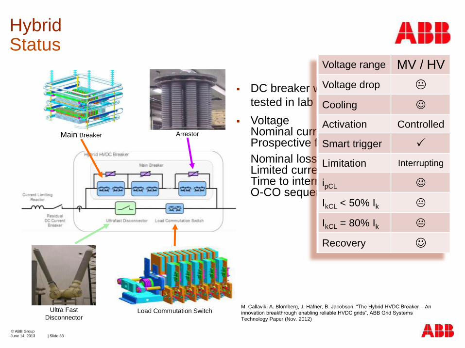
DC breaker with current limiting mode
tested in lab in 2012
Voltage 320 kVDC Nominal current 2600 ADC Prospective fault rise 3.5 kA/ms
Nominal loss <0.01% Limited current <9 kADC Time to interruption <5 ms O-CO sequence yes
Hybrid Status
June 14, 2013
© ABB Group
| Slide 32
Ultra Fast
Disconnector Load Commutation Switch
Arrestor Main Breaker
M. Callavik, A. Blomberg, J. Häfner, B. Jacobson, “The Hybrid HVDC Breaker – An
innovation breakthrough enabling reliable HVDC grids”, ABB Grid Systems
Technology Paper (Nov. 2012)
DC breaker with current limiting mode
tested in lab in 2012
Voltage 320 kVDC Nominal current 2600 ADC Prospective fault rise 3.5 kA/ms
Nominal loss <0.01% Limited current <9 kADC Time to interruption <5 ms O-CO sequence yes
Voltage range MV / HV
Voltage drop
Cooling
Activation Controlled
Smart trigger
Limitation Interrupting
ipCL
IkCL < 50% Ik
IkCL = 80% Ik
Recovery
Hybrid Status
June 14, 2013
© ABB Group
| Slide 33
Ultra Fast
Disconnector Load Commutation Switch
Arrestor Main Breaker
M. Callavik, A. Blomberg, J. Häfner, B. Jacobson, “The Hybrid HVDC Breaker – An
innovation breakthrough enabling reliable HVDC grids”, ABB Grid Systems
Technology Paper (Nov. 2012)

Fault current limiter
Is-limiter
About 3000 installations in more than 80 countries
Superconducting FCL
Today at least 3 resistive, 2 sat. iron core, and 1 hybrid in operation
In grid operation today
June 14, 2013 | Slide 34
© ABB Group
Company Location Year Rating Voltage Current Type Conductor
(MVA) (kV) (A)
ABB Löntsch (Switzerland) 1996 1 10 70 shielded iron core Bi2212
Nexans Siegen (Germany) 2004 10 10 600 resistive Bi2212
Innopower Yunnan (China) 2007 96 35 1600 saturated iron core Bi2223
Nexans Bamber Bridge (GB) 2009 2 12 100 resistive Bi2212
Nexans Boxberg (Germany) 2009 17 12 800 resistive Bi2212
Zenergy San Bernardino (USA) 2009 19 15 740 saturated iron core Bi2223
Nexans Boxberg (Germany) 2011 12 12 560 resistive YBCO cc
KEPRI Incheon (Korea) 2011 25 23 630 hybrid YBCO cc
A2A Reti Elettriche Milan (Italy) 2012 4 10 220 resistive Bi2223
Innopower Shigezhuang (China) 2012 305 220 800 saturated iron core Bi2223
Zenergy / ASL Yorkshire (GB) 2012 24 11 1250 saturated iron core Bi2223
Nexans / ASL Ainsworth lane (GB) 2012 8 12 400 resistive Bi2212
Nexans Mallorca (Spain) and Košice (Slovakia) 2013 42 24 1000 resistive YBCO cc
ASL (Zenergy) Sheffield (GB) 2013 71 33 1250 saturated iron core ?
STCSM Shanghai (China) 2013 7 10 400 resistive YBCO cc
Nexans Essen (Germany) 2013 42 10 2400 resistive YBCO cc
KEPRI JeJu Island (Korea) 2016 534 154 2000 ? YBCO cc
pa
st
futu
re
tod
ay

UFCL
0 Ik
Ug
ip/2 IkCL
L
R
U
Comparison of concepts
June 14, 2013 | Slide 35
© ABB Group
V
IkCL 0 Ik ip/2
core volume
tc
IkCL
10 ms Ik
0 ms
ip/2
commutation
time
lCC
IkCL 0 Ik ip/2
superconducting
wire length
Use for strong limitation
Self activated
Recovery in > 10 s
− Cooling to 77 K
Use for weak limitation
Self activated
Immediate recovery
− Cooling to 77 K or
losses in DC coil
Use for interruption
Smart triggering
± O-CO possible for some
No cooling
Voltage
Drain
