striling engine project final as on 4th june
DESCRIPTION
Striling EngineTRANSCRIPT

FINAL YEAR PROJECT REPORT
UNIVERSITY OF NAIROBI
DEPARTMENT OF MECHANICAL AND MANUFACTURING ENGINEERING
PROJECT REPORT TITLE:
HYBRID STRILING ENGINE
PROJECT CODE: FML 04/2012
This project report is submitted in partial fulfillment of the requirement for the award of the
degree of Bachelor of Science in Mechanical Engineering.
Submitted by:
NJOROGE ALEX KANYONGA F18/1866/2007
WAIRAGU SOLOMON KING’ORI F18/22139/2007
Project supervisor:
PROF. LUTI F.M.
May 2012

DECLARATION
The content of this document is the original work based on our own research and to the best of
our knowledge it has not been presented elsewhere for academic purposes.
NJOROGE ALEX KANYONGA F18/1866/2007
Signed…………………………………. Date: ……………………………
WAIRAGU SOLOMON KING’ORI F18/22139/2007
Signed…………………………………... Date: ………………………………
This project is submitted as part of the Examiners Board requirement for the award of the degree
of Bachelor of Science in Mechanical and Manufacturing Engineering from the University of
Nairobi.
Project supervisor:
PROF. LUTI F.M.
Signed …………………………………. Date: ……………………………….
i

DEDICATION
This project is dedicated to our parents for their love and support during our studies.
ii

ACKNOWLEDGEMENTSFirst, we thank the Almighty God for guiding and giving us strength, peace of mind and grace
that has brought us this far.
We would like to extend our sincere gratitude to the following;
Our project supervisor, Prof. Luti Felix M, we are very grateful for the encouragement, guidance
and assistance that he accorded us from the beginning of the project to its successful completion.
We would like to thank The Chairman’s office (Dept. of Mechanical &Manufacturing
Engineering) for the project funding.
Our special thanks to the UoN Mechanical Engineering workshop staff. With this regard we
would like to single out Mr. Githome, Mr. Anyona, Mr. Okoth, and Mr. Kogi. and Mr. Kimani
for their unwavering assistance in the fabrication and assembly of the engine.
We are grateful to all our family members and friends who supported us all the time to the
completion of this project.
iii

Table of ContentsDECLARATION..............................................................................................................................i
DEDICATION................................................................................................................................ii
ACKNOWLEDGEMENTS...........................................................................................................iii
TABLE OF FIGURES..................................................................................................................vii
NOMENCLATURE.....................................................................................................................viii
OBJECTIVE STATEMENT...........................................................................................................1
1 CHAPTER ONE: BACKGROUND........................................................................................2
1.1 INTRODUCTION:...........................................................................................................2
1.1.1 What’s a Stirling engine?...........................................................................................2
1.1.2 A brief History of the Stirling engine........................................................................3
1.1.3 Why design a Stirling Engine?..................................................................................4
1.1.4 Scope of design..........................................................................................................5
1.1.5 Stirling Engine’s place in a ‘renewable energy’ world.............................................5
2 CHAPTER TWO: LITERATURE REVIEW..........................................................................6
2.1 Introduction.......................................................................................................................6
2.1.1 Basic Components.....................................................................................................6
2.2 Operation and Configuration............................................................................................7
2.2.1 Gamma Configuration...............................................................................................8
2.2.2 Alpha configuration...................................................................................................8
2.2.3 Beta Configuration...................................................................................................10
2.3 Carnot Cycle...................................................................................................................11
2.4 The Stirling Cycle...........................................................................................................12
2.4.1 Basic Stirling cycle..................................................................................................12
2.4.2 Analysis of an ideal Stirling engine with a regenerator...........................................14
2.5 The project calculations..................................................................................................17
2.5.1 Fin Efficiency:.........................................................................................................19
2.5.2 Flywheel size calculation.........................................................................................21
2.6 Solar Energy....................................................................................................................22
2.6.1 The sun.....................................................................................................................22
iv

2.6.2 Harnessing the solar energy.....................................................................................23
2.6.3 Solar concentrator efficiency...................................................................................25
3 CHAPTER THREE: DESIGN AND FABRICATION..........................................................26
3.1 DESIGN..........................................................................................................................26
3.1.1 INTRODUCTION...................................................................................................26
3.1.2 DESIGN PROCESS................................................................................................26
3.1.3 THE DESIGN MANUAL.......................................................................................28
3.2 FABRICATION..............................................................................................................28
3.2.1 INTRODUCTION...................................................................................................28
3.2.2 Project planning.......................................................................................................28
3.2.3 Parts fabrication and assembly................................................................................29
3.3 Assembly.........................................................................................................................31
4 CHAPTER FOUR: FINDINGS AND DISCUSSION...........................................................37
4.1 TESTS RESULTS...........................................................................................................37
4.1.1 TEST 1.....................................................................................................................37
4.1.2 TEST 2.....................................................................................................................37
4.1.3 TEST 3.....................................................................................................................37
4.2 CALCULATIONS..........................................................................................................38
4.2.1 Engine efficiency.....................................................................................................38
4.3 DISCUSSION.................................................................................................................39
4.4 CONCLUSION...............................................................................................................40
4.5 RECOMMENDATIONS................................................................................................40
5 REFERENCES.......................................................................................................................42
APPENDIX A: STIRLING ENGINE DESIGN MANUAL.........................................................43
APPENDIX B BILL OF QUANTITIES.......................................................................................44
APPENDIX C ILLUSTRATIONS................................................................................................45
v

TABLE OF FIGURESFigure 2.1The gamma configuration Stirling engine.......................................................................8Figure 2.2: The Alpha configuration Stirling engine.......................................................................9Figure 2.3: The Beta configuration Stirling engine.......................................................................10Figure 2.4: The Carnot cycle on a T-S diagram............................................................................11Figure 2.5: The Stirling cycle on a P-V & T-S diagram................................................................12Figure 2.6: The Stirling with cycle regenerator on a P-V & T-S diagram....................................14Figure 2.7: The Stirling cycle on a P-V diagram showing M.E.P.................................................17Figure 2.8: Illustration of the cooling fins on the Heat sink cylinder............................................19Figure 2.9: Distribution of solar energy on earth..........................................................................22Figure 2.10: Examples of parabolic reflectors...............................................................................23Figure 2.11: The side and front views of the Stirling engine being heated via solar....................24Figure 3.1: Stirling engine designs drawn using the Rhinoceros Software...................................26Figure 3.2: First revision of the Stirling engine drawn using Autodesk Inventor.........................27Figure 3.3: The Final Stirling Engine Design used in fabrication.................................................27Figure 3.4: Showing The Parts Before And After Assembly........................................................36Figure 5.1: Stirling Engine Technology being made use of in California.....................................45
vi

NOMENCLATUREAces Cross-Sectional area, [m2]
cap Specific heat at p=cost, [J/kg K]
cv Specific heat at V= cost, [J/kg K]
E Effectiveness
h Specific enthalpy, [J/kg]
L Length, [m]
P Pressure, [Pa]
Q Heat, [J]
R Specific gas constant, [J/kg K]
S Entropy, [J/K]
s Specific entropy, [J/kg K]
T Temperature, [K]
u Velocity, [m/s]
V Volume, [m3]
W Work, [J]
K Thermal Conductivity Constant
r Density
Bn The Beale number
vii

OBJECTIVE STATEMENTThis project was set out to explore the practicality of power production from a Hybrid Stirling engine. This would include research, design and fabrication.
“Hybrid” in this sense means that, unlike conventional Stirling engines that are designed with one mode of heating in mind, our engine model would run on different sources of sufficient external heat to generate the desired motion.
In carrying out this project, we were focused on creating an engine model that could utilize heat from biomass, as well as take a “green turn” and take advantage of solar heat by use of solar concentrators.
Our target beneficiaries would be Kenyans living in the marginalized areas with little hope of getting access to electricity. Seeing as these people use biomass for their ordinary energy needs, the success of this project would afford these people a chance to have sustainable subsistent power in their homes.
Further, as the Government commits its resources to achieve the vision 2030, we took the challenge upon ourselves as academia to explore possibilities of aiding in rural electrification, in the wider goal of upgrading Kenyans’ living standards.
In a nutshell, the aims of this project include the following:
Research on working principle of Stirling engines Design of a Stirling engine that could be easily fabricated for small scale subsistence use Fabrication of a prototype Stirling engine and assess its performance Give a recommendation from the findings and a way forward
Page | 1

1 CHAPTER ONE: BACKGROUND
1.1 INTRODUCTION:
1.1.1 What’s a Stirling engine?
A Stirling engine is a heat engine operating by cyclic compression and expansion of air at different temperature levels such that there is a net conversion of heat energy to mechanical work.
Like the steam engine, the Stirling engine is traditionally classified as an external combustion engine, as all heat transfers to and from the working fluid take place through the engine wall. This contrasts with an internal combustion engine where heat input is by combustion of a fuel within the body of the working fluid. Unlike a steam engine’s (or more generally a Rankine cycle engine’s) usage of a working fluid in both of its liquid and gaseous phases, the Stirling engine encloses a fixed quantity of air.1
As is the case with other heat engines, the general cycle consists of compressing cool gas, heating the gas, expanding the hot gas, and finally cooling the gas before repeating the cycle. The efficiency of the process is narrowly restricted by the efficiency of the Carnot cycle, which depends on the temperature between the hot and cold reservoir.
The Stirling engine is exceptional for of its high efficiency compared to steam engines, quiet in operation and the ease with which it can use almost any heat source. This is especially significant as the prices of conventional fuel prices rise in a more “green cautious” world.
Competition from Internal combustion
The invention of the internal combustion engine in the 1900’s put the nail on the coffin for the Stirling type of engine because it generated more power and proved to be more practical in the automobile industry.
Due to the rigorous solar energy exploration taking place in the developed economies, this old technology is being given a newer and fresher approach.
In the Kenyan scenario, the Stirling engine hopes to offer energy to rural and marginalized areas where the most common sources of energy include:
Biomass fuel –from burning of charcoal, firewood, rice husks, coal, maize cobs among others
Biogas- which has become of great use in the rural areas for both cooking and lighting Solar heating- which has made its debut in the rural areas as an alternative means of
cooking energy through use of solar concentrators.
1 http://en.wikipedia.org/wiki/Stirling_engine
Page | 2

1.1.2 A brief History of the Stirling engine
Reverend Robert Stirling
On September 27, 1816, Church of Scotland minister Robert Stirling applied for a patent for his economizer in Edinburgh, Scotland. The device was in the form of an inverted heat engine, and incorporated the characteristic phase shift between the displacer and piston that we see in all Stirling Engines today. 2
The engine also featured the cyclic heating and cooling of the internal gas by means of an external heat source, but the device was not yet known as a Stirling Engine. That name was coined nearly one hundred years later by Dutch engineer Rolf Meijer to describe all types of closed cycle regenerative gas engines.
Stirling originally regarded his engine as a perpetual motion machine of the second kind (i.e. all heat supplied would be converted into work even though his original hot air engine did not include a cooling system.
Due to the invention of the more powerful internal combustion engine at the middle of the 19 th
century, the Stirling technology was abandoned. But even so, the Stirling engine had an extra advantage over the steam engine due to its low operating cost. Also, the steam engine was prone to major failures like explosions. The only major problem with the Stirling engine was its tendency to fail when the cylinder being heated became too hot.
Although improvements were made to curb up the problem, stiff competition from the internal combustion engine forced the hot air engine out of the commercial scene.
Over the years, researchers have continued on Stirling engines, working out many of the design solutions that are used today in low temperature differential Stirling engines.
1.1.3 Why design a Stirling Engine?
In the country’s Vision 2030, the government committed itself to provide affordable universal electricity to its citizens.3To achieve this goal, the academia and investors should work closely
2 http://www.kontax.co.uk/docs/history
Page | 3

and come up with a sustainable solution. To this end, for our final year project, we took the challenge upon ourselves to design and fabricate a small subsistent power generator.
This project aims to provide affordable electricity to the people in the marginalized parts of our country. Places in focus include Northern Kenya, the Coastal strip, and the remote upcountry. These marginalized parts of the country present the biggest challenge to supply affordable power. Compounding the complexity of this challenge, these places do not have economic significance for the national power distribution company, KPLC to invest in power transmission lines.
With this conspicuous power vacuum in sight, we set out to design an alternative source of power. To achieve this, we intended to use the locally available sources of energy, such as charcoal, firewood and biomass fuel, to generate subsistence power for domestic consumption. Thus, we sought to find a transducer that could convert the low calorific sources of energy available, while having economic sense at the back of our minds.
The Stirling engine was the perfect solution.
Our idea was to model a special Stirling engine that could generate power from both an open fire, such as a jiko or firewood stove, and have the potential to generate power on a sunny day using a solar concentrator. This ingenious idea would take advantage of both the available energy while taking a “green” turn and utilizing solar heat to supplement the power generated. Thus the HYBRID CONCEPT.
In addition to taking advantage of the local energy sources, the simplicity in fabrication of a Stirling engine meant that the overall cost of a unit would be within reach for many.
In the preliminary design, we hoped to achieve about 300rpm from the engine arrangement, and a potential of about 100watts. This in our view would be enough power to light a couple of energy saving bulbs, while at the same time powering a small FM tuner, and charging a mobile phone for the family.
This subsistence and sustainable source of power would have far reaching benefits to the marginalized communities. For instance, with this power source, a local green grocer would have electricity to extend trading hours, while children would have light to extend study hours.
All these benefits would have positive compounding benefits to Kenya, and aid the government in attaining the ambitious Vision 2030.
3 Kenya Vision 2030, Harnessing strategic natural resources: “The potential for Kenya to develop bio-resources for medicinal, industrial and other products is recognized”
Page | 4

1.1.4 Scope of design
The hybrid Stirling engine we designed and fabricated was in two pieces: a normal Stirling engine that could be heated externally using an open flame and a detachable solar concentrator that could be placed in front of the Stirling engine to take advantage of solar heat.
A gamma configuration of the engine was chosen, whose working shall be explained further in this report.
The solar concentrating unit consisted of a solar reflector, similar to the ones being used in solar cookers in the most rural areas. Its design was simple and with the right focal length in the curved mirror, the heating of the displacer head would be most efficient.
The aim of choosing this design was to make the manufacturing cost of this engine low and keep it simple. The design and fabrication of the engine are also documented in this report.
1.1.5 Stirling Engine’s place in a ‘renewable energy’ world
Countries such as India have made investments in simple renewable energy solutions that have been able to make rural electrification possible to the poor. Companies such as Husk power systems4 in India, generate electricity by burning rice husks in CNG5 engines to produce electricity.
In the US, use of Stirling engines as a source of renewable energy is being explored. Companies such as Stirling Engine Systems plan to invest in large solar Stirling engines that generate power in excess of 500MW.
By 2030, the Kenyan government hopes get all Kenyans to be dependent on clean and efficient renewable sources of energy. The initial phases have been witnessed through the installation of wind farms at the Ngong hill and a lot of investment in Turkana on solar projects.
We view that the Stirling engine would also be an idea worth looking into. By investing into the research of this technology, with time, better and more compact & affordable models can be built for commercialized purposes and thus the goal of achieving close to 100% rural electrification will not seem like a pipe dream.
Thus early investment in this technology by the government would be a boost for the country’s Energy Grid in future.
4 http://www.huskpowersystems.com5 CNG Engine- Compressed Natural Gas Engine
Page | 5

2 CHAPTER TWO: LITERATURE REVIEW
2.1 Introduction The Stirling engine has over the years evolved. The most common configurations include the Alpha, Beta and Gamma. These vary in the arrangement of the different parts including the displacer, piston and flywheel.
The Stirling engine operates on the Stirling cycle that has a theoretical efficiency close to the Carnot efficiency. In the theory developed later, it is noted that addition of a regenerator in the configuration improves the overall performance and increases the output power of the system.
2.1.1 Basic Components
A Stirling engine consists of a number of basic components, which may vary in design depending on the type and configuration. The most basic are outlined as follows:
Power Piston and Cylinder
This consists of a piston head and connecting rod that slides in an air tight cylinder. The power piston is responsible for transmission of power from the working gas to the flywheel. In addition, the power piston compresses the working fluid on its return stroke, before the heating cycle. Due to the perfect air tight requirement, it is the most critical part in design and fabrication.
Displacer Piston and Cylinder
The displacer is a special purpose piston, used to move the working gas back and forth between the hot and cold heat exchangers. Depending on the type of engine design, the displacer may or may not be sealed to the cylinder, i.e. it is a loose fit within the cylinder and allows the working gas to pass around it as it moves to occupy the part of the cylinder beyond.
Source of Heat
The source of heat may be provided by the combustion of fuel, and since combustion products do not mix with the working fluid, the Stirling engine can run on an assortment of fuels. In addition, other sources such as solar dishes, geothermal energy, and waste heat may be used. Solar powered Stirling engines are becoming increasingly popular as they are a very environmentally friendly option for power production.
Flywheel
The flywheel is connected to the output power of the power piston, and is used to store energy, and provide momentum for smooth running of the engine. It is made of heavy material such as steel, for optimum energy storage.
Page | 6

Regenerator
It is an internal heat exchanger and temporary heat store placed between the hot and cold spaces such that the working fluid passes through it first in one direction then in the other. Its function within the system is to retain heat which would otherwise be exchanged with the environment. It thus enables the thermal efficiency of the cycle to approach the limiting Carnot efficiency.
On the flip side, the presence of regenerator (usually a matrix of fine steel wool), increases the “dead space” (unswept volume). This leads to power loss and reduces efficiency gains from the regeneration.
Heat Sink
The heat sink is typically the environment at ambient temperature. For small heat engines, finned heat exchangers in the ambient air suffice as a heat sink. In the case of medium to high power engines, a radiator may be required to transfer heat from the engine.
2.2 Operation and Configuration Since the Stirling engine is a closed cycle, it contains a fixed mass of gas called the "working fluid", most commonly air, hydrogen or helium. In normal operation, the engine is sealed and no gas enters or leaves the engine. No valves are required, unlike other types of piston engines. The Stirling engine, like most heat engines, cycles through four main processes: cooling, compression, heating and expansion. This is accomplished by moving the gas back and forth between hot and cold heat exchangers, often with a regenerator between the heater and cooler. The hot heat exchanger is in thermal contact with an external heat source, such as a fuel burner, and the cold heat exchanger being in thermal contact with an external heat sink, such as air fins. A change in gas temperature will cause a corresponding change in gas pressure, while the motion of the piston causes the gas to be alternately expanded and compressed.
When the gas is heated, because it is in a sealed chamber, the pressure rises and this then acts on the power piston to produce a power stroke. When the gas is cooled the pressure drops and this means that less work needs to be done by the piston to compress the gas on the return stroke, thus yielding a net power output.
In summary, the Stirling engine uses the temperature difference between its hot end and cold end to establish a cycle of a fixed mass of gas, heated and expanded, and cooled and compressed, thus converting thermal energy into mechanical energy. The greater the temperature differences between the hot and cold sources, the greater the thermal efficiency. The maximum theoretical efficiency is equivalent to the Carnot cycle; however the efficiency of real engines is less than this value due to friction and other losses.
Page | 7

The specific operation of Stirling engines differs from one configuration type to another. These are distinguished by the way they move air between the hot and cold sides of the cylinder. There are three most common basic configurations:
Gamma type: This design also uses a mechanical displacer to push the working gas between the hot and cold sides of the cylinder, but the displacer is housed in a separate cylinder for easier mechanical fabrication.
Alpha type: This design has independent cylinders and a gas driven between the hot and cold spaces.
Beta type: This design uses an insulated mechanical displacer to push the working gas between the hot and cold sides of the cylinder. The displacer piston runs though the power piston, for less “dead space”.
2.2.1 Gamma Configuration
A gamma Stirling is simply a beta Stirling in which the power piston is mounted in a separate cylinder alongside the displacer piston cylinder, but still connected to the same flywheel. The gas in the two cylinders can flow freely between them and remain a single body. This configuration produces a lower compression ratio but mechanically simpler and often used in multi-cylinder Stirling engines.
Figure 2 . 1 The gamma configuration Stirling engine 6
2.2.2 Alpha configuration
An Alpha Stirling contains two pistons in separate cylinders, one hot and one cold. The hot cylinder is situated inside the high temperature heat exchanger and the cold cylinder is situated inside the low temperature heat exchanger. This type of engine has a high-to-power volume ratio but has technical problems due to the usually high temperature of the hot piston and durability of its seals.
6 http://en.wikipedia.org/wiki/Stirling_engine
Page | 8

1. Most of the working gas is in contact with the hot cylinder walls, it has been heated and expansion has pushed the hot piston to the bottom of its travel in the cylinder. The expansion continues in the cold cylinder, which is 90° behind the hot piston in its cycle, extracting more work from the hot gas.
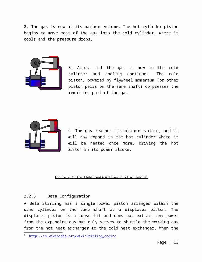
2. The gas is now at its maximum volume. The hot cylinder piston begins to move most of the gas into the cold cylinder, where it cools and the pressure drops.
3. Almost all the gas is now in the cold cylinder and cooling continues. The cold piston, powered by flywheel momentum (or other piston pairs on the same shaft) compresses the remaining part of the gas.
4. The gas reaches its minimum volume, and it will now expand in the hot cylinder where it will be heated once more, driving the hot piston in its power stroke.
Figure 2 . 2 : The Alpha configuration Stirling engine 7
2.2.3 Beta Configuration
A Beta Stirling has a single power piston arranged within the same cylinder on the same shaft as a displacer piston. The displacer piston is a loose fit and does not extract any power from the expanding gas but only serves to shuttle the working gas from the hot heat exchanger to the cold
7 http://en.wikipedia.org/wiki/Stirling_engine
Page | 9

heat exchanger. When the working gas is pushed to the hot end of the cylinder it expands and pushes the power piston. When it is pushed to the cold end of the cylinder it contracts and the momentum of the machine, usually enhanced by a flywheel, pushes the power piston the other way to compress the gas. Unlike the alpha type, the beta type avoids the technical problems of hot moving seals.
1. Power piston (dark grey) has compressed the gas, the displacer piston (light grey) has moved so that most of the gas is adjacent to the hot heat exchanger.
2. The heated gas increases in pressure and pushes the power piston to the farthest limit of the power stroke.
3. The displacer piston now moves, shunting the gas to the cold end of the cylinder.
4. The cooled gas is now compressed by the flywheel momentum. This takes less energy, since when it is cooled its pressure drops.
Figure 2 . 3 : The Beta configuration Stirling engine
Page | 10

2.3 Carnot Cycle 8 Carnot, a French Scientist showed that the most efficient possible cycle is one in which all the heat supplied is at one fixed temperature, and all the heat rejected is rejected at a lower temperature. The cycle therefore consists of two isothermal processes joined by two adiabatic processes. Since all processes are reversible, then the adiabatic processes in the cycle are also isentropic. The cycle is most conveniently represented on a T-S diagram as shown below9.
Figure 2 . 4 : The Carnot cycle on a T-S diagram
It can be seen that the gross heat supplied Q1 is given by the area 41BA4,
Q 1=area 41 BA 4=T 1(sB−s A)
Similarly, the net heat supplied, ΣQ, is given by the area 41234,
ΣQ=(T 1−T2 )(sB−s A)
Hence the Carnot cycle efficiency is:
ηCarnot=(T 1−T 2 )(sB−sA)
T1(sB−sA )
ηCarnot=1−T 2
T 1(2.1)
8 Thermodynamics: An Engineering Approach, 5th edition by Yunus A. Çengel and Michael A. Boles, Chpt6
9 T.D. EASTTOP and A. McCONKEY,2009, Fifth impression, Applied Thermodynamics for engineering technologists. Chapter 5: Heat Engine Cycle, 163-165
Page | 11

2.4 The Stirling Cycle
2.4.1 Basic Stirling cycle
The Stirling cycle comes closest to the Carnot cycle efficiency while having a higher work ratio. Despite the fact that the efficiency may not be practical in real fabrication and testing, the Stirling engine gives the best output.
The idealized Stirling cycle consists of four thermodynamic processes acting on the network of the fluid;
i. 2-3: Isothermal expansion : the expansion space and associated heat exchanger are maintained at a constant high temperature and the gas undergoes isothermal expansion absorbing heat from the heat source.
ii. 3-4: Constant volume heat removal : the gas is passed through a regenerator where it cools transferring heat to the regenerator for use in the next cycle.
iii. 4-1: Isothermal compression : the compression space and associated heat exchanger are maintained at a constant low temperature so that the gas undergoes isothermal compression, rejecting heat to the cold sink.
iv. 1-2: Constant volume heat addition : the gas passes back through the regenerator where it recovers much of the heat transferred in (2) above, heating up on its way to the expansion space.
Figure 2 . 5 : The Stirling cycle on a P-V & T-S diagram
Theoretically, heat is supplied to the working fluid in the process 2-3 where the gas expands isothermally (T2 = T3). Further, heat is rejected to an external heat sink in the process 4-1 where the gas is compressed isothermally (T1=T4). The two isothermals are connected by the constant volume processes 1-2 and 3-4, during which the temperature changes are equal to (T2 - T1).
Page | 12

Heat supplied from the hot source:
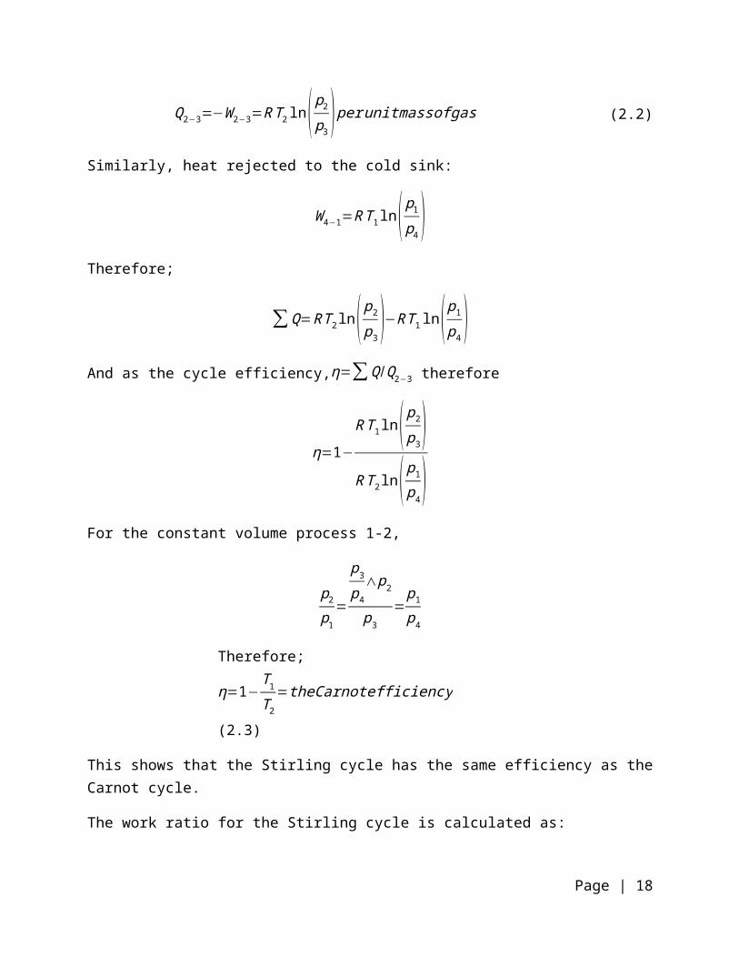
Q2−3=−W 2−3=R T2 ln( p2
p3) perunitmassofgas (2.2)
Similarly, heat rejected to the cold sink:
W 4−1=R T1 ln( p1
p4)
Therefore;
∑Q=R T2 ln( p2
p3)−R T 1 ln( p1
p4)
And as the cycle efficiency,η=∑ Q /Q2−3 therefore
η=1−
R T1 ln( p2
p3)
RT 2 ln( p1
p4)
For the constant volume process 1-2,
p2
p1
=
p3
p4
∧p2
p3
=p1
p4
Therefore;
η=1−T1
T2
=theCarnotefficiency (2.3)
This shows that the Stirling cycle has the same efficiency as the Carnot cycle.
The work ratio for the Stirling cycle is calculated as:
Workratio= network outputgrossworkoutput
=−W 2−3+W 4−1
−W 2−3
¿∑ Q
Q2−3
=cycleefficiency ,η (2.4)
I.e. since −W 2−3=Q2−3
Page | 13

2.4.2 Analysis of an ideal Stirling engine with a regenerator
Below is a plot of P-V diagram with the regenerator effect shown.
Figure 2 . 6 The Stirling with cycle regenerator on a P-V & T-S diagram
In most applications, the regenerator is a wire mesh matrix that is placed between the heater and the cooler. It acts as a thermal sponge.
The effectiveness of the refrigerator, E is defined as:
E=T 2'−T1
T 3−T 1
(2.5)
Therefore the efficiency of a Stirling engine changes because the heat transferred changes to Q2'−3
This is seen to change from the Stirling cycle efficiency,
ηE (engine efficiency )=W x
Q s
Page | 14

Where Wx= net work energy outputQs=heat energy supplied
W x=W 3−4+W 1−2
¿∫3
4
P dv+∫1
2
P dv
PV=MRT , assuming perfect gas
W x=MRT 3∫3
4 dv
v+MRT 1∫
1
2 dv
v
¿ MRT 3 ln( v4
v3)+MRT 1 ln( v2
v1)
¿ MRT 3 ln( v4
v3)−MRT 1 ln( v1
v2)
¿ MRT 3 ln (rv )−MRT 1 ln (rv ) (2.6)10
Where rv=v4
v3
=v1
v2
, i .e the engine cycle compressionratio
Further;
W x=MR ln (rv ) (T 3−T 1 )
Defining T1
T3
=(rt ) , iethe engine temperature ratio
Hence,
W x=MR ln (rv )T 3 ( 1−(rt ) )
Since, C p−C v=R
Cp
C v
−1= RC v
10 T.D. EASTTOP and A. McCONKEY,2009, Fifth impression, Applied Thermodynamics for engineering technologists. Chapter 5: Heat Engine Cycle, 163-165
Page | 15
γ−1= RC v
R=C v (γ−1 )
Thus substituting R into the equation of work output,
W x=M C v T3−(1−(rv ) ) ( γ−1 ) ln (rv ) (2.7)
Therefore with the temperature and compression ratios and assuming a mass of gas contained, theoretical work output can be estimated.
Next, to access heat input to the engine;
Qs=Q2'3+Q34
Q2'3
=M C v (T3−T2' )
Q34=MR T3 ln (rv )
Thus,
Qs=M C v (T3−T2' )+MRT 3 ln (rv )
But,R=C v (γ−1 )
Qs=M C v (T3−T2' )+M C v (γ−1 ) ln (rv )
Qs=M C v [ (T 3−T 2' )+( γ−1 ) ln (rv ) ]Introducing the generator effectiveness, E,
Such that, T 2'=T 3 [ E+(1−E ) (rv ) ]
Thus,
Qs=M C v T 3 [ (1−E ) (1−(rt ) )+(γ−1 ) ln (rv ) ] (2.8)
Thus the thermal efficiency is;
ηE=W x
Q s
=M C v ln (rv ) T 3 ( γ−1 ) (1− (rt ) )
M C v T 3 [ (1−E ) (1−(rt ) )+( γ−1 ) ln (rv ) ]
Page | 16

¿(γ−1)¿¿
Assuming an ideal effectiveness of the regenerator, E=1, thus,
ηE=(γ−1)(1−(rt ) ) ln (rv )
(γ−1 ) ln (rv )
¿1−(rt ) (2.9)
But,T1
T3
=(rt ) , iethe engine temperature ratio
ηE=1−T 1
T 3
, same asCarnot∧Stirling efficiency
Next, we define a dimensionless work output parameter,W othat is formulated on the ideal engine that has been described.
W o=Indicated mean effective pressure
P1
Where the mean effective pressure (M.E.P) is given by equivalent area as occupied by the enclosed P-V area
Figure 2 . 7 : The Stirling cycle on a P-V diagram showing M.E.P
The shaded area is equivalent to the enclosed area.
Thus,
Page | 17

W o=(1− (rt )) (rv ) ln (rv )(rt ) ( γ−1 )
(2.10)
The above equation can be used to give an estimate of the size and power output of an engine (in terms of speed and pressure).
2.5 The project calculations We intended to design a small Stirling engine with an output of approximately 50W and test how much power can be tapped from it.
The engine was to be heated by solar heat, but for the fabrication, we intended to use a torch flame.
Some of the designs we made were based on two approaches:
a) The Mean Effective pressure analogy;
Assuming we achieve a temperature ratio of 600oC:50oC (hot to cold)
From equation (4) derived earlier;
W o=(1− (rt )) (rv ) ln (rv )(rt ) ( γ−1 )
Where approximately,
(rt )=temperature ratio=(50+273.15)(600+273.15)
=0. 37
(rv )=compressionratio=v1
v2
=75 0 × 103mm3
125 × 103mm3 =6
Thus,
W o=(1−0.37 )× 6×ln (6 )
0.37×0.4=45Watts
With the above assumptions of temperature and compression ratios, the Stirling engine designed can output an estimated ≈45Watts
Page | 18

It is noted that the values of the volume are taken from the model parameters, while the values for the temperature are taken from the desired design parameters.
b) Beale equation:
The power output from Stirling engine can be estimated in theory by Baele equation11.
Power (W )=Nb × Meaneffective Pressure∈MPa× Swept volume ( cm3 ) × Rotation∈Hz
(2.11)
Where Nb is the Baele number=0.1112
Designing the swept volume to be 10cm long and 4cm in diameter,
Swept volume=π ×( 42
4 )×10=125.7 cm3
From reference empirical values12, taking the internal mean effective pressure in the chamber (power cylinder) to be 1Mpa,
And taking a power output of 45W as was done earlier, the speed of rotation can be estimated
45=0.1112 × (1×106 ) × (125.7×10⁻⁶ ) × R
Therefore, R=3.22 Hz
¿184 rpm
Thus an engine with a swept volume of 125.7 cm3 and a temperature ratio of hot to cold of 873.15 : 325.15K and a mean effective pressure of 1Mpa in the power cylinder will in theory produce an estimated 45Watts while running at 184 rpm.
This output would be tapped using a generator or dynamo to charge a small battery.
11 B. Kongtragool, S. Wongwises / Renewable and Sustainable Energy Reviews 7 (2003) 131–15412 B. Kongtragool, S. Wongwises / Renewable and Sustainable Energy Reviews 7 (2003) 131–154
Page | 19

2.5.1 Fin Efficiency:
The heat sink cylinder has 4 annular fins making contact with its surface. i.e.
Figure 2 . 8 : Illustration of the cooling fins on the Heat sink cylinder
.
As heat flows from the root of a fin to its tip, temperature drops because of the fin material’s thermal resistance. The temperature difference between the fin and surrounding fluid is therefore greater at the root than at the tip, causing a corresponding variation in heat flux. Therefore, increases in fin length result in proportionately less additional heat transfer. To account for this effect, fin efficiency ϕ is defined as the ratio of the actual heat transferred from the fin to the heat that would be transferred if the entire fin were at its root or base temperature;
ϕ= qh A s (t r−t e) (2.12)
Where q is heat transfer rate into/out of the fin’s root,
te is temperature of the surrounding environment,
tr is temperature at fin root, and
As is surface area of the fin.
Page | 20
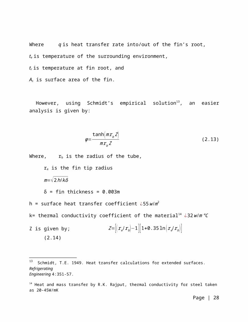
However, using Schmidt’s empirical solution13, an easier analysis is given by:
ϕ=tanh (mr b Z )
mrb Z(2.13)
Where,rb is the radius of the tube,
re is the fin tip radius
m=√2 h/kδ
δ = fin thickness = 0.003m
h = surface heat transfer coefficient ¿55 w /m2
k= thermal conductivity coefficient of the material14 ¿32 w /m℃
Z is given by; Z=[ (r e/rb )−1 ] [1+0.35 ln (re /rb ) ] (2.14)
Therefore, from the available materials, the fins efficiency was calculated by substituting the actual parameters as shown below;
Z=[ (0.04 /0.025 )−1 ] [1+0.35 ln (0.04 /0.025 ) ]=0.6987
m=√ 2× 5532× 0.003
=33.85
And therefore,
ϕ=tanh (33.85× 0.025 ×0.6987 )
33.85 × 0.025× 0.6987=0.897
Therefore, using the designed fins of outer an outer diameter of 80mm, the fins would achieve an efficiency of up to 89.7%.
13 Schmidt, T.E. 1949. Heat transfer calculations for extended surfaces. RefrigeratingEngineering 4:351-57.
14 Heat and mass transfer by R.K. Rajput, thermal conductivity for steel taken as 20-45W/mK
Page | 21

2.5.2 Flywheel size calculation
The flywheel was incorporated to store the momentum generated by the engine. Thus, the flywheel mass had to be sizable enough to achieve this. The following is some simple calculation that aided in estimating the desired size.
Power output desired was 45 watts. Thus the flywheel needed to store this energy and allow smooth rotation of the piston in the cylinder.
Energy stored by a flywheel=12
× I ×ω2(2.15)
Where I , second moment of Inertia=12
× Mass × Radius2
ω ,rotation per minute ,=184 rpm as calculated by the Baele equation
Therefore, making the mass, M, the subject of the formula and solving,
Mass × Radius2=4 × Energy stored
ω2
¿ 4 × 45
1842=5. 32× 10−3 kgm2
Therefore, from the available material of 6mm thickness, a flywheel of 0.13m in diameter of mild steel was selected. The flywheel had a mass of 0.6kg.
2.6 Solar Energy
2.6.1 The sun
The sun continually irradiates the earth at a rate of about 1.74 x 10¹⁴ kW. If we imagine this energy to be distributed over a circular disk with the earth's diameter, the solar radiation is about 1367W/M2 as measured by satellites abode the atmosphere.
The temperature of the sun varies from tens of millions of Kelvins in its core to between 4000 & 6000K at its surface where most of the sun’s thermal radiation originates.
Page | 22

The wavelength distribution of the suns energy is not quite that of a black body, but it may be approximated as such.15
Energy from the sun is distributed as shown in the diagram below:
Figure 2 . 9 : Distribution of solar energy on earth
The figure shows what becomes of the solar energy that impinges on the earth if we average it over the year and the globe taking into account of all the kinds of weather.
Only about 45% of the suns energy reaches the earth’s surface. The mean energy received is about 235W/M2 if averaged over the surface and the year.
Solar radiation reaching the earth’s surface includes direct radiation that has passed through the atmosphere and diffuse radiation that has been scattered but not absorbed by the atmosphere.
2.6.2 Harnessing the solar energy
For solar heating, we incorporated a parabolic solar concentrator that could be attached to the Stirling engine if need arose.
A solar concentrator is a device that optically reflects and focuses incident solar energy onto a small receiving area. As a result of this concentration, the intensity of the solar energy is magnified, and the temperatures that can be achieved at the receiver (called the "target") can approach several hundred or even several thousand degrees Celsius. The concentrators must
15 Leinhard IV, J. H. (2004). A heat Transfer Text book 3rd Edition. Chapter 10.6
Page | 23

move to track the sun if they are to perform effectively. Our concentrator in this case was a parabolic mirror, same one that is used for solar cookers as shown in the figure below;
.Figure 2 . 10 : Examples of parabolic reflectors
When a three dimensional parabola (i.e. a paraboloid) is aimed at the sun, all the light that falls upon its mirrored surface is reflected to a point known as the focus. If a black cooking pot is placed at the focus it will absorb the light’s energy and become very hot.
A satellite dish is an example of a paraboloid that can be made into a cooker. Parabolic Solar cookers heat up quickly and are used like a standard stovetop range to sauté or fry foods, boil water, or even bake bread. They can also be used to generate steam, power Stirling engines, crack water to produce H2 gas, and even plasma matter. It is easy to see in today’s world that this shape is successful in its use.The detachable concentrator will be as shown below:
Figure 2 . 11 : The side and front views of the Stirling engine being heated via solar
To increase the intensity of the sun, we thought it would be a great idea to include a lens in the concentrating unit as an option. The focal point of the concentrator has to be calculated in order to know how far the displacer should be from the concentratorExample of a calculation; if a parabolic mirror is 20 cm across at its edge and is 6 cm deep,
Page | 24

Drawing the parabola used to form the dish on a rectangular coordinate system so that the vertex of the parabola is at the origin and its focus is on the positive y-axis. i.e.
The form of the equation of the parabola is x2 4ay = and its focus is at (0, a).Since (10, 6) is a point on the graph, the equation is
102=4a (6)100=24a
Therefore, a =100/24 =4.17cm
The heat source will be 4.17cm from the center vertex of the dish in direct line of sight toward the sun.
2.6.3 Solar concentrator efficiency
The efficiency of the solar receiver providing a heat source of TH = 700K and a heat sink at temperature To = 300K can be estimated as;
η=ηReceiver−ηCarnot
Where, ηCarnot=1− T o
T H
And, ηReceiver=QAbsorbed−Qlost
Qsolar
WhereQsolar,QAbsorbed,Qlost are respectively the incoming solar flux and the fluxes absorbed and lost by the system solar receiver.
For a solar flux I=1367W/m2 concentrated 10 times with an efficiency ηOptics on the system receiver and lost by the solar receive.
Qsolar=ηOptics ICA (2.16)
Page | 25

QAbsorbed=α Qsolar (2.17)
For simplicity, assuming losses by radiation only, for a radiating area A, and emissivity, applying the Stefan-Boltzmann law yields:
Qsolar=Aϵσ T H4 (2.18)
Substituting these equations to the overall efficiency equation and assuming perfect optics for simplicity (ηOptics=1)
η=(α−σϵ T H
4
IC )(1− T o
T H) (2.19)
η=(0.15−5.67×10−8× 0.05× 7004
1367 ×10 )(1−300700 )
η=5.7 %
3 CHAPTER THREE: DESIGN AND FABRICATION
3.1 DESIGN
3.1.1 INTRODUCTION
The Gamma configuration was used in design, with a separate chamber for the displacer, for ease in fabrication. The heating chamber was given a special design to facilitate heating using both an open flame as well as solar heat. The solar concentrator was then designed to be detachable, for use as hybrid.
To ensure the model as cost effective as possible, we made most dimensions that would enable fabrication from scrap metal.
3.1.2 DESIGN PROCESS
Initial designs
The design process was started off with simple hand sketches that were then drawn using CAD tools. The first sketches, shown in Fig 3.1, were drawn using the Rhinoceros Software. These
Page | 26

preliminary sketches were too simple and did not consider machine dynamics that had to be taken into account. These sketches, however, were the first step towards project actualization.
Figure 3 . 12 : Stirling engine designs drawn using the Rhinoceros Software
First revision designs
Page | 27

The revised designs, drawn on the Autodesk Inventor software, were better in kinematics and gave the best simulation on a computer. This design, shown in Fig 3.2 was the closest to finally getting the Stirling engine final design.
It is noted here that this first revision of the design was not used because the connectors used in design would be too hard to fabricate. Further, the heating portion had to be changed in design to counter overheating of the system.
Figure 3 . 13 : First revision of the Stirling engine drawn using Autodesk Inventor
Second revision - Final designs
After the final adjustments, the final design shown in Fig. 3.3 was drawn using Autodesk Inventor. The revisions made included a new heating chamber that made it easy to heat using an open flame.
Figure 3 . 14 : The Final Stirling Engine Design used in fabrication
Page | 28

3.1.3 THE DESIGN MANUAL
See attached copy of the design manual used in fabrication - Appendix A
3.2 FABRICATION
3.2.1 INTRODUCTION
Most of the project’s parts were fabricated in the University’s Mechanical Engineering workshop. It was however noted that some high precision parts such as the piston cylinder couldn’t be machined in the workshop. This is because the machines available were old and because of this, the work pieces are prone to vibrations during machining which is not ideal for high precision parts especially due to the finishing.
For this reason, these high precision parts were taken to engine block specialists in Nairobi’s Kirinyaga Road for machining. In addition, the piston was bought as a complete piece. Finally, the base board was machined at the University of Nairobi FABLAB. Using the ShopBot, a CNC machine, the piece of wood was cut to precision, and then some writing etched using the LASER cutting machine.
In total, it took us about seven weeks to fabricate from start to completion. A further three weeks were consumed in testing the engine’s performance.
The fabrication was done by close assistance and supervision of technicians at the workshop, whose invaluable help we enjoyed and appreciated.
3.2.2 Project planning
The following is a summary of the planning of the project, from its inception to completion
PROJECT STAGES
TIME TAKEN TO COMPLETE (IN WEEKS)
1 2 3 4 5 6 7 8 9 10
11
12
13
14
15
16
17
18
19
20
RESEARCHDESIGNMATERIAL & FUND AQUISITONFABRICATION & ASSEMBLYTESTINGDOCUMENTATION
Table 3 . 1 : SCHEDULE OF OPERATIONS
Page | 29

In the initial stages of this project, 6 weeks were used for research of the project. The research included gathering information from books (see ref) about Stirling engines, their history, and theory and also made investigations about solar energy.
The 2nd stage of the project was initialized 2 weeks after after the research of the project was initialized. This stage included reviewing of old designs and making preliminary sketches. From this review, it was decided that the gamma configuration was best suited for our design & to test the viability of the solar energy. In addition, it was simple to fabricate and its design could easily accommodate the solar concentrator proposed.
The 3rd stage of the project was initialized in the 13 th week and it involved deciding what materials to use from what was readily available. During this same period, the designs were taken for approval and request for funding made.
The 4th stage involved fabrication & assembly, which took 8 weeks to complete. This fabrication took place at the University of Nairobi Mechanical Engineering workshops, the UoN FabLab and also outsourcing some of the work to specialists in Engine servicing.
In the 5th stage, testing started immediately after the fabrication of the parts was completed. From the tests, minor adjustments continually took place and more tests were carried out for a period of 2 weeks.
The documentation of this project was carried out throughout, from its inception to completion.
3.2.3 Parts fabrication and assembly
The table below shows a brief description of the fabrication process for each part.
Part No.
Part Name Fabrication process involved
1.
Bearing plate
-Chain Drilling & Filing -Drilling
2.
Crank shaft
-Turning-Drilling
3.
Crank web
-Cutting Profile On Lathe Machine-Drilling Using Dia 8mm For Pin Holes
Page | 30
4.
Cylinder plate
-Cutting-Filing-Drilling
5.
Displacer cylinder (heat sink)
-The cylindrical section cut from a pipe of internal diameter 54mm to a length of 100mm-The fins cut using a lathe machine from a thin plate of thickness 3mm-The end plates machine using a lathe machine from a plate of thickness 4.5mm, then drilled using an 8mm drill bit
6.
Displacer cylinder (heater)
The cylinder cut from a pipe of internal diameter of 54mm, then sealed off on one side by a plate of similar thickness by brazing-The end plate made from a 4.5mm thick plate
7.
Displacer rod
Aluminium Rod of diameter 6mm machined from a lathe machine
8.
Displacer
Wooden block machined on a lathe machine to diameter 30mm and length 80mm
9.
Flywheel bush
Mild steel rod Machined on a lathe to 6mm diameter
10.
Flywheel
Cut from a 4.5mm thick plate to 150mm diameter
11.
Guide bush
Mild steel rod turned on both ends to 24 and 12mm and drilled through using 6mm drill bit
12.
Lever connecting rod
Cut off from a 3mm mild steel plate and drilled using a 6mm drill bit
Page | 31

13.
Levers 2 off
Cut off from a 3mm mild steel plate and drilled using a 6mm drill bit
14.
Links 2 off
Cut off from a 3mm mild steel plate and drilled using a 6mm drill bit
15.
Power cylinder
-Power cylinder machined from cast iron.-Bored to diameter 40mm(internal) and horned for smooth surface on the inside to allow piston to move freely without much friction-end plate made from 4.5mm thick plate and welded to the cast iron cylinder
16. Base plate Machined from a wooden base of 320 X 140 mm dimension17. Piston Motor cycle piston of diameter 40mm acquired with oil rings
TABLE 3 . 2 : OPERATION CHART
3.3 Assembly The following are the parts in before and after assembly
1. Bearing plate:
The bearing plate was cut from a 3.5 mm mild steel plate. This was the strongest plate available for use as it would be rigid enough to support the fly wheel and crank web. An angle beam was arc welded to its bottom to make fitting to the base more easily via bolting.
2. The
Cylinder heater:
The cylinder heater was made form a 52mm diameter pipe of length 100mm. The end of the pipe was sealed off by brazing a 3mm plate onto its end. The other ends, the flanges, were made from a 3.5mm plate that had been shaped from a 4.5mm plate and welded onto the pipe cutoff.
Page | 32

3. The cylinder heat sink:
The main body of the cylinder heat sink was also made from the 52 mm pipe cut to 100mm.
The cooling fins were cut from a 3mm thick sheet metal using a lathe and were brazed onto the pipe. The flanges were made from a 3.5mm mild steel plate and arc welded to each end. An 8mm drill was used to make holes for bolting.
4. The cylinder plate
The cylinder plate was cut from a 3.5mm mild steel plate and drilled using 8mm bit for fastening holes. An angle beam was welded onto it for easier fastening onto the base.
Page | 33

5. The displacer guide bush
The guide bush was made by turning a one inch mild steel rod on a lathe machine to diameters 24 & 12 mm and to a length 62mm. its finishing was done using an emery cloth.
6. The dispalcer:
The displacer was made from a piece of light wood that was turned on a lathe machine do a diameter of 30mm and a length of 80mm. it would be then threaded to accommodate the displacer rod.
7. The power cylinder
The power cylinder was made purely of cast iron. This was a high precison part and couldn’t be machined on the workshops lathe machines because of vibrations. Outsourcing this pieces was the best option. The initial dimensions of the sleeve were 20mm internal diameter and 180mm length. The sleeve was machines to 40mm internal diameter and horned on the inside to accommodate the power piston.
Before machining:
Page | 34

After machining;
8. The power piston:
The power piston was a high precision part and therefore machining would be difficult. Buying a piston of a 50cc motorcycle piston complete with its oil rings seemed to be a better option. The piston was of 40mm diameter.
9. The fly wheel assembly;
The fly wheel was cut from a 4.5mm thick steel plate. To make fitting onto the bearing easier, the power pin was force fitted onto the fly wheel.
10. The connecting rod;
The connecting rod was machined from a one inch rod to a diameter of 6mm and a length of 150mm. The flat edge was machined on an end miller and a hole of diameter 6mm made on the face so as to accommodate the gudgeon pin.
Page | 35

11. The engine base:
The base of the engine was machined from a piece of 30mm thick board. The board was cut using the Shop Bot, a CNC cutting machine, because it was faster and more accurate. The engraving on the board was made using a CNC laser cutter.
12. The bearing plate assembly;
The fly wheel, crank web and bearing plate were connected using an 12mm pin. On the fly wheel, a steel rod was machined to support its upright position on the bearing plate.
Page | 36

13. The complete engine assembly:
The cylinder heater, cylinder heat sink and power cylinder were fastened to the cylinder plate by M8 bolts. To seal off the joint, gaskets were cut and silicon applied onto the surfaces before the fasteners were tightly put.
The lever con rods and other small levers were rivetted onto each other and the bearing plate with ample clearance to facilitate movement between joints.
Finishing of most of these parts was done by using differnent grades of emery cloth.
To support the base, rubber stands were fitted onto the base.
Figure 3 . 15 : Showing The Parts Before And After Assembly
Page | 37

4 CHAPTER FOUR: FINDINGS AND DISCUSSION
4.1 TESTS RESULTS
4.1.1 TEST 1
After the first test was conducted, by heating using oxyacetylene flame and cooling by ambient air, massive air leakages were discovered from the power cylinder assembly.
This was because piston rings had not been fitted on the piston during assembly. It is however noted that the piston rings omission was intentional to make the engine smooth running with as little friction as possible in the power cylinder.
4.1.2 TEST 2
Before the second test, the piston rings were fitted on the piston and adequate lubrication put in the power cylinder and other moving parts to reduce friction.
It was noted that after fitting the piston rings the engine became too stiff and therefore need to make it as free running as possible. To achieve this, the assembled engine was run on a lathe by clamping the flywheel to the lathe jaw and running at varying speeds.
In the second test, it was discovered that there was reduced air leak in the power cylinder. Further, due to increased pressure in the power cylinder, air leaks were discovered from the gaskets.
4.1.3 TEST 3
Before the third test, the engine was disassembled and new gaskets used between the flanges and fresh sealant (silicone) used to curb the new found leaks.
In the third test, the engine developed signs of kicking power, but due to more air loss during compression stroke in the power cylinder, the engine experienced power loss and could not run.
Upon scrutinizing the engine for the air loss, it was discovered that the engine was losing power due to small air leaks from the power cylinder due to irregularity in the cylinder profile. This irregularity in profile may have been attributed to any of the following stages in fabrication:
During welding the cylinder to the flanges Imperfect machining when it was fabrication was outsourced In general assembly
The manufacture of the power cylinder was a precision procedure and therefore expensive. Constrained by monetary resources, fabrication was left there and a recommendation for further investment and development was made.
Page | 38

4.2 CALCULATIONS
4.2.1 Engine efficiency
The efficiency of the engine was calculated using the following formula:
Efficiency= Work outputEnergy input
(4.1)
The power input to the system was estimated by taking the temperature difference between the heated part and the heat sink, as follows;
Energy input per second=Mass of air × Air Cp × ∆ T (4.2)
However the mass of air can be calculated as;Mass=Dens ity ( ρ ) ×volume (v )
Therefore, takin ρ=1.2 kg/m3
v=1200 ×10−6m3
Specific heat capacity ,Cp=1005 J /kg K
Temperature change , ∆ T ≈ (600−50 )=550 K
Energy input per second=1.2×1000 × 10−6 ×1005 ×550
¿663 J / s
Taking the power output as that estimated by the Baele equation (eqn 2.11) as;
Power output=45 watts
Therefore, the efficiency can be calculated as;
Actual Efficiency= 45663
×100=7.7 %
Thus the actual efficiency of the engine is 7.7%. This can be compared to the Ideal theoretical Stirling engine efficiency, which is theoretically equal to the Carnot efficiency as;
Ideal theor etical Efficiency=1−Tmin
T max(4.3)
¿(1− 50+273.15600+273.15 )×100=63 %
Page | 39

4.3 DISCUSSION The project was carried out with an objective to explore the possibility of tapping power for subsistence use from a Stirling engine. This was done with the view of aiding the government find alternative sources of energy to for the rural electrification.
To achieve this, a solar powered Hybrid Stirling engine was envisaged as a possible route to explore alternative energy. The hybrid concept was chosen to take advantage locally available biomass source of energy as well as the hot and sunny weather experienced in some of the marginalized parts of Kenya.
With this vision, sketches were made that led to computer aided designs that gave a graphical representation of what was anticipated during and after fabrication.
After designs approval and acquisition for funds and materials, fabrication was carried out in a span of about 8 weeks and a prototype came to being.
Tests were carried out with a view of estimating actual efficiency and calculating power output from the engine. The engine was put through a series of tests that were not conclusive due to air loss. The intension to measure the power output was therefore not feasible. The theoretical efficiency was then used to estimate the net power output using the Baele equation (eqn 2.11) as 45 watts. With this power estimate, the engine efficiency was calculated as 7.7%. This efficiency, compared to the theoretical Stirling engine efficiency of 63%, was found to be more reasonable and practical.
Some of the losses of power, as reflected from the efficiency, were attributed to friction in the engine. In spite of the thorough lubrication that was done, friction was inevitable. From the assessment carried out, the greatest source of friction was in the flywheel assembly. This was because the flywheel assembly constituted several mating pieces, which rubbed on each other during operation. In addition, there was a lot of friction in contact between the piston and power cylinder arrangement.
Further, the engine experienced power loss due to out-of-balance masses in the assembly. It is noted that the attachment of the crank shaft to the flywheel introduced an out of balance mass that contributed to the power loss. To rectify this, a re-examination of the parts in the assembly was recommend, in addition to a kinematic assessment of the engine to ensure all parts were balanced.
In carrying out the project, many challenges were encountered. Top on the list of these was lack of funds to actualize desired results. This was a major problem that saw us not have enough money to get a new power cylinder to further test the engine. It is noted that we had to supplement the allocated Ksh. 5000, with an extra Ksh. 8500 to fabricate the prototype (see bill of quantities- appendix B). Most of the money consuming parts were the high precision ones that required outsourcing services in town.
Page | 40

Another challenge was lack of materials from the Mechanical Engineering workshop store. This further aggravated the lean working budget. Lastly, time constrain was another factor of challenge. This saw us spend long hours in the workshop, and even more time in Nairobi’s Kirinyaga Road, with the burning ambition to actualize the project idea. In spite of all these challenges, we were able to fabricate a prototype that pointed us to the right direction and took the project a step closer to actualization.
4.4 CONCLUSION The project was undertaken to explore the practicality of power production from a Hybrid Stirling engine. This included research, design and fabrication.
The fabricated model was then tested and it was noted that some air leaks existed in the power cylinder. The power cylinder was an expensive part, and constrained by monetary resources, discussions and recommendations were made and the project was wrapped up.
On the overall, the project was successful on several accounts. First, a successful research led to a design that was simulated on Autodesk Inventor, and showed kinematic synchronization. In addition, the prototype was fabricated and pointed the project exploration in the right direction. The setbacks encountered were used to give recommendations and pointed out some ways of project improvement. A theoretical energy assessment showed that with an open flame of sufficient temperature, (about 600oC) the designed Stirling engine would generate 45watts of power.
In conclusion therefore, the project successfully explored the practicality of generating power from a Hybrid Stirling engine.
4.5 RECOMMENDATIONS a) More project funding
Most precision parts demanded large resource allocation. This was because we had to outsource machining services from specialists in town
b) Further research and exploration
Further research and exploration of this technology will realize its full potential. We therefore recommend that students to be encouraged to take this project for research.
c) Government partnership with academia
In order to realize the vision 2030, the government should work closely with academia to look into ways of creating jobs and expand economic space using technology. With regard to the Stirling engine, the government should provide standards and guidelines for further research development of this exciting technology.
Page | 41

d) Design & Fabrication Improvements
Having fabricated the Gamma configuration Stirling Engine, we noted a few areas that needed improvement:
i. The oil in the power cylinder seemed to dry off at a faster rate than we could anticipate. We realized that this was due to a design flaw in that we hadn’t included a means on oiling the chamber when necessary. It was therefore noted that an oil nipple should be introduced on the power cylinder so as to make lubrication of the chamber easier when needed.
ii. There was a lot of “out of balance” movement from the fly wheel which might have caused a lot of vibrations if the engine were running. It is therefore necessary to carry out a kinematic assessment to be able to do a mass balance on the flywheel.
iii. To tap generated power from the engine we propose the attachment of a dynamo to the flywheel and a battery to store the energy realized.
Page | 42

5 REFERENCES
1. B. Kongtragool, S. W. (2003). A review of solar-powered Stirling engines . Renewable and Sustainable Energy Reviews 7, 131–154.
2. Boles, Y. A. (n.d.). Thermodynamics: An Engineering Approach, 5th edition. In Y. A. Boles.
3. Husk Power Systems. (n.d.). Retrieved February 2012, from http://www.huskpowersystems.com
4. Konax Stirling Engines. (n.d.). Retrieved january 2012, from Konax Stirling Engines: http://www.kontax.co.uk/docs/history.pdf
5. Leinhard IV, J. H. (2004). A heat Transfer Text book 3rd Edition. Phlogiston Press.
6. McCONKEY, T. E. (2009). Applied Thermodynamics. In T. E. McCONKEY, Applied Thermodynamics for engineering technologists (pp. Chapter 5: Heat Engine Cycle, 163-165).
7. Ministry of State for Planning, N. D. (n.d.). Vision 2030. Retrieved January 2012, from Vision 2030: http://www.vision2030online.go.ke/
8. Rajput, R. K. (2006). HEAT AND MASS TRANSFER. S.CHAND.
9. Schmidt, T. (1949.). Heat transfer calculations for extended surfaces. Refrigerating Engineering
10. Stirling Engines. (n.d.). Retrieved January 2012, from Wikipedia: http://en.wikipedia.org/wiki/Stirling_engine
Page | 43

APPENDIX A: STIRLING ENGINE DESIGN MANUAL
Page | 44

APPENDIX B BILL OF QUANTITIES
PART MATERIAL DIMENSIONS (MM) QTY COST1 Base Wood 300mm by 200mm 1 -2 Base support Rubber 4 5003 Plate 1 Mild steel 2sq feet, 3mm thick 1 5004 Plate 2 Mild steel 2sq feet, 2mm thick 1 5005 Displacer Cylinder Mild steel Dia=52mm pipe;
L=500mm1 500
6 Displacer Wood L=75mm; Dia=40mm 1 -7 Silicon sealant 1 7008 Nuts, bolts and rivets M8 20 6009 Fly Wheel plate Mild steel 1sq feet, 6mm thick 1 50010 Insulation Air and oil
Gasket2sq feet Sheet 1 700
11 Flywheel support rod and bush
Mild steel 3” 2 foot Rod 1 1000
12 Power con Rod Mild steel 2” 1 foot Rod 1 500
13 Power Cylinder (inclusive of machining)
Cast iron 40mm internal diameter 1 4,000
14 Power Piston and oil rings (for 50cc Motor bike)
Aluminum 40mm diameter 1 2,500
15 Miscellaneous 1,000
Total Ksh13,500
Page | 45

APPENDIX C ILLUSTRATIONS
Figure 5 . 16 : Stirling Engine Technology being made use of in California
Page | 46