stress–strain relation of cualni sma …users.monash.edu.au/~wyan/papers-pdf/acta2.pdf · axial...
TRANSCRIPT

STRESS±STRAIN RELATION OF CuAlNi SMA SINGLE
CRYSTAL UNDER BIAXIAL LOADINGÐCONSTITUTIVE
MODEL AND EXPERIMENTS
D.-N. FANG1, W. LU1, W.-Y. YAN1, T. INOUE2 and K.-C. HWANG1{1Failure Mechanics Laboratory, Department of Engineering Mechanics, Tsinghua University, Beijing100084, P.R. China and 2Department of Energy Conversion Science, Kyoto University, Yoshida-
Honmachi, Sakyo-ku 606-8501, Kyoto, Japan
(Received 14 August 1998; accepted 22 August 1998)
AbstractÐIn the previous work of two of the authors, a generalized micromechanics constitutive modelwas developed to describe thermoelastic martensitic transformation. In order to verify the theory and to in-vestigate basic properties of thermoelastic martensitic transformation in shape memory alloys (SMA), uni-axial and biaxial loading tests under di�erent combined loads at a constant temperature were performedon cruciform specimens of a SMA CuAlNi single crystal. The crystallographic theory for martensitic trans-formation has been employed to calculate the orientations of martensite variants and the transformationplastic strain. Experimental data were compared with theoretical calculation by the generalized constitutivemodel based on micromechanics. The results show that the constitutive theory can describe the complexthermodynamic processes, such as the forward transformation, reverse transformation and reorientationhappening simultaneously, and the theoretical predictions consist well with experiments. # 1998 ActaMetallurgica Inc. Published by Elsevier Science Ltd. All rights reserved.
1. INTRODUCTION
Martensitic transformation can be induced by the
application of stress as well as by change in tem-
perature. When the shape and volume change pro-
duced by the martensite transformation is
accommodated through elastic deformation, this
transformation is called thermoelastic martensitic
transformation. An important characteristic of
shape memory alloys (SMA) is the ability to
undergo such a di�usionless, structural and revers-
ible thermoelastic matensitic transformation [1].
Detailed investigations on thermoelastic martensitic
transformation have been done in the ®elds of phy-
sics and materials science and a quite complete
theoretical system, which includes the transform-
ation crystallographic theory and thermodynamics
etc., has been established by Wechsler et al. [2],
Wayman [3], Bowles and Mackenzie [4], Delaey et
al. [5], Christian [6], James [7], Ball and James [8],
Bhattacharya [9], Abeyaratne et al. [10, 11], and
many others. With the increasing application of
SMA and structural ceramics, the study on the con-
stitutive relation of the materials with thermoelastic
martensitic transformation attracts interest of the
researchers of solid mechanics and a lot of work
has been done by Falk [12], Patoor et al. [13],
Abeyaratne et al. [10, 11], Muller and Xu [14], Chu
and James [15], Tanaka et al. [16, 17], Liang et
al. [18], Sun and Hwang [19, 20], Fischer et
al. [21, 22], Yan et al. [23±25], Song et al. [26], Chen
et al. [27, 28], Lu and Weng [29] and many others.
In the light of the directions of the process and
the change in material microstructures, thermoelas-
tic martensitic transformation can be divided into
three kinds [5]: the forward transformation (p4 m,
i.e. the transformation from parent phase to mar-
tensite), the reverse transformation (m4 p, i.e. the
transformation from martensite to parent phase)
and the reorientation (m4 m) between di�erent
kinds of martensite habit plane variants. These
changes in microstructures lead to various macro-
scopic phenomena such as pseudoelasticity, shape
memory e�ect, etc. Therefore, in order to under-
stand the transformation constitutive behavior more
clearly, it is necessary to study it in such a ®ner
scale as the scale of variants. In the previous work
(see Sun and Hwang [19, 20], Yan et al. [23±25],
Chen et al. [27, 28]), the constitutive models of
SMA and ceramics were developed under complex
thermomechanical conditions and these theories
were applicable directly (see, for instance, Stam et
al. [30], Chen et al. [27, 28]). However, due to lack
of test data for SMA single crystals subject to
multi-axial loading, the constitutive model for SMA
single crystals has only been compared with the
available experiments under uniaxial loading.
The pseudoelastic phenomena of SMA single
crystals under uniaxial loading have been investi-
gated by many authors, such as Okamoto et al. [31],
Horikawa et al. [32], Shield [33], and many others.
Acta mater. Vol. 47, No. 1, pp. 269±280, 1999# 1998 Acta Metallurgica Inc.
Published by Elsevier Science Ltd. All rights reservedPrinted in Great Britain
1359-6454/99 $19.00+0.00PII: S1359-6454(98)00303-6
{To whom all correspondence should be addressed.
269
Some researchers (for instance, Sittner et al. [34],Tokuda et al. [35]) have experimentally investigated
the constitutive behavior of the TiNi polycrystalsunder combined tension and torsion. Chu andJames [15] did nice work to build biaxial setup for
SMA single crystals, and observed the microstruc-tural changes relative to the hysteresis, evolution oftwins and metastability of SMA, without strain
measurement. For combined tension±torsion testsof anisotropic tubular specimens cut from a singlecrystal rod, there arises di�culty that the strain
®elds are nonuniform in the circumferential direc-tion. The biaxial test has the advantage of keepingthe directions of principal stresses unchanged rela-tive to the material. However, to the best knowl-
edge of the authors, it seems that there have beenno stress±strain tests under biaxial loading on theSMA single crystals. In this investigation, in order
to verify the developed constitutive theory and tounderstand basic properties of thermoelastic mar-tensitic transformation in SMA single crystals, uni-
axial and biaxial loading tests under di�erentcombined loads at a constant temperature were per-formed on cruciform specimens of a SMA CuAlNi
single crystal. The crystallographic theory for mar-tensitic transformation developed by Wechsler etal. [2] has been employed to calculate the orien-tations of martensite variants and the transform-
ation plastic strain. It was shown in Ref. [36] thatthe generalized micromechanics constitutive modelproposed by Yan et al. [23±25] and Song et al. [26]
can predict very well the di�erent tensile curves aswell as the kinds of martensite variants occurring inuniaxial tensile loading along di�erent crystallo-
graphic directions of the CuAlNi SMA single crys-tal. In this paper experimental data of biaxialloading will be compared with theoretical predic-tions based on the same constitutive model. The ex-
perimental results agreed favorably with theoreticalpredictions.The plan of the rest of the paper is as follows.
Section 2 introduces the biaxial setup and the ex-perimental procedure. The experimental results anddiscussions are demonstrated in Section 3. In
Section 4, the results of the orientations and trans-formation plastic strain of 24 martensite variantscalculated by means of the crystallographic theory
for martensitic transformation are presented. Forthe completeness of the paper, in Section 4, the pro-posed micromechanics constitutive model is brie¯yintroduced. The comparison of the theoretical pre-
dictions and experimental data is made in Section5. The conclusions are given in Section 6.
2. EXPERIMENTAL PROCEDURE
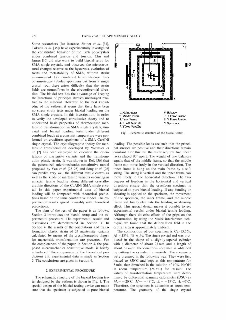
The schematic structure of the biaxial loading tes-ter designed by the authors is shown in Fig. 1. Thespecial design of the biaxial testing device can makesure that the specimen is subjected to pure biaxial
loading. The possible loads are such that the princi-pal stresses are positive and their directions remain
constant. For this test the tester requires two linearjacks placed 908 apart. The weight of two balances
equals that of the middle frame, so that the middleframe can move freely in the vertical direction. The
inner frame is hung on the main frame by a softstring. The string is vertical and the inner frame canmove freely in the horizontal direction. The two
degrees of freedom in the horizontal and verticaldirections ensure that the cruciform specimen is
subjected to pure biaxial loading. If any bending orshearing is applied to the specimen, the movement
of the specimen, the inner frame, and the middleframe will ®nally eliminate the bending or shearing
e�ect. This special design makes it possible to getexperimental results under biaxial tensile loading.
Although there do exist e�ects of the grips on thedeformation, by using the Moire interference tech-
nique, we found that the deformation ®eld in thecentral area is approximately uniform.
The composition of our specimen is Cu±13.7%,Al±4.18%, Ni±wt%. The single crystal rod was pro-
duced in the shape of a slightly-tapered cylinderwith a diameter of about 23 mm and a length of
about 65 mm. The cruciform specimen is obtainedby cutting the cylinder transversely. The specimens
were prepared in the following way. They were ®rstheated to 8508C and kept at this temperature for
5 min, then drenched in the solution of 10% NaOHat room temperature (26.58C) for 30 min. Thevalues of transformation temperature were deter-
mined by di�erential scanning calorimeter (DSC) asMs=ÿ 208C, Mf=ÿ 498C, As=ÿ 198C, Af=08C.Therefore, the specimen is autensitic at room tem-perature. The geometry of the single crystal
Fig. 1. Schematic structure of the biaxial tester.
FANG et al.: SHAPE MEMORY ALLOY270

specimen is shown in Fig. 2(a). The orientations ofthe specimens were detected by the X-ray back
re¯ection Laue method. The orientations of the
loading axes and the normal of the surface of thespecimens relative to the parent phase can be rep-
resented by points in a stereographic projection as
shown in Fig. 2(b). We specify the horizontal load-
ing axis as the x direction, the vertical loading axisas the y direction and the normal of the surface of
the specimen as the z direction. The applied loads
in two directions were measured by the load cells.The stress distribution (sx, sy) in the test section of
the cruciform specimen is di�erent from the applied
nominal stresses (sx, sy), which are obtainedthrough dividing the two applied loads in x and y
directions by the corresponding cross-sectional area
of the arm of the cruciform specimen. There havebeen great e�orts (e.g. [37, 38]), such as presenting a
series of limbs separated by slots, extending from
each edge of a uniformly thinned square-shapedcentral region and optimizing the geometry of the
cruciform specimen, aiming at homogeneity of the
stress state (sx, sy) in the test region and at thesame time sx1sx and sy1sy, at least for elastic case.
For the specimen geometry shown in Fig. 2(a),
®nite element calculations show that in an isotropicelastic case (Poisson's ratio n = 0.3) there is a
region of size of about 6 mm at least at the test sec-tion where the stress state (sx, sy) is rather uniformwith the error of 5% and the values of the stress(sx, sy) are related to the nominal stress (sx, sy) bythe relation:
sx � 0:8908sx ÿ 0:1616sy
sy � ÿ0:1616sx � 0:8908sy: �1�We have tried both comparing sx±ex curves asshown in Fig. 3 and comparing the theoretically
predicted and the measured sx±ex curves as shownin Figs 7 and 8. We will show the experimentalresults in the former set of data in Section 3 andthe comparison of theoretical calculation and exper-
iment in the latter set of data in Section 5. Wefound that both ways of comparing lead to all thesame conclusions about agreement of theoretical
predictions and experiment. This is why we avoidedthe di�cult task of analyzing the stress distributionin the test region of the cruciform specimen with
accompanying martensite transformation.The overall strains in the x and y directions were
measured simultaneously by two metal foil strain
gages bounded to the specimen. One is to measurethe strain in the x direction and the other in the ydirection. The strain gages were attached to the spe-cimen with a special glue and by means of a special
heat treatment, which can make sure that the straingages can measure large strain accurately up to12% in elongation. Two types of loading programs
are used in our experiments. Figure 4(a) shows theloading path A: y loading 4x loading 4y unload-ing 4x unloading, and Fig. 4(b) illustrates the
loading path B: x loading 4y loading 4x unload-ing 4y unloading.
3. EXPERIMENTAL RESULTS
The measured stress±strain curves in x directionsubjected to several prescribed constant preloadings
in y direction are shown in Fig. 3. A hysteresis loopof the stress±strain curve appears during loading
Fig. 2. (a) Geometry of the ¯at cruciform specimen. (b)Loading directions shown using a stereographic projection.The x direction is the horizontal loading axis, the y direc-tion is the vertical loading axis and the z direction is the
normal of the specimen.
Fig. 3. Measured stress±strain curves at di�erent values ofsy under biaxial loading.
FANG et al.: SHAPE MEMORY ALLOY 271

and unloading processes. The area surrounded by
the hysteresis loop represents the dissipated strain
energy, and the area below the unloading curve cor-
responds to the recoverable strain energy. One of
the main purposes of our experiments is to ®gure
out how signi®cantly the preload imposed in the y
direction in¯uences the stress±strain curves in the x
direction. The loading process is speci®ed as: a ten-
sile preload is ®rstly applied in the y direction of
the cruciform specimen until it reaches a designated
value, and then it keeps constant. Furthermore, atensile load is applied in the x direction. We
recorded the stress±strain curves in the x direction
at di�erent values of sy (=0, 40, 80, 120, 160, 200
MPa). It can be found that the transformation
stresses at which the transformation starts are
increased as the values of load sy are increased.
When sy is zero, the loading is uniaxial. When sy is
not too high, the shape of the stress±strain curves
has no substantial change relative to the stress±
strain curve of uniaxial loading, except that there is
an elastic contraction before loading in the x direc-
tion. The curves are mainly linear below the trans-
formation stress. The curve shows a clear plateau atthe transformation stress. This is due to the trans-
formation from autensite to matensite. When thestress induced martensitic transformation ®nishes,
the slope of the curve begins to increase again.However, when sy is high enough, the shape of thecurve changes signi®cantly, as shown in Fig. 3. It is
found that ex has very high initial values aboutÿ6% before the stress in the x direction is applied.This is because the high preload in the y direction
has caused phase transition before the load in the xdirection is applied. Then, if we apply a load in thex direction, a small load can lead to a plateau due
to reorientation of martensite variants. A second¯at plateau appears when sx reaches another criticalvalue. It is important to point out that the trans-formation mechanism in the case of applying a low
sy is quite di�erent from that in the case of applyinga high sy. In the case of a low sy, only one ¯at pla-teau is caused by the forward and reverse matensite
transformations, while both of two ¯at plateaus inthe case of a high sy are caused by the reorientationamong martensite variants. From Fig. 3 we can
also ®nd that the deformation is anisotropicbecause the transformation stress in the y directionis much higher than that in the x direction under
uniaxial loading. For example, when sy=0, thevalue of stress sx at start of transformation underuniaxial tension in the x-direction equals 102 MPa.When sy=120 MPa, there is no martensitic trans-
formation in the y direction, but the transformationappears when sy=160 MPa. This means that thevalue of uniaxial tension loading sy at start of trans-
formation is larger than 120 MPa but less than 160MPa and is not equal to the value of uniaxial ten-sion loading sx at start of transformation.
4. MICROSCOPIC TRANSFORMATION INDUCEDSTRAIN
In the proposed micromechanics constitutive
model, the microscopic transformation plastic strainhas to be calculated at ®rst. By use of the crystallo-graphic theory for martensitic transformation devel-oped by Wechsler et al. [2] and Bowles and
Mackenzie [4], and in terms of the measured latticevalues of CuAlNi, the habit planes of the 24 var-iants and the transformation induced strains for the
24 variants can be predicted by calculation.According to the crystallographic theory, the mar-tensitic transformation is realized through an invar-
iant plane strain, which is a terminology ofmaterials science and is actually a kind of defor-mation gradient tensor in the light of continuum
mechanics. As shown in Fig. 5, the invariant planestrain (i.e. deformation gradient tensor) D can beexpressed by
D � I� gen �2�where I is the identity tensor of rank two, e is theunit vector along displacement direction of theinvariant plane, n is the unit vector normal to the
Fig. 4. (a) Stress path for loading path A with loadingorder: y loading4 x loading4 y unloading4 x unload-ing; (b) stress path for loading path B with loading order:
x loading4 y loading4 x unloading4 y unloading.
FANG et al.: SHAPE MEMORY ALLOY272
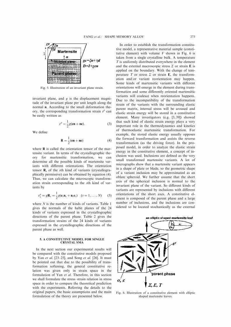
invariant plane, and g is the displacement magni-tude of the invariant plane per unit length along thenormal n. According to the small deformation the-ory, the corresponding transformation strain ep can
be easily written as
ep � 1
2g�en� ne�: �3�
We de®ne
R � 1
2�en� ne� �4�
where R is called the orientation tensor of the mar-tensite variant. In terms of the crystallographic the-
ory for martensitic transformation, we candetermine all the possible kinds of martensite var-iants with di�erent orientations. The orientation
tensor Rs of the sth kind of variants (crystallogra-phically permissive) can be obtained by equation (4).Thus, we can calculate the microscopic transform-
ation strain corresponding to the sth kind of var-iants by
eps � gRs � 1
2g�esns � nses� �s � 1; . . . ;N� �5�
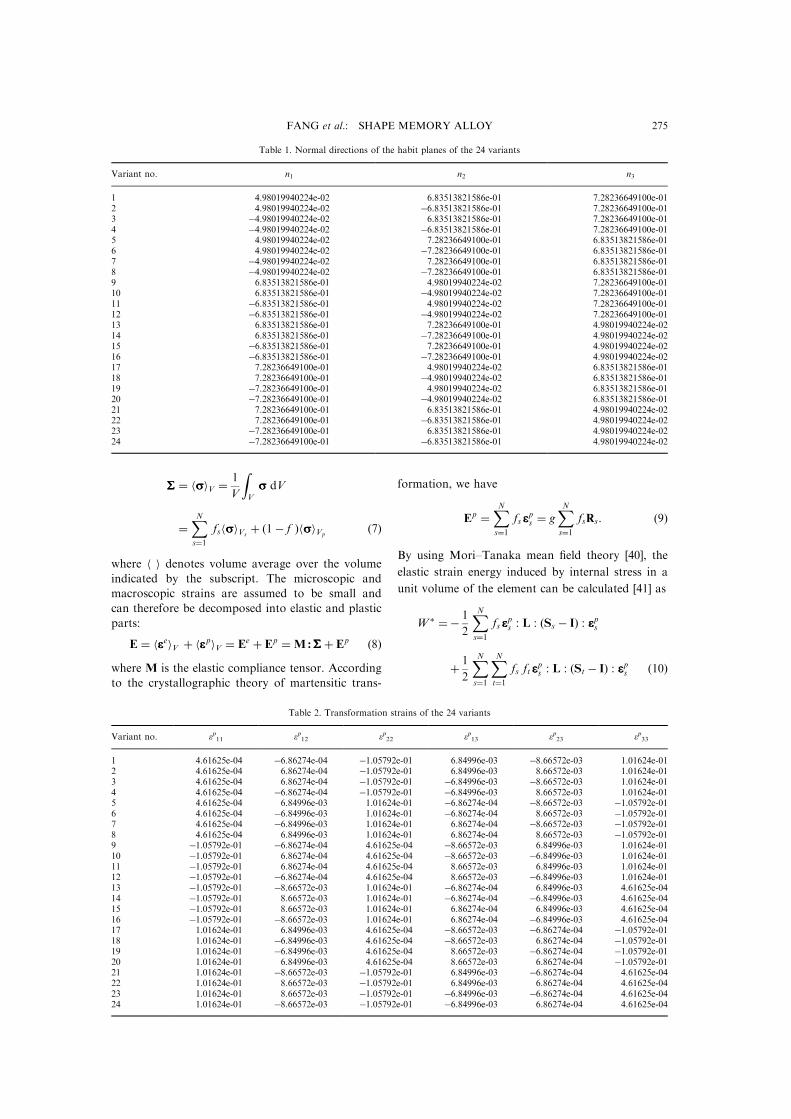
where N is the number of kinds of variants. Table 1gives the normals of the habit planes of the 24
kinds of variants expressed in the crystallographicdirections of the parent phase. Table 2 gives thetransformation strains of the 24 kinds of variantsexpressed in the crystallographic directions of the
parent phase as well.
5. A CONSTITUTIVE MODEL FOR SINGLECRYSTAL SMA
In the next section our experimental results willbe compared with the constitutive models proposed
by Yan et al. [23±25], and Song et al. [26]. It mustbe pointed out that due to the possibility of trans-formation softening, the general constitutive re-
lation was given only in strain space in theformulation of Yan et al. Therefore, in this sectionwe shall formulate the stress±strain relation in stress
space in order to compare the theoretical predictionwith the experiments. Referring the details to theoriginal papers, the basic assumptions and the mainformulation of the theory are presented below.
In order to establish the transformation constitu-
tive model, a representative material sample (consti-tutive element) with volume V shown in Fig. 6 is
taken from a single crystalline bulk. A temperature
T is uniformly distributed everywhere in the elementand the external macroscopic stress S or strain E is
applied on the boundary. With the change of tem-perature T or stress S or strain E, the transform-
ation and/or variant reorientation may happen.
Some kinds of martensitic variants with di�erentorientations will emerge in the element during trans-
formation and some di�erently oriented martensitic
variants will coalesce when reorientation happens.Due to the incompatibility of the transformation
strain of the variants with the surrounding elasticparent matrix, internal stress will be aroused and
elastic strain energy will be stored in a constitutive
element. Many investigators (e.g. [3, 39]) showedthat such kind of elastic strain energy plays a very
important role in the thermodynamics and kineticsof thermoelastic martensitic transformation. For
example, the stored elastic energy usually opposes
the forward transformation and assists the reversetransformation (as the driving force). In the pro-
posed model, in order to analyze the elastic strain
energy in the constitutive element, a concept of in-clusion was used. Inclusions are de®ned as the very
small transformed martensite variants. A lot ofmicrographs show that a martensite variant appears
in a shape of plate or blade, so the geometric shape
of a variant inclusion may be approximated as anoblate spheroid. We further assume that the short
axis of the spherical inclusion is normal to theinvariant plane of the variant. So di�erent kinds of
variants are represented by inclusions with di�erent
orientations of the short axes. A constitutive el-ement is composed of the parent phase and a large
number of inclusions, and the inclusions are con-
sidered to be located stochastically as the external
Fig. 5. Illustration of an invariant plane strain.
Fig. 6. Illustration of a constitutive element with ellipticshaped martensite leaves.
FANG et al.: SHAPE MEMORY ALLOY 273
stress or strain is homogeneous. Therefore, the for-
ward transformation is just the process in which the
number of inclusions or the total volume fraction
of all various N kinds of inclusions increase con-
tinuously, while the reverse transformation is the
process with the number of inclusions decreasing
and the reorientation is the process with the change
of volume fractions between di�erent kinds of var-
iants.
Denote the volume occupied by the sth kind of
variants (s= 1, . . . ,N) by Vs, and the corresponding
volume fraction by fs(=Vs/V). The total volume of
transformed variants Vi, total volume fraction f and
the volume of the parent phase Vp are:
Vi �XNs�1
Vs f �XNs�1
fs Vp � Vÿ Vi : �6�
Under the applied global macroscopic stress S and
temperature T, the microscopic stress and strain in
the element are expressed by ss and ee. Then there
exists the relation between ss and SS,
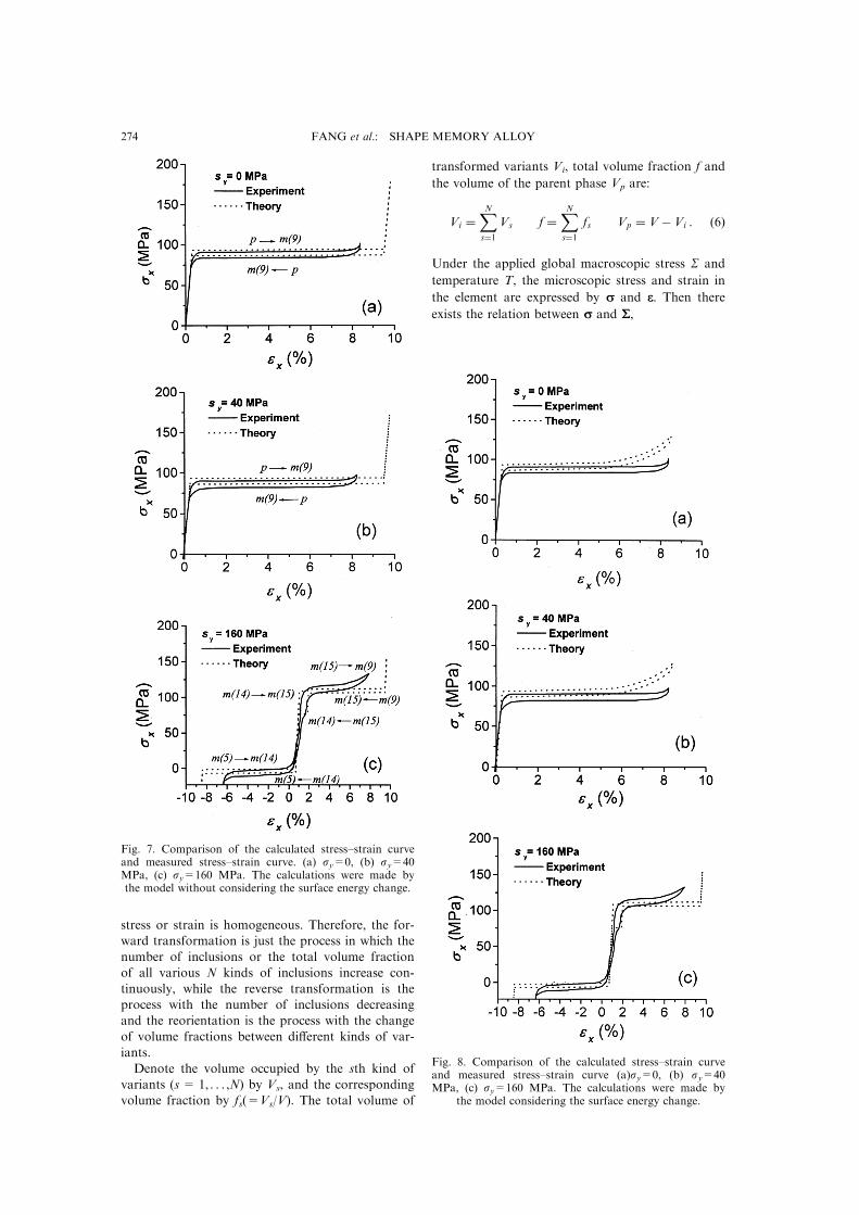
Fig. 7. Comparison of the calculated stress±strain curveand measured stress±strain curve. (a) sy=0, (b) sy=40MPa, (c) sy=160 MPa. The calculations were made bythe model without considering the surface energy change.
Fig. 8. Comparison of the calculated stress±strain curveand measured stress±strain curve (a)sy=0, (b) sy=40MPa, (c) sy=160 MPa. The calculations were made by
the model considering the surface energy change.
FANG et al.: SHAPE MEMORY ALLOY274
SSS � hsssiV �1
V
ZV
sss dV
�XNs�1
fshsssiVs� �1ÿ f �hsssiVp
�7�
where h i denotes volume average over the volume
indicated by the subscript. The microscopic and
macroscopic strains are assumed to be small and
can therefore be decomposed into elastic and plastic
parts:
E � heeeeiV � heeepiV � Ee � Ep �M:SSS� Ep �8�where M is the elastic compliance tensor. According
to the crystallographic theory of martensitic trans-
formation, we have
Ep �XNs�1
fs eeeps � gXNs�1
fsRs: �9�
By using Mori±Tanaka mean ®eld theory [40], the
elastic strain energy induced by internal stress in a
unit volume of the element can be calculated [41] as
W � � ÿ 1
2
XNs�1
fs eeeps : L : �Ss ÿ I� : eeeps
� 1
2
XNs�1
XNt�1
fs ft eeeps : L : �St ÿ I� : eeeps �10�
Table 1. Normal directions of the habit planes of the 24 variants
Variant no. n1 n2 n3
1 4.98019940224e-02 6.83513821586e-01 7.28236649100e-012 4.98019940224e-02 ÿ6.83513821586e-01 7.28236649100e-013 ÿ4.98019940224e-02 6.83513821586e-01 7.28236649100e-014 ÿ4.98019940224e-02 ÿ6.83513821586e-01 7.28236649100e-015 4.98019940224e-02 7.28236649100e-01 6.83513821586e-016 4.98019940224e-02 ÿ7.28236649100e-01 6.83513821586e-017 ÿ4.98019940224e-02 7.28236649100e-01 6.83513821586e-018 ÿ4.98019940224e-02 ÿ7.28236649100e-01 6.83513821586e-019 6.83513821586e-01 4.98019940224e-02 7.28236649100e-0110 6.83513821586e-01 ÿ4.98019940224e-02 7.28236649100e-0111 ÿ6.83513821586e-01 4.98019940224e-02 7.28236649100e-0112 ÿ6.83513821586e-01 ÿ4.98019940224e-02 7.28236649100e-0113 6.83513821586e-01 7.28236649100e-01 4.98019940224e-0214 6.83513821586e-01 ÿ7.28236649100e-01 4.98019940224e-0215 ÿ6.83513821586e-01 7.28236649100e-01 4.98019940224e-0216 ÿ6.83513821586e-01 ÿ7.28236649100e-01 4.98019940224e-0217 7.28236649100e-01 4.98019940224e-02 6.83513821586e-0118 7.28236649100e-01 ÿ4.98019940224e-02 6.83513821586e-0119 ÿ7.28236649100e-01 4.98019940224e-02 6.83513821586e-0120 ÿ7.28236649100e-01 ÿ4.98019940224e-02 6.83513821586e-0121 7.28236649100e-01 6.83513821586e-01 4.98019940224e-0222 7.28236649100e-01 ÿ6.83513821586e-01 4.98019940224e-0223 ÿ7.28236649100e-01 6.83513821586e-01 4.98019940224e-0224 ÿ7.28236649100e-01 ÿ6.83513821586e-01 4.98019940224e-02
Table 2. Transformation strains of the 24 variants
Variant no. ep11 ep12 ep22 ep13 ep23 ep33
1 4.61625e-04 ÿ6.86274e-04 ÿ1.05792e-01 6.84996e-03 ÿ8.66572e-03 1.01624e-012 4.61625e-04 6.86274e-04 ÿ1.05792e-01 6.84996e-03 8.66572e-03 1.01624e-013 4.61625e-04 6.86274e-04 ÿ1.05792e-01 ÿ6.84996e-03 ÿ8.66572e-03 1.01624e-014 4.61625e-04 ÿ6.86274e-04 ÿ1.05792e-01 ÿ6.84996e-03 8.66572e-03 1.01624e-015 4.61625e-04 6.84996e-03 1.01624e-01 ÿ6.86274e-04 ÿ8.66572e-03 ÿ1.05792e-016 4.61625e-04 ÿ6.84996e-03 1.01624e-01 ÿ6.86274e-04 8.66572e-03 ÿ1.05792e-017 4.61625e-04 ÿ6.84996e-03 1.01624e-01 6.86274e-04 ÿ8.66572e-03 ÿ1.05792e-018 4.61625e-04 6.84996e-03 1.01624e-01 6.86274e-04 8.66572e-03 ÿ1.05792e-019 ÿ1.05792e-01 ÿ6.86274e-04 4.61625e-04 ÿ8.66572e-03 6.84996e-03 1.01624e-0110 ÿ1.05792e-01 6.86274e-04 4.61625e-04 ÿ8.66572e-03 ÿ6.84996e-03 1.01624e-0111 ÿ1.05792e-01 6.86274e-04 4.61625e-04 8.66572e-03 6.84996e-03 1.01624e-0112 ÿ1.05792e-01 ÿ6.86274e-04 4.61625e-04 8.66572e-03 ÿ6.84996e-03 1.01624e-0113 ÿ1.05792e-01 ÿ8.66572e-03 1.01624e-01 ÿ6.86274e-04 6.84996e-03 4.61625e-0414 ÿ1.05792e-01 8.66572e-03 1.01624e-01 ÿ6.86274e-04 ÿ6.84996e-03 4.61625e-0415 ÿ1.05792e-01 8.66572e-03 1.01624e-01 6.86274e-04 6.84996e-03 4.61625e-0416 ÿ1.05792e-01 ÿ8.66572e-03 1.01624e-01 6.86274e-04 ÿ6.84996e-03 4.61625e-0417 1.01624e-01 6.84996e-03 4.61625e-04 ÿ8.66572e-03 ÿ6.86274e-04 ÿ1.05792e-0118 1.01624e-01 ÿ6.84996e-03 4.61625e-04 ÿ8.66572e-03 6.86274e-04 ÿ1.05792e-0119 1.01624e-01 ÿ6.84996e-03 4.61625e-04 8.66572e-03 ÿ6.86274e-04 ÿ1.05792e-0120 1.01624e-01 6.84996e-03 4.61625e-04 8.66572e-03 6.86274e-04 ÿ1.05792e-0121 1.01624e-01 ÿ8.66572e-03 ÿ1.05792e-01 6.84996e-03 ÿ6.86274e-04 4.61625e-0422 1.01624e-01 8.66572e-03 ÿ1.05792e-01 6.84996e-03 6.86274e-04 4.61625e-0423 1.01624e-01 8.66572e-03 ÿ1.05792e-01 ÿ6.84996e-03 ÿ6.86274e-04 4.61625e-0424 1.01624e-01 ÿ8.66572e-03 ÿ1.05792e-01 ÿ6.84996e-03 6.86274e-04 4.61625e-04
FANG et al.: SHAPE MEMORY ALLOY 275
where I is the identity tensor, L is the constant
elastic sti�ness tensor of the element and St is
the Eshelby tensor for tth kind of variant
(t= 1,2, . . . ,N), determined by elastic constants and
the shape parameters. De®ning
Ws � ÿ 1
2eeeps : L : �Ss ÿ I� : eeeps �11�
Wst � ÿ 1
2eeeps : L : �St ÿ I� : eeept �12�
we have
W � �XNs�1
fsWs ÿXNs�1
XNt�1
fs ftWst: �13�
For any two kinds of variants s and t, usually
Wst$Wts (s,t= 1,2, . . . ,N). For convenience in
mathematical treatment, we de®ne a symmetric
matrix as
~Wst � 1
2�Wst �Wts�: �14�
When s= t, we have
Wss �Ws �Wt �s; t � 1; . . . ;N�: �15�
Assume the elastic sti�ness tensor L is isotropic,
then Ws (s= 1,2, . . . ,N) are all equal and can be
denoted by Wi (subscript i for ``inclusion'').
Equation (13) can be rewritten as
W � �Wi
XNs�1
fs ÿXNs�1
XNt�1
fs ft ~Wst: �16�
The total elastic strain energy W per unit volume of
the constitutive element can be expressed by
W � 1
2S : M : S�W �
� 1
2Eÿ
XNs�1
eeeps fs
!: L : Eÿ
XNs�1
eeeps fs
!
�Wi
XNs�1
fs ÿXNs�1
XNt�1
fs ft ~Wst: �17�
As all the p±m and m±m interfaces are coherent
during martensitic transformation, the surface
energy change is ignored. The total change in
chemical free energy DGchem for unit volume of the
constitutive element is
DGchem � DGV
XNs�1
Vs
� DGXNs�1
fs1K�Tÿ T0�XNs�1
fs �18�
where T0 is the equilibrium temperature of the two
phases and k is a positive material constant. The
Helmholtz free energy F and the complementary
free energy C of the constitutive element per unit
volume can be formulated, respectively, as
FFF�E;T; f1; . . . ; fN� �W� DGchem
� 1
2Eÿ
XNs�1
eeeps fs
!: L : Eÿ
XNs�1
eeeps fs
!
� �Wi � DG�XNs�1
fs ÿXNs�1
XNt�1
fs ft ~Wst �19�
CCC�S;T; f1; . . . ; fN�� ÿ�W� DGchem ÿ S : E�
� 1
2S : M : S� S :
XNs�1
eeeps fs
ÿ �Wi � DG�XNs�1
fs �XNs�1
XNt�1
fs ft ~Wst: �20�
In order to determine the transformation yield
condition and the reorientation yield condition, it is
necessary to analyze the energy dissipation during
transformation and reorientation. The total energy
dissipation WdÇ of unit volume of the constitutive el-
ement is the summation of the energy dissipation
Wtrd per unit volume of the constitutive element
during the forward and/or reverse transformation
and the energy dissipation Wred per unit volume of
the constitutive element during the reorientation.
We assumed that Wtrd is proportional to the accu-
mulated volume fraction of transformation and Wred
proportional to the accumulated volume fraction of
reorientation. Then, we have:
Wd �W trd �W re
d � Dtrf trcu �Dvef re
cu
� DtrXNs�1
�fs00
jd fs0j � 1
2Dre
XNs�1
XNt�1t6�s
�fst0
jd fstj �21�
where Dtr, Dre can be considered, respectively, as
generalized frictional resistance to the p±m and the
m±m interface motion, and they are assumed to be
material constants. _fs0=dfs0/dt is the rate of change
of the volume fraction of the sth kind of variants
from the parent phase ( _fs0>0 for forward and _fs0for reverse transformation), and _fst(s$ t) is the rate
of change of the volume fraction of the sth kind of
variants reoriented from the tth kind of variants
( _fst=ÿ_fts). Denoting the thermodynamic force con-
jugate to the internal variable fs by Fs, then
Fs=@C/@fs. According to the thermodynamics,
_CjS;T �XNs�1
@C@fs
_fs � _Wd: �22�
FANG et al.: SHAPE MEMORY ALLOY276
Substituting equation (20) for C and equation (21)
for Wd in equation (22), and equating the coe�-
cients of nonvanishing rates of change of volume
fractions, we can get the following forward and
reverse transformations yield conditions Ys0 for the
sth kind of martensite variants and the reorienta-
tion conditions Yst for the tth kind of variants to be
reoriented to the sth variants. They are expressed
by
Ys0�S;T; f1; . . . ; fN� �
eeeps : S� 2XNn�1
~Wsn fn ÿ �Wi � DG�3Dtr � 0
�s � 1; . . . ;N� �23�
Yst�S;T; f1; . . . ; fN� �
�eeeps ÿ eeept � : S� 2XNn�1� ~Wsn ÿ ~Wtn� fn ÿDre � 0
�s � 1; . . . ;N;
t � 1; . . . ; sÿ 1; s� 1; . . . ;N�: �24�
In equation (23) the upper (lower) sign corresponds
to the forward (reverse) transformation. According
to the internal variable theory [42], the constitutive
relation can be expressed by
_E �M : _SSS�XNs�1
@Fs
@SSS_fs �M : _SSS�
XNs�1
eeeps _fs
�s � 1; . . . ;N� �25�
where
_fs � _fs0 � _fs1 � � � � � _fs�sÿ1� � _fs�s�1� � � � � � _fsN
�s � 1; . . . ;N�: �26�
In order for the processes of forward transform-
ation, reverse transformation and reorientation to
happen simultaneously, the macroscopic stress rate_SSS, the temperature rate _T and the volume fraction
rates _fn must satisfy the following consistency
equations:
_Ys0 �0_Yst �0 �27�
or
eeeps : _SSSÿ k _T �
ÿ 2XNn�1
~Wsn_fn0 �
Xq 2 fBng
� ~Wsn ÿ ~Wsq� _fnq0@ 1A
�s 2 fAg� �28�
�eeepsÿeeept � : _SSS � ÿ2XNn�1� ~Wsn ÿ ~Wtn� _fn0
ÿXNn�1
Xq 2 fBng
� ~Wsn ÿ ~Wtn ÿ ~Wsq � ~Wtq� _fnq
�s � 1; . . . ;N; t 2 fBsg� �29�where {A} is the set {s; _fs0$0} of the active kindsof variants with forward or reverse transformation
happening and {Bs} is the set of {t;t$s and _fst$0}of the active kinds of variants which are reorientedto or from the sth kind of variants. After calculat-
ing _fs (s= 1, . . . ,N) from equation (26), we canobtain the macroscopic strain rate _E by usingequation (25).
6. COMPARISON OF THE THEORY ANDEXPERIMENTS
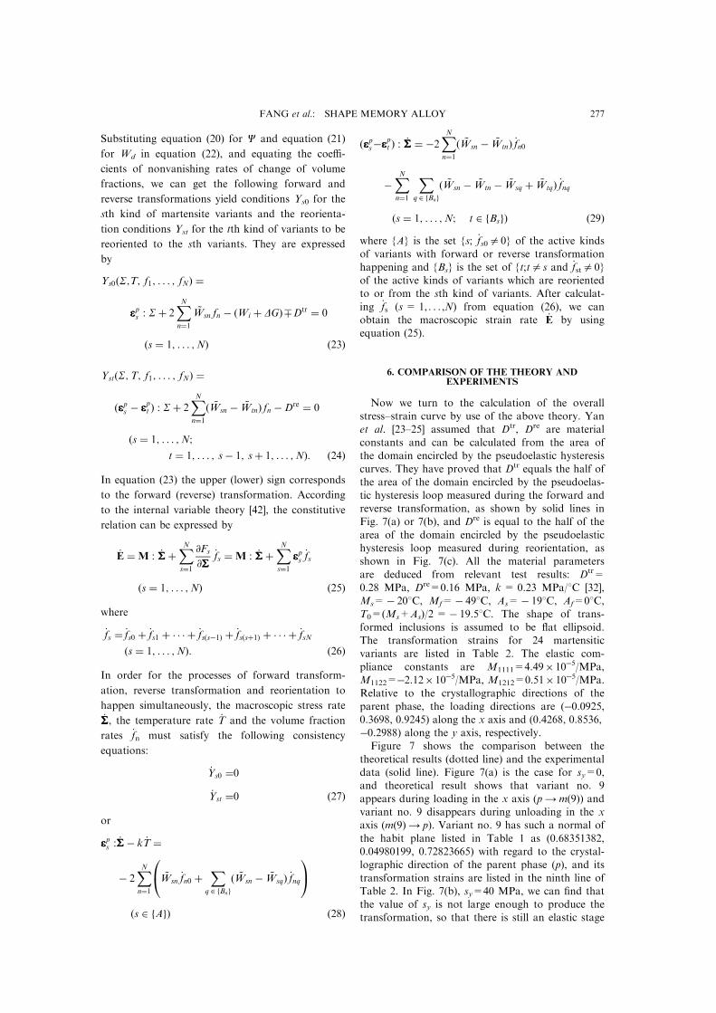
Now we turn to the calculation of the overallstress±strain curve by use of the above theory. Yanet al. [23±25] assumed that Dtr, Dre are materialconstants and can be calculated from the area of
the domain encircled by the pseudoelastic hysteresiscurves. They have proved that Dtr equals the half ofthe area of the domain encircled by the pseudoelas-
tic hysteresis loop measured during the forward andreverse transformation, as shown by solid lines inFig. 7(a) or 7(b), and Dre is equal to the half of the
area of the domain encircled by the pseudoelastichysteresis loop measured during reorientation, asshown in Fig. 7(c). All the material parameters
are deduced from relevant test results: Dtr=0.28 MPa, Dre=0.16 MPa, k= 0.23 MPa/8C [32],Ms=ÿ 208C, Mf=ÿ 498C, As=ÿ 198C, Af=08C,T0=(Ms+As)/2 =ÿ 19.58C. The shape of trans-
formed inclusions is assumed to be ¯at ellipsoid.The transformation strains for 24 martensiticvariants are listed in Table 2. The elastic com-
pliance constants are M1111=4.49� 10ÿ5/MPa,M1122=ÿ2.12�10ÿ5/MPa, M1212=0.51�10ÿ5/MPa.Relative to the crystallographic directions of the
parent phase, the loading directions are (ÿ0.0925,0.3698, 0.9245) along the x axis and (0.4268, 0.8536,ÿ0.2988) along the y axis, respectively.Figure 7 shows the comparison between the
theoretical results (dotted line) and the experimentaldata (solid line). Figure 7(a) is the case for sy=0,and theoretical result shows that variant no. 9
appears during loading in the x axis (p4 m(9)) andvariant no. 9 disappears during unloading in the xaxis (m(9) 4 p). Variant no. 9 has such a normal of
the habit plane listed in Table 1 as (0.68351382,0.04980199, 0.72823665) with regard to the crystal-lographic direction of the parent phase (p), and its
transformation strains are listed in the ninth line ofTable 2. In Fig. 7(b), sy=40 MPa, we can ®nd thatthe value of sy is not large enough to produce thetransformation, so that there is still an elastic stage
FANG et al.: SHAPE MEMORY ALLOY 277
during loading in x-direction. The theoretical calcu-
lation also predicts that no variant appears during
loading in the y axis, but variant no. 9 appears
during loading in the x axis (p 4 m(9)) and dis-
appears during unloading in the x axis (m(9) 4 p).
The calculation indicates that when sy is small, the
pseudoelasticity of the single crystal is due mainly
to the transformation between autensite and mar-
tensite. In this case, only one variant appears
during the loading and unloading processes. In
Fig. 7(c), sy=160 MPa, it is obvious that the value
of sy is large enough to produce the transformation,
so that in the sy0ey diagram (not shown here in
the ®gure) there appears a plateau of the pseudoe-
lastic hysteresis loop before loading in the x direc-
tion. The theoretical prediction indicates that
variant no. 5 appears during loading in the y axis
(p4 m(5)). During loading and unloading in the
x axis, the following transformation sequence
occurs: m(5)4 m(14), m(14)4 m(15), m(15)4 m(9),
m(9) 4 m(15), m(15)4 m(14), m(14) 4 m(5). The
normal of the habit planes and the transformation
strains for variant no. 5, 9, 14 and 15 are listed in
Table 1, respectively. Variant no. 5 ®nally disap-
pears during unloading in the y axis (m(5) 4 p).
This means that when sy is as large as to induce
transformation, the pseudoelasticity in the x direc-
tion is mostly related to the reorientation among
martensite variants. That is, the theory predicts the
appearance of more than two variants in the history
of loading and unloading, and this agrees with the
experimentally observed two ¯at plateaux in the
stress±strain curve. From the comparison shown in
Fig. 7, it may be concluded that the theory is accep-
table because theoretical results are close to exper-
imental data.
As mentioned before, Yan et al. ignored the sur-
face energy change in their model since they
assumed that all the p±m and m±m interfaces are
coherent for martensitic transformation. However,
we ®nd from Fig. 7 that the calculated hysteresis
loop curves are almost horizontal at the values of
transformation stress, which does not agree with
the experiments showing signi®cant hardening when
the strain is larger than 8%. We try to examine the
e�ect of the surface energy change. Following Song
et al. [26], denote WG as the surface energy between
the interface of the parent phase and martensite
variants:
WG � �h0 � hf m� �30�where f is the volume fraction of inclusions, h0, h
are material constants, and h = k(MsÿMf). Then,
the complementary free energy C of the constitutive
element per unit volume given in equation (20) is
rewritten as
C�SSS;T; f1; . . . ; fN� �ÿ �W� DGchem �WG ÿ SSS : E�: �31�
Following the above procedure, we can also predict
the overall stress±strain relation. In the calculation,
we can use h0=0, m = 5 as Song et al. [26] did,
and other material constants are the same as before,
for instance, k = 0.23 MPa/8C, and Ms=ÿ 208Cand Mf=ÿ 498C, we get h = 6.67 MPa. Figure 8
shows the comparison of the calculated results and
the measured data. We ®nd that when we consider
the surface energy change in our model, the for-
ward and reverse transformation will be a�ected,
while the surface energy change does not a�ect the
reorientation process. This is reasonable because, as
well-known, the m±m interfaces are coherent while
the p±m interfaces actually are not coherent for
martensitic transformation.
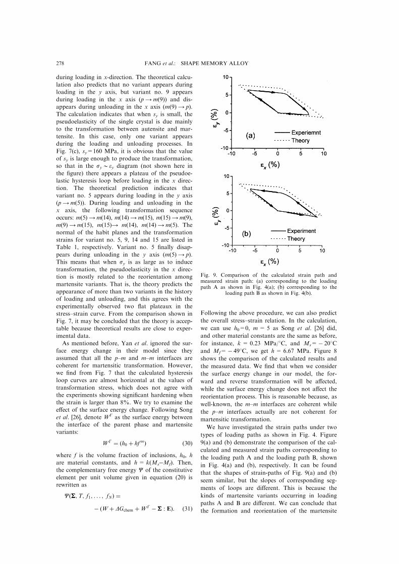
We have investigated the strain paths under two
types of loading paths as shown in Fig. 4. Figure
9(a) and (b) demonstrate the comparison of the cal-
culated and measured strain paths corresponding to
the loading path A and the loading path B, shown
in Fig. 4(a) and (b), respectively. It can be found
that the shapes of strain-paths of Fig. 9(a) and (b)
seem similar, but the slopes of corresponding seg-
ments of loops are di�erent. This is because the
kinds of martensite variants occurring in loading
paths A and B are di�erent. We can conclude that
the formation and reorientation of the martensite
Fig. 9. Comparison of the calculated strain path andmeasured strain path: (a) corresponding to the loadingpath A as shown in Fig. 4(a); (b) corresponding to the
loading path B as shown in Fig. 4(b).
FANG et al.: SHAPE MEMORY ALLOY278

variants are dependant upon the loading path sothat the strain path relies on the loading path too.
7. CONCLUSIONS
The biaxial loading tests for SMA single crystalsare very useful for revealing the basic characteristicsof thermoelastic martensite transformation inducedby stress and for verifying the constitutive models.
By applying di�erent combined loading histories oncruciform specimens, some new phenomena wereobserved. When the nominal loading stress sy is not
too high, the transformation stresses in the x-axisdirection increase as the values of stress sy increase,and the shape of the stress±strain curves has no
substantial change relative to the stress±strain curveof uniaxial loading, except that there is an elasticcontraction before loading in the x direction. When
sy is small, only the forward and reverse transform-ation will occur. However, when sy is high enoughto induce the transformation, the shape of thestress±strain curve for the x-axis direction changes
signi®cantly. Once sy is over the value correspond-ing to the start of transformation, the reorientationtakes place in the process of sx loading. The results
also indicate that the pseudoelasticity is so anisotro-pic that the transformation stress in the y directionis larger than that in the x direction. In addition,
by use of the crystallographic theory for martensitictransformation, the habit planes of the 24 variantsand the transformation plastic strain for the 24 var-
iants of the CuAlNi single crystal are predicted.Experimental data are compared with theoreticalcalculation based on the generalized micromecha-nics constitutive model. It can be found that the
model [23±26] can predict the evolutions of variantsboth in the forward/reverse transformation and inthe reorientation of martensite variants. In the
model, the surface energy change only a�ects theforward and reverse transformation while the reor-ientation process is not a�ected. The constitutive
model proposed is found acceptable since the theor-etical results are close to experimental data.
AcknowledgementsÐSupport from the National NaturalScience Foundation of China under NNSFC grants]19672026 and ]19891180 and from the State EducationCommission of China under the grant ]9400365 is grate-fully acknowledged. Japan Society for the Promotion ofScience (JSPS ID No. S-97341) is acknowledged for sup-port to KCH. The authors also thank the technical assist-ance from Z. J. Zhao, G. Xu, T. Xu and X. Y. Zhang inearly stages of the work.
REFERENCES
1. Otsuka, K. and Shimizu, K., Trans. JIM, 1974, 15,201.
2. Wechsler, M.S., Lieberman, D.S. and Read, T.A.,Trans. AIME, 1953, 197, 1503.
3. Waman, C. M. 1964. in Introduction to theCrystallography of Martensite Transformation.Macmillan, New York.
4. Bowles, J.S. and Mackenzie, J.K., Acta metall., 1954,2, 129.
5. Delaey, L., Krishnan, R.V., Tas, H. and Warlimont,H., J. Mater. Sci., 1974, 9, 1521.
6. Christian, J.W., Metall. Trans. A, 1982, 13A, 509.7. James, R.D.J., Mech. Phys. Solids, 1986, 34, 359.8. Ball, J.M. and James, R.D., Arch. Rat. Mech. Anal.,
1987, 100, 13.9. Bhattacharya, K., Acta metall., 1991, 39, 2431.10. Abeyaratne, R. and Knowles, J.K., J. Mech. Phys.
Solids, 1993, 41, 541.11. Abeyaratne, R., Chu, C. and James, R.D., ASME
Appl. Mech. Div., 1994, 189, 85.12. Falk, F., Acta metall., 1980, 28, 1773.13. Patoor, E., Eberhardt, A. and Berveiller, M., Arch.
Mech., 1988, 40, 775.14. Muller, I. and Xu, H., Acta metall., 1991, 39, 263.15. Chu, C. and James, R.D., ASME Appl. Mech. Div.,
1993, 181, 61.16. Tanaka, K., Oberaigner, E. R. and Fischer, F. D., in
Mechanics of Phase Transformations and ShapeMemory Alloys, Vol. AMD-Vol.189/PVP-Vol.292.ASME, ed. L. C. Brinson and B. Moran, 1994, p. 151.
17. Tanaka, K., Nishimura, F., Fischer, F. D. andOberaigner, E. R., in Proc. MECAMAT 95, J.Physique, Coll. 1, Suppl. J. Physique III, Vol. 6, ed. C.Lexcellent, E. Patoor and E. Gautier. Les Editions DePhysique, Les Ulis, 1996, pp. C1±455.
18. Liang, C. and Rogers, C.A., J. Engng. Math., 1992,26, 429.
19. Sun, Q.P. and Hwang, K.C., J. Mech. Phys. Solids,1993, 41, 1.
20. Sun, Q.P. and Hwang, K.C., Adv. Appl. Mech., 1994,31, 249.
21. Fischer, F.D., Sun, Q.P. and Tanaka, K., ASMEAppl. Mech. Rev., 1996, 49, 317.
22. Fischer, F.D., Oberaigner, E.R., Tanaka, K. andNishimura, F., Int. J. Solids Struct., in press.
23. Yan, W., Sun, Q. P. and Hwang, K. C., in Proc. 3rdAsia-Paci®c Symp. Advances in Engineering Plasticityand Its Application, Japan, 1996, p. 9.
24. Yan, W., Sun, Q.P. and Hwang, K.C., Int. J. Plastic.,1997, 13, 201.
25. Yan, W., Sun, Q.P. and Hwang, K.C., Sci. China,1998, A28, 275.
26. Song, G. Q., Sun, Q. P. and Hwang, K. C. 1998.IUTAM Symp. Variational Domain and Free-Boundary Problems in Solid Mechanics. Paris, France.Kluwer Academic, Amstedam.
27. Chen, X., Fang, D.N. and Hwang, K.C., SmartMater. Struct., 1997, 6, 145.
28. Chen, X., Fang, D.N. and Hwang, K.C., Acta mater.,1997, 45, 3181.
29. Lu, Z.K. and Weng, G.J., J. Mech. Phys. Solids, 1997,45, 1905.
30. Stam, G.ThM, v.d.Giessen, E. and Meijers, P., Int. J.Solids Struct., 1994, 31, 1923.
31. Okamoto, K., Ichinose, S., Morii, K., Otsuka, K. andShimizu, K., Acta metall., 1986, 34, 2065.
32. Horikawa, H., Ichinose, S., Morii, K., Miyazaki, S.and Otsuka, K., Metall. Trans. A, 1988, A19, 915.
33. Shield, T.W., J. Mech. Phys. Solids, 1995, 43, 869.34. Sittner, P., Hara, Y. and Tokuda, M., Metall. Mater.
Trans., 1995, 26A, 2923.35. Tokuda, M., Sittner, P., Takakura, M. and Ye, M.,
Mater. Sci. Res. Int., 1995, 1, 260.36. Lu, W., Fang, D. N. and Hwang, K. C. to be sub-
mitted.37. Dommerle, S. and Boehler, J.P., J. Mech. Phys.
Solids, 1993, 41, 143.38. Boehler, J.P., Demmerle, S. and Koss, S., Exp. Mech.,
1994, 1.
FANG et al.: SHAPE MEMORY ALLOY 279

39. Olson, G.B. and Cohen, M., Metall. Trans., 1976, 7A,1894.
40. Mori, T. and Tanaka, K., Acta metall., 1973, 21, 571.
41. Mura, T., in Micromechanics of Defects in Solids.Nijho�, Dordrecht, 1987.
42. Rice, J.R., J. Mech. Phys. Solids, 1971, 19, 433±455.
FANG et al.: SHAPE MEMORY ALLOY280