stress-intensity factor for a cracked sheet with riveted and uniformly
TRANSCRIPT
STRESS-INTENSITY FACTOR FOR A CRACKED SHEET WITH RIVETED AND UNIFORMLY SPACED STRINGERS
by C. C, Poe, Jr.
Lungley Research Center Humpton, Vu. 23365
N A T I O N A L A E R O N A U T I C S A N D SPACE A D M I N I S T R A T I O N 0 W A S H I N G T O N , D. C. MAY 1971
P
I
https://ntrs.nasa.gov/search.jsp?R=19710016458 2018-02-15T01:20:01+00:00Z

TECH LIBRARY KAFB, NM
17. Key-Words (Suggested by Authoris))
I Illill lllll lllll lllll lllll11111 lllll Ill1 Ill1
18. Distribution Statement
1. Report No. NASA TR R-358
19. Security Clanif. (of this report)
Unclassified
3. Recipient's Catalog No. I 2. Government Accession No. I
21. NO. of Pages 22. Rice* 20. Security Classif. (of this page)
Unclassified 62 $3.00 ~-
5. Report Date
May 1971
4. Title and Subtitle
STRESS-INTENSITY FACTOR FOR A CRACKED SHEET WITH RIVETED AND UNIFORMLY SPACED STRINGERS
7. Author(s)
C. C. Poe, Jr.
9. Performing Organization Name and Address
NASA Langley Research Center Hampton, Va. 23365
12. Sponsoring Agency Name and Address
National Aeronautics and Space Administration Washington, D.C. 20546
8. Performing Organization Report No.
L-6826 10. Work Unit No, 1 126-14-15-01 11. qntract or Grant No. I 13. Type of Report and Period Covered 1 Technical Report 14. Sponsoring Agency Code I
15. Supplementary Notes
. .
16. Abstract
The stress-intensity factor and forces in the most highly loaded rivet and stringer were calculated for a cracked sheet with riveted and uniformly spaced stringers. Two sym- metrical cases of crack location were considered - the case of a crack extending equally on both sides of a stringer and the case of a crack extending equally on both sides of a point midway between two stringers. The complete results are presented on design graphs for systematic variations of crack length, rivet spacing, stringer spacing, and stringer stiffness. The results show that the stress-intensity factor for the stiffened sheet is significantly less than that for an unstiffened sheet, except for crack lengths much less than the stringer spacing. Also, the forces in the most highly loaded stringer and rivet asymptotically approach limiting values for increasing crack length. limiting values of the stringer and rivet forces are smaller for stiffer or more closely spaced stringers or for more closely spaced rivets.
The stress-intensity factor and the
Stress-intensity factor Crack Stiffened panel
* For sale by the National Technical Information Service, Springfield, Virginia 22151

STRESS-INTENSITY FACTOR FOR A CRACKED SHEET WITH
RIVETED AND UNIFORMLY SPACED STRINGERS
By C. C. Poe, Jr. Langley Research Center
SUMMARY
The stress-intensity factor and forces in the most highly loaded rivet and stringer were calculated for a cracked sheet with riveted and uniformly spaced stringers. Two symmetrical cases of crack location were considered - the case of a crack extending equally on both sides of a s'tringer and the case of a crack extending equally on both sides of a point midway between two stringers. The complete results a r e presented as design graphs for systematic variations of crack length, rivet spacing, stringer spacing, and stringer stiffness. The results show that the stress-intensity factor for the stiffened sheet is significantly less than that for an unstiffened sheet, 'except for crack lengths much less than the stringer spacing. Also, the forces in the most highly loaded stringer and rivet asymptotically approach limiting values for increasing crack length. The s t ress - intensity factor and the limiting values of the stringer and rivet forces are smaller for stiffer o r more closely spaced stringers o r for more closely spaced rivets.
INTRODUCTION
The design of a complex structure for maximum residual strength and maximum resistance to fatigue-crack propagation requires quantitative knowledge of the s t resses in stiffened panels containing cracks. In recent years, considerable progress has been made in the s t r e s s analysis of cracked bodies by specifying a s t r e s s singularity near the crack tips. singular s t r e s s field, has been used successfully to estimate fracture strength and fatigue- crack growth rates in situations where the assumptions of linear elasticity are valid. However, the stress-intensity factor (or some similar parameter) has been calculated only for simple configurations and panels with one o r two stringers (refs. 1 to 10). Existing knowledge of stiffened panels is limited to experiments with box beams and tension panels (refs. 11 to 15).
The stress-intensity factor, a parameter that describes the intensity of the
In the present investigation, the stress-intensity factor and the forces in the most highly loaded rivet and stringer were calculated for a cracked sheet with riveted and uni- formly spaced stringers. The unknown rivet forces w e r e determined by requiring the

displacements at the rivets in the sheet and stringers to be equal. The stress-intensity factor for the cracked sheet was determined by superimposing the stress-intensity fac- tors for the rivet forces and for the applied uniaxial stress. Two cases of symmetrical crack location were considered - the case of a crack extending equally on both sides of a stringer and the case of a crack extending equally on both sides of a point midway between two stringers. Although the points of attachment are referred to as being riveted, the results apply equally well to spotwelded attachments.
The salient effects of independently varying stringer stiffness, str inger spacing, rivet spacing, and crack length are discussed in detail. The complete results for sys- tematic variations of stringer stiffness, str inger spacing, rivet spacing, and crack length are presented in the form of design graphs.
Aij
a
Bi
b
b0
d
E
F
K
- K
L
P
SYMBOLS
displacement a t ith rivet because of force of unity at jth rivet
half-crack length
displacement a t ith rivet because of applied uniaxial s t r e s s of unity
stringer spacing
specific value of stringer spacing
rivet diameter
Young's modulus of elasticity
maximum force in stringer
stress-intensity factor
stress-intensity-factor coefficient for rivet forces
stringer-load-concentration factor
point force applied to surface of crack
2

P
Q
r , d
S
t
V
W
X,Y
X0,YO
Z
Z
(Y
rivet spacing
rivet force
plane polar coordinates
applied uniaxial s t r e s s
thickness
y-component of displacement
stringer width
rectangular Cartesian coordinates
rivet coordinates
Westergaard stress function
complex variable
stringer-spacing reduction parameter
~Yi,(Y2,@3,a4
r
A
functions defined on page 17
function defined on page 17
function defined on page 18
ratio of stringer stiffness to total stiffness lJ.
U Poisson's ratio
5 distance from origin to point on crack surface
functions defined on page 14 p1 'pa
"Xx'"yy normal-s t r e s s components
3

- normal stress acting on crack surface
shearing-stress components Txy STXZ Jy z
@lyc$2
51
functions defined on page 14
function defined on page 16
Subscripts:
A pertaining to part A of sketch (g)
pertaining to par t B of sketch (g) B
i at ith rivet
j at jth rivet
lim limiting
S stringer
Superscript :
S stringer
FORMULATION OF PROBLEM
Unknown Rivet Forces
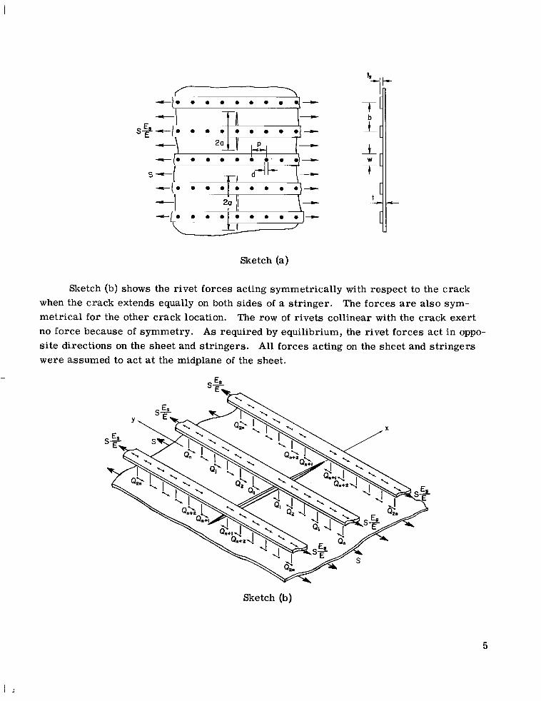
Sketch (a) shows a sheet stiffened by stringers of uniform size and spacing. The stringers a r e attached to the sheet with equally spaced rivets, and the sheet and stringers a r e subjected to the uniaxial s t resses S and S - respectively, which produce equal longitudinal strains at large distances from the crack. The sheet contains a crack that is located symmetrically with respect to the stringers; that is, a crack that extends equally on both sides of a stringer or equally on both sides of a point midway between two stringers. The crack is assumed to be coincident with a row of rivets. (The results in ref. 9 indicate that this is the most critical case.)
ES E ’
4
-10 0 0 0 0 0 0 0
s 4 -I T i l - I 1
-10 0 0 0 0 0 0 ' . 0\-
Sketch (a)
Sketch (b) shows the rivet forces acting symmetrically with respect to the crack when the crack extends equally on both sides of a stringer. The forces a r e also sym- metrical for the other crack location. The row of rivets collinear with the crack exert no force because of symmetry. As required by equilibrium, the rivet forces act in oppo- s i te directions on the sheet and stringers. All forces acting on the sheet and stringers were assumed to act at the midplane of the sheet.
Sketch (b)
5

The equations necessary to determine the unknown rivet forces Qj were obtained by equating the displacements at the rivet locations in the sheet and stringers. The dis- placements were written in te rms of the following influence coefficients: Aij and Bi, which represent the displacements in the cracked sheet at the ith rivet because of unit values of Qj and S, respectively; and Afj and Bf, which represent the displacements in the stringers at the ith rivet because of unit values of Qj and S%, respectively. Thus, the displacement a t the ith rivet in the sheet and stringers can be written
E
and
(2 1 $'= AS&. + B? - ES s 1 1 3 1 1 E j
respectively, where i and j refer to only those rivets in one quadrant of the sheet. The negative sign w a s introduced in equation (1) because the rivet forces act in opposite directions on the sheet and stringers. Equating the displacements in equations (1) and (2) and collecting te rms gives
(i = 1 , 2, 3, . . . ) (3)
A truncated se t of these simultaneous equations was solved for the unknown rivet forces. The expressions for the influence coefficients in equations (3) a r e given in appendix A.
Stress-Intensity Factor for Stiffened Sheet
For the symmetrical case of plane extension (mode I), the stresses near the crack tip in sketch (c) can be written as (ref. 16)
- cos - 1 - sin - sin- "XX-EZ 2 "( 2 e 38) 2
e 38 7 =- K sin _e cos- cos - "yrlz;;F 2 2 2
Txz = Tyz = 0
6

where K is the stress-intensity factor, and terms containing higher powers of r have been neglected.
B cau
- Sketch (c)
f symmetry, the uniaxial s t r e s s S and the symmetrical r r ay of rivet forces produce only an opening mode of crack deformation in the stiffened sheet. By using the principle of superposition, the total-stress-intensity factor can be written as
K = S G + (4 1 j
where S f i is the component due to the uniaxial s t r e s s S, and EjQj is the compo- nent due to the symmetrical se t of rivet forces Qj. For the case of plane s t ress , the coefficient is given (see ref. 17) for the symmetrical se t of point forces shown in sketch (d) as
- K = E L 3 nt + V)Ql - (1 + V ) Q J (5)
Sketch (d)
7
where
Y a1 =
and
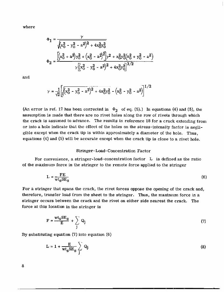
(An e r r o r in ref. 17 has been corrected in assumption is made that there are no rivet holes along the row of rivets through which the crack is assumed to advance. o r into a hole indicate that the effect of the holes on the stress-intensity factor is negli- gible except when the crack tip is within approximately a diameter of the hole. Thus, equations (4) and (5) will be accurate except when the crack tip is close to a rivet hole.
of eq. (5).) In equations (4) and (5), the
The results in reference 18 for a crack extending from
Stringer- Load- Concentration Factor
For convenience, a stringer-load-concentration factor L is defined as the ratio of the maximum force in the stringer to the remote force applied to the stringer
For a stringer that spans the crack, the rivet forces oppose the opening of the crack and, therefore, transfer load from the sheet to the stringer. Thus, the maximum force in a stringer occurs between the crack and the rivet on either side nearest the crack. The force at this location in the stringer is
wtsSEs + 1 Qj E F =
j
By substituting equation (7) into equation (6)
(7)
L = l + wtsSEs E C Q j j
a
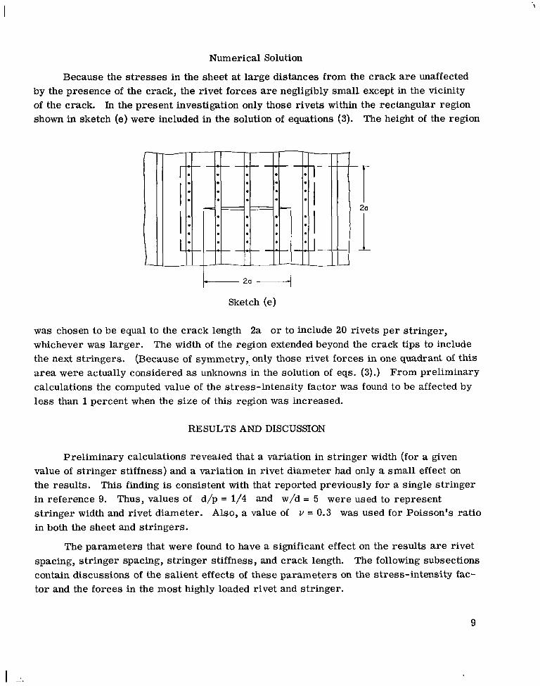
Num erica1 Solution
Because the stresses in the sheet at large distances from the crack are unaffected by the presence of the crack, the rivet forces are negligibly small except in the vicinity of the crack. In the present investigation only those rivets within the rectangular region shown in sketch (e) were included in the solution of equations (3). The height of the region
L 7 2a -4
Sketch (e)
was chosen to be equal to the crack length 2a or to include 20 rivets pe r stringer, whichever was larger. The width of the region extended beyond the crack tips to include the next stringers. a r ea were actually considered as unknowns in the solution of eqs. (3).) calculations the computed value of the stress-intensity factor was found to be affected by less than 1 percent when the s ize of this region was increased.
(Because of symmetry, only those rivet forces in one quadrant of this From preliminary
RESULTS AND DISCUSSION
Preliminary calculations revealed that a variation in stringer width (for a given value of stringer stiffness) and a variation in rivet diameter had only a small effect on the results. in reference 9. Thus, values of d/p = 1/4 and w/d = 5 were used to represent stringer width and rivet diameter. Also, a value of v = 0.3 was used for Poisson's ratio in both the sheet and stringers.
This finding is consistent with that reported previously for a single stringer
The parameters that were found to have a significant effect on the results are rivet spacing, stringer spacing, stringer stiffness, and crack length. The following subsections contain discussions of the salient effects of these parameters on the stress-intensity fac- tor and the forces in the most highly loaded rivet and stringer.
9
Appendix B presents graphs of the stress-intensity factor and the forces in the most highly loaded rivet and stringer for systematic variations of the significant parameters. Thus, these graphs may be used as design graphs.
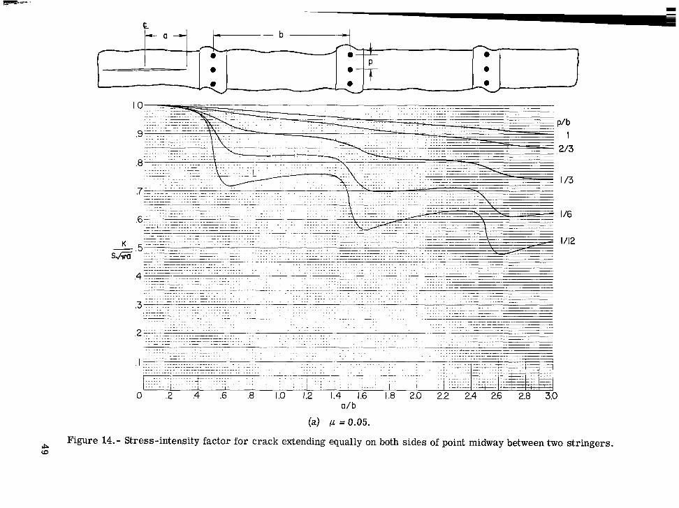
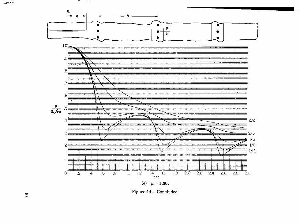
Stress-Intensity Factor
Figure 1 shows the effect of stringer stiffness on the relationship between the stress-intensity factor and half-crack length for a crack extending equally on both sides of a stringer and a crack extending equally on both sides of a point midway between two stringers. The stress-intensity factor and the ha1.f-crack length and rivet spacing are made nondimensional by dividing by the stress-intensity factor of an unstiffened sheet S Fa and the stringer spacing b, respectively. The ratio of rivet to stringer spacing is fixed a t p/b = 1/6. The stiffness of the stringers is expressed as p , the ratio of total str inger stiffness to total panel stiffness. For stringers of uniform size and spacing
The curves show that the stress-intensity factor of the stiffened sheet is essentially equal to that of an unstiffened sheet when the crack length is small compared to stringer spacing. Moreover, for a crack located midway between two stringers, K = S p a for crack lengths up to one-half the stringer spacing. is small compared to the stringer spacing, the stringers may give little improvement to the strength of the cracked sheet. the stress-intensity factor considerably below that of an unstiffened sheet, especially when the crack tip is slightly beyond a stringer as evidenced by the minimum points in the curves. It should again be pointed out that the assumption is made that there are no rivet holes along the row of rivets through which the crack is assumed to advance. However, the effect on the stress-intensity factor of such rivet holes is negligible except when the crack tip is within approximately one diameter of a hole. The curves for the various values of p show that the stress-intensity factor is lower for stiffer stringers. The value of p = 1 represents the limiting case when the stiffness of the s t r ingers becomes very large compared to the stiffness of the sheet and, thus, gives a lower bound on the stress-intensity factor. It is important to note that significant reductions in the s t ress- intensity factor occur for moderately stiff stringers. In fact, 80 percent of the maximum possible reduction in the stress-intensity factor occurs when the stringers a r e as stiff as the sheet ( p = 0.5).
Thus, in cases where the crack length
For longer cracks, however, the stringers can reduce
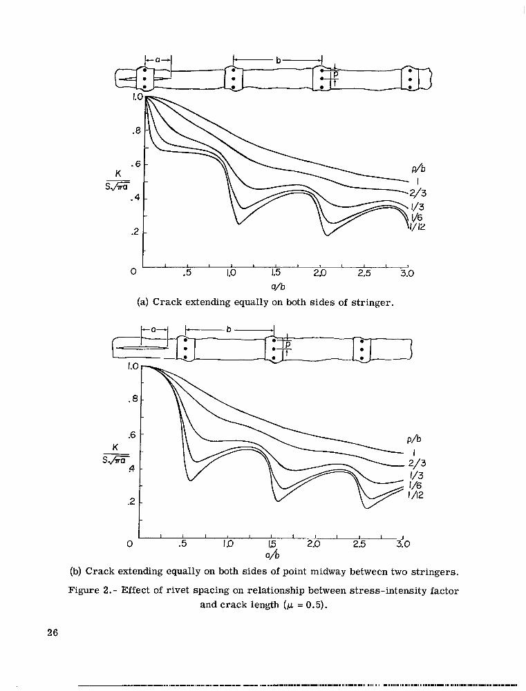
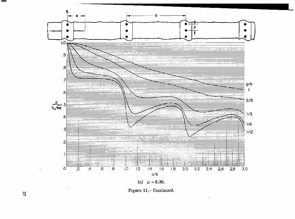
Figure 2 shows the effect of rivet spacing on the relationship between the s t ress - intensity factor and half-crack length for both crack locations. The stiffness of the
10

st r ingers is fixed at p, = 0.5. The curves for various ratios of rivet to stringer spacing show that the stress-intensity factor is also lower for more closely spaced rivets. However, when the crack tip is near a stringer, the curves continue to decrease with decreasing rivet spacing, and very small minimum values occur in the curves at each stringer. Thus, the effectiveness of the stringers in arresting a crack may increase significantly with decreasing rivet spacing. It is important to note, however, that inte- gral str ingers (a limiting case of riveted stringers with small rivet spacing) are not the most effective stringers for arresting o r impeding cracks because the crack front also tends to progress through the stringers. As the rivet spacing decreases, the s t ress - intensity factor approaches the lower bound, which corresponds to the case of a continu- ously attached stringer (ref. 9). When the crack tip is between stringers, this lower bound is apparently reached with the small rivet spacings.
Figure 3 shows the effect of stringer spacing on the relationship between the s t ress - intensity factor and half-crack length for both crack locations. str ingers is fixed at p = 0.5. In order to show directly the effect of stringer spacing, the half-crack length and rivet spacing a r e normalized by dividing by a fixed value of stringer spacing bo where p/bo = 1/6. The curves for the smaller values of stringer spacing, a! = 1/2 and 1/4, show that the stress-intensity factor is also lower for more closely spaced stringers except at the minimum points. These exceptions occur at the minimum points because the more widely spaced stringers have a larger individual stiff- ness and, thus, a larger local effect. lower bound on the stress-intensity factor for decreasing stringer spacing.
The stiffness of the
The curve for a = 1/4 appears to represent a
It is important to note in figures 1 to 3 that the curves for the stress-intensity fac- tor as a function of crack length have lower bounds for increasing stringer stiffness and decreasing rivet spacing and stringer spacing. Thus, optimum values of these parameters may exist when other design considerations are taken into account.
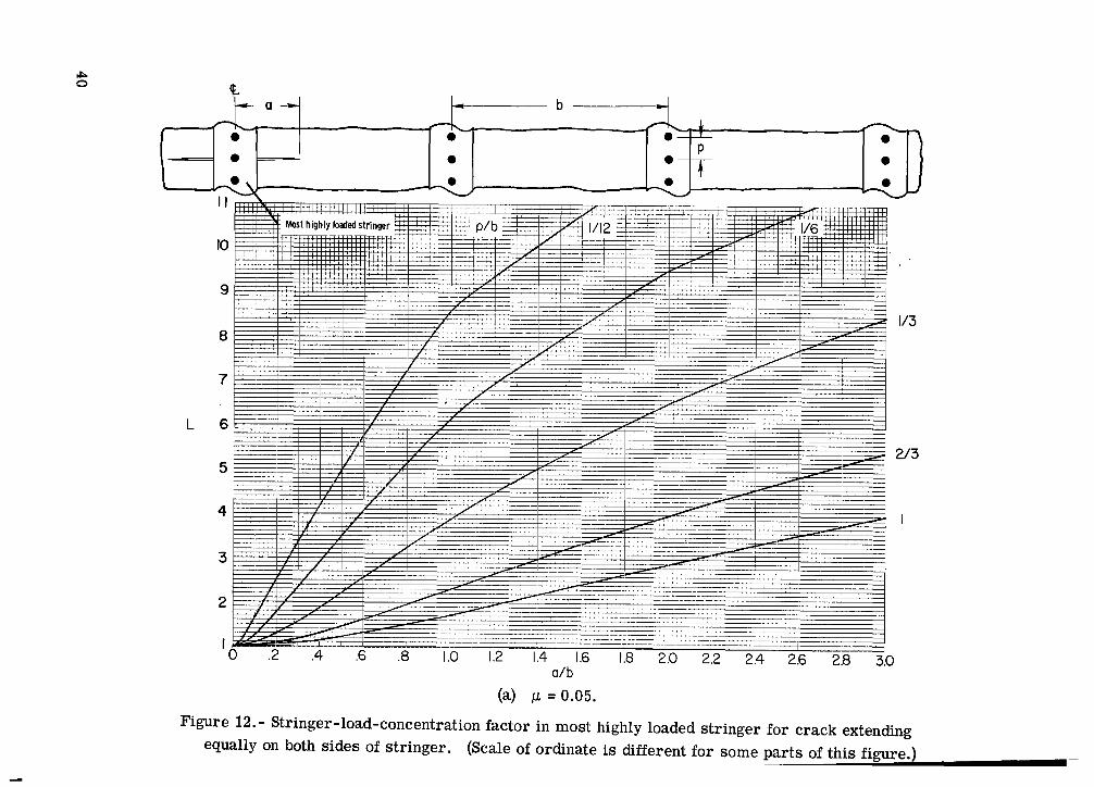
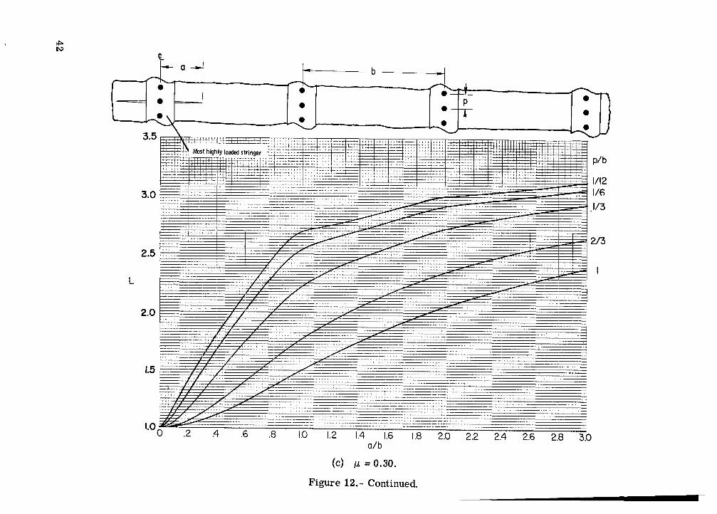
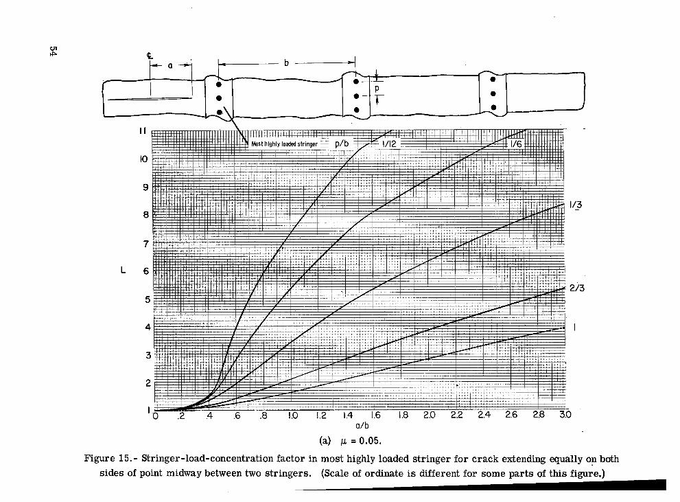
Force in Most Highly Loaded Stringer
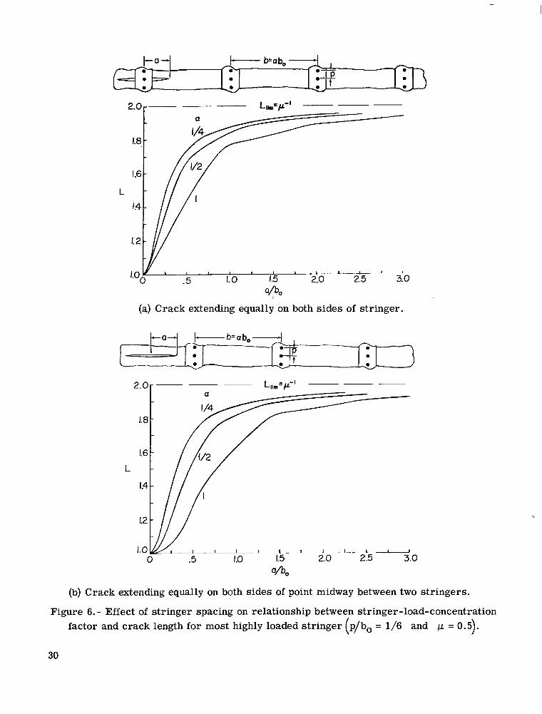
Figures 4 to 6 show the effects of stringer stiffness, rivet spacing, and stringer spacing on the relationship between the force in the most highly loaded stringer and half-crack length. factor L. middle two stringers, depending on the crack location.
The force in the stringer is shown as the stringer-load-concentration The most highly loaded stringers were always the middle stringer o r the
The curves show that L is essentially unity €or small cracks and increases with increasing crack length. For very long cracks, the curves approach limits that are inde- pendent of crack location. values can be shown to be the reciprocal of the stringer stiffness ratio 1.1. Consider the case in which,the crack has progressed entirely across the width of the sheet. The force
For s t r ingers of uniform size and spacing, these limiting
11

that must be transferred from the sheet to the s t r ingers is btS per stringer. By adding this increment to the applied force the limiting force in a stringer becomes
By substituting equation (10) into equation (6) the limiting value of L becomes
btE Llim = 1 + - WtSES
The right-hand side of equation (11) is the reciprocal of the stringer stiffness ratio p. (See eq. (9).) Thus,
Values of Llim calculated by equation (12) are shown in figures 4 to 6 as horizontal dashed lines. most highly loaded stringer can be much larger than the stress applied remotely to the stringers. Therefore, str ingers with small stiffness a r e more likely to fail than stringers with large stiffness when the sheet is cracked.
The curves in figure 4 show that for small values of 1-1 the stress in the
Figures 5 and 6 show that for larger rivet spacing and for larger stringer spacing longer cracks are required for L to reach Llim.
Force in Most Highly Loaded Rivet
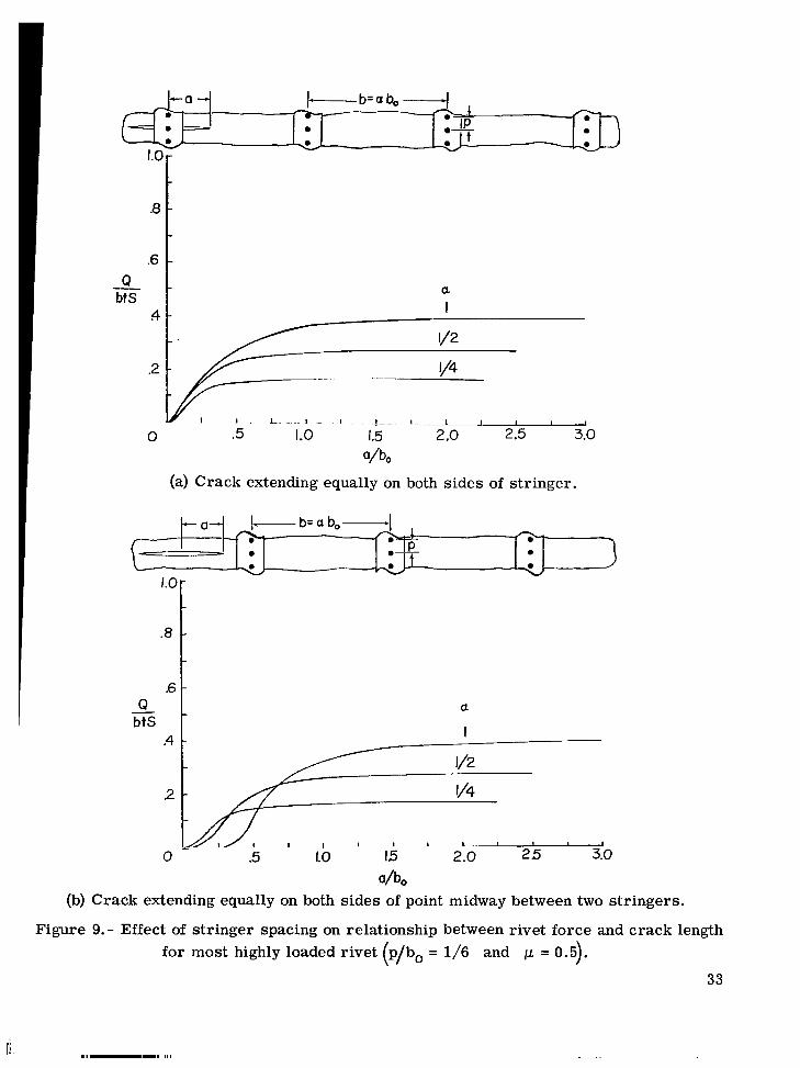
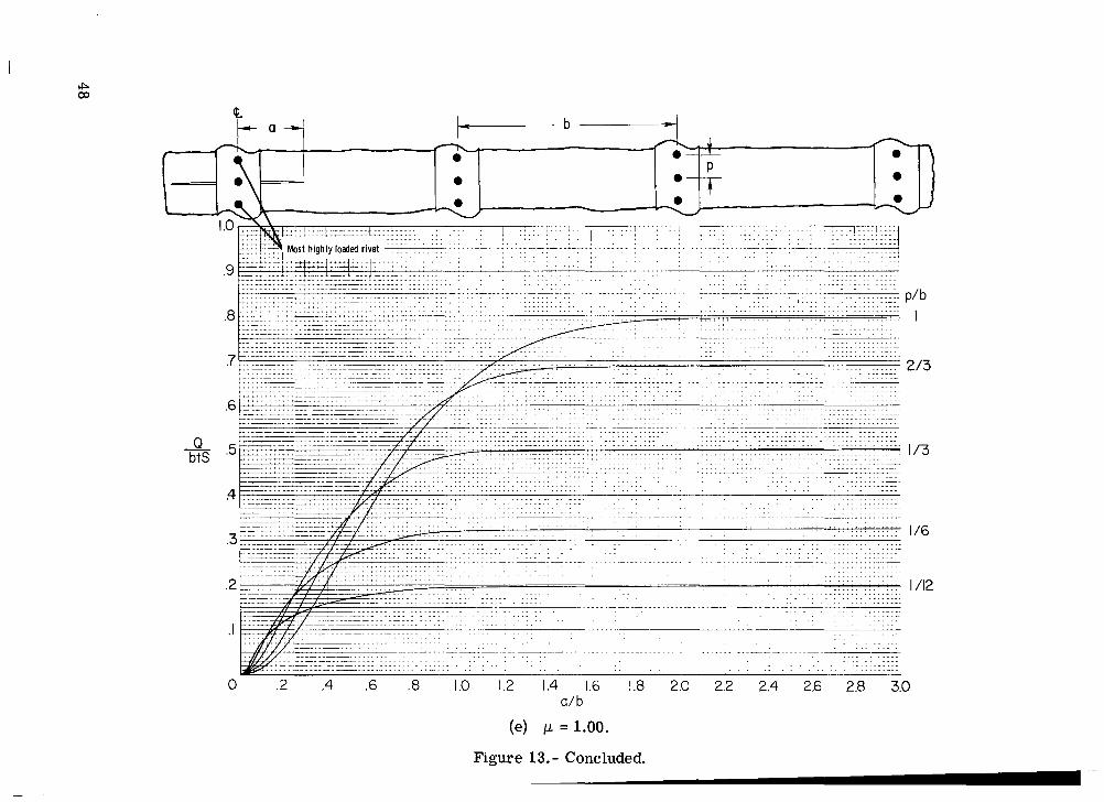
Figures 7 to 9 show the effect of stringer stiffness, rivet spacing, and stringer spacing on the relationship between the force in the most highly loaded rivet and the half- crack length. The rivet force was normalized with respect to the force btS, which is the maximum force that can be transferred from the cracked sheet to a stringer. The most highly loaded rivets were always the rivets nearest the crack in the most highly loaded stringers.
The curves show that the force in the rivet increases with crack length and asymp- totically approaches a limiting value that is independent of crack location. stringer stiffness, larger rivet spacing, or larger stringer spacing, longer cracks are required for the rivet force to reach its limiting value. For cracks of intermediate length, the curves cross one another and general conclusions cannot be made about the effect of stringer stiffness, rivet spacing, or stringer spacing.
For smaller
12
The limiting values of rivet force observed in figures 7 to 9 cannot be derived like those for the stringer force given by equation (12). However, values of rivet force for very long cracks were estimated from graphs of rivet force plotted against the inverse of crack length. These estimated values of limiting rivet force are plotted in figure 10 against p for the various values of CY and p/b. The curves show that the limiting value of rivet force is smaller for stiffer o r more closely spaced stringers or for more closely spaced rivets.
CONCLUDING REMARKS
The stress-intensity factor and forces in the most highly loaded stringer and rivet w e r e calculated for a cracked sheet with riveted and uniformly spaced stringers. The calculations were made for two symmetrical cases of crack location - the case of a crack extending equally on both sides of a stringer and the case of a crack extending equally on both sides of a point midway between two stringers. The results a r e presented in the form of design graphs for a systematic variation of crack length, str inger stiffness, rivet spacing, and stringer spacing.
For small cracks the stress-intensity factor for a stiffened sheet is essentially equal to that of an unstiffened sheet. For longer cracks the stress-intensity factor is reduced significantly by the stringers. The stress-intensity factor is smaller for s t i f fe r o r more closely spaced s t r ingers or for more closely spaced rivets. However, the stress-intensity factor has a lower bound with respect to each of these parameters, and an optimum value of each parameter may exist when other design considerations a r e taken into account.
The forces in the most highly loaded rivet and stringer approach limiting values with increasing crack length. As in the case of the stress-intensity factor, these limiting values of force a r e smaller for s t i f fe r or more closely spaced stringers o r for more closely spaced rivets.
Langley Research Center, National Aeronautics and Space Administration,
Hampton, Va., February 24, 1971.
13

APPENDIX A
EQUATIONS FOR DETERMINING INFLUENCE COEFFICIENTS OF
CRACKED SHEET AND STRINGERS
Cracked Sheet
Applied uniaxial stress.- For the infinite sheet containing a crack in sketch (f), the displacement in the y-direction for a state of plane stress can be developed from refer- ence 19 as
where
Sketch ( f )
The influence coefficients Bi are determined from equation (13) by setting the stress S equal to unity.
14
APPENDIX A - Continued
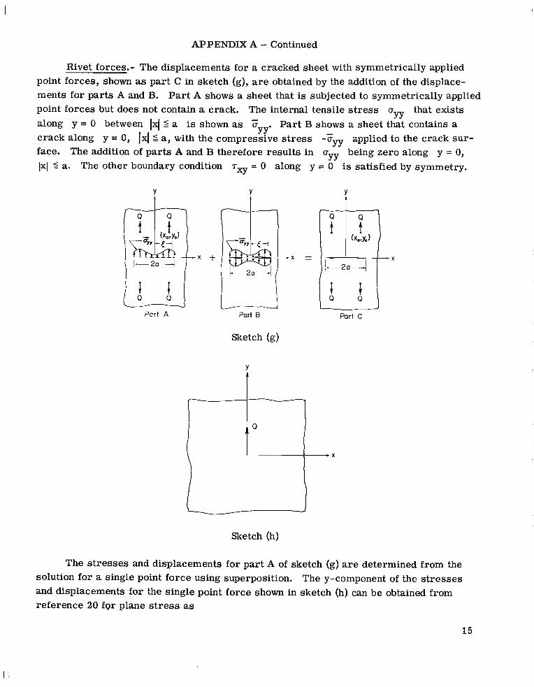
Rivet forces.- The displacements for a cracked sheet with symmetrically applied point forces, shown as part C in sketch (g), are obtained by the addition of the displace- ments for parts A and B. Part A shows a sheet that is subjected to symmetrically applied point forces but does not contain a crack. The internal tensile s t r e s s u that exists along y = 0 between 1x1 5 a is shown as u Part B shows a sheet that contains a crack along y = 0, 1x1 6 a, with the compressive s t r e s s -ayy applied to the crack sur- face. The addition of par ts A and B therefore results in uyy being zero along y = 0, 1x1 5 a. The other boundary condition T~ = 0 along y = 0 is satisfied by symmetry.
- YY YY' -
Y t
Part A
Y t
- x +
Part 0
Sketch (g)
Y
.X \
Sketch (h)
The s t resses and displacements for par t A of sketch (g) are determined from the solution for a single point force using superposition. The y-component of the s t resses and displacements for the single point force shown in sketch (h) can be obtained from reference 20 fgr plane stress as
15

APPENDIX A - Continued r -
v = - - 4 k 3 4ntE - u) ln(x2 + y2) + (1 + v)
and (T = -
YY 4Trt + Y
Equation (14) cannot be used in its present form to calculate the displacement caused by the force Q because there is a singularity at the origin. To circumvent this problem, the Doint force Q is assumed to be distributed uniformly over the rivet diameter d. - - Replacing x by x - x in equation (14) and integrating with respect to x from to -d, the displacement becomes 1
2
1 - -d 2
(1 6)
For d - 0, equation (16) reduces to equation (14). By translating the origin in equa- tion (16) so that the point force is located at a point (xo,yo) and by adding the displace- ments for point forces located at @xo,*y0), the displacement field for par t A of sketch (g) is written as
1 + ~ ) ( 3 - V)QO v* = ( 16atE
where
16
a + 1 ) 2 + a i
+ 1)2 s?! = (a1 + 1)
+ @3 L
+ (a2 + I) In
f

APPENDIX A - Continued
and 2(x - xo)
d CYl =
2(x+xo)
2(Y - Yo)
2(Y 4- Yo)
d a 2 =
“3 =
“4 =
d
d
By using the same procedure and equation (15), the stress field for part A of sketch (g) is written as
f
UYY = wp)( “1 2 “4 + “ 4 2 + “ 2 + 4 2 “4 “ ? + a 3 “3 2 4 % ) cY2+cY3
7
The stress cyy that must be removed in part A of sketch (g) is obtained from equa- tion (18) by setting y = 0 and x = 5. Thus,
where
1 + 1
17
APPENDIX A - Continued
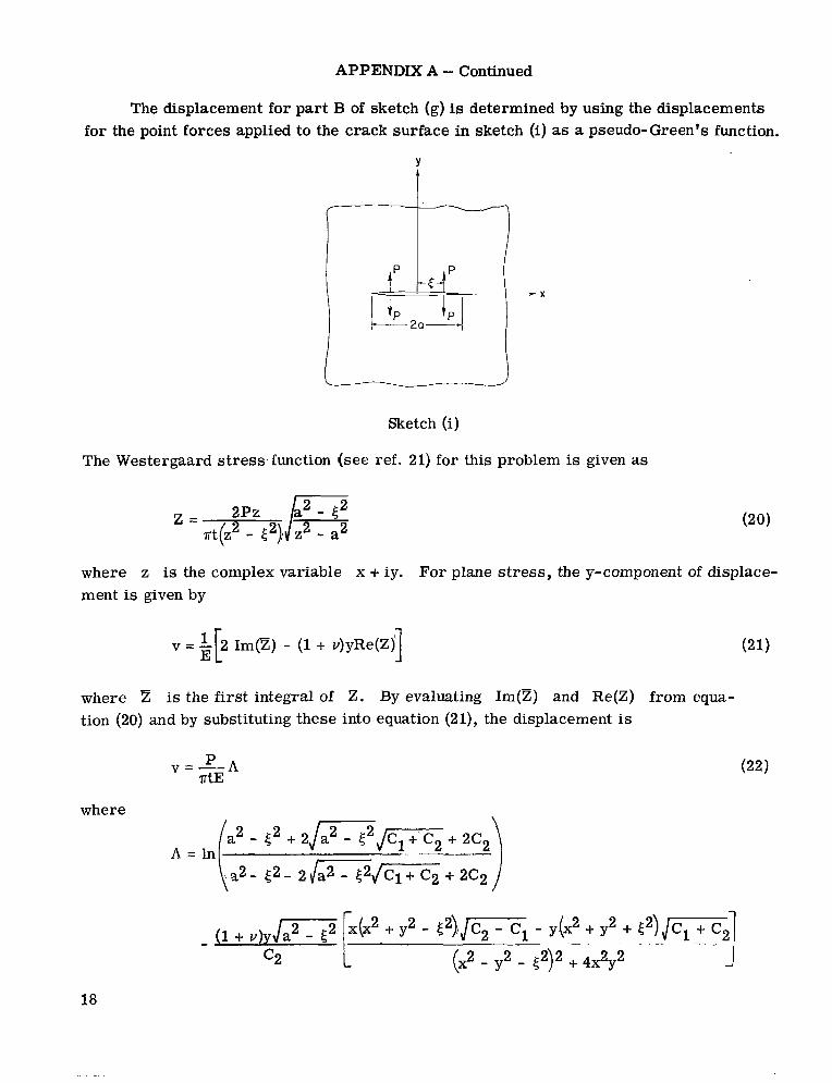
The displacement for par t B of sketch (g) is determined by using the displacements for the point forces applied to the crack surface in sketch (i) as a pseudo-Green's function.
Y
I I
1 Sketch (i)
The Westergaard s t r e s s , function (see ref. 21) for this problem is given as
where z is the complex variable x + iy. For plane stress, the y-component of displace- ment is given by
v = '[2 Im@) - (1 + v)yRe(Z)i E 1 (21)
where z is the f i rs t integral of Z. By evaluating Im@) and Re(Z) from equa- tion (20) and by substituting these into equation (21), the displacement is
P v =----A r tE
where
c2 t 18
and
APPENDIX A - Continued
c2 = /- By substituting tcYy d5 over the crack, the displacements for par t B of sketch (g) become
for P in equation (22) and by integrating with respect to 5
VB = - la E A d 5 nE 0 YY
Now, by substituting equation (19) for FU, equation (23) can be written
(23)
By adding the displacements for par ts A and B (sketch (g)), which are given by equa- tions (17) and (24), the displacement for a cracked sheet with symmetrically applied point forces becomes
r-
The integral in equation (25) is readily evaluated numerically on a digital computer.
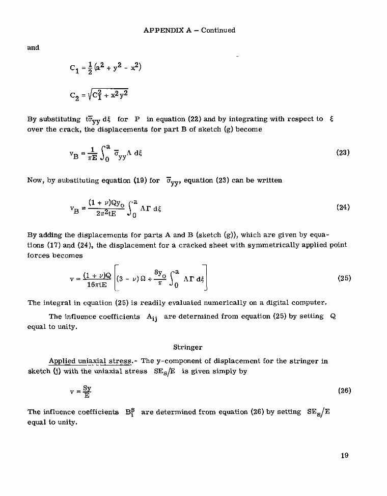
The influence coefficients Aij are determined from equation (25) by setting Q equal to unity.
Stringer
Applied uniaxial stress.- The y-component of displacement for the stringer in sketch (j) with the uniaxial stress SEs/E is given simply by
The influence coefficients Bf are determined from equation (26) by setting SEs/E equal to unity.
19
APPENDIX A - Continued
X
Sketch (j)
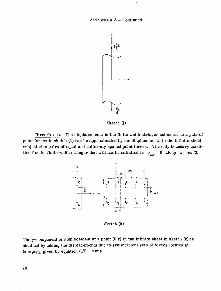
Rivet forces.- The displacements in the finite width stringer subjected to a pair of point forces in sketch (k) can be approximated .by the displacements in the infinite sheet subjected to pairs of equal and uniformly spaced point forces. The only boundary condi- tion for the finite width stringer that will not be satisfied is uxx = 0 along x = &w/2.
Sketch (k)
The y-com nent of displacement t a point (0,y) in the infinit sheet i sketch (k) is obtained by adding the displacements due to symmetrical s e t s of forces located at (ulw,*yo) given by equation (17). Thus
20

APPENDIX A - Concluded
1 + ~ ) ( 3 - v)Q 8 ~ t s E s
v = (
where
and
for n = 1, 2, . . . . The influence coefficients AS. are determined from equation (27) by setting the rivet force Q equal to unity.
11
21
!

APPENDIX B
DESIGN GRAPHS
Figures 11 to 16 show graphs of the stress-intensity factor, the stringer-load- concentration factor for the most highly loaded stringer, and the rivet force for the most highly loaded rivet plotted against the ratio a/b for various values of the ratios p/b and p . The stress-intensity factor and the rivet force are made nondimensional by dividing by the stress-intensity factor of an unstiffened sheet S F a and the force btS, respectively. Values of d/p = 1/4, w/d = 5, and v = 0.3 were used to represent the rivet diameter, stringer width, and Poisson's ratio, respectively. Although the points of attachment are referred to as being riveted, the results apply equally well to spot- welded attachments. The range in values of p and the ratio p/b are sufficient to include most stiffener-sheet configurations. The curves are shown for values of a/b 2 3 and, thus, include crack lengths up to s ix times the stringer spacing. The graphs a r e shown for two symmetrical cases of crack location - the case of a crack extending equally on both sides of a stringer and the case of a crack extending equally on both sides of a point midway between two stringers.
The curves for the symmetrical cases of crack location may be used to obtain an upper bound on the stress-intensity factor for a nonsymmetrical crack by entering a curve with the larger value of half-crack length. The row of rivet holes through which the crack is assumed to advance is not accounted for in the calculations for the stress-intensity fac- tor. However, crack-propagation times calculated by using these values should be con- servative because of the time required for a crack to initiate from a hole. The present stress-intensity-factor calculations a r e based on the classical linear theory of elasticity. Hence, caution should be exercised when applying the results to cases in which the stringers yield.
22

REFERENCES
1. Romualdi, J. P.; Frasier , J. T.; and Irvin, G. R.: Crack-Extension-Force Near a Riveted Stiffener. NRL Rep. 4956, U.S. Navy, Oct. 11, 1957.
2. Sanders, J. Lyell, Jr.: Effect of a Stringer on the Stress Concentration Due to a Crack in a Thin Sheet. NASA TR R-13, 1959. (Supersedes NACA TN 4207.)
3. Romualdi, James P.; and Sanders, Paul H.: Fracture Arrest by Riveted Stiffeners. AFOSR TR 60-174, U.S. Air Force, Oct. 1960.
4. Isida, Makoto; and Itagaki, Yoshio: Stress Concentration at the Tip of a Central Transverse Crack in a Stiffened Plate Subjected to Tension. Fourth U.S. National Congress of Applied Mechanics, Vol. Two, Amer. SOC. Mech. Eng., c.1962, pp. 955-969.
Proceedings of the
5. Leybold, Herbert A.: A Method for Predicting the Static Strength of a Stiffened Sheet Containing a Sharp Central Notch. NASA TN D-1943, 1963.
6. Greif, Robert; and Sanders, J. L., Jr.: The Effect of a Stringer on the Stress in a Cracked Sheet. Trans. ASME, Ser. E: J. Appl. Mech., vol. 32, no. 1, Mar. 1965, pp. 59-66.
7. Isida, M.: The Effect of a Stringer on the Stress Intensity Factors for the Tension of a Cracked Wide Plate. Dept. Mech., Lehigh Univ., Sept. 1965.
8. Isida, M.; Itagaki, Y.; and Iida, S.: On the Crack Tip Stress Intensity Factor for the Tension of a Centrally Cracked Strip With Reinforced Edges. Univ., Sept. 1965.
Dept. Mech., Lehigh
9. Bloom, J. M.; and Sanders, J. L., Jr.: The Effect of a Riveted Stringer on the Stress in a Cracked Sheet. Trans. ASME, Ser. E: J. Appl. Mech., vol. 33, no. 3, Sept. 1966, pp. 561-570.
10. Figge, I. E.; and Newman, J. C., Jr.: Prediction of Fatigue-Crack-Propagation Behavior in Panels With Simulated Rivet Forces. NASA TN D-4702, 1968.
11. Hardrath, Herbert F.; Leybold, Herbert A.; Landers, Charles B.; and Hauschild, Louis W.: TN 3856, 1956.
12. Hardrath, Herbert F.; and Whaley, Richard E.:
Fatigue -Crack Propagation in Aluminum -Alloy Box Beams. NACA
Fatigue-Crack Propagation and Residual Static Strength ,of Built-up Structures. NACA TN 4012, 1957.
13. Hardrath, Herbert F.; and Leybold, Herbert A,: Further Investigation of Fatigue- Crack Propagation in Aluminum-Alloy Box Beams. NACA TN 4246, 1958.
23

14. Whaley, Richard E.; and Kurzhals, Peter R.: Fatigue-Crack Propagation in Aluminum- Alloy Tension Panels. NASA TN D-543, 1960.
15. Leybold, Herbert A,: Residual Static Strength of Aluminum-Alloy Box Beams Containing Fatigue Cracks in the Tension Covers. NASA TN D-796, 1961.
16. Paris, Paul C.; and Sih, George C.: Stress Analysis of Cracks. Fracture Toughness Testing and Its Applications. Spec. Tech. Publ. No. 381, Amer. SOC. Testing Mater., c.1965, pp. 30-81..
17. Paris, Paul C.: Application of Muskehlishvili's Methods to the Analysis of Crack Tip Stress Intensity Factors for Plane Problems. Pt. III. Inst. Research, Lehigh Univ., June 1960.
18. Newman, J. C., Jr.: Stress Analysis of Simply and Multiply Connected Regions Containing Cracks by the Method of Boundary Collocation. M.S. Thesis, Virginia Polytech. Inst., May 1969.
19. Westergaard, H. M.: Bearing Pressures and Cracks. J. Appl. Mech., vol. 6, no. 2, June 1939, pp. A-49 - A-53.
20. Love, A. E. H.: A Treatise on the Mathematical Theory of Elasticity. Fourth ed. (First Amer. Printing), Dover Publ., 1944, p. 209.
21. Irwin, G. R.: Analysis of Stresses and Strains Near the End of a Crack Traversing a Plate. Trans. ASME, Ser. E: J. Appl. Mech., vol. 24, no. 3, Sept. 1957, pp. 361-364.
24

t I I k -1 1 1 . 1 1 1 1 1
0 .5’ 1.0 1.5 2.0 2.5 3.0 a/b
(a) Crack extending equally on both sides of stringer.
.2 - I
I I I I I I I I I I I I 1 -
0 .5 1.0 1.5 2.0 2.5 3.0 a/b
(b) Crack extending equally on both sides of point midway between two stringers.
Figure 1. - Effect of stringer stiffness on relationship between stress-intensity factor and crack length (p/b = 1/6).
25
- .2 -
I I a I 1 I I I t I I I I
0 ' .5 1.0 1.5 2b 2.5 3.0 a/b
(a) Crack extending equally on both sides of stringer.
-2 -
I I I I I I I I I J
0 .5 ID 15 ' 2.b I 2 5 3.0 a h
(b) Crack extending equally on both sides of point midway between two stringers.
Figure 2. - Effect of rivet spacing on relationship between stress-intensity factor and crack length ( p = 0.5).
26

t *T K
S i
.2 i a
- 1/4 .2 -
I I I I I 1 1 I I I I 1 I
0 .5 I ,o 15 2.0 25 3.0
(a) Crack extending equally on both sides of stringer.
.8 -
K - 6 - s m -
4 -
.2 -
~
0
a
I I 1 I I I I I
-5 1.0 1.5 2.0 . 2.5 3.0 O/bO
(b) Crack extending equally on both sides of point midway between two stringers.
Figure 3. - Effect of stringer spacing on relationship between stress-intensity factor and crack length (p/bo = 1/6 and p = 0.5).
27

P I O y - L ,b= p- 1
L .3
5
I . 1 1 - j
1.5 2.0 2.5 3.0 a/b
(a) Crack extending equally on both sides of stringer.
L it 3 .3
2 - .5
I 1 I I I I
.5 1.0 1.5 2 .o 3.0 I 0
a/b (b) Crack extending equally on both sides of point midway between two stringers.
Figure 4. - Effect of stringer stiffness on relationship between stringer -load-concentration factor and crack length for most highly loaded stringer (p/b = 1/6).
28

b
P/b 1/12 L,h=p-l - - - 2.0-- - -
L
a/b
(a) Crack extending equally on both sides of stringer.
0 .5 I .o 15 2 .o 2.5 3.0 Q/b
(b) Crack extending equally on both sides of point midway between two stringers.
Figure 5. - Effect of rivet spacing on relationship between stringer -1oad-concentration factor and crack length for most highly loaded stringer ( p = 0.5).
29
a p 0
(a) Crack extending equally on both sides of stringer.
(b) Crack extending equally on both sides of point midway between two stringers.
Figure 6. - Effect of stringer spacing on relationship between stringer-load-concentration factor and crack length for most highly loaded stringer (p/bo = 1/6 and p = 0.5).
30

*8 t Q btS
0 .5 1.0 1.5 2.0 2.5 3.0 a/b
(a) Crack extending equally on both sides of stringer.
0 Q/b
(b) Crack extending equally on both sides of point midway between two stringers.
Figure 7.- Effect of stringer stiffness on relationship between rivet force and crack length for most highly loaded rivet (p/b = 1/6).
31

.6 1
“ t
PAJ I
0 .5 1.0 I .5 2.0 2.5 3 .O
(a) Crack extending equally on both sides of stringer. a /b
Q btS
.6
4 -
d b (b) Crack extending equally on both sides of point midway between two stringers.
Figure 8.- Effect of rivet spacing on relationship between rivet force and crack length for most highly loaded rivet ( p = 0.5).
32
.
Q btS -
.8
.6
c
-
- -
-
a I
t / / V I 1 L . . . l - 1 - !-- 1 I I I 1 1
0 .5 1.0 1.5 2 .o 2.5 3.0
a/b, (a) Crack extending equally on both sides of stringer.
Q btS -
1, 0
/ / I / I I I 1 I I 1 1 - 1 I
.5 1.0 15 2.0 25 3.0
db, (b) Crack extending equally on both sides of point midway between two stringers.
Figure 9.- Effect of stringer spacing on relationship between rivet force and crack length for most highly loaded rivet p bo = 1/6 and p = 0.5).
33 ( /

l im (Q/botS) Wb+W
0 I I 1 I I I I A - I J
Figure 10.- Effect of stringer stiffness, str inger spacing, and rivet spacing on limiting force in most highly loaded rivet.
34

W UI
a a a - a a
-
e t- a - 4
.. . . . . . . . . . . . . . . . . . . . .
I .o r -
.9 I 213
.a I13
*__-__ ........ . . . . . . . . ........ . . . '.--*....l ...*.... ' , .-: , ................ __1__._ ....... ....,... . . . . . . .. ....+.... ........ - .......... _...< . . . , .... 0 .2 .4 .6 .8 1.0 1.2 1.4 1.6 1.8 2.0 2.2 2.4 2.6 2.8 3.0
a / b
(a) p = 0.05.
Figure 11.- Stress-intensity factor for crack extending equally on both sides of stringer.

w Q, 1
I .w
.9
.8
.7
.6
: .5
.4
.3
.2
. I
0 1.4 1.6 1.8 2.0 2.2 2.4 2.6 2.8 3.(
213
113
I 16
1/12
a/b
(b) 1-1 =0.10.
Figure 11. - Continued.
o 0 - 0
0 0 0
0 P
...... ___ .a
7 P/b I
21.3
.6
s 2 . 5 I /3
I16
1/12
4
.3
.2
... . . . . . . . . . . . . . . . - . . . . . . . . . . . . . . . . . . . . . .
. I
0 .2 .4 .6 .8 1.0 1.2 1.4 1.6 1.8 2.0 2.2 2.4 2.6 2.8 3 .O a/b
(c) p = 0.30.
Figure 11.- Continued.

w 03
a/b
(d) 1-1 =0.50.
Figure 11. - Continued.

-
0 .2 .4 .6 .8 1.0 1.2 1.4 1.6 1.8 2.0 2.2 2.4 2.6 2.8 3.0
w CD
a/b
(e) 1-1 = 1.00.
Figure 11. - Concluded.
CP 0
(a) 1.1 = 0.05. Figure 12. - Stringer-load-concentration factor in most highly loaded stringer for crack extending
equally on both sides of stringer. (Scale of ordinate is different for some parts of this figure.)

(b) 1.1 =0.10.
Figure 12.- Continued.
a/b
(c) =0.30.
Figure 12.- Continued.

a/b
(d) p =0.50.
Figure 12.- Concluded.

A A
Q btS
_._-. ~
~
_____-_- - ~
0 .2 .4 .6 .8 1.0 1.2 1.4 1.6 1.8 2.0 2.2 2.4 2.6 2.8 3.0 a/b
(a) p = 0.05.
Figure 13.- Force in most highly loaded rivet for crack extending equally on both sides of stringer.

(b) p =0.10.
Figure 13.- Continued.

I .o
.9
.8
.7
Q btS
.6
.5
.4
.3
.2
.I
0
P/b 2/3 I 13 I
I 16
1/12
.2 .4 .6 .8 1.0 1.2 1.4 1.6 1.8 2.0 2.2 2.4 2.6 2.8 3.0 a/b
( c ) p =0.30.
Figure 13.- Continued.

0 .2 4 .6 .8 1.0 1.2 1.4 1.6 1.8 2.0 2.2 2.4 2.6 2.8 3.0 a /b
(d) 1.1 =0.50.
Figure 13. - Continued.
. . . . , . . . . . . . . . , . . , . . . .
. . - . . . . - -
. . . . ,
. . . . .
. . . . . . .
0 .2 .4 .6 .8 1.0 1.2 1.4 1.6 1.8 2.0 2.2 2.4 2.6 2.8 3.0 a/b
(e) p = 1.00.
Figure 13.- Concluded.
-&&=-
I .o
.9 . ...... .
.8 ... . . . . - - .. . . . . . . .
.7
.6
P/b I
213
1/12
.. - .....
. . . . . . . . . . . . . . . . . . . . . . . . . . . . . . . . . . . . . .
... . ..
... . . . . . . . . . . . . . . . -___._____ . . . . . . . . . . . . . . . . . . . . . . . . . - - - _ _ _ ~ . . . . . . . . . . . . . . . . . . . _L
. . . . . . . . . . .
_ I
. . _ . _ , _ . _ . , * . , . _ . .............. . . . . . . . . . . . . . . . . . , . ] :~ I:*I .-_ - I _, , , I , I . ,
I . . . . . . . . . . . .., ... ....,.. . . . . . . , . . , . . , .... t _ .
0 .2 .4 .6 .8 1.0 1.2 1.4 1.6 1.8 2.0 2.2 2.4 2.6 2.8 3.0 a / b
Figure 14.- Stress-intensity factor for crack extending equally on both sides of point midway between two stringers. rp Eo

.1
P 0
0 0
0 0 .f
__
P/b I
213 . .
I /3
I /6
I /I? - . . . . . . .
.. .- .............. . . . . . . . . . . . . . .. . . . . . . . . . . . . . . . . . . . . . .~ .. . . -
. . . . . . .
. . . . . . . . . . . . . . . . . . . . . . . . . . . . . . . . . . . -
a /b
(b) p = 0.10.
Figure 14.- Continued.

e
P/b I
213
I /3 I16 I /I2
0 .2 .4 .6 .8 1.0 1.2 1.4 1.6 1.8 2.0 2.2 2.4 2.6 2.8 3.0 a/b
(C) /J = 0.30.
Figure 14. - Continued.

0
0
. . . .
. . . . . , . . . . . . . ___ ._____~
0 .2 .4 .6 .8 1.0 1.2 1.4 1.6 1.8 2.0 2.2 2.4 2.6 2.8 3.0
a /b
(d) p =0.50.
Figure 14. - Continued.
0 0
0 0
c 0
P
-- I .a
.9
.8
.7
.6
1 .3 213
113 .2 116
1/12
. I
0 .2 .4 .6 .8 1.0 1.2 1.4 1.6 1.8 2.0 2.2 2.4 2.6 2.8 3.0 a/b
(e) p = 1.00.
Figure 14. - Concluded.
I I
10
9
8
7
L 6
5
4
3
2
I
I / 3
2/3
1
a/b
(a) p = 0.05.
Figure 15. - Stringer-load-concentration factor in most highly loaded stringer for crack extending equally on both sides of point midway between two stringers. (Scale of ordinate is different for some parts of this figure.)

L
P i b
1/12
1/6
2 /3
I
3
(b) p =0.10.
Figure 15. - Continued.

a / b
(c ) 1-1 = 0.30.
Figure 15. - Continued.

m 4
a/b
(d) p =0.50.
Figure 15.- Concluded.

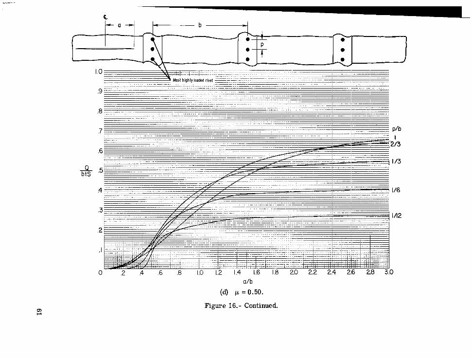
Figure 16.- Force in most highly loaded rivet for crack extending equally on both sides of point midway between two stringers.

0
0
P
I .o
.9
.a
.7
.6
1/12 1/3 213
I .3
.2
.I
0 .2 .4 .6 .8 1.0 1.2 1.4 1.6 1.8 2.0 2.2 2.4 2.6 2.8 3.0 a/b
(b) p = 0.10.
Figure 16. - Continued.

ua 0
- e 0
I .o
.9
Q btS -
.0
.7
P/b 2/3 t/3
I16
.6
.5 I
.4
1/12 .3
- - __-
.2
.I
0 .2 .4 .6 .8 1.0 12 1.4 1.6 1.8 2.0 2.2 2.4 2.6 2.8 3.0 a/b
(c) p =0.30.
Figure 16.- Continued.
0
0 P
.3 1/12
.2
.I
0 .2 .4 .6 .8 1.0 1.2 1.4 1.6 1.8 2.0 2.2 2.4 2.6 28 3.0 a /b
(d) p =0.50.
Figure 16.- Continued.

r
0 .2 .4 .6 .8 1.0 1.2 1.4 1.6 1.8 2.0 2.2 2.4 2.6 2.8 3.0 a/b
(e) p = 1.00.
F i m e 16. - Concluded.
m 03 N m