stress analysis of masonry vaults and static efficacy of frp … · stress analysis of masonry...
TRANSCRIPT

Available online at www.sciencedirect.com
International Journal of Solids and Structures 44 (2007) 8028–8056
www.elsevier.com/locate/ijsolstr
Stress analysis of masonry vaults and staticefficacy of FRP repairs
Alessandro Baratta, Ottavia Corbi *
Department of ‘‘Scienza delle Costruzioni’’, University of Naples ‘‘Federico II’’, Italy
Received 26 July 2006; received in revised form 29 March 2007Available online 2 June 2007
Abstract
In the paper, the basic principles for the analysis of structures made by Not-Resisting-Tension (NRT) material areintroduced; the theory is then applied for investigating the static behaviour of a NRT masonry arch model and to testthe effect of reinforcements made by FRP strips of variable length. A wide experimental campaign is developed and numer-ical/experimental comparison is provided in order to evaluate the skill of the adopted model in capturing the real behav-iour of the structure with or without reinforcement.� 2007 Elsevier Ltd. All rights reserved.
Keywords: Masonry-like structures; Not-Resisting-Tension Model; Theoretical approaches; Numerical–experimental validation
1. Introduction
The big deal in treating structural problems relevant to the monumental and historical heritage, mostly con-sisting of masonry constructions, lays in understanding the behavior of such constructions, in correctly inter-preting the symptoms of possible disease and in forecasting the effect of reinforcements.
Masonry structures are often modeled by means of the assumption of the so-called Not-Resisting-Tension
(NRT) material (Heyman, 1966, 1969; Baratta et al., 1981; Baratta and Toscano, 1982; Di Pasquale, 1982;Franciosi, 1980), which is a simple and complete phenomenological model for interpreting the behaviour ofmechanical bodies made by not-cohesive compact materials.
Structural analysis under ordinary loading conditions as well as for collapse load evaluation can be per-formed by means of suitable extensions to NRT structures of basic theoretical approaches for elastic struc-tures (Del Piero, 1989; Como and Grimaldi, 1983; Baratta, 1984, 1991, 1996; Baratta and Voiello, 1987;Bazant, 1995, 1996, 1997; Khludnev and Kovtunenko, 2000; Baratta and Corbi, 2003a,b,c).
The results that can be obtained by performing a numerical investigation on NRT structures are able tocapture the essential behaviour of the analogous masonry structure, keeping in mind, that in general, for struc-tural assessment, in particular of a masonry building, it is necessary to evaluate both the behaviour under
0020-7683/$ - see front matter � 2007 Elsevier Ltd. All rights reserved.
doi:10.1016/j.ijsolstr.2007.05.024
* Corresponding author. Tel.: +39 0817683739; fax: +39 0817683719.E-mail address: [email protected] (O. Corbi).

Nomenclature
k load multiplierk* collapse multiplierb statically admissible multiplierc kinetically sufficient multiplierp, F surface and body force vectors�F; F fixed and variable parts of the body force vector�p; p fixed and variable parts of the surface force vectorT reaction vectoran unit vector orthogonal to the constrained surface St
u displacement vector�u constrained displacement vectoruf mechanismu
cf collapse mechanism
e strain tensoree, ef elastic and fracture strain tensorsecf mechanism fracture tensor
efx, efy, cfxy fracture strain components in the x–y planeef1, ef2 principal fracture strain componentsr stress tensorr 0 NRT admissible (semi-negative definite) stress tensorrb statically admissible stress fieldrx, ry, sxy tensor stress components in the x–y planer1, r2 principal stress componentsC, D tensor of elastic constants and its inverse$(Æ) symmetric gradient operatordiv(Æ) divergence operatorV volume of the bodySp loaded surface of the bodySt constrained surface of the bodyB0 class of statically admissible multipliersC0 class of kinetically sufficient multipliersU domain of admissible displacementsUf set of all mechanismsUf domain of admissible NRT fracture tensorsU�f domain of admissible NRT fracture tensors (principal)F0 set of all admissible fracture fieldsR domain of admissible NRT stress tensorsR* domain of admissible NRT stress tensors (principal)D0 set of all statically admissible stress fieldsEðu; efÞ Potential Energy functionalC(r) Complementary Energy functionalhr(Æ) NRT admissibility stress constraint functionshe(Æ) NRT admissibility fracture constraint functionsG body forces in the archN(s) normal force in the portal at the curvilinear abscissa ‘‘s’’T(s) shear force in the portal at the curvilinear abscissa ‘‘s’’M(s) bending moment in the portal at the curvilinear abscissa ‘‘s’’S(s) vector of components N(s), T(s), M(s)
A. Baratta, O. Corbi / International Journal of Solids and Structures 44 (2007) 8028–8056 8029

Xi redundant unknown internal forcesAr(s) compressed reactive part of the cross-section at abscissa ‘‘s’’Af(s) inert fractured part of the cross-section at abscissa ‘‘s’’e(s) eccentricity of the normal force on the cross-section at the abscissa ‘‘s’’
8030 A. Baratta, O. Corbi / International Journal of Solids and Structures 44 (2007) 8028–8056
loading patterns corresponding to the operation of the building and the safety margins with respect to ultimatelimit states like structural collapse.
On the other side, relatively recent developments in composite materials technology offer a wide range ofpossibilities of reinforcement interventions on existing masonry structures, which are basically characterizedby some very desirable advantages such as low invasiveness and high reversibility, in the respect of the pre-existing structural apparatus.
Under this perspective the skill of exactly predicting the behaviour of reinforcements in Fiber Reinforced
Polymers (FRP), i.e. composite materials characterised by a polymeric matrix reinforced with continuousfibres, and their coupling with the refurbished structure, is a pretty attractive feature of research (Schwegler,1994; Faza et al., 1994; El-Badry, 1996; Traintafillou, 1996; Weaver, 1997; Briccoli and Rovero, 2000; Barattaand Corbi, 2001a,b, 2003d,e,f).
2. An insight in the NRT behaviour
The basic assumption of no-tension masonry model coincides with the hypothesis that the tensile resistanceis null. Under this hypothesis, no-tension stress fields are selected by the body through the activation of anadditional strain field, the fractures (see Heyman, 1966, 1969; Baratta and Toscano, 1982; Baratta, 1991;Bazant, 1996; Di Pasquale, 1984). The behaviour in compression can be modeled in a number of different ways(elastic linear, elastic non-linear, elastic–plastic; isotropic, anisotropic, etc.), without altering substantially nei-ther the results nor the mathematical treatment of the problem; some convenience exists for practical appli-cations in assuming a isotropic linearly elastic model, in order to keep limited the number of mechanicalparameters to be identified for masonry, since increasing the number of data causes increasing uncertaintyin the results. Because of these reasons, and being clearly understood that there is no difficulty in introducingmore sophisticated models, it is convenient to set up the fundamental theory on the basis of the assumptionthat the behaviour in compression is indefinitely linearly elastic.
In details, in a NRT solid the equilibrium against external loads is required to be satisfied by admissible
stress fields, which imply pure compression everywhere in the solid. Compatibility of the strain field can beassured by superposing to the elastic strain field an additional fracture field, which does not admit contractionin any point and along any direction; that is to say that the stress tensor r must be negative semi-definite every-where in the solid (i.e. r must be an element of the set of negative semi-definite stress tensors R), while thefracture strain field ef is required to be positive semi-definite (i.e. ef must be an element of the set Uf of positivesemi-definite fracture strain tensors) (Fig. 1). In the following the dependency of the variables on the point ofthe solid is sometimes implicit and plane stress and strain fields are referred to.
In symbols, the material should satisfy the following conditions
Semi-definiteef Positive
r Negative
�!
efa P 0
ra 6 0
�8a 2 ra; e ¼ ee þ ef ¼ Crþ ef ð1Þ
where ra is the set of directions through the generic point in the solid, ‘‘a’’ is one of such directions, ef is thefracture strain that is assumed to superpose to the elastic strain ee in order to anneal tensile stresses if possible,and C denotes the tensor of elastic constants.
The material admissibility conditions for strain and stress reported in Eq. (1) can be synthetically referredto by the set of inequalities he(ef) P 0 and hr(r) 6 0, respectively.
The relationship between the stress state on one side and the possibly active fracture strain on the otherside, can be set in a number of different ways. If stability of the material is assumed in the Drucker’s sense,the classical Drucker’s postulate holds for the fracture strain

σ2, εf2
σ1, εf1
≤σ≤σ
=Σ0
0
2
1*
≤σ≤σ
=Σ0
0
2
1*
≤σ≤σ
=Σ0
0
2
1*
≥ε≥ε
Φ*f =
0
0
2f
1f
τxy
εfx
εfy
σxσy
γfxy
26 4 2-2 -4 -6
64
0-2
-4-6
6
4
2
-2
-4
-6
Σ
Φ
a b12
f
Fig. 1. The stress and the fracture admissible domains (a) R and Uf in the spaces of tensor components, (b) R* and the fracture U�f in thespaces of principal components.
A. Baratta, O. Corbi / International Journal of Solids and Structures 44 (2007) 8028–8056 8031
r0 � rð Þ � ef 6 0 8r0 2 R
r1ef1 ¼ 0; r2ef2 ¼ 0f g ) r � ef ¼ 0 ð2Þ
and the fracture-law is analogous to the associated flow-law in plasticity, being ruled by the normality law withreference to the admissible principal domain R*.
In Eq. (2) r 0 represents any admissible stress state other than the real one r, and the principal tensors’ com-ponents relevant to the principal directions are denoted by (Æ)1 and (Æ)2, respectively. From Eq. (2) one can inferthat the internal fracture work r Æ ef is always equal to zero.
3. Basic principles for structural analysis of NRT bodies
3.1. General overview
Analysis of NRT bodies proves that the stress, strain and displacement fields obey extremum principles ofthe basic energy functionals.
Therefore the behaviour of NRT solids under ordinary loading conditions can be investigated by means ofsome extensions of basic energy approaches to NRT bodies (Baratta et al., 1981; Baratta and Toscano, 1982;Del Piero, 1989; Baratta, 1984, 1996; Baratta and Voiello, 1987; Baratta and Corbi, 2003a).
In details, the solution of the NRT structural problems can be referred to the two main variationalapproaches:
– the minimum principle of the Potential Energy functional;– the minimum principle of the Complementary Energy functional.
In the first case the displacements and the fractures are assumed as independent variables; the solution dis-placement u0 and fracture strain efo fields are found as the constrained minimum point of the Potential Energyfunctional, under the constraint that the fracture field is positively semi-definite at any point.
The approach based on the minimization of the Complementary Energy functional assumes the stresses asindependent variable. The complementary approach is widely adopted since the existence and uniqueness ofthe NRT solution are always assured in terms of stress, if some conditions on the compatibility of the loads aresatisfied. The stress field r0 can, then, be found as the constrained minimum of the Complementary Energyfunctional, under the condition that the stress field is in equilibrium with the applied loads and is compressiveeverywhere in the body.
The solution of both problems can be numerically pursued by means of Operational Research methods (seei.e. Rao, 1978) suitably operating a discretization of the analysed NRT continuum (Baratta and Corbi, 2003e).

8032 A. Baratta, O. Corbi / International Journal of Solids and Structures 44 (2007) 8028–8056
One should notice that discussion about existence of the solution actually can be led back to some Limit Anal-ysis of the considered NRT continua (Baratta and Corbi, 2003a).
In this regard, a special formulation of Limit Analysis for No-tension structures has been performed, allow-ing the set up of theorems analogous to the basic kinetic and static theorems of classical Limit Analysis; thus,one can establish efficient procedures to assess structural safety versus the collapse limit state (see e.g. Comoand Grimaldi, 1983) by specializing and applying fundamental theorems of Limit Analysis to NRT continua(Franciosi, 1980; Como and Grimaldi, 1983; Baratta, 1991; Bazant, 1995, 1997; Khludnev and Kovtunenko,2000; Baratta and Corbi, 2003b,c).
In details, the individuation of the collapse (live) load multiplier for NRT continua can be referred to theapproaches relying on the two main Limit Analysis theorems:
– the static theorem;– the kinetic theorem.
This means that, after defining the classes of statically admissible and kinetically sufficient load patterns,Limit Analysis allows individuating the value of the live load multiplier limiting the loading capacity of thebody, i.e. evaluating the collapse live load and/or the safety factor versus collapse. One should note that ina NRT structure its own weight (the dead load) is an essential factor of stability, while collapse can be pro-duced by not-admissible additions of the variable component of the load pattern.
Duality tools may also be successfully applied in order to check the relationships between the two theoremsof Limit Analysis (Baratta and Corbi, 2003g,h, 2004).
3.2. Analysis under operational loading conditions: energy principles for NRT bodies
3.2.1. Potential Energy approach
As already mentioned in the above, the solution displacement and fracture strain fields are found as theconstrained minimum point of the Potential Energy functional, under the constraint that the fracture fieldis positively semi-definite at any point. Let consider the surface and body forces, p and F, respectively, actingon the loaded surface of the solid Sp and in its volume V, the strain field e given by the superposition of anelastic ee and an inelastic ef (fracture) component, the displacement field u, and the compatibility operator ofthe solid $(Æ)1 such that
1 Th
e ¼ ee þ ef ¼ ru: ð3Þ
The Total Potential Energy functional Eðu; efÞ can be written in the formEðu; efÞ ¼1
2
ZVðru� efÞ � ½Dðru� efÞ�dV�
ZSp
p � udS�Z
VF � udV ð4Þ
with D the inverse tensor of C and (Æ) meaning scalar product.In Eq. (4), the first term defines the elastic energy stored in the body and the second and third terms rep-
resent the work developed by the surface and body forces, respectively.It can be demonstrated (Baratta and Corbi, 2003a) that the solution (u0, efo) satisfies the condition
Eðu0; ef0Þ ¼ minu2Uef2F 0
Eðu; efÞ ¼ E0 ð5Þ
yielding the minimum of the Potential Energy constrained by the condition of admissibility of displacementand fracture strain, with U the set of admissible displacements (i.e. such that the displacement functionsare continuous, derivable and compatible with the external constraints on the body) and F0 the variety ofadmissible fracture fields (i.e. positive semi-defined tensor fields ef, such that ef belongs to the set Uf in everypoint of the body).
e operator $(Æ) denotes the symmetric component of the gradient of the vector field argument.

A. Baratta, O. Corbi / International Journal of Solids and Structures 44 (2007) 8028–8056 8033
More explicitly, Eq. (5) can be set up in the form
Find minu2Uef2F 0
Eðu; efÞ
Sub fheðefÞP 0
8<: ð6Þ
with the constraints he(ef) given by
heðefÞ ¼efx P 0
efy P 0
efxefy � 14c2
f P 0
8><>:
in a generic reference frame.
3.2.2. Complementary Energy approachThe stress field can be found, in turn, as the constrained minimum of the Complementary Energy functional
C(r), under the condition that the stress field r is in equilibrium with the applied loads and compressiveeverywhere.
The Complementary functional C(r) can be written in the form
CðrÞ ¼ 1
2
ZV
r � CrdV�Z
St
T � �udS; T ¼ ran ð7Þ
where T is the vector of reactions given by the product T = ran with an the unit outgoing vector orthogonal tothe constrained surface St at the constrained locations, and �u is the vector of constrained displacements on St.
In Eq. (7), the first term defines the (complementary) elastic energy stored in the body and the second termrepresents the reactions’ work developed at the constrained points on St.
It can be proved (Baratta and Toscano, 1982) that the solution stress field (i.e. the stress field r0 such thatthe elastic strains Cr0 can be made compatible with a continuous displacement field by the superposition of afracture strain field), satisfies the condition
Cðr0Þ ¼ minr2D0
CðrÞ ¼ C0 ð8Þ
with D0 the set of statically admissible stress fields (i.e. tensor fields r(x) in equilibrium with the applied loadsand locally admissible at every point of the body); in other words the stresses in solution are identified by theminimum of the Complementary Energy constrained by the condition that stress fields are admissible and inequilibrium with the applied loads.
More explicitly, Eq. (8) can be set up in the form
Find minr2D0
CðrÞ
Sub
divrþ F ¼ 0 in V
ran ¼ p on Sp
�hrðrÞP 0
8><>:
8>>>><>>>>:
ð9Þ
with the constraints hr(r) given by
hrðrÞ ¼rx 6 0
ry 6 0
snw � rxry 6 0
8><>:
in a generic reference frame.
3.2.3. Solution search
The solution of both problems given in Eqs. (6) and (9), after discretization, can be numerically obtained bymeans of Operational Research methods and procedures, since they generally result in non-linear program-ming problems.

Fig. 2. Solution search pattern.
8034 A. Baratta, O. Corbi / International Journal of Solids and Structures 44 (2007) 8028–8056
In Fig. 2 the contour lines of one of the two energy functionals are drawn, and the hypothetical con-straints are schematically depicted; the Kuhn–Tucker conditions for optimality are illustrated by thecoincidence of the gradients of the function and of the active constraint at the optimal point (seeRao, 1978).
3.2.4. Solution existence and uniqueness versus Limit Analysis theoremsGenerally speaking, let define as a mechanism any displacement field uf directly compatible with fracture
strains apart from any elastic strain field
ef ¼ ruf P 0 ð10Þ
and let denote by Uf the subset of U, Uf � U, containing all the mechanisms
U f ¼ fuf 2 U : ruf P 0g; ð11Þ
Let first consider the Complementary Energy problem, which means to search for the minimum of a convexfunctional (the complementary energy) under quasi-convex constraints. In this situation, the admissible do-main is convex, and the convex ‘functionals’ theorem can be applied, according to which: ‘‘If the convex do-main, where the convex function is defined, is not empty, the solution of the problem minimizing the functiondoes exist and is unique’’. It is possible to prove that at least one admissible stress field exists, which is in equi-librium with the applied loads (i.e. an element of D0), if
ZSp
p � uf dSþZ
VF � uf dV 6 0 8uf 2 U f ð12Þ
Eq. (12) can be trivially shown to be a necessary condition by applying the Principle of Virtual Work (PVW).Let define a statically admissible stress field as an admissible tensor field r(x) 6 0 equilibrating the applied
loads (r 2 D0). If a statically admissible stress field exists, the PVW combined with Eq. (10) yields
ZSpp � uf dSþZ
VF � uf dV ¼
ZV
r � ef dV 6 0 8uf 2 U f ð13Þ

A. Baratta, O. Corbi / International Journal of Solids and Structures 44 (2007) 8028–8056 8035
thus proving that Eq. (12) is a necessary condition. The proof that the condition is sufficient is rather morecumbersome; the reader can refer to Baratta and Corbi (2003a).
A similar approach can be followed for the Potential Energy problem in Eq. (6). In this case, the searchdomain is never empty, but the objective function may be not strictly convex and/or even not bounded frombelow on the admissibility domain, depending on the load condition. Let define a collapse mechanism underthe given loads (p, F) as a mechanism uf 2 Uf such that
2 ThenergycollapsEnergy
The el
On the
So, themechaof the
(i) ifdi
(ii) if
(iii) iffu
ZSp
p � uf dSþZ
VF � uf dV > 0 ð14Þ
If a collapse mechanism does exist satisfying Eq. (14) yielding a strictly positive result, the Potential Energy isnot bounded from below over the search domain, and therefore no solution can exist for the minimum prob-lem of Eq. (6); if mechanisms do exist yielding a zero value of the left-hand side in Eq. (14), but not strictlypositive, the solution exists but it is not unique.2
Remembering that the material under examination is unable to dissipate energy [see the second in Eq. (2)],from Eq. (14) it is possible to conclude that: ‘‘if any collapse mechanism uf exists for the given loads, no solution
can exist for the equilibrium of the NRT solid’’.On the other side, from the inequality Eq. (13) it is possible to infer that: ‘‘if under the assigned loads (p, F)
any statically admissible stress field r exists, no collapse mechanism exists’’.The two statements above are nothing else than the two fundamental theorems of Limit Analysis, respec-
tively, the kinetic theorem and the static theorem, specialized through Eqs. (13) and (14) to the case of NRTsolids. So one can conclude that the study of the existence of the solution only requires a suitable kind of LimitAnalysis for the solid.
Uniqueness of the solution, which holds for the stress field but not unconditionally for displacements andstrains, is nevertheless a very significant feature of the problem, if structural assessment has to be pursued bychecking structural safety through a comparison of the calculated stresses with the admissible (or limit)strength.
e solution of the potential energy problem is unique only if no collapse mechanisms do exist, since only in this case the potentialfunctional is strictly convex. In details, let consider: (i) a couple (un, enf) – the basic solution – such that $un = en = ene + enf, (ii) thee mechanism (uf, ef) such that $uf = ef with he(ef) P 0, (iii) their combination, such that u = un + uf, e�f ¼ enf þ ef .The Potentialfunctional is composed by two addends, i.e. the elastic energy ELðu; e�f ) and the potential of the loads EF ðuÞ
Eðu; e�f Þ ¼ ELðu; e�f Þ þ EF ðuÞ; withEL u; e�f� �
¼ 12
RV ru� e�f� �
� D ru� e�f� �� �
dV
EF ðuÞ ¼ �R
Spp � udS�
RV F � udV
(
astic energy is invariant, since it coincides with the term corresponding to the basic solution ELðun; enÞ
EL u; e�f� �
¼ 12
RV rðun þ uf Þ � enf þ efð Þ½ �TD r un þ ufð Þ � enf þ efð Þ½ �dV
¼ 12
RV run � enfð Þ þ ruf � efð Þ½ �TD run � enfð Þ þ ruf � efð Þ½ �dV
¼ 12
RV run � enfð ÞTD run � enfð Þ þ ruf � efð ÞTD 2 run � enfð Þ þ rue � eeð Þ½ �n o
dV ¼ EL un; enfð Þ
8>><>>: 8 u; efð Þ
other side
EF ðuÞ ¼ EF ðunÞ þ EF ðufÞpotential energy is given by the sum of two terms: the first term ðELÞ is invariant, the second term ðEF Þ depends on the addition of a
nism; one concludes that the solution of the problem (minimizing the Potential Energy functional Eðu; ef Þ) depends on the potentialloads according to the following cases:
(uf, ef) is a collapse mechanism, one has EF ðuf Þ < 0, with uf, ef possibly increasing in proportion, and thus the functional Eðu; e�f Þverges negatively, which results in the collapse condition.
EF ðuf Þ ¼ 0, many solutions do exist, which differ for a collapse mechanism (uf, ef).
no collapse mechanism does exist, i.e. EF ðuf Þ > 0 8ðuf ; ef Þ, the solution is unique because of the above cited theorem of convexnctionals.

8036 A. Baratta, O. Corbi / International Journal of Solids and Structures 44 (2007) 8028–8056
3.3. Limit Analysis for NRT bodies: load pattern depending on a factor
3.3.1. Static theorem
Limit Analysis theorems for NRT bodies mainly allow individuating the value k* of the load multipliers k,limiting the loading capacity of the body.
As clear from the above, fracture strains ef can be developed at the considered point only if the stress statecorresponds to a stress tensor r laying on the surface of the material limit surface, which is defined for NRTbodies by hr(r) 6 0; obviously if some fracture does exist, it is developed according to the NRT materialinequalities; r and ef are related by the condition r Æ ef = 0.
After assuming the applied loads as given by the sum of a fixed component ð�p; �FÞ and a variable componentðkp; kFÞ depending on the value assumed by the load multiplier k (actually one thus assumes that only thecomponent ðp; FÞ may be destabilizing and should be controlled),
p ¼ �pþ kp on Sp
F ¼ �Fþ kF ¼ 0 in V
(ð15Þ
one can define the class B0 of statically admissible multipliers b for NRT bodies as composed by load multi-pliers b 2 B0 satisfying the conditions
divrb þ �Fþ bF ¼ 0 in V
rban ¼ �pþ bp on Sp
(ð16Þ
hrðrbÞ 6 0 ð17Þ
That is to say, b is a statically admissible multiplier if a stress field rb exists equilibrating the applied loads withk = b and satisfying the NRT material admissibility conditions; such a stress field is qualified as staticallyadmissible under the loads �pþ bp.
On the basis of the static theorem, one can state that ‘‘the collapse multiplier k* represents the maximum of
the statically admissible multipliers b’’
k� ¼ maxfb 2 B0g ð18Þ
By means of the static theorem, one can search for the collapse multiplier by implementing the problem
Find maxb;rbfbg Sub
divrb þ �Fþ bF ¼ 0 in V
rban ¼ �pþ bp on Sp
(
hrðrbÞ 6 0
8><>: ð19Þ
which represents a non-linear programming problem (the objective function is linear but one of the constraintsis non-linear) that, after discretization of the structural pattern, can be numerically solved by means of theoperational research tools.
3.3.2. Kinetic theorem
One can define the class C0 of kinetically sufficient multipliers c for NRT bodies as composed by load mul-tipliers c 2 C0 satisfying the conditions
ecf ¼ ruc
f in V
ucf ¼ 0 on Sp
�ð20Þ
heðefÞP 0; ð21ÞZSp
�p � ucf dSþ
ZV
�F � ucf dVþ c
ZSp
p � ucf dSþ c
ZV
F � ucf dV > 0 ð22Þ

A. Baratta, O. Corbi / International Journal of Solids and Structures 44 (2007) 8028–8056 8037
That is to say, c is a kinetically sufficient multiplier if a displacement field ucf (a mechanism) exists directly com-
patible with a NRT admissible fracture strain ecf (apart from any elastic strain field), which also satisfies the
condition in Eq. (22); such a displacement field is qualified as collapse mechanism, as already mentioned inSection 3.2.
It is clear that the body is stable under the basic load pattern ð�p; �FÞ, and that the inequality in Eq. (22) can-not be satisfied by any fracture strain field for c = 0. In other terms it is assumed that the basic loads ð�p; �FÞ aresuitably chosen in such a way that they cannot cause the collapse.
On the basis of the kinetic theorem, one can state that ‘‘the collapse multiplier k* represents the minimum of
the kinetically sufficient multipliers c’’
k� ¼ minfc 2 C0g ð23Þ
By means of the kinetic theorem, one can search for the collapse multiplier by implementing the problem
Find minc;ec
f;u
cf
fcg Sub
ecf ¼ ruc
f in V
ucf ¼ 0 on Sp
�he e
cfð ÞP 0R
Sp�p � uc
f dSþR
V�F � uc
f dVþ cR
Spp � uc
f dSþ cR
V F � ucf dV > 0
8>>>><>>>>:
ð24Þ
which, again, represents a non-linear programming problem, since one of the described constraints is non-linear.
3.3.3. Duality in non-linear programming problems for NRT solids
Actually the duality theory can be successfully applied when dealing with non-linear programming prob-lems (Mangasarian, 1969; Baratta and Corbi, 2003h, 2004).
Going back to the non-linear problem given in Eq. (19), which represents the expression of the static prob-lem of Limit Analysis for NRT bodies, it can be rewritten as a minimization problem
Find minz2Z
hðzÞ ¼ �b Sub gðzÞ ¼ fðzÞ ¼ frðb; rbÞ ¼ 0
hðzÞ ¼ hrðrbÞ 6 0
�ð25Þ
where h represents the objective function, g 6 0 represent the constraint conditions (with f = 0 the equilibriumequalities and h 6 0 the admissibility inequalities), zT = [b rb] is the unknown vector, Z is the z-set.
Eq. (25) may be then regarded as the primal problem (PP), which can be rewritten in the synthetic form
hðz_Þ ¼ minz2Z
hðzÞ
z_ 2 Z ¼ fðzÞjz 2 Z0; fðzÞ ¼ 0; hðzÞ 6 0:g
*ð26Þ
where Z0 is the statically admissible z-field made by all vectors z satisfying the constraints g 6 0.By means of duality one can define the dual problem (DP) associated to the primal one, in the form
ð27Þ
One should notice that, in this case, applicability of duality theorems is not at all trivial, and it requires somepretty delicate treatment in order to analyse some special properties of the involved functionals, since one ofthe inequality constraint functions is quasi-convex, allowing a form of weak duality to hold (Baratta and Cor-bi, 2003h).
After suitably interpreting the dual problem, one can understand (Baratta and Corbi, 2003h, 2005) its phys-ical meaning and assert that, in solution, it gives a complete expression of all the equations and inequalitiesgoverning the NRT problem in the collapse situation (equilibrium, stress admissibility, fracture strain admis-sibility, compatibility between collapse displacement and fracture strain, null internal work r Æ ef, positivework performed by the variable load components, conventionally normalized to unity); so the dual problem

8038 A. Baratta, O. Corbi / International Journal of Solids and Structures 44 (2007) 8028–8056
can be recognized as the formulation of the collapse problem under the kinetic approach. Also the contiguityof the two classes of load multipliers is, then, demonstrated.
4. Specialization of the general theory: the NRT portal arch
Generally speaking, in the study of plane mono-dimensional structures featuring a low degree of redun-dancy, the force/stress approach appears the most convenient to be adopted if compared with the displace-ment/strain approach, whose number of governing variables is higher and, moreover, increasing with theorder of discretization.
4.1. Analysis under loading conditions: the Complementary Energy approach
In structural patterns such as arches (or vaults) made of NRT material (Fig. 3), the set of stress fields equil-ibrating the applied loads can be built up by a superposition scheme of the type in Fig. 4 whilst the stress fieldcan be inferred from the internal forces on every cross section by a distribution pattern as shown in Fig. 5.
Hence the solution of the structural problem, in this case, can be best approached by the principle of Min-imum Complementary Energy, and the procedure aims at identifying the redundant reactions allowing con-straint compatibility.
In details, let consider an arch model subject to a load pattern, as the one shown in Fig. 3, where p(x) is thesurface load on the arch and G(x,y) are the body forces, both due to gravity acceleration g and to a possiblefield of horizontal base accelerations a(t)
y
x
xG
xG
xG
xG
yG
yG
p (x)x
yp (x)
Resultant funicular line
Fig. 3. Portal arch model and admissible funicular line.
Fig. 4. Superposition scheme for managing equilibrium stress fields.

σ(y)<0
y ≡ f(s)
n(s)
Ar(s)
Af(s)
C(s)
G(s)
Gr(s)N(s)
x
σm(s)( )( )sA
sN
r
=e(s)
dC(s) dr(s)
h'(s)
h"(s)
Fig. 5. Stress pattern on cross-sections. C(s) is the solicitation centre, G(s) is the centroid of the current cross-section, Ar(s) is thecompressed part of the cross-section s, Af(s) is the fractured part not supporting stress, Gr(s) is the centroid of Ar(s), f(s) is the flexural axisand n(s) the neutral axis, dr(s) and dC(s) are, respectively, the distance of the centroid Gr(s) of Ar(s) and of the solicitation centre C(s) fromn(s).
A. Baratta, O. Corbi / International Journal of Solids and Structures 44 (2007) 8028–8056 8039
pðx; yÞ ¼ pðxÞ ¼cpðxÞpðxÞ
� �¼ pðxÞ
c
1
� �
Gðx; yÞ ¼ G ¼�amax
�g
� �¼ �qg
c
1
� �ð28Þ
with q the (constant) material density, and amax the maximum horizontal ground acceleration, which is setequal to a fraction ‘‘c’’ of the gravity acceleration. Equilibrium fields can be built up from stress resultants.
Let choose the curvilinear abscissa ‘‘s’’ on the model mid-line with origin in ‘‘O’’ and build up a vector S(s)collecting the stress resultants T(s), N(s), M(s), denoting the shear force, the normal force and the bendingmoment, respectively, at any cross-section intersecting the mid-line
SðsÞ ¼T ðsÞNðsÞMðsÞ
264
375 ð29Þ
Since the structure is characterised by three static redundancies, the set of stress fields equilibrating the appliedloads can be built up by a superposition scheme like in Fig. 4, where three redundant stress components arerecognized in the thrust force X1, the support force X2 and the bending moment X3 at the section where thearch is supported by the abutment on the left.
Therefore, the vector S(s) can be expressed by
SðsÞ ¼ SðsjX 1;X 2;X 3Þ ¼ S0ðsÞ þX3
i¼1
X iSiðsÞ ð30Þ
The condition for static admissibility now requires that the same fields do not violate the condition for theresistance of the material. Let neglect the influence of the shear stress on the admissibility of the stress stateat any point (this is possible since the load resultant at any generic cross-section is characterized by a dominantnormal component and the resultant force on any cross-section is practically orthogonal to the section itself;on the contrary, one notices that shear cannot be ignored when dealing with equilibrium); one can, thus, as-sume that the stress state is uni-axial at any point Q; the resistance condition can be, then, simplified, turninginto
rhðQÞ 6 0 8Q 2 V ð31Þ
where h denotes the direction of the tangent to the arch mid-line at the point where the cross-section contain-ing Q intersects the mid-line itself.
8040 A. Baratta, O. Corbi / International Journal of Solids and Structures 44 (2007) 8028–8056
One has to emphasize that, by ignoring shear stress for admissibility purposes (an approximation that canbe admitted because of the particular nature of the structure), the general non-linear programming problemfor Limit Analysis is reduced to a linear one, as it will be shown in the following.
The admissibility of the stress field is, then, guaranteed by the condition that the force funicular line iseverywhere in the interior of the arch profile (Fig. 3); the stress resultants N(s) and M(s) at the genericcross-section at the curvilinear abscissa s (Fig. 5) [N(s) is assumed negative if compressive, M(s) is assumedpositive if upper fibers are compressed, the eccentricity e(s) of the normal stress resultant with respect tothe centroid G(s) of the considered cross section is given by the ratio e(s) = M(s)/N(s) and it is positive ifthe solicitation centre is on the lower side with respect to G(s)], must, thus, satisfy the inequalities
NðsÞ 6 0
NðsÞh0ðsÞ þMðsÞ 6 0
NðsÞh00ðsÞ �MðsÞ 6 0
8><>: 8s 2 ð0; ‘Þ ð32Þ
where h 0(s) and h00(s) represent the distances of the cross-section centroid from the upper and lower contour ofthe arch, respectively.
The expression of complementary energy functional, with reference to the bi-linear stress pattern and to thesymbols in Fig. 5, is now
CðrÞ ¼ CðX 1;X 2;X 3Þ ¼1
2
Z ‘
0
N 2ðsÞEcArðsÞ
dCðsÞdrðsÞ
ds� Nð0Þuð0Þ � T ð0Þvð0Þ �Mð0Þ/ð0Þ ð33Þ
where Ec is the elastic modulus in compression of masonry, Ar(s) is the compressive resistant part of the sec-tion distinguished from the fractured non-resistant one Af(s) by the neutral axis n(s), dr(s) and dC(s) are,respectively, the distance of the centroid Gr(s) of Ar(s) and of the solicitation centre C(s) from n(s), andu(0), v(0), /(0) are the settlements of the foundation basis of the leftward abutment. The constraint conditionsgiven in Eq. (32) can be written, by means of Eq. (30), which express equilibrated stress fields, as
N 0ðsÞ þP3i¼1
X iN iðsÞ 6 0
M0ðsÞ þP3i¼1
X iMiðsÞ 6 �h0ðsÞ½N 0ðsÞ þP3i¼1
X iNiðsÞ�
M0ðsÞ þP3i¼1
X iMiðsÞP h00ðsÞ½N 0ðsÞ þP3i¼1
X iNiðsÞ�
9>>>>>>>>=>>>>>>>>;8s 2 ð0; ‘Þ ð34Þ
Eq. (34) are, as expected, all of linear type with respect to the redundant variables Xi.Eq. (34) express, at the same time, equilibrium and admissibility conditions, and, then, represent the con-
straint conditions of the Complementary Energy approach, specialized to the case of the NRT portal arch,defining the class D0 of statically admissible solutions.
Finally, the problem is set in the form
Find minX 1;X 2;X 3
CðX 1;X 2;X 3Þ ¼ minX 1;X 2;X 3
12
R ‘
0
N 2ðsÞEcArðsÞ
dCðsÞdrðsÞ ds� Nð0Þuð0Þ � Tð0Þvð0Þ �Mð0Þ/ð0Þ
�
Sub
N 0ðsÞ þP3i¼1
X iN iðsÞ 6 0
M0ðsÞ þP3i¼1
X iMiðsÞ 6 �h0ðsÞ N 0ðsÞ þP3i¼1
X iNiðsÞ� �
M0ðsÞ þP3i¼1
X iMiðsÞP h00ðsÞ N 0ðsÞ þP3i¼1
X iNiðsÞ� �
8>>>>>>>><>>>>>>>>:
8>>>>>>>>>>>>><>>>>>>>>>>>>>:
ð35Þ
The minimum of the convex functional C(X1, X2, X3) over the convex set X defined by the (linear) inequalitiesconstraints is a problem of convex optimisation.

A. Baratta, O. Corbi / International Journal of Solids and Structures 44 (2007) 8028–8056 8041
Because of the strict convexity of C(X1, X2, X3), if D0 is not empty the NRT solution exists and it is unique(Baratta and Toscano, 1982). If, on the contrary, no solution exists, the set D0 is empty, in that no purely com-pressive stress distribution on the cross-section can equilibrate a force applied at a point exterior to the section.Therefore, in this case, although Eq. (34) have been written with reference to a particular stress pattern (i.e.bilinear stress distribution over the cross-section), no other stress pattern can hold.
By the above mentioned principles of Masonry Limit Analysis, if no solution exists for Eq. (34), the struc-ture is over the failure condition.
4.2. Limit Analysis: the static approach
Since equilibrium/admissibility conditions are expressed by Eq. (34), the static Limit Analysis approach canbe set up (Baratta and Corbi, 2003c, 2004).
Find maxk;X 1;...;X 4
fkg
sub
kN 0ðsÞ þP3j¼1
X jNjðsÞ 6 ��N 0ðsÞ
k½M0ðsÞ þ N 0ðsÞh0ðsÞ� þP3j¼1
X j½MjðsÞ þ h0ðsÞNjðsÞ� 6 �½ �M0ðsÞ þ �N 0ðsÞh0ðsÞ�
�k½M0ðsÞ � N 0ðsÞh00ðsÞ� �P3j¼1
X j½MjðsÞ � h00ðsÞNjðsÞ� 6 ½ �M0ðsÞ � �N 0ðsÞh00ðsÞ�
8>>>>>>>><>>>>>>>>:
8s 2 ð0; ‘Þ ð36Þ
which is a linear programming problem, where the objective, to be maximized for varying zT = [k, X1, X2,X3]T, is linear and coincides with the load multiplier k; the constraints are linear (on z) inequalities able toselect statically admissible stress solutions.
By assuming the matrix notation, one puts
X¼X 1
X 2
X 3
0B@
1CA; z¼
k
X
�¼
k
X 1
X 2
X 3
0BBB@
1CCCA; c¼
c1
c2
c3
c4
0BBB@
1CCCA¼
1
0
0
0
0BBB@
1CCCA; bðsÞ¼
��N 0ðsÞ�½ �M0ðsÞþ �N 0ðsÞh0ðsÞ�
�M0ðsÞ� �N 0ðsÞh00ðsÞ
0B@
1CA
BðsÞ¼N 0ðsÞ N 1ðsÞ N 2ðsÞ N 3ðsÞ
�M0ðsÞþ N 0ðsÞh0ðsÞ M1ðsÞþh0ðsÞN 1ðsÞ M2ðsÞþh0ðsÞN 2ðsÞ M3ðsÞþh0ðsÞN 3ðsÞ�M0ðsÞþ N 0ðsÞh00ðsÞ �M1ðsÞþh00ðsÞN 1ðsÞ �M2ðsÞþh00ðsÞN 2ðsÞ �M3ðsÞþh00ðsÞN 3ðsÞ
264
375 ð37Þ
whence Eq. (37) can be rewritten in the compact form
Find maxzfcTzg ¼ max
x1;x2;...;x4
X4
j¼1
cjxj
( )¼ max
k;X 1;...;X 3
c1kþX4
j¼2
cjX j
( )
sub BðsÞz 6 bðsÞ 8s 2 ð0; ‘Þ ð38Þ
which, after discretization, may be solved by means of operational research tools.Therefore, by considering a number ‘‘R’’ of calculus cross-sections, suitably distributed on the middle axis
of the structure, with R > 3, the problem is given in its discrete form as
Find maxzfcTzg ¼ max
x1;x2;...;x4
X4
j¼1
cjzj
( )¼ max
k;X 1;...;X 4
c1kþX4
j¼2
cjX j
( )¼ max
k;X 1;...;X 4
fkg
sub Brz 6 br 8r 2 f1; . . . ;Rg ð39Þwith Br ¼ BðsrÞ; br ¼ bðsrÞ
with sr denoting the position of the rth chosen cross-section.

8042 A. Baratta, O. Corbi / International Journal of Solids and Structures 44 (2007) 8028–8056
In assembled form one gets
Find maxzfcTzg ¼ max
k;X 1;...;X 4
c1kþX4
j¼2
cjX j
( )¼ max
k;X 1;...;X 4fkg
sub Bz 6 b ð40Þ
with B ¼
B1
B2
. . .
BR
26664
37775½3R� 4�; b ¼
b1
b2
. . .
bR
0BBB@
1CCCA½3R� 1�
4.3. Duality in linear programming: the kinetic approach as the dual problem of the static approach
Apart from the fact that the kinetic approach has its own autonomous consistency, it is possible to derive itas the dual problem of the static approach.
Looking at Eq. (40), which represents the discrete expression of the static problem for the considered NRTportal arch as the Primal Problem (PP), and applying duality tools (Baratta and Corbi, 2003g, 2004), one getsthe Dual associated Problem (DP), which is
Find minyfbTyg
subBTy ¼ c
y P 0
(ð41Þ
with y the vector of the unknowns. Eq. (41) can be expressly given as
Find miny1;...;yR
XR
r¼1
bTr yr
( )¼ min
y1;...;yR
�XR
r¼1
½�N 0ry1r þ ð �M0r þ �N 0rh0rÞy2r þ ð� �M0r þ �N 0rh
00r Þy3r�
( )
sub
PRr¼1
BTr yr ¼ c)
PRr¼1
½N 0ry1r þ ðM0r þ N 0rh0rÞy2r � ðM0r � N 0rh
00r Þy3r� ¼ 1
PRr¼1
½N 1ry1r þ ðM1r þ N 1rh0rÞy2r � ðM1r � N 1rh
00r Þy3r� ¼ 0
. . .PRr¼1
½N 3N ;ry3N ;r þ ðM3N ;r þ N 3N ;rh0rÞy2r � ðM3N ;r � N 3N ;rh
00r Þy3r� ¼ 0
377775
8>>>>>>>>><>>>>>>>>>:
y1r P 0; y2r P 0; y3r P 0 r ¼ 1; . . . ;R
8>>>>>>>>>>><>>>>>>>>>>>:
ð42Þ
By suitably interpreting the DP one can understand that it gives an expression of the kinetic approach for theconsidered model, since it searches for the minimum value of the load multiplier in the class of kinetically suffi-cient solutions (i.e. those multipliers such that the work developed by the loads is positive, and that compatibilityconditions between collapse displacements and fractures and fracture admissibility conditions are satisfied).
As a note, by considering the fracture mode of the generic element on the arch or on the pile as shown inFig. 6, one can recognize that the variables yr with r = 1, . . . ,R represent the local fracture mechanisms of theR calculus sections, which, after denoting by N the number of arcades, are linked by 3N compatibility condi-tions for composing the overall mechanism y.
Therefore at the generic section r, one can denote by y1r the differential axial displacement dur (y1r = dur)and, respectively, by y2r and y3r the differential rotations d/0r and d/00r ðy2r ¼ d/0r and y3r ¼ �d/00r Þ.
The local fracture model illustrated in Fig. 6 is essentially based on the opening of the so-called unilateral
hinges and/or full opening of a fracture. Generally speaking, sliding failure is very rarely encountered inmasonry arches; an exception is represented by highly depressed arches, where it is recognized that specialproblems occur such as the non-existence of collapse mechanisms involving exclusively unilateral hinges,

Fig. 6. Fracture mechanism of the generic arch element at the rth calculus section and relevant strain work.
A. Baratta, O. Corbi / International Journal of Solids and Structures 44 (2007) 8028–8056 8043
and attention must be paid to the necessity of including the possibility that sliding mechanisms occur betweenstones by inadequate friction (Franciosi, 1980) or by temporary loss of compression.
5. Specialization of the general approach: the NRT portal arch reinforced with FRP strips
5.1. Analysis under loading conditions: the Complementary Energy approach
As previously mentioned, the proneness to collapse of NRT structures such as portal arches (or vaults) is, inmost cases, dependent on the activation of cracking mechanisms; in order to prevent the structure from the for-mation of a number of unilateral hinges able to activate a collapse mechanism, some provisions can be intro-duced, such as the adoption of reinforcements with high strength in tension and low flexural rigidity like FRP.
FRP strips of length s* covering the whole arch depth can be, for example, applied on the arch extrados orintrados (Fig. 7), depending on the side of potential crack opening, at the hinge cross-section.
As concerns the theoretical consequence related to the introduction of an FRP reinforcement, one shouldnotice that this provision does not introduce any additional redundancy, but acts on the constraint conditions,enabling the funicular line to come out, along s*, from the arch profile on the side opposite to the one of theFRP strip application.
Referring to the analysis under operation loading conditions, if the arch is reinforced by the application ofsome FRP strips at the extrados or at the intrados firmly glued to the masonry, the objective functional in Eq.(35) remains unaltered, apart from the addition of the energy possibly stored in the reinforcement, whilst theconstraints change according to the admissible funicular lines shown in Fig. 8.
The arch is now able to tolerate larger bending moments.For N(s) 6 0, one has that the funicular line is allowed to come out from the arch profile on the side oppo-
site to the FRP strip. Also tensile forces N(s) P 0 may be allowed with the requirement that N(s) is located outof the cross-section on the same side as the FRP strip.
In details, in case of extrados reinforcement
Find minX 1;X 2 ;X 3
CðX 1;X 2;X 3Þ ¼ minX 1 ;X 2;X 3
12
R ‘
0
N 2ðsÞEmAroðsÞ
dCðsÞdrðsÞ ds� Nð0Þuð0Þ � Tð0Þvð0Þ �Mð0Þ/ð0Þ
�
Sub M0ðsÞ þP3i¼1
X iMiðsÞ 6 �h0ðsÞ N 0ðsÞ þP3i¼1
X iNiðsÞ� �
8>>><>>>:
ð43Þ
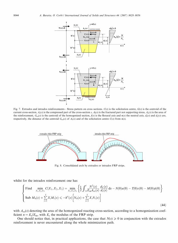
Fig. 7. Extrados and intrados reinforcements - Stress pattern on cross sections. C(s) is the solicitation centre, G(s) is the centroid of thecurrent cross-section, Ar(s) is the compressed part of the cross-section s, Af(s) is the fractured part not supporting stress, Ac(s) is the area ofthe reinforcement, Gro(s) is the centroid of the homogenized section, f(s) is the flexural axis and n(s) the neutral axis, dr(s) and dC(s) are,respectively, the distance of the centroid Gro(s) of Ar(s) and of the solicitation centre C(s) from n(s).
extrados thin FRP strip intrados thin FRP strip
Fig. 8. Consolidated arch by extrados or intrados FRP strips.
8044 A. Baratta, O. Corbi / International Journal of Solids and Structures 44 (2007) 8028–8056
whilst for the intrados reinforcement one has
Find minX 1;X 2;X 3
CðX 1;X 2;X 3Þ ¼ minX 1;X 2;X 3
12
R ‘
0
N 2ðsÞEmAroðsÞ
dCðsÞdrðsÞ ds� Nð0Þuð0Þ � Tð0Þvð0Þ �Mð0Þ/ð0Þ
�
Sub M0ðsÞ þP3i¼1
X iMiðsÞ 6 �h00ðsÞ N 0ðsÞ þP3i¼1
X iNiðsÞ� �
8>>><>>>:
ð44Þ
with Aro(s) denoting the area of the homogenized reacting cross-section, according to a homogenization coef-ficient n = Ec/Em, with Ec the modulus of the FRP strip.One should notice that, in practical applications, the case that N(s) P 0 in conjunction with the extradosreinforcement is never encountered along the whole minimization path.
A. Baratta, O. Corbi / International Journal of Solids and Structures 44 (2007) 8028–8056 8045
5.2. Limit Analysis: the static approach
Because of the change in the constraint conditions one has, for extrados reinforcement,
Fig. 9.work.
Find maxk;X 1;...;X 4
fkg
sub fk½M0ðsÞ þ N 0ðsÞh0ðsÞ� þX3
j¼1
X j½MjðsÞ þ h0ðsÞNjðsÞ� 6 �½ �M0ðsÞ þ �N 0ðsÞh0ðsÞ� 8s 2 ð0; ‘Þ ð45Þ
whilst, for intrados reinforcement
Find maxk;X 1;...;X 4
fkg
sub f�k½M0ðsÞ � N 0ðsÞh00ðsÞ� �X3
j¼1
X j½MjðsÞ � h00ðsÞNjðsÞ� 6 ½ �M0ðsÞ � �N 0ðsÞh00ðsÞ� 8s 2 ð0; ‘Þ ð46Þ
5.3. Duality in linear programming: the kinetic approach as the dual problem of the static approach
Again duality may be successfully applied, in a form analogous to what shown in the above, to the prob-lems Eqs. (45) and (46), in order to check, also in case of FRP reinforcement, the relationship between thestatic and kinetic approaches by means of duality (Baratta and Corbi, 2003g, 2004).
In the case of reinforcement, one should distinguish between the R calculus sections:
(i) sections without reinforcement, denoted by r�i ði ¼ 1; . . . ;R�Þ,(ii) sections with extrados reinforcement, denoted by �riði ¼ 1; . . . ; �RÞ,
(iii) sections with intrados reinforcement, denoted by ri (i = 1, . . . ,R),(iv) sections with reinforcement both at the intrados and at the extrados.
with Rþ �Rþ R� ¼ R.
M
MN
N
Element at cross-section "r"
cross-section "r"
fracture
δφ 'r
B
h'r
h"r
AFRP strip
0;y;0u r2rr =φ ′′δ=φ′δ=δrA hNMM ′+=
M
MN
N
Cross section "r"
fracture
Ah'r
h"r
B
FRP strip
rB hNMM ′′−=
3rrr y;0;0u −=φ ′′δ=φ′δ=δ
δφ "r
A
B
M
MN
N
Element at cross-section "r"
cross-section "r"
fracture
δφ 'r
B
h'r
h"r
AFRP strip
0;y;0u r2rr =φ ′′δ=φ′δ=δ 0;y;0u r2rr =φ ′′δ=φ′δ=δrA hNMM ′+=rA hNMM ′+=
M
MN
N
Cross section "r"
fracture
Ah'r
h"r
B
FRP strip
rB hNMM ′′−=rB hNMM ′′−=
3rrr y;0;0u −=φ ′′δ=φ′δ=δ 3rrr y;0;0u −=φ ′′δ=φ′δ=δ
δφ "r
A
B
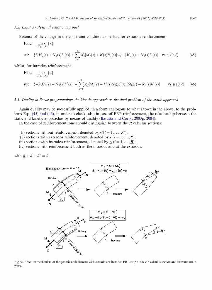
Fracture mechanism of the generic arch element with extrados or intrados FRP strip at the rth calculus section and relevant strain

8046 A. Baratta, O. Corbi / International Journal of Solids and Structures 44 (2007) 8028–8056
Let consider the fracture modes of the generic element on the arch or on the pile shown in Fig. 9, respec-tively, for the extrados and intrados reinforcements; one can recognize in yr with r = 1, . . . ,R the mechanismsrelevant to the R calculus sections, which are linked by compatibility conditions for composing the overallstructure mechanism y.
6. Numerical and experimental results
6.1. Reinforcement of the masonry vault by means of FRP short strips
For producing preliminary numerical results (Baratta and Corbi, 2001a,b, 2003d), one refers to the portalarch frame model depicted in Fig. 10 and adopted for experimental tests in (Briccoli and Rovero, 2000), withgeometric parameters L = 1.50 m, f = 0.43 m, d = 0.10 m, h = 0.20 m, b = 1 m. The masonry is characterizedby unit weight c = 18,000 N m�3 and Young modulus Ec = 1785 MPa; the limit tension in compression isr000 ¼ 17:4 MPa for the brick element and r000 ¼ 7:8 MPa for the mortar, and it is assumed equal to the smallestvalue, for the whole. The arch depth is 0.10 m, whilst the two abutments are 1 m thick. The discretizationadopts 72 element; the abutments are considered not-deformable since they are very short and massive.
The model is assumed to be subject to its own weight, represented by a distributed load, and to the lumpedforce r acting at the arcade keystone (Fig. 10). By increasing the lumped surface force r, applied on the twokeystone elements, the structure firstly becomes iso-static by formation of three hinges (one at the keystone onthe extrados and two at the reins on the intrados), and then it turns into a collapse mechanism by the furtheractivation of two extrados hinges at the springers. The collapse condition is reached at r = 450 N.
In order to increase the structure loading capacity, some FRP reinforcements can be inserted, for example,at the intrados, preventing the activation of the keystone extrados hinge.
In the numerical investigation some Mac Brace C1-30 strips of variable length s*, as thick as the arch itself(0.10 m), are applied at the intrados keystone symmetrically with respect to the y-axis.
The first problem in FRP reinforcement of arcades, especially when it is glued at the intrados of the arch, isthat when the strip is stressed in tension, it tends to loose the adhesion to masonry; tensile stresses are gener-ated between the FRP surface and the intrados surface, due to the strip curvature that follows, of course, theprofile of the arch. On the subject, it is necessary to keep under control the debonding stress that tends todetach the strip from masonry (Baratta and Corbi, 2001a,b).
The FRP strips are characterized by limit values rf,o = 3430 MPa, rad,o = 0.44 MPa, respectively, the limitand adhesion stress, and by a Young modulus EFRP = 230000 MPa.
By looking at results reported in Fig. 11, relevant to two lengths of FRP strips (covering, respectively, two,s* = 0.05 m, or 72, s* = 1.80 m, arch elements), one can appreciate (Baratta and Corbi, 2003d) the efficiency ofthe applied reinforcements: actually the adoption of the shortest considered FRP strip already results almostin doubling the original loading capacity of the arch, which now reaches the failure at 900 N.
When adopting the FRP strip 1.80 m long no collapse mechanism is activated and the failure is due to thecrushing in compression of the masonry. The limit adhesion stress is not attained in any case.
Fig. 10. The masonry arch model.

Fig. 11. Maximum absolute values of keystone displacement, maxjvj, and masonry compressive stress, maxjrj, for the reinforced arch.
A. Baratta, O. Corbi / International Journal of Solids and Structures 44 (2007) 8028–8056 8047
The numerical model is also compared with the results deriving from the laboratory tests by (Briccoli andRovero, 2000); in this case one refers to the arch model reinforced by small FRP provisions, suitablylocated at positions where cracks occurred during the first load program on the not-reinforced arch (twoextrados FRP strips at reins and an intrados strip at keystone): theoretical results (Fig. 12) are shown toindividuate a collapse load somewhat larger than the one in the experiments. The difference is probablydue to the adhesion strength of the FRP strips, which is assumed unbounded in the theoretical treatment.From the experimental curve one can thus deduce the ‘‘limit’’ value of the adhesion stress rad,o, which isattained when rad = rad,o and is responsible of the crisis because of the debonding of the FRP strip fromthe masonry. Actually rad,o cannot be directly inferred from the experimental r–vexp diagram, but it requiresa kind of back-analysis, which, after identifying its value on the theoretical rad–v curve, allows for itsapproximate evaluation.
In Fig. 12 one can notice that all of the diagrams do not start from the condition (0,0): this is due to theinitial deformation of the portal arch produced by its own weight, before the lumped force starts to increase.
6.2. Reinforcement of the masonry vault by means of continuous FRP strips
6.2.1. Experimental campaign
In order to evaluate the benefits induced on a traditional masonry portal arch by the application of con-tinuous carbon fibre strips, experimental tests have been developed at the Laboratory of Materials and Struc-tural Testing of the University of Naples ‘‘Federico II’’.
The geometry of the portal arch (Fig. 13) is symmetrical and is characterized by span L = 1900 mm, risef = 660 mm, arch thickness d = 240 mm, piles thickness b = 385 mm, piles height h = 1700 mm; the arch shapeis a semi-ellipse. The arch depth is 400 mm, whilst the two abutments are 480 mm deep.
The masonry is characterized by unit weight c = 12,300 N m�3 and Young modulus E = 5.5 GPa.In the second stage of the experimental campaign one also considers some FRP continuous reinforcement
applied on the arch length.In this case, the FRP reinforcements consist of continuous mono-directional FRP strips applied on the
extrados or on the intrados of the arch, respectively.The adopted reinforcement, produced by FTS, is a BETONTEX system GV330 U-HT, made of 12 K car-
bon fibre, jointed by an ultra light net of thermo-welded glass.The mechanical characteristics of the employed carbon fibres are: tensile limit stress rFRP = 4.89 GPa, elas-
tic modulus in traction EFRP = 244 GPa, limit elongation eFRP = 2%. The FRP strip is characterized by thick-ness of 0.177 mm and depth of 100 mm.

0.2
σad(MPa)
r(N)
σad
vnum
v exp
σad = σad,oattained
σad,o
0.0
0.1
0.2
0.3
0.4
0.5
0.6
0.7
v (m)0.020 0.04 0.06 0.08 0.1 0.12 0.14 0.16 0.18
σadσad(MPa)
r(N)
σadσad
vnumvnum
v expv exp
σad = σad,oattained
σad,o
0
200
400
600
800
1000
1200
1400
Fig. 12. Numerical (vnum, rad) versus experimental (vexp) results.
FG1
I1
E1
d15
d14
d13
d12d11
d10 d9 d8 d7d6
d5
d4
d3
d2d16d17
d18
d19
d20
d21d23 d24 d25 d26
d27d28
d29
d22
d1d30T1 T2 Dial Gauge G1
Inclinometer I1
Transducers T1,T2
Extesemeter E1
Deformometric cells dk, k=1…30
FG1
I1
E1
d15
d14
d13
d12d11
d10 d9 d8 d7d6
d5
d4
d3
d2d16d17
d18
d19
d20
d21d23 d24 d25 d26
d27d28
d29
d22
d1d30T1 T2 Dial Gauge G1
Inclinometer I1
Transducers T1,T2
Extesemeter E1
Deformometric cells dk, k=1…30
Dial Gauge G1
Inclinometer I1
Transducers T1,T2
Extesemeter E1
Deformometric cells dk, k=1…30
1
Inclinometer I1
Transducers T1,T2
Extesemeter E1
Deformometric cells dk, k=1…30
INCLINOMETER I1
DEFORMOMETER CELLS d9, d11,d22
LOAD CELL
DIAL GAUGE G1
EXTENSOMETER E1
TRANSDUCERS T1,T2
INCLINOMETER I1
DEFORMOMETER CELLS d9, d11,d22
LOAD CELL
DIAL GAUGE G1
EXTENSOMETER E1
TRANSDUCERS T1,T2
a b
Fig. 13. The portal arch model with the monitoring equipment: (a) sketch of monitoring equipment; (b) picture from laboratory tests.
8048 A. Baratta, O. Corbi / International Journal of Solids and Structures 44 (2007) 8028–8056
After roughly preparing the masonry support in order to render the application surface smoother, the FRPreinforcement is directly laminated on the masonry, at the same time with the impregnation of the fibres bymeans of a special bi-component epoxy resin.
As regards the execution of the tests, the structure is subject to its constant own weight and to a lumpedhorizontal force F, applied on the top right side of the right abutment in the rightward direction in the increas-ing phase (Fig. 13), which is transmitted by means of a loading equipment consisting of a load cell placed onthe right side of the portal arch. This force is able to potentially produce collapse of the structure according toa mechanism that is typical of earthquake failures of arch-portals (Fig. 20b), and it is intended to represent apseudo-seismic action, able to yield a measure of the structure attitude to sustain earthquake shaking.
The monitoring equipment consists of:
– 1 dial gauge G1, placed on the left side of the left abutment, finalized to the monitoring of the absolutedisplacement of the pile;
– 2 transducers T1 and T2, vertically placed on the front side of the left abutment, finalized to the monitor-ing of the length variation of both edges of the pile;

A. Baratta, O. Corbi / International Journal of Solids and Structures 44 (2007) 8028–8056 8049
– 1 inclinometer I1, placed on the top of the left abutment, finalized to the monitoring of the pile averagerotation;
– 1 extensometer E1, placed between the two abutments, finalized to the monitoring of the relative piles’drift;
– 30 deformometer cells, placed on the front of the arch, finalized to the monitoring of the arcadedeformation.
In the first loading cycle, the structure firstly becomes isostatic by formation of three hinges: one at the key-stone on the extrados and two at the reins on the intrados. The increase of the horizontal force turns the struc-ture into a collapse mechanism by the further activation of a hinge at the bottom of the right side of the rightpile (Baratta and Corbi, 2005).
Therefore the critical condition is related to the activation of a collapse mechanism composed by fourhinges.
The hinges are distributed as follows:
– 1 at the keystone on the extrados,– 2 at the reins on the intrados,– 1 at the bottom of the right pile on the extrados.
The collapse condition is reached at F � 80 N; the low failure value of the force shows that, due to the cho-sen elliptical shape of the arch, the funicular line compatible with the applied loads and admissible (i.e. interiorto the arch profile) is already very close to the upper and lower bounds of the arch profile at the rest condition.
In Fig. 14a one can follow the whole fracture path relevant to the arch during the loading process by meansof the deformometer cells placed on the arch; the distance variation between the couples of adjacent cells isreported in mm 10�1 for increasing values of the load F in Newtons, and is to be read with respect to the ver-tical fundamental line relevant to the considered couple.
One can immediately appreciate the opening of the keystone fracture by looking at the deformometer cellsd22–d23, while the fractures at the left and right reins can be appreciated by observing the cells d12–d13 and d4–d5, respectively.
Fig. 14b reports the diagram relevant to the absolute rotation of the left abutment, read by means of theinclinometer I1, versus the horizontal load. A picture at the first stage when the keystone crack is formed isreported in Fig. 15a.
After reaching the collapse condition, the portal arch is then unloaded in order to be prepared for the sub-sequent experimental tests on FRP reinforcements, which are reported in the following sections.
0
0 ,1
0 ,2
0 ,3
0 ,4
0 ,5
0 ,6
0 ,7
0 ,8
0 ,9
10
9
8
7
6
5
4
3
2
1
0
Inclinometer I1
100
90
80
70
60
50
40
30
20
10
0
0 1 2 3 4 5 6 7 8 9 10 11 12 1 3 14 1 5 1 6 17 18 19 20 21 22 23 2 4
m illim et ri
d3-d4 d5-d6 d7-d8 d9-d10 d11-d12 d13-d14 d17-d18 d20-d21 d22-d23 d24-d25 d27-d28
deformometer cells (mm·10-1)
hinge d4-d5 hinge d12-d13 hinge d22-d23
10 mm
d1-d2 d4-d5 d6-d7 d8-d9 d10-d11 d12-d13 d15-d16 d19-d20 d21-d22 d23-d24 d26-d27 d29-d30
0
0 ,1
0 ,2
0 ,3
0 ,4
0 ,5
0 ,6
0 ,7
0 ,8
0 ,9
10
9
8
7
6
5
4
3
2
1
0
Inclinometer I1
100
90
80
70
60
50
40
30
20
10
00
0 ,1
0 ,2
0 ,3
0 ,4
0 ,5
0 ,6
0 ,7
0 ,8
0 ,9
10
9
8
7
6
5
4
3
2
1
0
abs rotation (˚)0 0.5 1
Inclinometer I1
100
90
80
70
60
50
40
30
20
10
0
0 1 2 3 4 5 6 7 8 9 10 11 12 1 3 14 1 5 1 6 17 18 19 20 21 22 23 2 4
m illim et ri
d3-d4 d5-d6 d7-d8 d9-d10 d11-d12 d13-d14 d17-d18 d20-d21 d22-d23 d24-d25 d27-d28
deformometer cells (mm·10-1)
hinge d4-d5 hinge d12-d13 hinge d22-d23
10 mm
d1-d2 d4-d5 d6-d7 d8-d9 d10-d11 d12-d13 d15-d16 d19-d20 d21-d22 d23-d24 d26-d27 d29-d300 1 2 3 4 5 6 7 8 9 10 11 12 1 3 14 1 5 1 6 17 18 19 20 21 22 23 2 4
m illim et ri
100
90
80
70
60
50
40
30
20
10
0
forc
e (N
)
d3-d4 d5-d6 d7-d8 d9-d d11-d12 d13-d14 d17-d18 d20-d21 d22-d23 d24-d25 d27-d28
deformometer cells (mm·10-1)
hinge d4-d5hinge d4-d5hinge d4-d5 hinge d12-d13 hinge d12-d13 hinge d12-d13 hinge d22-d23hinge d22-d23hinge d22-d23
10 mm10 mm
d1-d2 d4-d5 d6-d7 d8-d9 d10-d11 d12-d13 d15-d16 d19-d20 d21-d22 d23-d24 d26-d27 d29-d30
a b
Fig. 14. Unreinforced portal arch: (a) Distance variation of the deformometer cells (mm 10�1); (b) absolute rotation (�) of the leftabutment versus the horizontal force (N) for the portal arch.

Fig. 15. Details of the portal arch during the experimental tests: (a) without reinforcement; (b) with intrados FRP reinforcement.
8050 A. Baratta, O. Corbi / International Journal of Solids and Structures 44 (2007) 8028–8056
After completing the unloading process, the portal arch is prepared for laboratory tests on FRP reinforce-ments, which are finalized to the evaluation of the benefits induced on the model response by the applicationof carbon fibre strips.
The first application, shown in Figs. 15b and 16, consists of a continuous FRP strip bonded on the extradosof the arch. Since the collapse mechanism of the not reinforced simple portal arch is characterized, asdescribed in the above, by the formation of two intrados hinges at the reins of the arch, corresponding tothe fractures d4–d5 and d12–d13 at the extrados, the major effect of this intervention is supposed to be the pre-vention of these fractures, and, therefore, a wide increase in the model loading capacity.
The funicular line is now free to exceed the lower contour of the portal arch cross-section.The arch deformation path can be appreciated by looking at Fig. 16.As expected, the activation of the two old fractures d4–d5 and d12–d13 at the extrados is now prevented,
while only a reduction of the opening of the old fracture d22–d23 at the arch intrados is produced.The failure, in this case, is due to the activation of a collapse mechanism and, simultaneously, to the shear
of the right abutment (d1–d2), which produces a localized fracture in the masonry at the location where theload is applied.
The distance variation between the couples of adjacent deformometer cells (to be read with respect to thevertical fundamental line relevant to the considered couple) versus the horizontal load in Fig. 16a offers a clearreading of the repair of the old fractures d4–d5 and d12–d13 and of the activation of the fracture d1–d2.
0
1
2
3
4
5
6
7
8
9
10
0 1 2 3 4 5 6 7 8 9 10 11 12 13 14 15 16 17 18 19 20 21 22 23 24deformometers (mm)
forc
e (N
)
1000
900
800
700
600
500
400
300
200
100
0 d3-d4 d5-d6 d7-d8 d9-d10 d11-d12 d13-d14 d17-d18 d20-d21 d22-d23 d24-d25 d27-d28
deformometer cells (mm·10-1)
d22-d23 d12-d13 d4-d5
shear fracture d1-d2
10 mm
d1-d2 d4-d5 d6-d7 d8-d9 d10-d11 d12-d13 d15-d16 d19-d20 d21-d22 d23-d24 d26-d27 d29-d30
0
1
2
3
4
5
6
7
8
9
10
0 0,5 1g ra d i
Inclinometer I1
1000
900
800
700
600
500
400
300
200
100
0
abs rotation (˚)0 0.5 1
0
1
2
3
4
5
6
7
8
9
10
0 1 2 3 4 5 6 7 8 9 10 11 12 13 14 15 16 17 18 19 20 21 22 23 24deformometers (mm)
forc
e (N
)
1000
900
800
700
600
500
400
300
200
100
0 d3-d4 d5-d6 d7-d8 d9-d10 d11-d12 d13-d14 d17-d18 d20-d21 d22-d23 d24-d25 d27-d28
deformometer cells (mm·10-1)
d22-d23 d12-d13 d4-d5
shear fracture d1-d2
10 mm
d1-d2 d4-d5 d6-d7 d8-d9 d10-d11 d12-d13 d15-d16 d19-d20 d21-d22 d23-d24 d26-d27 d29-d30
0
1
2
3
4
5
6
7
8
9
10
0 1 2 3 4 5 6 7 8 9 10 11 12 13 14 15 16 17 18 19 20 21 22 23 24deformometers (mm)
forc
e (N
)
1000
900
800
700
600
500
400
300
200
100
0
forc
e (N
)
d3-d4 d5-d6 d7-d8 d9-d10 d11-d12 d13-d14 d17-d18 d20-d21 d22-d23 d24-d25 d27-d28
deformometer cells (mm·10-1)
d22-d23 d22-d23 d22-d23 d12-d13 d12-d13 d12-d13 d4-d5d4-d5d4-d5
shear fracture d1-d2shear fracture d1-d2
10 mm10 mm
d1-d2 d4-d5 d6-d7 d8-d9 d10-d11 d12-d13 d15-d16 d19-d d -d d -d d -d d -d
0
1
2
3
4
5
6
7
8
9
10
0 0,5 1g ra d i
Inclinometer I1
1000
900
800
700
600
500
400
300
200
100
0
abs rotation (˚)0 0.5 1
0
1
2
3
4
5
6
7
8
9
10
0 0,5 1g ra d i
Inclinometer I1
1000
900
800
700
600
500
400
300
200
100
00
1
2
3
4
5
6
7
8
9
10
0 0,5 1g ra d i
Inclinometer I1
1000
900
800
700
600
500
400
300
200
100
0
abs rotation (˚)0 0.5 1a
b
Fig. 16. Portal arch with extrados FRP strip: (a) Distance variation of the deformometer cells (mm 10�1); (b) absolute rotation (�) of theleft abutment versus the horizontal force (N).

A. Baratta, O. Corbi / International Journal of Solids and Structures 44 (2007) 8028–8056 8051
Therefore the critical condition is related to the activation of a collapse mechanism composed by fourhinges, distributed as follows:
– 1 at the top of the left pile on the intrados,– 1 at the keystone on the extrados,– 1 under the load cell on the intrados of the right pile (where shear occurs)– 1 at the bottom of the right pile on the extrados.
The collapse is reached at F � 800 N with an increase in the loading capacity of the portal arch of approx-imately 10 times with respect to the unconsolidated case.
Fig. 16b reports the diagram relevant to the absolute rotation of the left abutment, read by means of theinclinometer I1 versus the horizontal load.
After unloading the repaired portal arch, the first FRP provision is removed and the model is prepared forthe second FRP retrofit, which is shown in the following section.
The second intervention test for retrofitting the damaged portal arch, which is shown in Fig. 17, consists ofapplying a continuous FRP strip at the intrados of the arch. The strip covers the whole length of the arch andan upper part of the abutments almost equal to the thickness of two bricks; this provision is expected to pre-vent the activation of the keystone extrados hinge, corresponding to the fracture d22–d23 on the simple uncon-solidated arch.
The funicular line is now free to exceed the upper profile of the portal arch cross-section.In Fig. 18a one can follow the whole fracture path relevant to the arch during the loading process by means
of the deformometer cells placed on the arch; the distance variation between the couples of adjacent cells is tobe read with respect to the vertical fundamental line relevant to the considered couple.
As expected, the fracture d22–d23 is completely repaired, while nothing can be done as regards to the twofractures d4–d5 and d12–d13 at the extrados, since the reinforcement is applied on the arch intrados.
During the loading, one can notice the activation of two hinges at the right side bottom and at the left sidetop of the right abutment, which are due to the rotation of the right pile that behaves like a joint block(Fig. 17); the second hinge produces the fracture d1–d2 in Fig. 18a on the opposite side of the abutment.
For understanding the overall behaviour one can still refer to Fig. 13a, in order to locate the mentionedcross-sections.
At the same time, with regards to the fractures d4–d5 and d12–d13 originally activated at the extrados of theunconsolidated arch, one can observe that d4–d5 tends to open, and its cross section (line from extrados pointd4–d5 to opposite intrados point d26–d27) starts to slide in the rightward direction; in the meanwhile fractured12–d13 tends to close, according to the sketch in Fig. 19.
Fig. 17. Details of the portal arch reinforced with intrados C-fibre strip during the experimental tests.

0
2
4
6
8
10
12
14
16
18
0 1 2 3 4 5 6 7 8 9 10 11 12 13 14 15 16 17 18 19 20 21 22 23 24 25
millimet ri
Fo
rza
d3-d4 d5-d6 d7-d8 d9-d10 d11-d12 d13-d14 d17-d18 d20-d21 d22-d23 d24-d25 d26-d27 d29-d30
deformometer cells (mm·10-1)
10 mm
d1-d2 d4-d5 d6-d7 d8-d9 d10-d11 d12-d13 d15-d16 d19-d20 d21-d22 d23-d24 d25-d26 d27-d28
d4-d5 d12-d13
hinge d1-d2
d22-d23
FRP detachment d26-d27
forc
e (N
)1800
1600
1400
1200
1000
800
600
400
200
0 0
2
4
6
8
10
12
14
16
18
Inclinometer I1
abs rotation (˚)0 1 2
1800
1600
1400
1200
1000
800
600
400
200
00
2
4
6
8
10
12
14
16
18
0 1 2 3 4 5 6 7 8 9 10 11 12 13 14 15 16 17 18 19 20 21 22 23 24 25
millimet ri
Fo
rza
d3-d4 d5-d6 d7-d8 d9-d10 d11-d12 d13-d14 d17-d18 d20-d21 d22-d23 d24-d25 d26-d27 d29-d30
deformometer cells (mm·10-1)
10 mm
d1-d2 d4-d5 d6-d7 d8-d9 d10-d11 d12-d13 d15-d16 d19-d20 d21-d22 d23-d24 d25-d26 d27-d28
d4-d5 d12-d13
hinge d1-d2
d22-d23
FRP detachment d26-d27
forc
e (N
)1800
1600
1400
1200
1000
800
600
400
200
00
2
4
6
8
10
12
14
16
18
0 1 2 3 4 5 6 7 8 9 10 11 12 13 14 15 16 17 18 19 20 21 22 23 24 25
millimet ri
Fo
rza
d3-d4 d5-d6 d7-d8 d9-d10 d11 12 d13-d14 d17- d 18 d20-d21 d22-d23 d24-d25 d26-d27 d29-d30
deformometer cells (mm·10-1)
10 mm10 mm
d1-d2 d4-d5 d6-d7 d8-d9 d10-d11 d12-d13 d15-d16 d19-d20 d21-d22 d23-d24 d25-d26 d27-d28
d4-d5d4-d5d4-d5 d12-d13d12-d13d12-d13
hinge d1-d2hinge d1-d2
d22-d23d22-d23
FRP detachment d26-d27FRP detachment d26-d27
forc
e (N
)
1800
1600
1400
1200
1000
800
600
400
200
0 0
2
4
6
8
10
12
14
16
18
Inclinometer I1
1800
1600
1400
1200
1000
800
600
400
200
00
2
4
6
8
10
12
14
16
18
Inclinometer I1
1800
1600
1400
1200
1000
800
600
400
200
0
a b
Fig. 18. Portal arch with intrados FRP strip: (a) Distance variation of the deformometer cells (mm 10�1); (b) absolute rotation (�) of theleft abutment versus the horizontal force (N).
FRP strip
Unilateralhinges
Detachmentarea
Undeformed configuration
Deformed configuration
Raising-up of the pile edge
Sliding
Fig. 19. Portal arch with intrados FRP strip: local detachment of the strip and sliding.
8052 A. Baratta, O. Corbi / International Journal of Solids and Structures 44 (2007) 8028–8056
At F � 1300 N, a local detachment of the FRP strip from the arch occurs at the location d26–d27, whichcorresponds to the sliding crack related to the original fracture d4–d5 on the opposite side of the arch. Thisphenomenon, which is pointed out by the jump in the diagram d26–d27 in Fig. 18a, is an anomaly with respectto the unilateral hinge fracture pattern, which, anyway, does not significantly influence the overall behaviourof the structure.
The structure is now locally damaged but further sliding is halted after the initial movement because of fric-tion coupled with the lumping of the arch weight on the rightward buttress, and some strength reserve can bestill attained.
By further increasing the load, two other hinges are activated at the right side bottom and at the left sidetop of the left abutment, transforming the structure in a collapse mechanism.
It is interesting to observe that, since the FRP strip covers the upper intrados part (for almost two bricks) ofthe abutments, the hinges at the top left sides of the piles are located at an height immediately below the end ofthe FRP strip.
Therefore the critical condition is related to the activation of a collapse mechanism composed by fourhinges.

A. Baratta, O. Corbi / International Journal of Solids and Structures 44 (2007) 8028–8056 8053
The hinges are distributed as follows:
– 1 at the bottom of the left pile on the intrados,– 1 at the top of the left pile on the extrados,– 1 at the top of the right pile on the intrados,– 1 at the bottom of the right pile on the extrados.
The collapse condition is reached at F � 1600 N, and corresponds to the failure of the structure.Fig. 18b reports the diagram relevant to the absolute rotation of the left abutment, read by means of the
inclinometer I1, versus the horizontal load.
6.2.2. Experimental/numerical agreementNumerical investigation on the portal arch model experimentally tested results in the possibility of appre-
ciating the skill of the NRT model to capture the major features of the structure behaviour. Moreover also thecorrect modelling of the reinforcement and of its coupling with the main structure can be evaluated.
One reports in Fig. 20a a numerical/experimental comparison relevant to the right pile top displacement u
(mm) versus the varying load F (N) for the un-reinforced arch.One can observe a pretty good agreement between the numerical and experimental data. The calculus code,
implementing the above reported theoretics, which has been developed by the authors as all other codesadopted for numerical investigation, is demonstrated to be able to capture the behaviour of the portal archfollowing the whole loading path up to collapse; Fig. 20b depicts the collapse mechanism of the structure,clearly due to the formation of four hinges: one at the keystone on the extrados, two at the reins on the intra-dos, one at the bottom of the right pile on the extrados.
Moreover one reports in Fig. 21a a numerical/experimental comparison relevant to the right pile top dis-placement u (mm) versus the varying load F (N) for the arch reinforced with an extrados FRP reinforcement.
Again one can observe a pretty good agreement between the numerical and experimental data. The calculuscode, implementing the above reported theoretics, again ad-hoc produced by the authors, is demonstrated to beable to capture the behaviour of the portal arch; Fig. 21b depicts the collapse mechanism of the structure, clearlydue to the formation of four hinges: one at the top of the left pile on the intrados, one at the keystone on the extra-dos, one under the load cell on the intrados of the right pile, one at the bottom of the right pile on the extrados.
Both numerical and experimental data agree in assessing at approximately ten times the original value theincrement of the loading capacity of the structure due to the extrados FRP reinforcement.
0 20 40 60 80 100
0
2
4
6
8
10 u (mm)
F (N)
Experimental Data
NumericalData
Trend Line
a b
Fig. 20. Unreinforced portal arch: (a) pile displacement u versus load F – numerical/experimental comparison; (b) picture of the collapsemechanism captured from the calculus code.

0 200 400 600 800 1000
0
2
4
6
8
10 u (mm)
F (N)
Experimental Data
NumericalData
Trend Line
a b
Fig. 21. Portal arch with extrados reinforcement: (a) pile displacement u versus load F – numerical/experimental comparison; (b) pictureof the collapse mechanism captured from the calculus code.
0 400 800 1200 1600 20000
10
20
30
40 u (mm)
F (N)
Experimental Data
Trend Line
Numerical Data
Fig. 22. Portal arch with intrados reinforcement: pile displacement u versus load F – numerical/experimental comparison.
8054 A. Baratta, O. Corbi / International Journal of Solids and Structures 44 (2007) 8028–8056
Finally, a good agreement between the numerical and experimental data can be appreciated also for thecase of intrados reinforcement; relevant results are illustrated in Fig. 22, where a numerical/experimental com-parison relevant to the right pile top displacement u (mm) versus the varying load F (N) is reported.
7. Conclusions
In the paper one gives an overall guideline for approaching the study of masonry structures, with specialreference to vaults, deepening both theoretical, numerical and experimental features. Moreover, one also con-siders the case of reinforcing masonry vaults by gluing some FRP strips at prefixed locations to the main struc-ture, in order to evaluate the best intervention to be adopted and the benefits induced against seismic hazard.
The theoretical set up of the relevant problems are shown to work very well and sharply fit experimentalresults as well as engineering expectation of masonry structures in general (see e.g. Baratta, 1996).
With particular reference to FRP reinforcement, theory and experiments in the paper prove that:
i. The FRP reinforcement has a very significant effect on pseudo-seismic strength of arcades.ii. The effect may be an increase of the strength up to 10 times the original one for extrados application and
up to 20 times for intrados reinforcement.

A. Baratta, O. Corbi / International Journal of Solids and Structures 44 (2007) 8028–8056 8055
iii. In the case of extrados application, the behaviour is highly ductile and collapse is due to loss of stabilityafter large displacements have been produced.
iv. In the case of intrados application, after ductility is exhausted the collapse occurs suddenly due to deb-onding of the FRP strip.
v. It is expected that further improvement can be attained if adhesion of FRP to masonry is improved, pos-sibly by the application of suitable connectors.
vi. Mechanical models based on no-tension behaviour of masonry and linearly elastic behaviour of FRPstrips have been developed.
vii. The analysis allows to calculate stress, strain and displacements, and to control the adhesion stressbetween FRP strips and masonry.
viii. The theoretical results are in excellent agreement with experiments.
The investigation definitively proves the reliability of the model and the effectiveness of the adopted FRPreinforcements, which are able to deeply increase the carrying capacity of the structure. Actually the very goodagreement of the results deriving from the implementation of the proposed theoretical approach with the datarelevant to the laboratory experimentation definitely validates the present no-tension approach as a veryappropriate tool to check and certificate safety improvement after reinforcement. This definitely representsa very encouraging and fully satisfying result.
Acknowledgements
Paper contributed by grants of MIUR (Italian Ministry of University and Research). The cooperation ofthe technicians of the Laboratory of the Department of Structural Mechanics ‘‘Vincenzo Franciosi’’ is grate-fully acknowledged by the authors.
References
Baratta, A., 1984. Il Materiale Non Reagente a Trazione Come Modello per il Calcolo delle Tensioni nelle Pareti Murarie’’. Giornale diRestauro 75, 53–77.
Baratta, A., 1991. Statics and reliability of masonry structures. In: General Principles Applications in Mechanics of Solids and Structures.CISM, Udine, pp. 205–235.
Baratta, A., 1996. Structural analysis of masonry buildings. In: Baratta, A., Colletta, T. (Eds.), Seismic Risk of Historic Centers. APreliminary Approach to the Naples Case. La Citta del Sole B.C., Napoli, pp. 76–122.
Baratta, A., Corbi, O., 2001a. No-tension masonry model for FRP reinforcement assessment. In: Hughes, T.G., Pande, G.N. (Eds.),Computer Methods in Structural Masonry. Computers & Geotechnics Ltd., Swansea, ISBN: 0 9510380 28.
Baratta, A., Corbi, O., 2001b. Masonry arches refurbishment by fibers reinforced polymers. In: Proc. 3rd International Conference onArch Bridges, Parigi, 2001.
Baratta, A., Corbi, O., 2003a. On variational approaches to NRT continua. International Journal of Solids and Structures 42, 5307–5321.Baratta, A., Corbi, O., 2003b. Limit Analysis of No Tension Bodies and Non-Linear Programming. In: Proc. 9th Int. Conf. Civil and
Structural Engineering Computing. Egmond Aan Zee, Netherlands.Baratta, A., Corbi, O., 2003c. Programmazione Lineare ed Analisi Limite di Strutture ad Arco Fibrorinforzate. In: Proc. 32nd Nat. Cong.
AIAS, Salerno, Italy.Baratta, A., Corbi, O., 2003d. The No Tension Model for the Analysis of Masonry-Like Structures Strengthened by Fiber Reinforced
Polymers. International Journal of Masonry International, British Masonry Society 16 (3), 89–98.Baratta, A., Corbi, O., 2003e. On the evaluation of reinforcement effectiveness in masonry panels under vertical and horizontal loads.
International Journal of Earthquake Engineering and Engineering Seismology, Patron Editore, XVII (3), 27–35.Baratta, A., Corbi, O., 2003f. Valutazione dell’Efficacia delle Fibre di Carbonio nella Riparazione di Archi Murari: Confronto Numerico/
Sperimentale, XVI Nat. Cong. AIMETA, Ferrara, Italy.Baratta, A., Corbi, O., 2003g. Programmazione Lineare ed Analisi Limite di Strutture ad Arco Fibrorinforzate. In: Proc. XXXII Nat.
Cong. AIAS. Salerno, Italy. XXXII Convegno Nazionale.Baratta, A., Corbi, O., 2003h. Limit analysis of no tension bodies and non-linear programming. In: Topping, B.H.V. (Ed.), Civil and
Structural Engineering Computing. Civil-Comp Press, Glasgow, UK, p. 103, ISBN: 0-948749-89-X.Baratta, A., Corbi, O., 2004. Applicability of duality theory to L.A. Problems with undefined flow law. In: Proc. 1st Int. Conf. RRTEA on
Restoration, Recycling, Rejuvenation Technology for Engineering and Architecture Application. Cesena, Italy.Baratta, A., Corbi, O., 2005. Fibre Reinforced Composites in Civil Engineering. Experimental Validation of C-Fibre Masonry Retrofit.
International Journal of Masonry International, British Masonry Society 18 (3), 115–124.

8056 A. Baratta, O. Corbi / International Journal of Solids and Structures 44 (2007) 8028–8056
Baratta, A., Toscano, R., 1982. Stati Tensionali in Pannelli di Materiale Non Reagente a Trazione. In: Proc. 6th Nat. Conf. AIMETA,Genova.
Baratta, A., Voiello, G., 1987. Modelli Matematici per l’ Analisi delle Strutture Murarie. Giornale di Restauro 87/88, Napoli.Baratta, A., Vigo, M., Voiello, G., 1981. Calcolo di archi in materiale non resistente a trazione mediante il principio del minimo lavoro
complementare. In: Proc. 1st Nat. Conf. ASS.I.R.C.CO. Verona.Bazant, Z.P., 1995. Creep and damage in concrete. Journal of Materials Science of Concrete IV, 355–389.Bazant, Z.P., 1996. Analysis of work-of fracture method for measuring fracture energy of concrete. Journal of Engineering Mechanics
ASCE 122 (2), 138–144.Bazant, Z.P., 1997. Recent advances in brittle-plastic compression failure: damage localization, scaling and finite strain. In: Proceedings of
the 5th International Conference COMPLAS-5, Barcelona.Briccoli Bati, S., Rovero, L., 2000. Consolidamento di Archi in Muratura con Nastri di Composito a Fibre Lunghe di Carbonio (in
Italian). In: Nat. Conf. on Mechanics of Masonry Structures Strengthened with FRP-Materials, Venezia, 2000, pp. 53–64.Como, M., Grimaldi, A., 1983. A Unilateral model for limit analysis of masonry walls. In: Unilateral Problems in Structural Analysis,
Ravello, pp. 25–46.Del Piero, G., 1989. Constitutive equation and compatibility of the external loads for linear-elastic masonry materials. Giornale di
Meccanica 24, 150–162.Di Pasquale, S., 1982. Questioni di Meccanica dei Solidi Non Reagenti a Trazione. In: Proc. 6th Nat. Conf., vol. II, AIMETA, Genova,
pp. 251–263.Di Pasquale, S., 1984. Questioni Concernenti la Meccanica dei Mezzi Non Reagenti a Trazione. In: Proc. VII Nat. Conf. AIMETA,
Trieste, vol. V, pp. 227–238.El-Badry, M., 1996. Advanced Composite Materials Bridges and Structures. In: Proceedings of 2nd Int. Conf. Advanced Composite
Materials in Bridges and Structures, Montreal.Faza, S.S., Rhao, H.V.S., Barbero, E.J., 1994. In: H.A. Touranji (Ed.), Fiber Composite Wrap for Rehabilitation of Concrete Structures,
Repair and Rehabilitation of the Infrastructure of the Americas. The National Science Foundation, pp. 181–192.Franciosi, V., 1980. L’ attrito nel Calcolo a Rottura delle Murature (in Italian). Giorn. del Genio Civile 8, 215–234.Heyman, J., 1966. The stone skeleton. Journal of Solids and Structures 2, 269–279.Heyman, J., 1969. The Safety of Masonry Arches. Journal of Mechanical Engineering Science 2, 363–384 .Khludnev, A.M., Kovtunenko, V.A., 2000. Analysis of cracks in solids. Applied Mechanics Review 53 (10).Mangasarian, O.L., 1969. Nonlinear Programming. McGraw-Hill, USA.Rao, S.S., 1978. Optimization: Theory and Applications. Wiley & Sons, New Delhi.Schwegler, G., 1994. Masonry Construction Strengthened with Fiber Composites in Seismically Endangered Zones. In: Proceedings of
10th Eur.Conf. Earthquake Engineering, Vienna.Traintafillou, T.C., 1996. Innovative Strengthening of Masonry Monuments with Composites. In: Proc. 2nd Int. Conf. Advanced
Composite Materials in Bridges and Structures, Montreal.Weaver A., 1997. Composites towards the year 2000: opportunities and threats. In: Proc. Advancing with Composites, pp. 203–214.