strengthening of existing four lane flexible...
TRANSCRIPT

243 Rajkumari Joyshree Devi, Ngangbam Bulbul Singh, Pebam Rocky Singh,
Dr.Yendrembam Arunkumar Singh
International Journal of Engineering Technology Science and Research
IJETSR
www.ijetsr.com
ISSN 2394 – 3386
Volume 4, Issue 3
March 2017
STRENGTHENING OF EXISTING FOUR LANE FLEXIBLE
PAVEMENT ON NH 150 MALOM TO MOIRANG
LAMKHAI SECTION - A CASE STUDY
Rajkumari Joyshree Devi**
, Ngangbam Bulbul Singh**
, Pebam Rocky Singh*
Dr.Yendrembam Arunkumar Singh***
**M.Tech Student, Manipur Institute of Technology, Takyelpat, Manipur
*UG Student, Manipur Institute of Technology, Takyelpat , Manipur
***Assistant Professor, Manipur Institute of Technology ,Takyelpat, Manipur
ABSTRACT In this study, we have been considering the section of NH 150 from Malom to Moirang section, in the state of Manipur
for strengthening as the existing pavement has become inadequate for the increased traffic load and there is sign of
distress/failure in various locations on the stretches. The strengthening of the existing pavement to meet the requirements
of the traffic load & reconstruction of the road pavement in specific stretches where the sub grade has failed has been
taken care off. This paper includes the collection of required field data like soil subgrade data, structural study of the
existing flexible pavement, traffic data, pavement surface condition survey and rebound deflection by using Benkleman
Beam Deflection (BBD) technique, laboratory investigations and finally the design of the overall thickness of the road
pavement and overlay whatsoever required to strengthen the road stretches. The various deflections obtained from the
Benkelman beam are to be reduced to a characteristic deflection (in mm). The design of overlay is then obtained from the
design curves relating the characteristic pavement deflection to the cumulative number of standard axles to be carried
during the design life.
KEYWORDS :-BanklemanBeam Deflection, Overlay design, Distresses, Rebound deflection, Standard axle.
INTRODUCTION:-
Strengthening of pavement is the process of providing the required thickness of overlay on the existing
pavement so that it performs more effectively over a given design life under given dynamic and static loads,
once the pavement is evaluated for these loads prior to design. Pavements once constructed needs routine
maintenance for better performance. Strengthening of the flexible pavement by providing overlay is
commonly adopted as a cost effective measure. Even though there are many methods for designing of
overlays such as, Lacroix Deflectgraph, Dynaflect, Falling weight Deflectometre (FWD) and Benkelman
Beam Deflection Technique. In India, BBD technique is widely adopted as the method incurs less cost and
gives an accurate resultfor designing an overlay of the pavement from the rebound deflection data obtain
using a truck of standard axle load.
Benkelman Beam is a simple deflection beam devised by Alvin CarltonBenkelman (1895-1987)for
measurements of pavement surface deflection on the AASHO test road. It is widely used all over the world for
evaluation of the requirements of strengthening of flexible pavements. Deflection beam has been in use in
India for more than two decades by different organizations. IRC (Indian Roads Congress) has laid down a
uniform procedure for the design of flexible pavement overlays using the Benkelman Beam Deflection
technique through its publication titled, “TentativeGuidelines of Flexible Road Pavements Using Benkelman
Beam Deflection Technique”, IRC:81-1997(8).
The BBD technique is popular all over the world for estimating the required overlay thickness. The popularity
is possibly because of its simplicity and low cost. The permissible maximum allowable Benkelman Beam
deflection for satisfactory performance of a road stretch depends upon the traffic, material of construction, and
the environmental factors. Benkelman Beam Deflection more than the allowable deflection suggests that the
pavement may require an overlay. In India the earlier guidelines in strengthening by overlay using BBD
method have been revised, and the present guidelines IRC:81-1997(8) have evolved from a broader
perspective of experience gained through research and practice in India and other countries.
244 Rajkumari Joyshree Devi, Ngangbam Bulbul Singh, Pebam Rocky Singh,
Dr.Yendrembam Arunkumar Singh
International Journal of Engineering Technology Science and Research
IJETSR
www.ijetsr.com
ISSN 2394 – 3386
Volume 4, Issue 3
March 2017
In this case study we have considered the flexible pavement section of NH 150 from Malom to Moirang in the
state of Manipur. There is a significant increase in the traffic volume with high axle load carrying capacity on
this section of NH-150 after providing the designed thickness of overlay.
NEED OF STUDY:-
The need of our study is to evaluate the strength and resilience to distresses that get developed with time and
increase in traffic volume and propose remedial measures to check their degradation by designing the required
overlay thickness using IRC 81-1997(9) recommended Benkelman Beam Deflection (BBD) technique, so as
to make them handle the design traffic loads efficiently and economically.
DESIGN OF OVERLAY:-
1. Pavement condition survey:
A pavement condition survey is the process of collecting data to determine the structural integrity, distresses,
skid resistance, and overall riding quality of the pavement and have been specifically designed to determine
the amounts and severities of several distresses for flexible, rigid, and overlays over rigid pavements.
2. Traffic survey:
Design traffic is the total traffic which the pavement to be design is expected to experience during its life
cycle. For estimating design traffic, the following information is needed:
Initial traffic after construction in terms of number of commercial vehicles per day
I. Traffic growth rate during the design life in percentage.
II. Vehicle damage factor (VDF).
III. Distribution of commercial traffic over the carriageway.
Estimate of the initial daily average traffic flow for any road should normally be based on at least 7 day, 24
hours classified traffic counts. In cases of new roads, traffic estimates can be made on the basis of potential
land use and traffic on existing routes in areas.
2.1 Computation of design traffic
Determination Of Design Traffic As per IRC-37-2001, & IRC-81-1997.
Road portion: - NH-150 from419.00 km to459.980 km(Malom to Moirang section)
1. Initial projected traffic based on the average daily traffic count of commercial vehicle of more
than 3 tonne axle load.
Traffic growth rate, r = 7.5%
P = (2728 + 1340) CV/day. = 4068CV/day
No. of completion years, n = 3 (three) yrs.
Targeted date of completion = 2019
.„. The traffic in the year of completion is given by
A = P (1 + r) n
= 4068 x (1 + 0.075)³
A = 5053.66 CVPD, Say 5055 CVPD
2. Design traffic :- The design traffic is considered in terms of cumulative number of standard
axle in MSA to carried during design lift of 15 years and is given by
𝑵 =𝟑𝟔𝟓 𝐱 𝟏 +𝟎.𝟎𝟕𝟓 𝟏𝟓 – 𝟏 𝐱 𝟓𝟎𝟓𝟓 𝐱 𝟎.𝟕𝟓𝐱 𝟎𝟑.𝟓
𝟎.𝟎𝟕𝟓
= 126.4996 say127 msa
Where, N = Cumulative no. of standard axle in msa.
A = 5055 CV/day
D = Lane distribution factor = 75%
F = Vehicle damage factor=3.5
n = Design life = 15 years.
r = Annual growth rate = 7.5v
245 Rajkumari Joyshree Devi, Ngangbam Bulbul Singh, Pebam Rocky Singh,
Dr.Yendrembam Arunkumar Singh
International Journal of Engineering Technology Science and Research
IJETSR
www.ijetsr.com
ISSN 2394 – 3386
Volume 4, Issue 3
March 2017
2.2Axle load survey
An axle load survey is carried out to determine the axle load distribution of the heavy vehicles using the road.
These survey data are used to calculate mean number of equivalent standard axle for a type of a typical
vehicle in each vehicle class. These values are then combined with traffic flows and forecast to determine the
total predicted traffic loading that the load will carry over its design life in terms of millions of standard axles
(MSA).
For purpose of pavement design, only commercial vehicles with a gross laden weight of 3 tonnes or more
along with their axle loading are considered.
The traffic parameter is generally evaluated in terms of a Standard Axle Load (ESAL) are calculated over
the design life.
Rural traffic with axle loads different from 80KN can be converted into standard axles using the Axle
Equivalency Factor.
Axle Equivalent Factor = (W/Ws)4
Where, W=Single axle load (in KN) of the rural vehicle in question.
Ws =Standard axle load of 80KN
The design is considered in term of commutative number of Standard axles to be carried during the
design life of the road.
For single-lane and intermediate lane roads, the design shall be based on the total number of
commercial vehicles per day in both directions. For double lane road the design should be based on 75% of
the total number of vehicles in both directions.
2.3.Vehicle Damage Factor
The vehicle damage factor (VDF) is a multiplier for converting the number of commercial vehicles of
different axle loads and axle configuration to the number of standard axle repetitions. It is defined as
equivalent number of standard axles per commercial vehicle. The VDF vies with the axle‟s configuration,
axles loading, on a typical road sections as to cover various influencing factor such as traffic mix, mode of
transportation, commodities carried, time of the year, road conditions and degree of enforcement.
The axle of load equivalency factor is used to convert different axle load repetitions. For these equivalency
factors refer IRC; 37-2001(8).The exact VDF is arrive after extensive field surveys.
VDF is calculated by the fourth power damage formula given by:
VDF =𝑽𝟏
𝑾𝟏
𝑾𝒔 𝟒+𝑽𝟐
𝑾𝟏
𝑾𝒔 𝟒+𝑽𝟑
𝑾𝟏
𝑾𝒔 ………
𝑽𝟏+𝑽𝟐+𝑽𝟑+⋯ (1)
Where,
W1, W2, W3, are the median values of various axles load groups.
V1, V2, V3 …are the respective traffic values.
Ws is the standard axles load.
Where sufficient information on axle loads is not available and the project size/ does not warrant
conducting an axle load survey, the indicative values of vehicle damage factor (VDF) as given in IRC: 37-
2001 is adopted
TABLE 1: Indicative values of vehicle damage factor (VDF)
Initial Traffic Volume in term of no. of commercial vehicles
per day
Terrain
Rolling/Plain Hilly
0-150 1.5 0.5
150-1500 3.5 1.5
More than 1500 4.5 2.5

246 Rajkumari Joyshree Devi, Ngangbam Bulbul Singh, Pebam Rocky Singh,
Dr.Yendrembam Arunkumar Singh
International Journal of Engineering Technology Science and Research
IJETSR
www.ijetsr.com
ISSN 2394 – 3386
Volume 4, Issue 3
March 2017
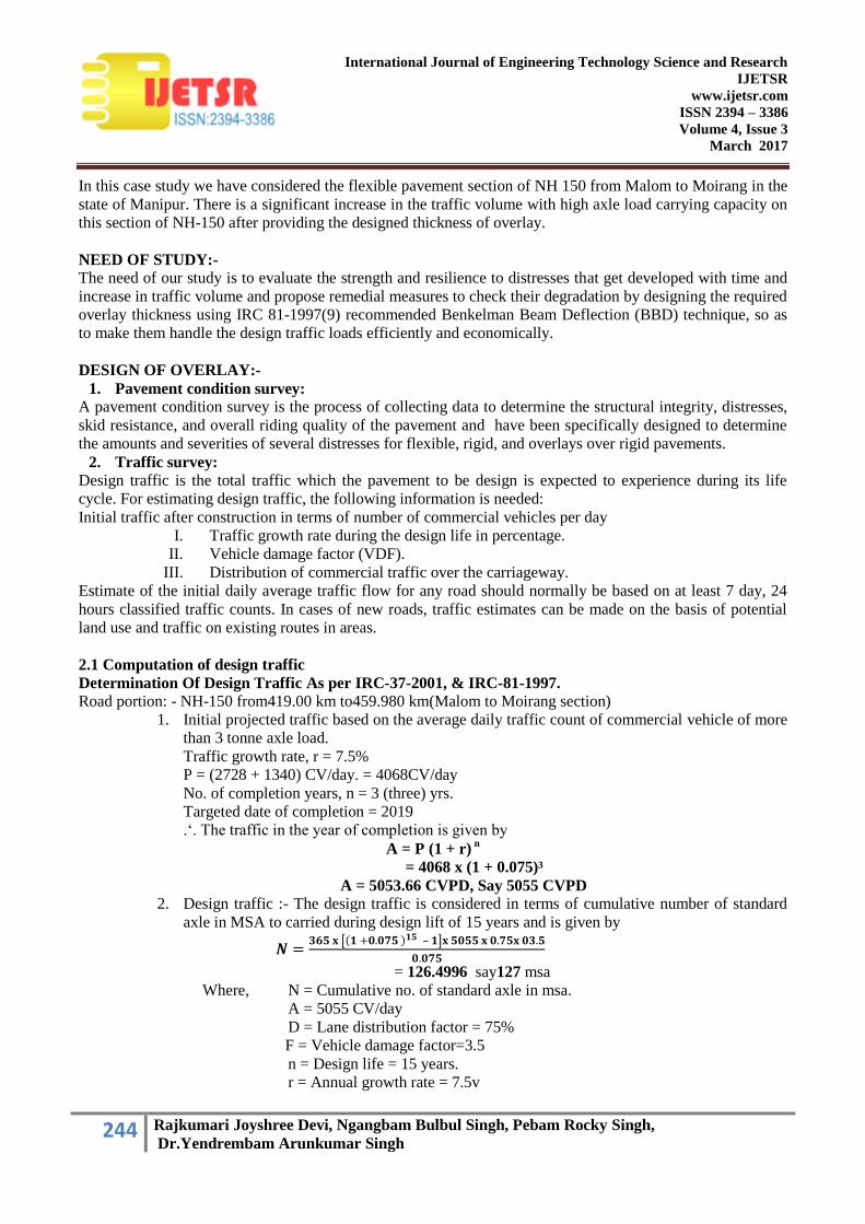
3. Evaluation of soil subgrade:- In the present study, we have evaluated the structural performance of a section of National Highway 150
from Malom to Moirang .We have conducted soil investigation survey including CBR test and other soil
properties as per IS-2720(14) .Soaked CBR test for sub-grade soil (4 days) as prescribed by IRC,SP-
72,2007 was carried out on the soil sample collected from the sites as shown in figure 1 . The samples
were collected from different locations as prescribed in IRC-37, 2001 and thetest results were presented in
the table2
FIGURE 1: COLLECTION OF SOIL SAMPLE
TABLE 2 :FIELD INFORMATION COLLECTED DURING PAVEMENT CONDITION SURVEYAs per
IRC 81-(1997)(9)
S
I
.
NO
.
LOCATION
SOIL CLASSIFICATION PROJCTER
DENSITY &
OMC
CBR AT OMC (4
DAYS SOAKED)
REM
ARK
S
LL% PL% PI% SOIL TYPE gm/cc % CB
R%
SAOKED
MOISTUR
E(%)
1 Km. 454.70O to
459.000
TH
E S
OIL
SA
MP
LE
S A
RE
CO
LL
EC
TE
D 1
ME
TR
E
BE
LO
W T
HE
GR
OU
ND
SU
RF
AC
E
FR
OM
TH
E
DIF
FE
RE
NT
LO
CA
TIO
N A
S P
ER
IR
C-3
7,
20
01
.
MALOM (456.500) 35.294 26.74 8.554 SILTY CLAY (SC) 1.87 14.5 7.05 20.20
2 Km. 448.000 to
454.700
Nambol (447.600) 45.45 29.73 15.72 SILTY CLAY (SC) 1.86 15.5 5.69 19.01
3 Km.442.000 to
447.950
Leimaram (443.000) 34.25 27.53 6.72 SILTY CLAY (SC) 1.76 14.15 6.55 20.42
4 Km. 436.000 to
441.950
Keinou (439.200) 34.56 26.44 8.12 SILTY CLAY (SC) 1.80 15.4 5.98 20.18
5 Km. 430.000 to
435.950
Bishnupur (433.000) 36.78 28.32 8.46 SILTY CLAY (SC) 1.79 15.8 5.72 19.38
6 Km. 424.000 to
434.950
Loktak Project Bridge
(428.100)
35.69 28.54 7.15 SILTY CLAY (SC) 1.82 15.62 5.95 20.05
Km. 419.000 to
423.950
Moirang (420) 37.89 28.43 9.46 SILTY CLAY (SC) 1.80 15.92 5.62 19.20
NAMBOL (447.600 KM) MALOM (456.500 KM)
247 Rajkumari Joyshree Devi, Ngangbam Bulbul Singh, Pebam Rocky Singh,
Dr.Yendrembam Arunkumar Singh
International Journal of Engineering Technology Science and Research
IJETSR
www.ijetsr.com
ISSN 2394 – 3386
Volume 4, Issue 3
March 2017
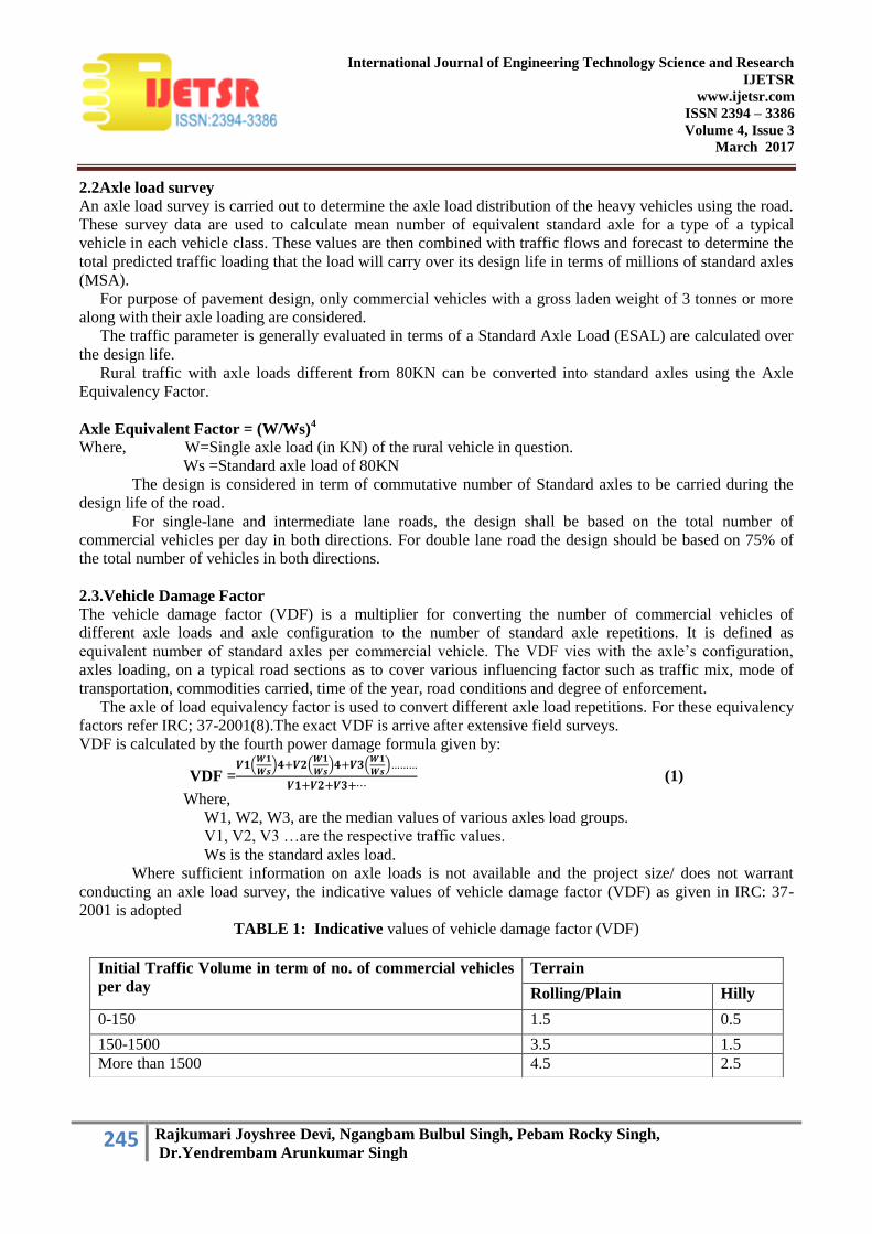
4. Pavement Deflection Measurement Using BBD Method:-
By performing the pavement defection measurement using BBD technique as per the recommendations of
IRC 81-1997(9), the characteristic deflection of the section (419.000 km – 459.000km) was found to be 1.62
mm. Using this values, the required design overlay thickness for strengthening the section came out to be 58
mm.
FIGURE 2 : MEASURING OF DEFLECTION TEST AT MALOM SECTION (454.700 – 459.000)KM
5. Analysis of data for overlay design
5.1 Characteristics deflection
Overlay design for a given section is based not on individual deflection values but on a statistical analysis of
all the measurements in the section corrected for temperature variations. This involves calculation of mean
deflection, standard deviation, and characteristic deflection. The characteristic deflection for design purposes
shall be taken as given in equations (4) and (5). The formulae to be used in the calculation are as follows :
Mean Deflection, x=∑𝑥
𝑛 --- (2)
Standard Deviation, 𝜎 = Σ(x −x )2
𝑛−1 --- (3)
Characteristic Deflection,
(i) Dc = x +2𝜎 ----(4)
for major arterial roads (like NH & SH)
(ii) Dc = 𝑥 + 𝜎 ---(5)
for all other roads
Where,
X = Individual deflection, mm
𝑋 = Mean deflection, mm
n = Number of deflection measurements
𝜎 = Standard deviation, mm
Dc = Characteristic deflection, mm
ℎ = R log10
𝐴𝑐
𝐴
Where,
h = thickness of the granular overlay (WBM)
R = constant which may be taken as 550
Ac = Characteristic deflection
A = Allowable deflection
5.2 Design of overlay
The deflection response obtain throughthe Benkaleman Beam is the function of the thickness of the pavement
layers, subgrade strength and environmental condition and the loading condition. The required overlay

248 Rajkumari Joyshree Devi, Ngangbam Bulbul Singh, Pebam Rocky Singh,
Dr.Yendrembam Arunkumar Singh
International Journal of Engineering Technology Science and Research
IJETSR
www.ijetsr.com
ISSN 2394 – 3386
Volume 4, Issue 3
March 2017
thickness is normaly calculated from the maximum deflection under the standard wheel load . A pavement
condition survey is an important part of the deflection based overlay design procedure, it establishes the need
for maintenance and rehabilitation.The Overlay thicknesss may be determined after deciding the allowable
deflection in the pavement under the design load. According to Ruiz‟s equation, overlay thickness h in cm is
given by
ℎ =𝑅
0.434log10
𝐴𝑐
𝐴 cm
Where, h = thickness of the granular overlay (WBM)
R = constant which may be taken as 550
Ac = Characteristic deflection
A = Allowable deflection The detail layer thickness of existing pavement found out during pavement condition survey shows in Figure 3.
The proposed design drawing and the thickness for different layers of the overlay section for the present study
section of NH-150 shown in Figure 4.
RESULTS AND CONCLUSIONS: From the present field study of the structural behaviour of National Highway-150 (Malom to Moirang)
usingBenkelman Beam Deflection method, the following results were obtained:
The actual pavement deflection obtained by the Benkelman beam method is more than 5mm
which shows the pavement requires strengthening for the existing traffic condition.
The exiting traffic as per the traffic count for 24 hours for 7 days shows that that the no. of
commercial vehicles whose axle load is more than 3 tons is as high as 5055 CVPD which is
much higher for the existing pavement thickness.
FIGURE 3
FIGURE 4

249 Rajkumari Joyshree Devi, Ngangbam Bulbul Singh, Pebam Rocky Singh,
Dr.Yendrembam Arunkumar Singh
International Journal of Engineering Technology Science and Research
IJETSR
www.ijetsr.com
ISSN 2394 – 3386
Volume 4, Issue 3
March 2017
From the field pavement deflection study the overlay required for strengthening the existing
pavement is 5.8cm which can be provided consisting of 2.1cm thick Dense Bituminous
Macadam(DBM) and three layers of 1.5cm thick (each) WBM course.
The subgrade soil was found to be silty clay and the subgrade soil bearing capacity was found
to be 6% which is more than the minimum specified CBR value for national highway.
From the present study it has been concluded that the National Highway-150 (malom to moirang section) in
the state of Manipur can carry the presenthigh volume of traffic with heavy axle load for another span of 10
years with regular routine maintenance as required from time to time.
REFERENCE
1. AASHTO (1972). "Interim Guide for Design of Pavement Structures" Washington D.C.
2. Das, A., and Pandey, B.B, “Analytical Design of Flexible pavement for planned Stage Construction,
“Indian Highways, Indian road Congress New Delhi, Vo. 27, no. 4, 1999,pp. II-35-II-42.
3. Das, A., Reddy, K.S, and Pandey, B.B, “Analytic Overlay Design and Validation:
4. Gopal Ranjan, "Basics and applied Soil Mechanics by Gopal Ranjan".
5. IRC (1971), “Proceedings, Seminar on strengthening of existing road pavement”, Indian Road Congress,
New Delhi.
6. IRC: 37(2001). “Guidelines For The Design Of Flexible Pavements” Indian Road Congress, New Delhi.
7. IRC: 81(1997). “Guidelines For Strengthening Of Flexible Road Pavements Using Benkelman Beam
Deflection Technique” Indian Road Congress, New Delhi.
8. IRC: SP: 72-2007; “Guidelines For The Design Of Flexible Pavements For Low Volume Rural Roads"
Indian Road Congress, New Delhi.
9. IS 2720 (1975). Methods of Test for Soil, Determination dry density of soils in place by core cutter
method, Part-XXIX, Bureau of Indian Standards, New Delhi.
10. IS 2720 (1980). Methods of Test for Soil, Determination of Specific Gravity, Part-III, Sec-2, Bureau of
Indian Standards, New Delhi.
11. IS 2720 (1985a). Methods of Test for Soil, Grain Size Analysis, Part-4, Bureau of Indian Standards, New
Delhi.
12. IS 2720 (1985b). Methods of Test for Soil, Determination of Liquid Limit and Plastic Limit, Part-5,
Bureau of Indian Standards, New Delhi.
13. IS 2720 (1987). Methods of Test for Soil, Laboratory determination of CBR, Part-16, Bureau of Indian
Standards, New Delhi.
14. Mahabir Prasad, Sharma, V.P.s and Jain B.K (1970), “ A study of Benkelman Beam Deflection for
assessment of flexible pavement performance in U.P.” Journal, Indian Road Congress Vol. XXXIII-2.
L =
LEFT
LA
NE