strength of materials - ibrahimshaikh.com of materials laboratory manual by prof. shaikh ibrahim...
TRANSCRIPT
STRENGTH OF MATERIALSlaboratory manual
By Prof. Shaikh Ibrahim Ismail
M.H. Saboo Siddik College of Engineering,MUMBAI
TABLE OF CONTENT
Sr. No. page no.
1. 3
2. 6
3. 11
4. 16
5. 19
6. 22
7. 26
8. 29
9. 32
10. 35
11.
Title of Experiment
Study of Universal Testing Machine(UTM)
Tensile Test on M.S. Specimen on UTM
Tensile Test on deformed bar on UTM
Impact Test (IZOD) on Metals
Impact Test (Charpy) on Metals
Flexural Test on Timber (Single Point)
Flexural Test on Timber (Double Point)
Hardness Test on Metals (Brinell)
Hardness Test on Metals (Rockwell)
Shear Test on Metals (Single and Double)
Torsion Test on Mild Steel 38

EXPERIMENT NO: _____ DATE: ____________
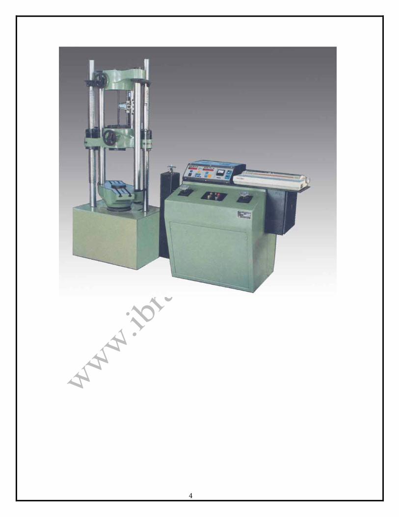
STUDY OF UNIVERSAL TESTING MACHINE
PURPOSE: Various materials are used in the construction and manufacturing
fields. These materials are subjected to various forces and stresses. Practically all required tests can be performed on the UTM. Hence the study of this device is very important
OBJECTIVES: 1. To identify different parts.2. To understand working of the machine.3. To develop skill in handling fixtures and attachments for various
tests.
APPARATUS: UTM, fixtures and attachments.
INSTRUCTIONS: 1. Observe the UTM in laboratory.2. The teacher explains various parts and their functions. Different parts
of machine are numbered and their purpose and functions infollowing table.
3. You will be shown fixtures and attachments of the UTM.4. Observe the demonstrations of fixing and attachments to carry out
various tests. In a group try to fix them under the guidance of teacher.5. Write in ten lines the working principle of UTM.
3
4

OBSERVATIONS:
NAME OF PARTS PURPOSE/ FUNCTION Upper Head It is the topmost part of the UTM and is used to
grip the upper end of the specimen. It is fixed and has 2 cross screws and a shaft attached at cross slide to provide proper tensile stress or compressive stress.
Hand Wheel It is used to open and close the mouth of the upper head and middle head too grip or adjust the specimen
Cross Head The middle head of the UTM is one of its most important parts. It has upward and downward movements. Because of these movements stresses and strains are developed. It has two screws and shaft passing through its two ends, each pair connected.
Shaft Shaft is one of the most important and useful parts of the UTM. It supports the whole UTM and also delivers power to the machine. It is smooth and fixed.
Lower Head It is called the lower head because it is at the lowest part of the machine. It provides support for the base of the machine. On the lower head various tests can also be performed. It is fixed and has 2 shafts and screws connected same as in upper and middle head.
Measuring Scale It shows reading of the cross head. Right handed screw shaft
It is used as a path to raise or lower the cross head.
Bellow Used for protection. Digital Display It displays deflection and load digitally. It can be
controlled with numerous control buttons. Control Buttons ON / OFF buttons are used to start and shut down
the machine.
CONCLUSION:
5
EXPERIMENT NO: _____ DATE: ____________
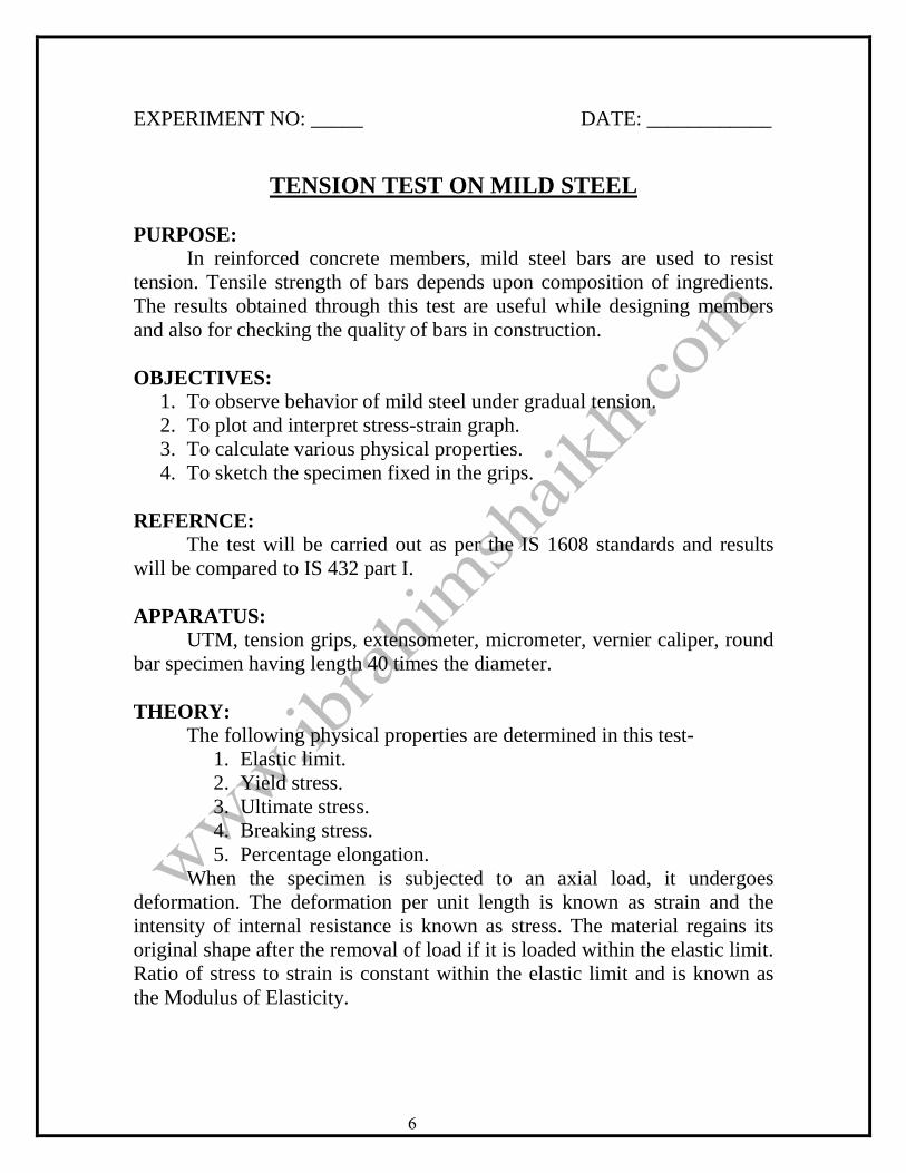
TENSION TEST ON MILD STEEL
PURPOSE: In reinforced concrete members, mild steel bars are used to resist
tension. Tensile strength of bars depends upon composition of ingredients. The results obtained through this test are useful while designing members and also for checking the quality of bars in construction.
OBJECTIVES: 1. To observe behavior of mild steel under gradual tension.2. To plot and interpret stress-strain graph.3. To calculate various physical properties.4. To sketch the specimen fixed in the grips.
REFERNCE: The test will be carried out as per the IS 1608 standards and results
will be compared to IS 432 part I.
APPARATUS: UTM, tension grips, extensometer, micrometer, vernier caliper, round
bar specimen having length 40 times the diameter.
THEORY: The following physical properties are determined in this test-
1. Elastic limit.2. Yield stress.3. Ultimate stress.4. Breaking stress.5. Percentage elongation.
When the specimen is subjected to an axial load, it undergoes deformation. The deformation per unit length is known as strain and the intensity of internal resistance is known as stress. The material regains its original shape after the removal of load if it is loaded within the elastic limit. Ratio of stress to strain is constant within the elastic limit and is known as the Modulus of Elasticity.
6

SPECIMEN
7

Stress = Load / Cross sectional area Strain = Change in length / original length Modulus of Elasticity [E] = stress / strain
Percentage elongation of the material gives certain measure of ductility and is measured in standard gauge length and is taken Vsa where, ‘sa’ is the sectional area.
INSTRUCTIONS: 1. Sketch the wedge grips used to fix the specimen.2. Mark the specimen by punch at interval of 10 mm along the length.
Distance between grips should be 20 times the diameter.3. Observe the adjusted loading range and note the same.4. Fix specimen between grips.5. Adjust gauge length on extensometer and fix it on middle portion of
the bar. Adjust the zero of extensometer and the measuring device ofUTM.
6. Switch on the machine, take extensometer readings for the specifiedintervals and record them.
7. Observe the hesitation [vibration] in movement of load dial andindicator will move somewhat to and fro. Record upper load andlower load at this moment. That gives the upper and lower yield point.
8. Record further extensions on extensometer. The stage from plasticrange to ultimate load is known as strain hardening stage.
9. Observe neck formation at ultimate load & main indicator comingback.
10. Record breaking load. Noise is heard of the specimen. Switch of themachine.
11. Remove specimen. It will be hot at the point of fracture.12. Adjust the cup and cone to rejoin the specimen and find out the final
gauge length. Measure final diameter at fracture. 13. If fracture is near the grip, test has to be repeated.
OBSERVATIONS: 1. Least count of Extensometer:______________2. Actual diameter:________________________3. Gauge length – initial :___________________
Final: ___________________ 4. Distance between grips:__________________
8

Observation Table:
Sr. No.
Load (P)
Def. (δ)
Stress (σ)
Strain (e)
Mod. (E)
Sr. No.
Load (P)
Def. (δ)
Stress (σ)
Strain (e)
Mod. (E)
9
CALCULATIONS: 1. Stress
2. Strain
3. Percentage elongation
4. Breaking stress
5. Modulus of Elasticity
GRAPHS: STRESS vs STRAIN graph upto failure load.
Mark the following Points on the graphs: 1. Yield stress.2. Ultimate stress.3. Breaking stress.4. Elastic range.5. Plastic range.6. Strain hardening range.
CONCLUSION:
10

EXPERIMENT NO:_____ DATE:____________
TENSION TEST ON DEFORMED BAR
PURPOSE: Deformed bars are twisted bars. They increase the bond between
concrete and steel. Now-a-days deformed bars are commonly used in construction. There are different varieties of deformed bars. Tension steel test helps in designing structural members. It also provides a check on quality of deformed bars used.
OBJECTIVES: 1. To observe behavior of bar under gradual and uniaxial tension.2. To plot and interpret stress-strain graphs.3. To calculate physical properties of specimen.
APPARATUS: UTM, weighing balance extensometer, specimen of deformed bar.
REFERENCE: Test will be carried out as per IS-1608 and results will be compared
with IS-1139.
THEORY: The deformed bar is not having perfect yield point as that of M.S.
therefore, 0.2% proof stress is taken as measure of elastic limit.
INSTRUCTIONS: 1. Sketch the wedge grips used to fix the specimen.2. Mark the specimen by punch at interval of 10 mm along the length.
Distance between grips should be 20 times the diameter.3. Observe the adjusted loading range and note the same.4. Fix specimen between grips.5. Adjust gauge length on extensometer and fix it on middle portion of
the bar. Adjust the zero of extensometer and the measuring device ofUTM.
6. Switch on the machine, take extensometer readings for the specifiedintervals and record them.
11

12

7. Observe the hesitation [vibration] in movement of load dial andindicator will move somewhat to and fro. Record upper load andlower load at this moment. That gives the upper and lower yield point.
8. Record further extensions on extensometer. The stage from plasticrange to ultimate load is known as strain hardening stage.
9. Observe neck formation at ultimate load & main indicator comingback.
10. Record breaking load. Noise is heard of the specimen. Switch of themachine.
11. Remove specimen. It will be hot at the point of fracture.12. Adjust the cup and cone to rejoin the specimen and find out the final
gauge length. Measure final diameter at fracture. 13. Draw sketch of the specimen showing cup and cone.14. If fracture is near the grip, test has to be repeated.
OBSERVATIONS: 1. Nominal Diameter:__________________2. Actual Diameter:____________________3. Gauge Length – Initial:_______________
Final:_______________ 4. Diameter of Specimen:_______________
13

Observation Table:
Sr. No.
Load (P)
Def. (δ)
Stress (σ)
Strain (e)
Mod. (E)
Sr. No.
Load (P)
Def. (δ)
Stress (σ)
Strain (e)
Mod. (E)
14

GRAPHS: Plot Stress vs Strain.
CALCULATIONS: 1. Select a point on graph and note stress and strain.2. modulus of elasticity:3. Mark 0.2% strain on the graph and draw a line parallel to the straight
line section of the graph.4. Note down 0.2% proof stress where straight line out stress-strain
curve.
CONCLUSION:
15

EXPERIMENT NO: _____ DATE: ____________
IZOD IMPACT TEST ON METALS
PURPOSE: Many structural parts or machine parts are subjected to impact loads.
Therefore, it is necessary to know resistance of materials to such impact load. The purpose of this test is to find resistance to impact or shock absorbing capacity of materials.
OBJECTIVES: 1. To understand principles of impact tests.2. To determine shock absorbing capacity of materials using IZOD
impact test.3. Compare impact resisting qualities of different materials.
REFERENCE: IS-1598-1960 / IS-1757-1973
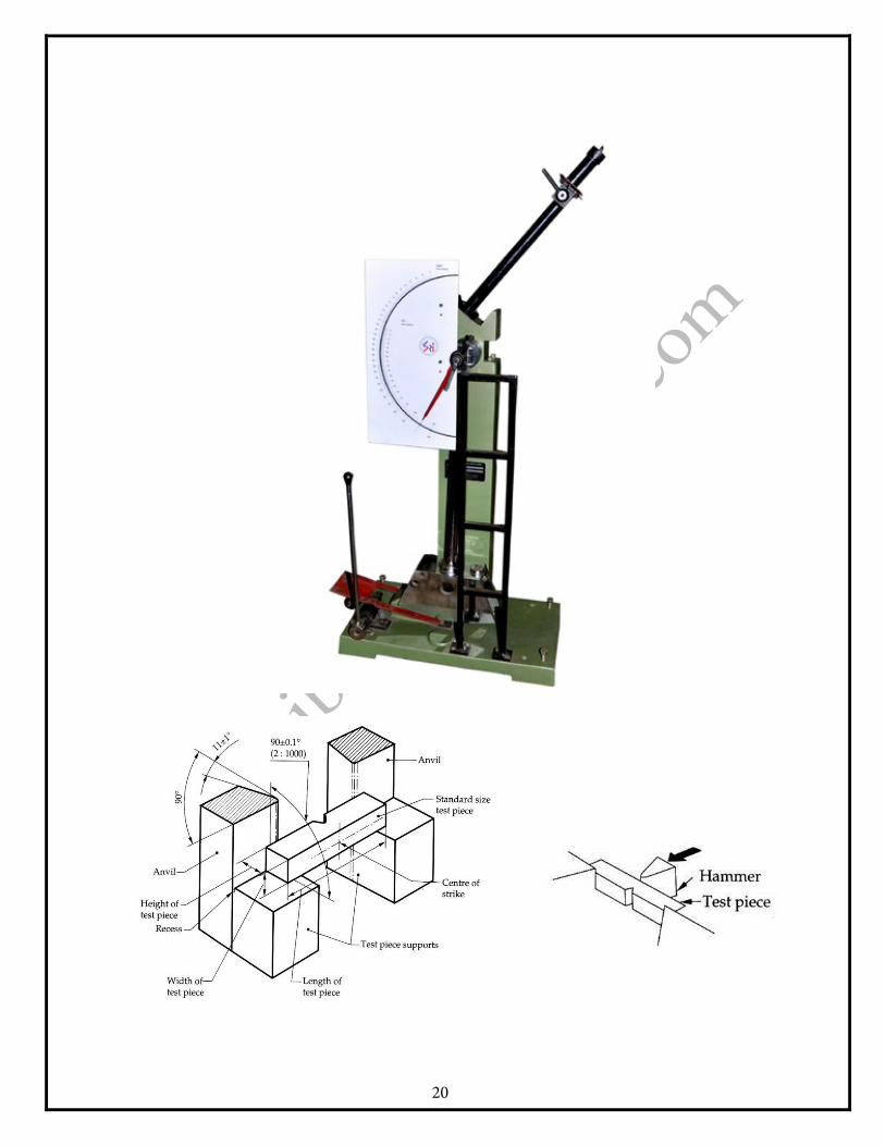
APPARATUS: Impact testing machine, standard specimen.
PROCEDURE: 1. Raise the pendulum hammer to the required height. Release it
allowing a free swing and observe the energy allowable available in the hammer.
2. Raise the pendulum again to the same height as before and clamp it.3. Fix the specimen in anvil properly.4. See that nobody is standing in the swinging range of the pendulum.
Release the hammer by operating the release mechanism. Thespecimen breaks and hammer swings to the other side.
5. Observe the energy reading on the scale after breaking the specimen.Note it as final energy reading.
6. Repeat procedure for different specimen materials.7. Calculate shock absorbing capacity and note it down.
16

17

OBSERVATIONS:
SR. NO.
MATERIAL INTERNAL ENERGY (joules)
EXTERNAL ENERGY
(joules)
SHOCK ABSORBER
REMARKS
1
2
3
CONCLUSION:
18

EXPERIMENT NO: _____ DATE: ____________
CHARPY IMPACT TEST ON METALS
PURPOSE: Many structural parts or machine parts are subjected to impact loads.
Therefore, it is necessary to know resistance of materials to such impact load. The purpose of this test is to find resistance to impact or shock absorbing capacity of materials.
OBJECTIVES: 1. To understand principles of impact tests.2. To determine shock absorbing capacity of materials using IZOD
impact test.3. Compare impact resisting qualities of different materials.
REFERENCE: IS-1598-1960 / IS-1988-1994
APPARATUS: Impact testing machine, standard specimen.
PROCEDURE: 1. Raise the pendulum hammer to the required height. Release it
allowing a free swing and observe the energy allowable available in the hammer.
2. Raise the pendulum again to the same height as before and clamp it.3. Fix the specimen in anvil properly.4. See that nobody is standing in the swinging range of the pendulum.
Release the hammer by operating the release mechanism. Thespecimen breaks and hammer swings to the other side.
5. Observe the energy reading on the scale after breaking the specimen.Note it as final energy reading.
6. Repeat procedure for different specimen materials.7. Calculate shock absorbing capacity and note it down.
19
20

OBSERVATIONS:
SR. NO.
MATERIAL INITIAL ENERGY
(joules)
FINAL ENERGY
(joules)
SHOCK ABSORBER
REMARKS
1
2
3
CONCLUSION:
21

EXPERIMENT NO: _____ DATE: ____________
FLEXURAL TEST FOR TIMBER
PURPOSE: Timber is one of the most widely used materials in traditional
structures. The properties of timber vary according to the directions of grains. Members are subjected to axial loads and bending action. It is necessary to understand the behavior of timber in bending. It helps in designing the members.
OBJECTIVES: 1. To understand the test procedure.2. To determine the important properties.
REFERENCE: IS 1708
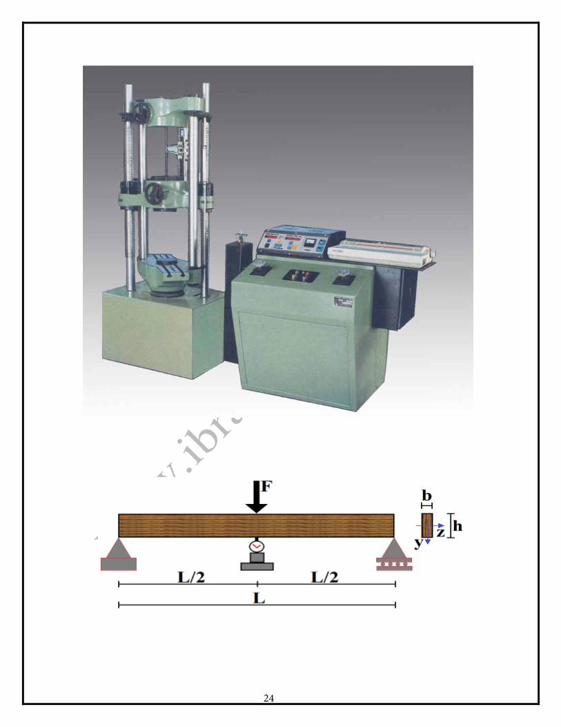
APPARATUS: UTM, bending attachment, scale, verner dial caliper gauge with
magnetic base, specimen of 50×50×75 mm with grains approximately parallel to its longitudinal edge.
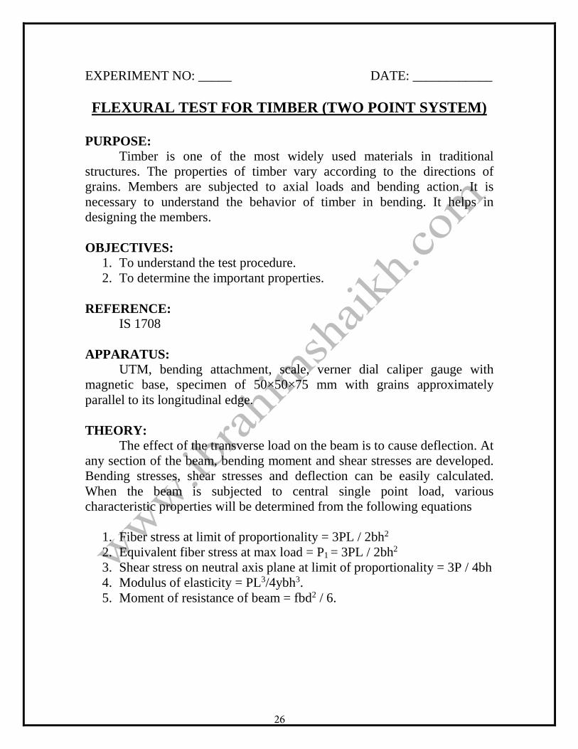
THEORY: The effect of the transverse load on the beam is to cause deflection. At
any section of the beam, bending moment and shear stresses are developed. Bending stresses, shear stresses and deflection can be easily calculated. When the beam is subjected to central single point load, various characteristic properties will be determined from the following equations
1. Fiber stress at limit of proportionality = 3PL / 2bh2
2. Equivalent fiber stress at max load = P1 = 3PL / 2bh2
3. Shear stress on neutral axis plane at limit of proportionality = 3P / 4bh4. Modulus of elasticity = PL3/4ybh3.5. Moment of resistance of beam = fbd2 / 6.6. Load at limit of proportionality = 17.5 kNWhere,
P = Load at limit of proportionality (it is taken as a point on load –deflection curve at which graph deviates from the straight line)
22

L = Span of test specimen. b = Breadth of test specimen h = Depth of test specimen y = Deflection at limit of proportionality.
INSTRUCTIONS: 1. Measure cross sectional dimensions of test specimen and note them.2. Adjust required span and place specimen on roller supports.3. Fix the dial gauge below specimen at centre of span.4. Apply the load at a constant rate and record deflections at interval of
500N.5. Record load at rupture.
23
24

OBSERVATIONS: 1. Span of beam = L = _________________2. Breadth of beam = b = _________________3. Depth of beam = h = _________________
CALCULATIONS: 1. Moment of beam = fbd / 6=
2. Modulus of elasticity, E = PL / 4ybh
3. Moment of max stress = M / Z
CONCLUSION:
25
EXPERIMENT NO: _____ DATE: ____________
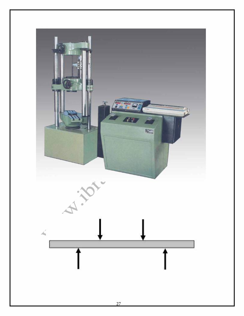
FLEXURAL TEST FOR TIMBER (TWO POINT SYSTEM)
PURPOSE: Timber is one of the most widely used materials in traditional
structures. The properties of timber vary according to the directions of grains. Members are subjected to axial loads and bending action. It is necessary to understand the behavior of timber in bending. It helps in designing the members.
OBJECTIVES: 1. To understand the test procedure.2. To determine the important properties.
REFERENCE: IS 1708
APPARATUS: UTM, bending attachment, scale, verner dial caliper gauge with
magnetic base, specimen of 50×50×75 mm with grains approximately parallel to its longitudinal edge.
THEORY: The effect of the transverse load on the beam is to cause deflection. At
any section of the beam, bending moment and shear stresses are developed. Bending stresses, shear stresses and deflection can be easily calculated. When the beam is subjected to central single point load, various characteristic properties will be determined from the following equations
1. Fiber stress at limit of proportionality = 3PL / 2bh2
2. Equivalent fiber stress at max load = P1 = 3PL / 2bh2
3. Shear stress on neutral axis plane at limit of proportionality = 3P / 4bh4. Modulus of elasticity = PL3/4ybh3.5. Moment of resistance of beam = fbd2 / 6.
26
27
INSTRUCTIONS: 1. Measure cross sectional dimensions of test specimen and note them.2. Adjust required span and place specimen on roller supports.3. Fix the dial gauge below specimen at centre of span.4. Apply the load at a constant rate and record deflections at interval of
500N.5. Record load at rupture.
OBSERVATIONS: 1. Span of beam = L = _________________2. Breadth of beam = b = _________________3. Depth of beam = h = _________________
GRAPH: Plot the graph of load versus deflection.
CALCULATIONS: 1. Load at limit of proportionality =
2. Fiber stress =
3. Moment of resistance =
4. Modulus of elasticity =
5. Horizontal shear stress =
CONCLUSION:
28
EXPERIMENT NO: _____ DATE: ____________
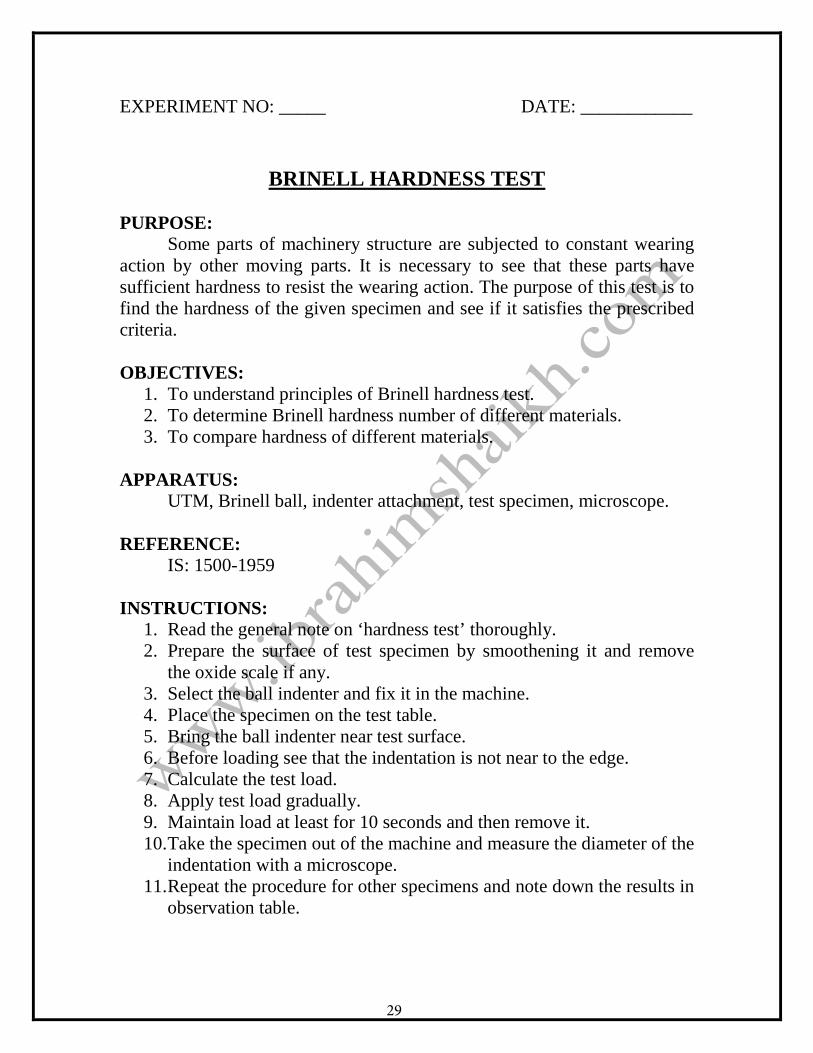
BRINELL HARDNESS TEST
PURPOSE: Some parts of machinery structure are subjected to constant wearing
action by other moving parts. It is necessary to see that these parts have sufficient hardness to resist the wearing action. The purpose of this test is to find the hardness of the given specimen and see if it satisfies the prescribed criteria.
OBJECTIVES: 1. To understand principles of Brinell hardness test.2. To determine Brinell hardness number of different materials.3. To compare hardness of different materials.
APPARATUS: UTM, Brinell ball, indenter attachment, test specimen, microscope.
REFERENCE: IS: 1500-1959
INSTRUCTIONS: 1. Read the general note on ‘hardness test’ thoroughly.2. Prepare the surface of test specimen by smoothening it and remove
the oxide scale if any.3. Select the ball indenter and fix it in the machine.4. Place the specimen on the test table.5. Bring the ball indenter near test surface.6. Before loading see that the indentation is not near to the edge.7. Calculate the test load.8. Apply test load gradually.9. Maintain load at least for 10 seconds and then remove it.10. Take the specimen out of the machine and measure the diameter of the
indentation with a microscope.11. Repeat the procedure for other specimens and note down the results in
observation table.
29
30

OBSERVATION TABLE: Sr. No. Metal P / D2 Ball dia
(D) Load (P) kg
Time (t) sec
Indenter dia.
BHN
CALCULATIONS:
BHN = 2P / π D [ D – ( D2 – d2 )0.25
RESULT:
31
EXPERIMENT NO: _____ DATE: ____________
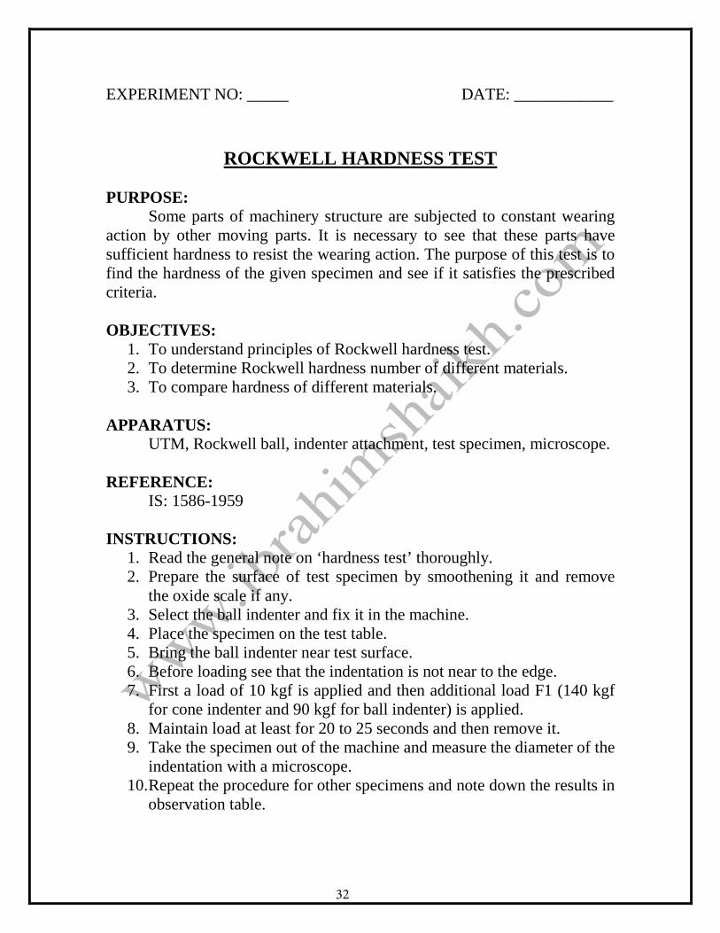
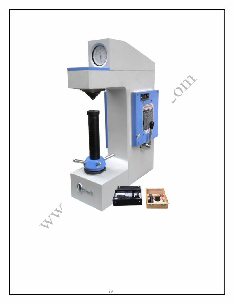
ROCKWELL HARDNESS TEST
PURPOSE: Some parts of machinery structure are subjected to constant wearing
action by other moving parts. It is necessary to see that these parts have sufficient hardness to resist the wearing action. The purpose of this test is to find the hardness of the given specimen and see if it satisfies the prescribed criteria.
OBJECTIVES: 1. To understand principles of Rockwell hardness test.2. To determine Rockwell hardness number of different materials.3. To compare hardness of different materials.
APPARATUS: UTM, Rockwell ball, indenter attachment, test specimen, microscope.
REFERENCE: IS: 1586-1959
INSTRUCTIONS: 1. Read the general note on ‘hardness test’ thoroughly.2. Prepare the surface of test specimen by smoothening it and remove
the oxide scale if any.3. Select the ball indenter and fix it in the machine.4. Place the specimen on the test table.5. Bring the ball indenter near test surface.6. Before loading see that the indentation is not near to the edge.7. First a load of 10 kgf is applied and then additional load F1 (140 kgf
for cone indenter and 90 kgf for ball indenter) is applied.8. Maintain load at least for 20 to 25 seconds and then remove it.9. Take the specimen out of the machine and measure the diameter of the
indentation with a microscope.10. Repeat the procedure for other specimens and note down the results in
observation table.
32
33

OBSERVATION TABLE: Sr. No. Metal P / D2 Ball dia
(D) Load (P) kg
Time (t) sec
Indentor dia
HRN
CALCULATIONS:
HRN =
RESULT:
34
EXPERIMENT NO: _____ DATE: ____________
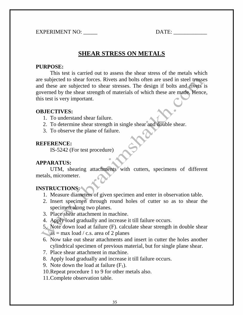
SHEAR STRESS ON METALS
PURPOSE: This test is carried out to assess the shear stress of the metals which
are subjected to shear forces. Rivets and bolts often are used in steel trusses and these are subjected to shear stresses. The design if bolts and rivets is governed by the shear strength of materials of which these are made. Hence, this test is very important.
OBJECTIVES: 1. To understand shear failure.2. To determine shear strength in single shear and double shear.3. To observe the plane of failure.
REFERENCE: IS-5242 (For test procedure)
APPARATUS: UTM, shearing attachments with cutters, specimens of different
metals, micrometer.
INSTRUCTIONS: 1. Measure diameters of given specimen and enter in observation table.2. Insert specimen through round holes of cutter so as to shear the
specimen along two planes.3. Place shear attachment in machine.4. Apply load gradually and increase it till failure occurs.5. Note down load at failure (F). calculate shear strength in double shear
as = max load / c.s. area of 2 planes6. Now take out shear attachments and insert in cutter the holes another
cylindrical specimen of previous material, but for single plane shear.7. Place shear attachment in machine.8. Apply load gradually and increase it till failure occurs.9. Note down the load at failure (F1).10. Repeat procedure 1 to 9 for other metals also.11. Complete observation table.
35
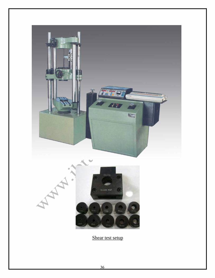
Shear test setup
36

OBSERVATION TABLE: SR NO.
Specimen Metal
Dia Area Single Shear Double shear LOAD STRESS LOAD STRESS
1.
2.
3.
CALCULATIONS: Shear stress = load / area
RESULT:
37
EXPERIMENT NO: _____ DATE: ____________
TORSION TEST ON MILD STEEL
PURPOSE: Some parts of machines are subjected to angular motion. The angular
motion develops twisting moment in the member. Failure of member occurs in different ways. Shear strength of material and modulus of rigidity govern the behavior of material in torsion. This test would enable you to understand the behavior of mild steel and iron under torsion.
THEORY: Consider a solid cylindrical shaft fixed at one end and subjected to
twisting at the free end as shown. The effect of twisting, changes the position of fibre AB to AB’. Angle of twist of free end is BOB’ = e.
Where, T = Torque of twisting moment Ip = Polar moment of inertia Rs = Ultimate shear stress R = Radius of shaft G = Modulus of rigidity θ = angle of twist in radians. L = length of shaft
APPARATUS: UTM with twisting fitment, specimen.
PROCEDURE: The length and diameter of the specimen are measured and noted. The specimen is held in grips of torsion twisting machine. One end of specimen is twisted either normally or mechanically. Twisting moments at various instants and corresponding values of
angle of twist (Ө) are recorded and modulus of rigidity of the specimen is found G = T L / Ip θ
38
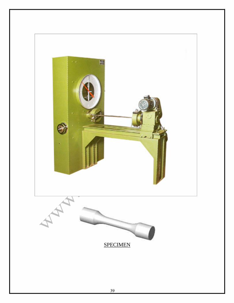
SPECIMEN
39
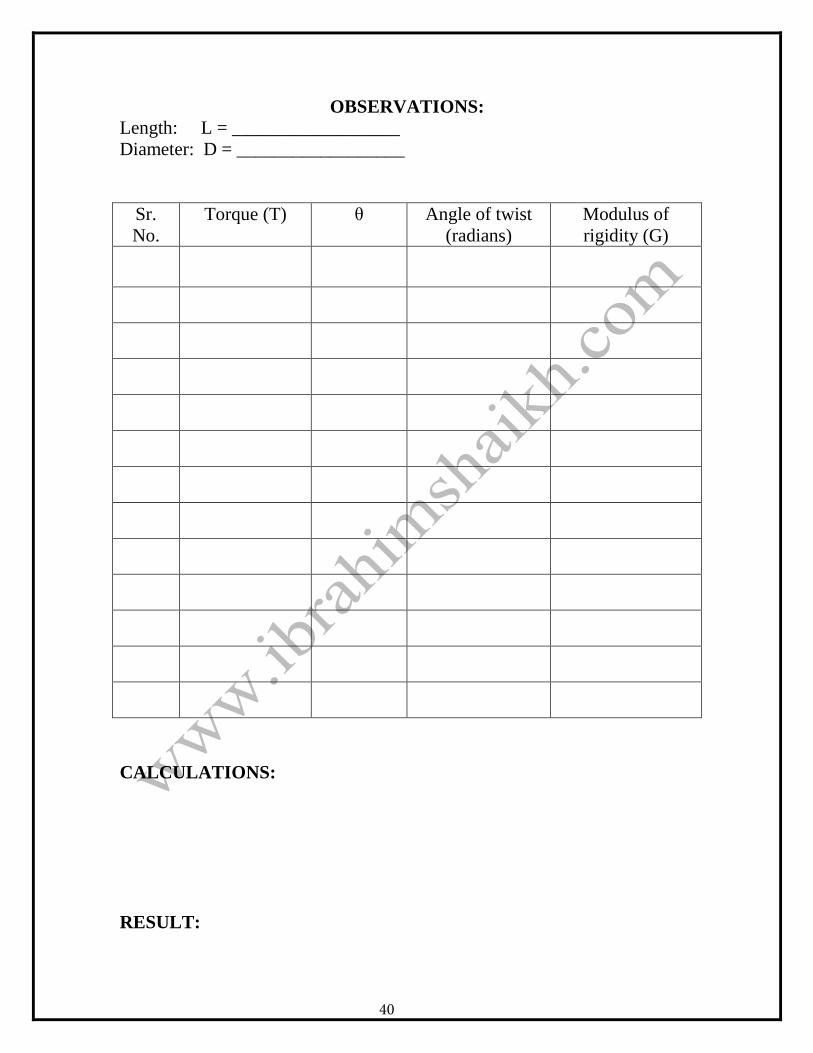
OBSERVATIONS: Length: L = __________________ Diameter: D = __________________
Sr. No.
Torque (T) θ Angle of twist (radians)
Modulus of rigidity (G)
CALCULATIONS:
RESULT:
40