strength, constructi on and watertight … · which should comply with the relevant parts of bs...
TRANSCRIPT
MSIS004/PT II/REV 1.01/PAGE 1 OF 30
PART II
STRENGTH, CONSTRUCTION AND WATERTIGHT SUBDIVISION
2.1 Submission of Plans and Particulars 2.1.1 General
2.1.1.1 To determine whether the proposals relating to the construction of the ship comply with the requirements of the Regulations the surveyor should obtain from the shipbuilder, owner, or his consultant, all plans and particulars necessary for the consideration of the case and submit them to Headquarters, together with any observations he may make from his own examination of the plans. 2.1.1.2 All plans, particulars and calculations should be in the English language, or should include an adequate English translation. Measurements should be in metric units.
2.1.2 Importance of early submission of plans
2.1.2.1 The shipbuilder or his consultant should be informed by the surveyor of the importance of the early submission of the drawings and particulars listed in paragraph 2.2.1. Work on the construction of the ship should await the acceptance of the submitted plans and particulars as inconvenience and delay may arise if alterations to the proposals are considered necessary. 2.1.2.2 The receipt of all plans and documents is to be acknowledged immediately. Surveyors should make every endeavour to ensure the expeditious return of submitted plans and documents and/or comments appropriate to them. 2.1.2.3 As the construction of the ship proceeds, the surveyor should ensure that the arrangements and details are in accordance with the accepted plans and particulars.
2.2 Strength of the Hull (Regulation 6) 2.2.1 Plans and particulars to be submitted The plans and particulars to be submitted should include those specified below, as appropriate to the Class of the ship being considered, and such other information as may be necessary for the full consideration of the proposals being offered for
MSIS004/PT II/REV 1.01/PAGE 2
compliance with the MCA’s requirements for the issue of a Passenger and Safety Certificate, a Passenger Certificate or a Certificate of Survey.

MSIS004/PT II/REV 1.01/PAGE 3
2.2.2 Hull structural plans:-
2.2.2.1 (a) Midship section showing longitudinal and transverse material (b) Profile and decks (c) Shell expansion including bilge keel construction and attachment to the
hull (d) Watertight and oil-tight bulkheads (e) After end construction (f) Fore end construction (g) Engine room construction and engine and thrust seatings (h) Pillars and girders (i) Double bottom structure (j) Sternframe (k) Rudder, stock and tiller (l) Propeller shaft brackets (m) Ship side doors (n) Stabilising fins and lateral thrust units where fitted. 2.2.2.2 All plans should identify the nature and physical properties of the materials being used and their means of connection, particularly where it is intended to use steels of special quality and aluminium alloy. 2.2.2.3 Where the ship is to be classed with a recognised Classification Society, namely Lloyds Register of Shipping, the American Bureau of Shipping, Bureau Veritas, Det Norske Veritas, Germanischer Lloyd or Registro Italiano Navale it will be sufficient for the surveyor to obtain from the shipbuilder or consultant stamped approved copies of the drawings submitted to the Classification Society together with that Society's approval. 2.2.2.4 The surveyor should ensure that the scantlings are approved for the designed subdivision draught and the strength is sufficient for the service intended. 2.2.2.5 Plans showing the scantlings and details of construction of all watertight bulkheads and all tanks forming part of the internal structure, e.g. oil fuel storage and settling tanks, water ballast and fresh water tanks are to indicate the maximum head of water which they might have to sustain in accordance with Schedule 4 in Merchant Shipping Notice MSN 1699(M) such that the maximum head sustained would include any additional water estimated under Regulation 33, paragraph 4(b) of Part V of the Regulations which may result from flooding or heeling.
2.2.3 Survey of hull before painting etc. The survey of a ship during construction is for the purpose of enabling the surveyor to form an opinion of the construction and workmanship and the surveyor should

MSIS004/PT II/REV 1.01/PAGE 4
not undertake the survey of a new ship after the hull is painted, cemented or otherwise coated. Where such coatings have been applied prior to survey the surveyor should take whatever action he deems necessary in order to satisfy himself that the construction and workmanship are satisfactory for the service intended and in accordance with the submitted plans. 2.2.4 Dry docking If the outside of the hull and fittings of a new passenger ship have been surveyed and accepted by the surveyor before the ship is launched, they need not be again examined in dry dock after launching unless the surveyor has reason to do so. In either case a suitable record should be made in the Dry Docking Book. 2.3 Quality and Tests of Materials 2.3.1 General The surveyor should be satisfied with the quality, strength and testing of the materials used in the construction of the hull, bulkheads, decks, superstructures and deckhouses; and the materials used in the attachments thereto, is to be in accordance with the requirements of a recognised Classification Society. 2.3.2 Glass-reinforced plastics
2.3.2.1 When it is intended to use glass-reinforced plastics in the construction of a ship, details of the extent to which the material is to be used should be submitted well in advance of the date it is proposed to commence work. Depending on the extent to which the material is to be used, further details may be required of the resins, fillers, and glass fibre reinforcements which should comply with the relevant parts of BS 3532 of 1990, 3496 of 1989 (1995), 3691 of 1990 (1995) and 3396 and 3749 of 1991, and are to be acceptable to the MCA. 2.3.2.2 The MCA will require to be satisfied that the premises are suitable, and that persons who are employed have been properly trained for the type of work to be undertaken. 2.3.2.3 Whenever glass-reinforced plastic is used in the construction of the hull, decks, superstructure, deckhouses or bulkheads, the laminates should be self extinguishing from fire considerations. The self extinguishing property should be imparted to the whole of the laminate. The test method to be used for ensuring that this requirement is complied with is described in Appendix E to these Instructions. 2.3.2.4 Should it be proposed to construct the hull, decks, superstructure, deckhouses or bulkheads with special laminates to afford the same degree of protection against fire as that obtained by the use of self extinguishing laminates, full details should be submitted for consideration.

MSIS004/PT II/REV 1.01/PAGE 5
2.3.3 Materials for side scuttles and windows
2.3.3.1 Type approved design The materials acceptable to the MCA for use in construction of “type approved” side scuttles and windows are given in BSMA 24 and 25 or their ISO equivalents, namely ISO 1751 and 3903. To ensure that the materials are of the correct quality, the surveyor should request the side scuttle manufacturer to provide copies of supporting documentation i.e., type approval and test certificates which may be compared with the requirements of the applicable standard. 2.3.3.2 Class approved design Side scuttles and windows constructed in accordance with the requirements of a recognised Classification Society are to have supporting documentation in the form of approved drawings, stamped and endorsed by the society. 2.3.3.3 Non-approved type Side scuttles and windows of a non-approved type are to be approved by the surveyor on an individual basis for the vessel concerned. The constructional drawings, properties and thickness of glass and chemical composition and mechanical strength of materials used in the construction of the frames should be in accordance with the requirements of an applicable standard. The thickness of glass pane is to be appropriate to the size and position on the vessel and in accordance with BSMA 24 or 25 or the equivalent ISO standard 5780 and 1751 or 5779 and 3903. Where non-approved windows and frames do not conform with a recognised standard, full details including supporting documentation are to be submitted to the certifying authority for consideration of acceptance as an “equivalent” to the requirements of a relevant standard. 2.3.3.4 Glazing materials other than glass The materials used for side scuttles, windows, promenades and deck spaces should normally be heat treated toughened glass. However, the use of other materials may be considered provided these fulfil relevant provisions for strength, structural fire protection, visibility and location and suitability for use in escapes. In general where it is proposed to use materials other than toughened safety glass, their use should be in accordance with the requirements of an acceptable standard appropriate to the proposed class and service of the vessel. Otherwise, full details of the proposed materials and their proposed use should be submitted to the MCA for approval.
MSIS004/PT II/REV 1.01/PAGE 6
2.3.3.5 Internal Glazing and other Translucent Divisions Materials other than heat treated toughened glass will be accepted for internal glazed divisions provided they are shown to “break safely”, comply with the requirements of an accepted standard and are appropriate for the class and service of the vessel. An appropriate standard for consideration would be BS 6206:1981 which relates to the impact testing of glazed constructions used in land based applications, copies of test certificates should be available from the manufacturers on request. Alternatively, appropriate marked toughened glass panes, in accordance with BSMA 25 or ISO 614 may be accepted for internal screen divisions with the recommendation that panes which exceed 0.75 sq m in area have a minimum thickness of 10mm and those smaller in area have a minimum thickness of 6mm. In cases where the surveyor is unsure as to the acceptability of the proposal, full details should be submitted to the MCA for their consideration
2.4 Construction of Watertight Bulkheads (Regulation 7) 2.4.1 General
2.4.1.1 Every watertight subdivision bulkhead or other portion of the internal structure forming part of the watertight subdivision of the ship is to be constructed in accordance with Schedule 4 of Merchant Shipping Notice MSN 1699(M). 2.4.1.2 Bulkhead stiffeners should not be spaced more than 610mm apart on a collision bulkhead or more than 915mm apart on any other watertight bulkhead unless other structural arrangements can be shown to be equally effective.
2.4.2 Initial tests of bulkheads, etc.
2.4.2.1 All watertight bulkheads, decks, etc. should be examined by the surveyor. 2.4.2.2 Main compartments may be tested by filling with water, but this is NOT compulsory. Where this is not carried out, a hose test should be applied to the bulkheads. 2.4.2.3 A hose or flooding test should be applied to watertight decks, and a hose test to watertight trunks, ventilators and tunnels. 2.4.2.4 Hose testing of watertight bulkheads, including the watertight doors and the attachments of the door frame to the bulkheads, decks and tunnels, should be simultaneously inspected on both sides of the plating while the water is being played upon all connections. 2.4.2.5 The pressure of the water in the hose should not be less than 2 Bar.

MSIS004/PT II/REV 1.01/PAGE 7
2.4.2.6 The forepeak, double bottom, duct keel and inner skin should be subjected to a head of water up to the margin line. In some cases this requirement may be waived for adjacent tanks. It may not be possible to test a duct keel without causing damage to equipment therein in which case a close examination and tests of adjacent tank bulkheads should be acceptable. 2.4.2.7 Tanks which are intended to hold liquids, and which form part of the subdivision of the ship, should be tested for tightness with water to a head to the deepest subdivision load line, or to a head corresponding to two-thirds of the depth from the keel to the margin line in way of the tanks, whichever is the greater, provided that in no case should the test head be less than 900mm above the top of the tank. These tests are for the purpose of ensuring that the subdivision structural arrangements are watertight, and should not be regarded as a test of the fitness of any compartment for the storage of liquids, or for other special purposes for which a test of a superior character may be required; such superior tests may be accepted in substitution, depending on the height to which the liquid has access in the tank or its connections. 2.4.2.8 The hose and pressure tests should be carried out in the presence and to the satisfaction of the surveyor. 2.4.2.9 When alternative testing arrangements considered equivalent to the above are proposed, full details are to be submitted to the MCA.
2.5 Watertight Subdivision Arrangements (Regulation 8) The plans and particulars to be submitted for approval are as follows, 2.5.1 Structural arrangements above and below the bulkhead deck
2.5.1.1 Plans showing the positions, sizes, types and details of all side scuttles and windows. In the case of side scuttles below the margin line the height of the sill of the side scuttle above the summer load line and/or the deepest subdivision load waterline should be stated. Where side scuttles and windows comply with BSMA 24 and BSMA 25 or an equivalent acceptable to the MCA, it will not be necessary to submit structural details provided that those are retained on file for records. 2.5.1.2 Plans showing the arrangement and details of all gangway and cargo loading doors fitted in the shell or boundaries of enclosed super-structures, bow visors where fitted, weather-tight ramps used instead of doors for closing openings for cargo or vehicle loading, cargo loading doors in the collision bulkheads, and small doors used for pilot access, fuelling or other matters necessary for the operation of the ship. 2.5.1.3 Plans showing the arrangements and particulars of ship's side discharges.

MSIS004/PT II/REV 1.01/PAGE 8
2.5.1.4 Plans showing the details of the oil fuel, fresh and feed water, bilge and ballast, salt water and sewage systems and air, filling, sounding and scupper arrangements. 2.5.1.5 Plans showing the means of closing openings in the weather deck and means for clearing water from such a deck for compliance with Regulation 10 of Part II of the Regulations.
2.5.2 Arrangements and calculations for subdivided ships:-
2.5.2.1 Fully dimensional outline elevation, plan and section views of the ship showing the margin line (corrected where appropriate, see paragraph 2.5.3.2) all watertight transverse and longitudinal bulkheads, decks, inner skins, shaft and other tunnels, trunks and ventilators; the appropriation of spaces below the bulkhead deck; the position of equivalent plane bulkheads, the lengths of the main transverse compartments, and the weathertight arrangements above the bulkhead deck at the forward end. Tunnels, recesses and steps are to be shown in plan and elevation, and typical sections of the double bottom should be given. 2.5.2.2 Outline elevation, plan and section views of the ship showing the dimensions, number, location and type of all watertight doors and any other openings in watertight divisions which are closed only by portable bolted plates. 2.5.2.3 Either on a separate drawing or superimposed on that drawing referred to in paragraph 2.5.2.1, flooding curves are to be submitted for every ship which is subdivided in compliance with Regulation 32 of Part V of the Regulations and Section 2 of Schedule 2 to Merchant Shipping Notice MSN 1699(M), except that where a ship is shown to be in full compliance with Regulations 2 to 8, 11 and 13 of IMO Resolution A.265(VIII), i.e. subdivision requirements based on the concept of the probability of survival, the development of flooding curves is not required. 2.5.2.4 The flooding curves should be developed using recognised computer techniques and to enable the MCA to carry out an independent check of the submitted information, it will be necessary for the shipbuilder to submit, along with the drawing referred to in paragraph 2.5.2.1 and 2.5.2.3 above, calculations to determine the position of equivalent plane bulkheads and allowances for local subdivision. 2.5.2.5 Where the opportunity arises, the surveyor should examine the shipbuilder's input data sheets prior to these being offered to the computer. To assist in the confirmation of input data, use should be made (if the facility exists) of perspective presentation of body sections etc.
MSIS004/PT II/REV 1.01/PAGE 9
2.5.3 Watertight subdivision arrangements
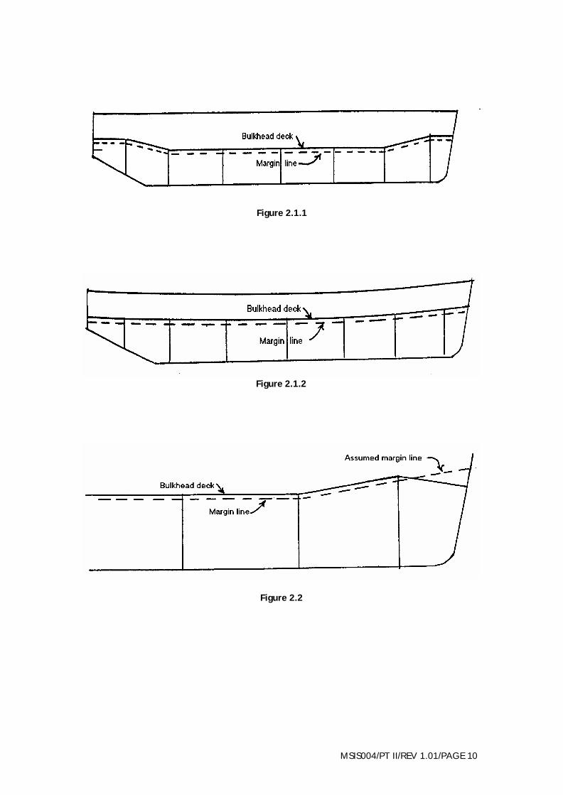
2.5.3.1 Definitions The following notes are for the guidance of surveyors in the interpretation of the definitions of subdivision terms given in Regulation 2(2) of Part I of the Regulations. 2.5.3.2 Margin line
(i) For a ship which has continuous bulkhead deck, the margin line is to be taken as a line drawn not less than 76mm below the upper surface of the bulkhead deck at side, except that where there is a variation in the thickness of the bulkhead deck at side the upper surface of the deck should be taken at the least thickness of deck at side above the beam. If desired however, the upper surface of the deck may be taken at the mean thickness of the deck side above the beam as calculated for the whole length of the deck, provided that the thickness is no greater than the least thickness plus 50mm (see figures 2.1.1 and 2.1.2). (ii) In case of Ro-Ro ferries where the vehicle deck slopes down forward of the collision bulkhead the margin line abaft collision bulkhead may be carried forward as an assumed line above the ramped portion of the vehicle deck (see figure 2.2). (iii) If the bulkhead deck is not continuous, a margin line should be assumed which is not at no point less than 76mm below the upper surface of the deck at side to which the bulkheads concerned and the shell plating are carried watertight, special attention being given to the requirements of paragraph 4(1)(d) of Section 2 of Schedule 2 of Merchant Shipping Notice MSN 1699(M) (see figure 2.3).
2.5.3.3 Floodable length
(i) To enable the permissible length of compartments to be determined in accordance with Section 2 of Schedule 2 to Merchant Shipping Notice MSN 1699(M) it is necessary to develop flooding curves which will indicate floodable length at any point in the ship’s length. (ii) Flooding curves should be developed by a method of calculation which takes into account the form, draught and other characteristics of the ship in question. (iii) Alternatively, equivalent damaged stability calculations may be accepted in lieu of the floodable Length Curves.
MSIS004/PT II/REV 1.01/PAGE 10
Figure 2.1.1
Figure 2.1.2
Figure 2.2

MSIS004/PT II/REV 1.01/PAGE 11
Figure 2.3
1. For compartments A, B, C and G the margin line Derived from Deck 1 may be used. For the remaining compartments the margin line derived from Deck 2 is to be used. The combined lengths C and D, F and G, and G and H are each not to exceed the permissible length determined by reference to the Deck 2 margin line. 2. Openings in the shell plating below Deck 1 in these areas of the ship are to comply with Regulation 13.
Figure 2.4 Steps in watertight bulkheads To illustrate paragraph 4.3 of Section 2 of Schedule 1 to
Merchant Shipping Notice MSN 1699 (M)
Dotted lines show transverse subdivision with plane bulkheads. Full lines show arrangement to compensate for step EFGHI and to maintain the same measure of safety.
ELEVATION
MSIS004/PT II/REV 1.01/PAGE 12
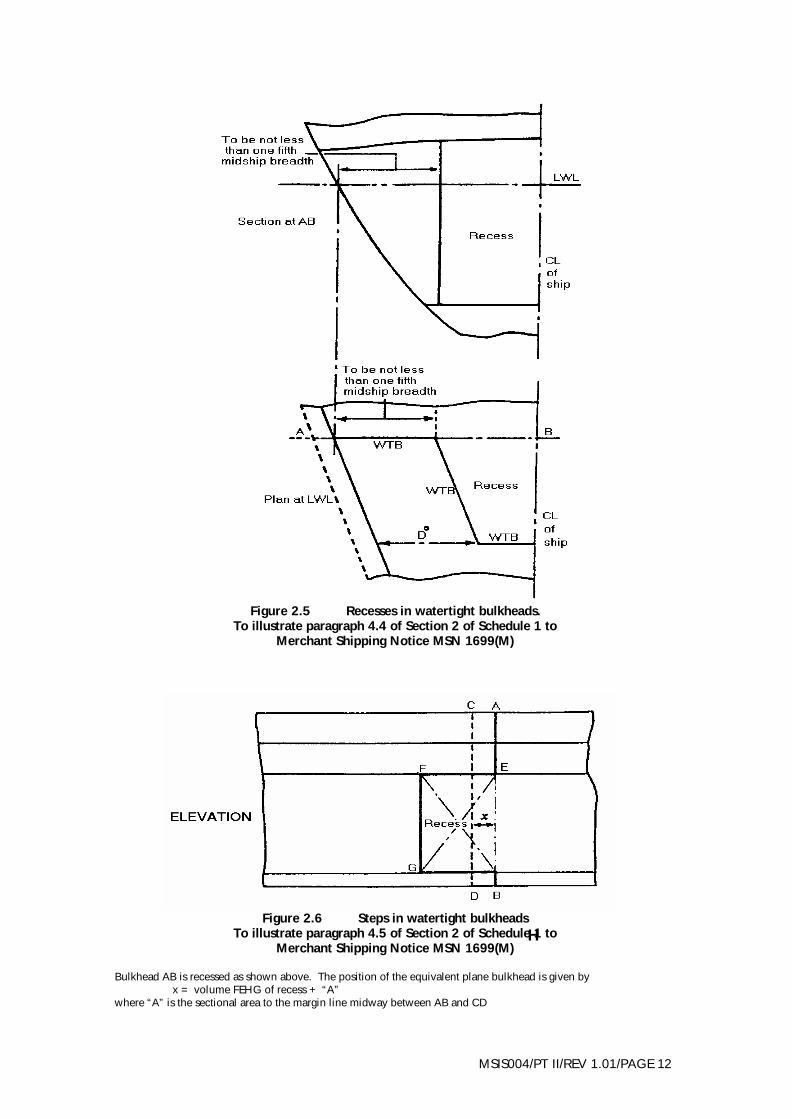
Figure 2.5 Recesses in watertight bulkheads.
To illustrate paragraph 4.4 of Section 2 of Schedule 1 to Merchant Shipping Notice MSN 1699(M)
Figure 2.6 Steps in watertight bulkheads
To illustrate paragraph 4.5 of Section 2 of Schedule 1 to Merchant Shipping Notice MSN 1699(M)
Bulkhead AB is recessed as shown above. The position of the equivalent plane bulkhead is given by x = volume FEHG of recess + “A” where “A” is the sectional area to the margin line midway between AB and CD
H

MSIS004/PT II/REV 1.01/PAGE 13
2.5.3.4 Permeability For the purpose of developing curves of floodable length average permeability’s referred to in paragraph 3 of the Section 2 of Schedule 2 are to be adhered to. 2.5.3.5 Passenger space Surveyors should note that as indicated in Schedule 2, Section 2, paragraph 1(4) to Merchant Shipping Notice MSN 1699(M) the expression “appropriated as accommodation for passengers” includes galleys, laundries and other similar spaces provided for the service of passengers, in addition to space provided for the use of passengers, but excludes baggage, store, provisions and mail room.
2.5.4 Special rules for subdivision Paragraph 4(1) of Section 2 of Schedule 2 to Merchant Shipping Notice MSN 1699(M) states the circumstances under which a compartment may exceed the permissible. In exceptional circumstances the MCA is prepared to consider any non-structural means of providing built-in buoyancy in compartments which do not achieve the required standard of subdivision providing such means are fitted inboard of the B/5 line and below the margin line. Such buoyancy should be fitted as high as possible in the compartment, especially if the stability of the ship is marginal when the compartment is assumed damaged. The MCA may require additional structural fire protection if a material used to provide built-in buoyancy is considered to be a fire hazard e.g. polyurethane foam.
2.5.4.1 Steps and recesses in bulkheads and equivalent plane bulkheads Paragraph 4 (3), 4(4) and 4 (5) of Section 2 of Schedule 2 to Merchant Shipping Notice MSN 1699(M) which deals with steps and recesses in bulkheads and equivalent plane bulkheads respectively, are illustrated by figures 2.4, 2.5 and 2.6 respectively. 2.5.4.2 Allowance for local subdivision
(i) Any claim for an allowance for local subdivision under the provisions of this paragraph should be accompanied by plans showing the proposed local subdivision and the volume of the main and sub-compartments concerned. No allowance should be made where these compartments are liable to be in open communication below the margin line through air, sounding or other pipes, or otherwise. (ii) The surveyor should satisfy himself on completion of the ship that this condition has been properly observed. (iii) In order to comply with paragraph 4(7) of Section 2 of Schedule 2 to Merchant Shipping Notice MSN 1699(M) the subdivision of multi-hull ships must be considered symmetrically i.e. compartments must be
MSIS004/PT II/REV 1.01/PAGE 14
assumed to be flooded in centre, port and starboard hulls at the same time. Corresponding bulkheads in each hull should normally be in the same longitudinal position. Where this is not compatible with the design, the shipbuilder should submit details of the measures which are to be adopted in order to maintain the same measure of safety presented by a plane bulkhead. (iv) Allowance under this sub-paragraph can be made only if such an allowance is not likely to prevent compliance with paragraph 3(2) of Schedule 3, Section 3 to Merchant Shipping Notice MSN 1699(M)
2.5.5 Verification of subdivisions particulars The floodable lengths are to be developed by an acceptable computer programme and: the surveyor is to ensure that the particulars are correct, and that the measurements which make up the computer input data correspond to the ship as building, and adequately define the volumes used in the computation. It may be helpful for the surveyor to be present when the input data is being compiled by the shipbuilder who should be informed that, in the event of any alteration in the lines plan after the form particulars and input data have been verified, they should be revised immediately, re-checked by the surveyor and the flooding curves amended accordingly. 2.5.6 Verification of watertight subdivision arrangements When the watertight subdivision arrangements have been accepted, the surveyor should satisfy himself that the accepted arrangements are provided in the ship. The procedure described below should generally be followed:
2.5.6.1 Spacing of watertight bulkheads
The positions of the main transverse bulkheads should be noted from the accepted subdivision plans. These positions should be checked at the ship, together with those of the accepted steps and recesses in the watertight bulkheads, and the arrangements of the longitudinal watertight and non-watertight bulkheads. 2.5.6.2 Appropriation of spaces
The surveyor should examine each such space, and satisfy himself that it has been fitted out in accordance with the appropriation of spaces upon which the calculations for average permeabilities, and criterion of service numeral, have been calculated, and as shown on the accepted plans. If it appears that a space will be used for another purpose, which would involve a higher average permeability throughout the portion of the ship in which the space is situated, or an increase in the criterion of service numeral, the surveyor should draw the

MSIS004/PT II/REV 1.01/PAGE 15
attention of then builders to the matter, and ensure that the calculations are amended accordingly. 2.5.6.3 Survey of watertight subdivision arrangements before painting, etc. The provisions of paragraph 2.2.3 of these Instructions apply also to the first survey of watertight bulkheads, etc., and the surveyor should take similar actions if these are painted, cemented or otherwise coated before he has examined them. Particular care should be exercised by the surveyor to satisfy himself that the integrity of the watertight subdivision, where pipes, cables, etc. pass through steps or recesses in watertight bulkheads, is not impaired. 2.5.6.4 File records On completion of the ship, the surveyor should ensure that all the necessary particulars are recorded in the ship’s files.
2.6 Peak and Machinery Space Bulkheads, Shaft Tunnels (Regulation 9) 2.6.1 Extension to collision bulkhead
2.6.1.1 The plating and stiffeners to an extension of the collision bulkhead above the margin line shall be constructed as if the extension formed part of a bulkhead immediately below the bulkhead deck. 2.6.1.2 In ships fitted with a bow ramp to facilitate the loading and/or unloading of vehicles at the fore end, the MCA may accept such a ramp as the extension to the collision bulkhead in compliance with Regulation 9(1), noting that for ships constructed on or after 1 September 1998, Regulation 9(4) shall be complied with. Details of the position, construction and means of making the ramp weathertight should be submitted for consideration.
2.6.2 Shaft tunnels
2.6.2.1 The watertight shaft tunnel, or other watertight space in which the stern gland is to be situated, should be of sufficient height and width to allow proper attention to be given to shaft couplings, bearings etc. within the space. 2.6.2.2 The stern tube should be enclosed in a watertight compartment, the volume of which should be the smallest compatible with the proper design of the ship.
2.7 Weather Deck (Regulation 10) The bulkhead deck is only required to be weathertight when it is not protected by a higher deck which is weathertight. However, in ships where the bulkhead deck is so protected, the portion of deck which forms the step between the fore peak

MSIS004/PT II/REV 1.01/PAGE 16
bulkhead and its extension, when they are not in line, is still required to be weathertight in accordance with Regulation 9(1), and the portion of deck which forms the step between a main subdivision bulkhead and a partial bulkhead or web, fitted to limit the spread of water along the deck, is still required to be watertight in accordance with Regulation 11. 2.8 Partial Subdivision Above the Bulkhead Deck (Regulation 11) 2.8.1 General If the margin line is submerged during the flooding of one or more compartments within the extent of damage outlined in Section 1 of Schedule 3 of Merchant Shipping Notice MSN 1699(M), means shall be provided to limit the spread of water along the bulkhead deck to a minimum, and help to maintain positive stability through all stages of flooding. 2.8.2 Partial bulkheads and webs If partial watertight bulkheads or webs are fitted to provide such means, they should be fitted immediately above the main subdivision bulkheads of the damaged compartment or compartments, or as close to them as possible, but not in such a position that they could be involved in the damage. Such partial bulkheads or webs should extend inboard from the ship's side, to at least the point of intersection between a line drawn parallel to, and 76mm above, the heeled waterline and the bulkhead deck. This heeled waterline is the one which extends furthest inboard, at the longitudinal position of the partial bulkhead or web during the flooding of the compartment or compartments. The plating and stiffeners of partial bulkheads or webs are to be constructed in accordance with Schedule 4 to Merchant Shipping Notice MSN 1699(M), as if they formed part of the bulkhead immediately below the bulkhead deck. (See figure 2.7) 2.8.3 Fire resisting bulkheads In ships where fire resisting bulkheads forming the boundaries of main vertical zones are fitted on the bulkhead deck, such bulkheads, together with any additional bulkheads or webs which are considered necessary, may be accepted as complying with Regulation 11 providing they are suitably positioned, and any openings in them are above the line defined in the preceding paragraph. 2.8.4 Alternative means
2.8.4.1 In ships which, due to their particular service, are not fitted with bulkheads on the bulkhead deck, the MCA is prepared to consider any alternative means for limiting the spread of water along the bulkhead deck. 2.8.4.2 In ships where it is not intended to fit any means to limit the spread of water along the bulkhead deck, the damage stability calculations must show that the margin line is not submerged at any stage of flooding.

MSIS004/PT II/REV 1.01/PAGE 17
2.8.4.3 In order to show that progressive flooding cannot take place when the margin line is submerged, a trace of the line to which the water extends furthest inboard during any stage of flooding should be shown on a plan of the bulkhead deck which indicates the partial subdivision arrangements, and the position of openings in the deck and bulkheads. If air and overflow pipes terminate on the bulkhead deck, the trace should also be shown on a profile to show that progressive flooding cannot take place through the pipes.
Figure 2.7 Partial subdivision above the bulkhead deck
To illustrate paragraph 2.8.2
MSIS004/PT II/REV 1.01/PAGE 18
2.9 Openings in Watertight Bulkheads Below the Bulkhead Deck (Regulation 12) 2.9.1 General
2.9.1.1 In view of the nature of the services in which ships of Classes III to VI(A) are engaged Regulation 12 states that subdivision watertight bulkheads in such ships are not to be pierced by doorways, ventilation trunks or similar openings unless such openings are essential for the proper working of the ship and do not impair the ships' survivability standard. When such openings are proposed, full particulars as to their purpose, construction and the means of closing them are submitted to the MCA for consideration. 2.9.1.2 In order to maintain the integrity of the watertight bulkheads in the event of damage, valves which are fitted in piping systems should, in the case of ships constructed on or after 1 September 1998, also be screw-down valves capable of being controlled manually at the valve, and from a position above the bulkhead deck by means of extended spindles. 2.9.1.3 On Class III vessels the spindles and controls to such valves should be fitted inboard of the B/5 line, but in ships such as vehicle ferries, with casings on the bulkhead deck outboard of the B/5 line, the MCA will permit the spindles and controls to be taken to casings outboard of the B/5 line providing they are positioned on the side of the bulkhead which provides the greater protection, and kept as close to the bulkhead as possible. 2.9.1.4 The MCA may consider any alternative means of controlling the valves, and if it is from a central control, it must be such that damage to any valve or operating equipment within the extent of damage specified in paragraph 1(3) of Section 1 of Schedule 3 to Merchant Shipping Notice MSN 1699(M) does not render the system inoperable in the remaining intact portion of the ship. The system should also be such that the valves will automatically close if the means of operating them fails. 2.9.1.5 The MCA will not permit the use of plastics for piping systems which pierce subdivision bulkheads, or for valves in such systems, unless it can be proved beyond doubt that such plastics are not heat sensitive. 2.9.1.6 If it is intended to use any other material which the surveyor may consider to be heat sensitive, for piping and/or parts of valves which maintain the integrity of the watertight bulkheads, full details should be submitted by the shipbuilder for consideration.
2.9.2 Position of watertight doors
2.9.2.1 Watertight doors, when permitted, should be fitted inboard of the B/5 line and with their sills as high as possible above the keel. The MCA may

MSIS004/PT II/REV 1.01/PAGE 19
permit a door to be positioned outboard of the B/5 line if satisfied that it is necessary for the proper working of the ship and cannot be located elsewhere. 2.9.2.2 Where watertight doors are permitted to be fitted in bulkheads dividing two between deck cargo spaces they must be located inboard of the B/5 line. 2.9.2.3 Detailed information regarding the construction, installation, operation and testing of watertight doors, and the requirements for signals and communications are contained in Part III of these Instructions.
2.10 Openings in the Shell Plating Below the Bulkhead Deck (Regulation 13) 2.10.1 General requirements The general requirements for openings in the shell plating below the bulkhead deck, and their means of closing, are set out in Regulation 13, and Schedule 10 to Merchant Shipping Notice MSN 1699(M). 2.10.2 Side scuttles
2.10.2.1 Side scuttles fitted in ships of Class III should comply with BSMA 24 or equivalent. Details of any side scuttle which does not comply should be submitted for consideration see Part II to these Instructions. 2.10.2.2 In the case of ships of Classes IV to VI, such modifications of the requirements of the British Standard specification as appear reasonable may be allowed, having regard to the intended service of the ship. 2.10.2.3 The arrangements of side scuttles should be re-examined when an increase in draught is proposed, and any side scuttles which lie below a line either 2.5 per cent of the breadth of the ship, or 500mm, whichever is the greater, above the new subdivision load waterline, must be blanked off. 2.10.2.4 The requirements of Regulation 13(3) are illustrated by figures 2.8.1 and 2.8.2.
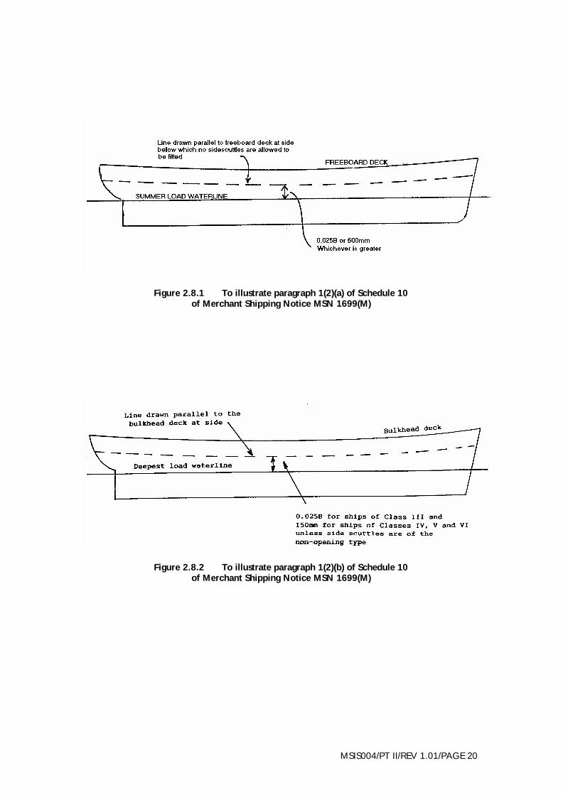
MSIS004/PT II/REV 1.01/PAGE 20
Figure 2.8.1 To illustrate paragraph 1(2)(a) of Schedule 10 of Merchant Shipping Notice MSN 1699(M)
Figure 2.8.2 To illustrate paragraph 1(2)(b) of Schedule 10 of Merchant Shipping Notice MSN 1699(M)
MSIS004/PT II/REV 1.01/PAGE 21
2.10.3 Inlets and discharges
2.10.3.1 Regulation 13(3) and Schedule 10 to Merchant Shipping Notice MSN 1699(M) requires for every subdivided ship that each inlet and discharge led through the shell below the bulkhead deck shall be arranged so as to prevent the accidental admission of water into the ship. 2.10.3.2 In order to satisfy these requirements, and those of the International Convention on Load Lines where applicable, inlets and discharges led through the shell below the bulkhead deck should be arranged as follows:-
(i) Each inlet and discharge led through the shell below the bulkhead deck shall be fitted with efficient and readily accessible means for preventing the accidental admission of water into the ship. (ii) Lead or other heat sensitive materials shall not be used in any other place where the deterioration of such pipes in the event of a fire would give rise to the danger of flooding.
2.10.3.3 Each discharge led through the shell from any space below the bulkhead deck, not being a discharge in connection with machinery, shall be provided with:
(i) one automatic non-return valve fitted at the shell of the ship and having positive means of closure from a position or positions above the bulkhead deck or, in a ship which is marked with a summer load line, from a position or positions above the bulkhead deck or the freeboard deck, whichever is the higher. Such positions shall be readily accessible at all times under service conditions. The means of closure shall be provided with an indicator showing whether the valve is open or closed; or (ii) two automatic non-return valves having no positive means of closure where the vertical distance from the inboard end of the discharge pipe in which those valves are fitted to the summer load waterline exceeds 0.0lL, (where L is the length of the ship as defined in the Merchant Shipping (Load Lines) Regulations 1998; in any ship which is not marked with a summer load waterline the vertical distance shall be measured to the ship’s deepest subdivision load waterline; one such valve shall be situated as close to the ship's shell as practicable and substantially connected thereto and the inboard valve shall where practicable be fitted above the deepest load waterline; where that is not practicable a locally controlled sluice valve interposed between the two automatic non-return valves shall be fitted; the inboard valve shall in every case be in such a position that it will at all times under service conditions be readily accessible for examination. The requirements of the Merchant Shipping (Load Line) Regulations 1998 shall apply to discharges led through the shell plating from spaces above the bulkhead deck.

MSIS004/PT II/REV 1.01/PAGE 22
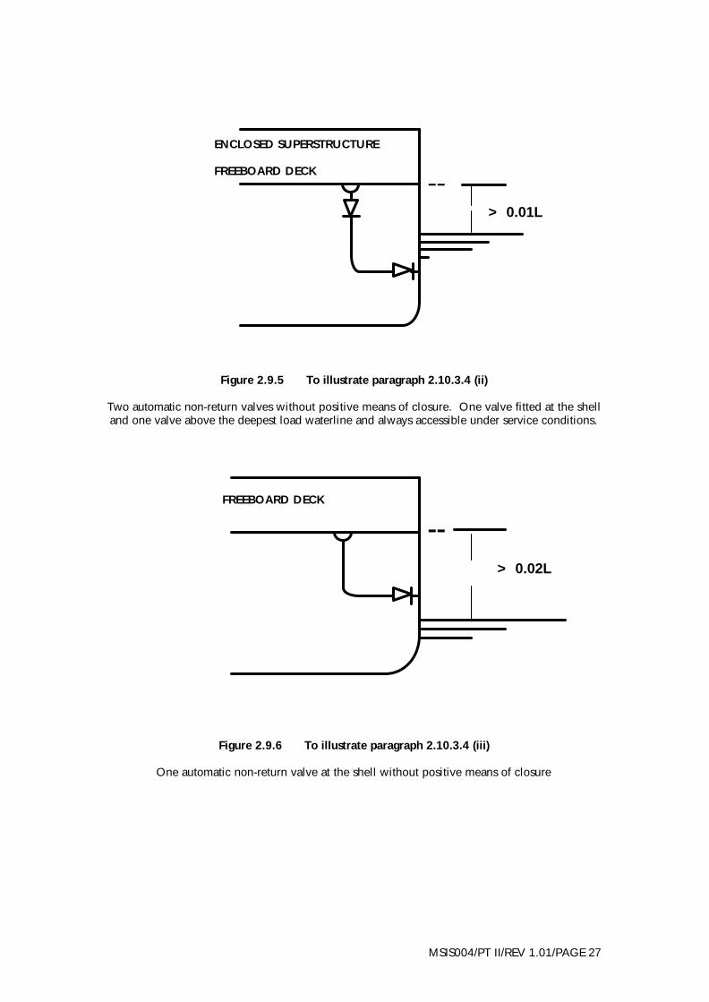
2.10.3.4 In every ship which is marked with a summer load line every discharge led through the shell below the bulkhead deck from any space above the bulkhead deck, other than an enclosed cargo space situated on the bulkhead deck, being a space below the freeboard deck or from within any enclosed superstructure or from within any deckhouse on the freeboard deck which is fitted with doors, not being a discharge in connection with machinery, shall be fitted with either:
(i) one automatic non-return valve fitted in compliance with the requirements of sub-paragraph (i) of paragraph 2.10.3.3; or (ii) two automatic non-return valves fitted in compliance with the requirements of sub-paragraph (ii) of paragraph 2.10.3.3; or (iii) one automatic non-return valve having no positive means of closure in any ship where the vertical distance from the summer load waterline to the inboard end of the discharge pipe exceeds 0.02L, (where L is the length of the ship as defined in the Merchant Shipping (Load Lines) Regulations 1998). Such valve shall be situated as close to the ship's shell as practicable and substantially connected thereto.
2.10.4 Drainage from cargo spaces
2.10.4.1 Ships constructed before 1 February 1992 In every ship which is marked with a summer load line efficient drainage from any enclosed cargo space on the bulkhead deck shall be provided. Every discharge shall be in compliance with the requirements of paragraph 2.10.3 provided that where the freeboard to the bulkhead deck is such that the deck edge is immersed when the ship heels 5° either way, other arrangements shall be provided to drain such spaces which shall be to the satisfaction of the Secretary of State, provided that the Secretary of State may permit the means of drainage to be dispensed with in any particular compartments of any ship if he is satisfied that by reason of the size or internal subdivision of those spaces, the safety of the ship is not thereby impaired. 2.10.4.2 Ships constructed on or after 1 February 1992
(i) Provision shall be made for the drainage of enclosed cargo spaces on the bulkhead deck; however the means of discharge may be dispensed with in any particular compartment of any ship if by reason of size or internal subdivision of those spaces the safety of the ship is not thereby impaired. (ii) Where the freeboard to the bulkhead deck is such that the deck edge is immersed when the ship heels more than 5°, the drainage shall be by means of a sufficient number of scuppers of suitable size discharging
MSIS004/PT II/REV 1.01/PAGE 23
directly overboard. Every discharge shall be in compliance with the requirements of paragraph 2.10.3. (iii) Where the freeboard is such that the edge of the bulkhead deck is immersed when the ship heels 5° or less, the drainage of the enclosed cargo spaces on the bulkhead deck shall be led to a suitable space, or spaces, of adequate capacity, having a high water level alarm and provided with suitable arrangements for discharge overboard. In addition it shall be ensured that:-
(a) the number, size and disposition of the scuppers are such as to prevent unreasonable accumulation of free water; (b) the pumping arrangements required by this regulation shall take account of the requirements for any fixed pressure water-spraying fire-extinguishing system; (c) water contaminated with petrol or other dangerous substances is not drained to machinery spaces or other spaces where sources of ignition may be present; and (d) where the enclosed cargo space is protected by a carbon dioxide fire-extinguishing system the deck scuppers are fitted with means of prevent escape of the smothering gas.
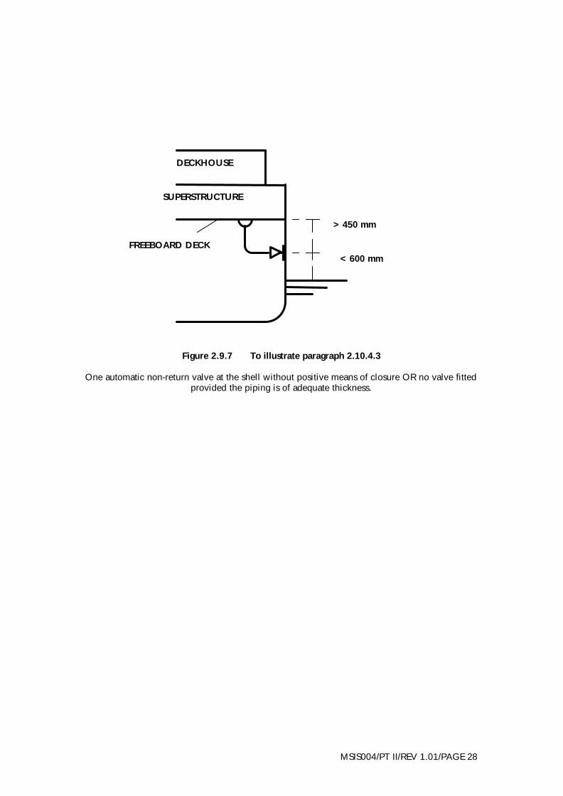
2.10.4.3 In every ship, constructed on or after 1 February 1992, which is marked with a summer load line every scupper and discharge originating at any level above those described in sub-paragraphs above and penetrating the shell of the ship either -
(i) more than 450mm below the freeboard deck; or (ii) less than 600mm above the summer load waterline shall be equipped with an automatic non-return valve situated as close to the ship's shell as practicable and substantially connected thereto provided that this sub-paragraph shall not apply:
(a) where the scupper or discharge pipe is fitted with means for preventing water from passing inboard in accordance with the provisions of the above sub-paragraphs; or (b) in any case in which the piping of the scupper, or discharge pipe is of adequately increased thickness.
2.10.4.4 All cocks and valves attached to inlets or discharges, other than inlets or discharges connected with machinery, the failure of which may give rise to the danger of flooding, shall be made of steel, bronze or other equivalent material.

MSIS004/PT II/REV 1.01/PAGE 24
2.10.4.5 Inlets and discharges connected with main or auxiliary machinery shall be fitted with cocks or valves between the pipes and the shell of the ship or between the pipes and a box attached to the shell. The controls to such cocks and valves or of any bilge injection system shall be readily accessible at all times under service conditions and fitted with indicators to show whether the cock or valve is open or closed. All such cocks or valves attached to such inlets or discharges and all fittings outboard thereof shall be made of steel, bronze or other equivalent material. If made of steel, such cocks and valves shall be protected against corrosion. 2.10.4.6 Discharge pipes led through the shell below the bulkhead deck of any ship to which these Instructions apply shall not be fitted in a direct line between the outboard opening and the connection with a deck, water closet or other similar fitting, but shall be arranged with bends or elbows of substantial metal other than cast iron or lead. 2.10.4.7 All discharge pipes led through the shell below the bulkhead deck and the valves relating thereto shall be protected from damage. 2.10.4.8 Efficient means shall be provided for the drainage of all watertight decks below the bulkhead deck and any drainage pipes shall be so fitted with valves or otherwise arranged as to avoid the danger of water passing from a damaged to an undamaged compartment. 2.10.4.9 The Requirements of Schedule 10 and the foregoing paragraphs are illustrated by figures 2.9.1 to 2.9.7. 2.10.4.10 All discharge pipes fitted in accordance with the requirements of this paragraph should have a sufficient bend to provide for expansion of the pipe and any movement due to working of the ship. 2.10.4.11 The arrangements of scuppers and discharges should be re-examined when an increase in draught is proposed, and where such an increase warrants a more positive means of preventing water from passing inboard, such means must be fitted to the scuppers and discharges.
2.10.5 Gangway and loading openings Gangway and loading openings are to satisfy Schedule 10, paragraph 3 of Merchant Shipping Notice MSN 1699(M). 2.10.6 Water-closets When water-closets of the under-waterline type are to be fitted, plans should be specially submitted for acceptance.

MSIS004/PT II/REV 1.01/PAGE 25
Figure 2.9.1 To illustrate paragraph 2.10.3.3(i)
One automatic non-return valve at the shell with positive means of closure above the bulkhead or freeboard deck and fitted with open/shut indicator
Figure 2.9.2 To illustrate paragraph 2.10.3.3(ii)
Two automatic non-return valves without positive means of closure. One valve fitted at the shell and one valve above the deepest load waterline and always accessible under service conditions
FREEBOARD DECK
OR BULKHEAD DECK WHICHEVER IS HIGHEST
>0.01L
FREEBOARD DECK
OR BULKHEAD DECK

MSIS004/PT II/REV 1.01/PAGE 26
Figure 2.9.3 To illustrate paragraph 2.10.3.3(ii) Alternative arrangement
Two automatic non-return valves without positive means of closure, one of which is fitted at the shell, and a readily accessible locally controlled sluice valve fitted between the two non-return
valves
Figure 2.9.4 To illustrate paragraph 2.10.3.4(i)
One automatic non-return valve at the shell with positive means of closure above the freeboard deck and fitted with open/shut indicator
>0.01L
FREEBOARD DECK
OR BULKHEAD DECK
ENCLOSED SUPERSTRUCTURE FREEBOARD DECK
MSIS004/PT II/REV 1.01/PAGE 27
Figure 2.9.5 To illustrate paragraph 2.10.3.4 (ii)
Two automatic non-return valves without positive means of closure. One valve fitted at the shell and one valve above the deepest load waterline and always accessible under service conditions.
Figure 2.9.6 To illustrate paragraph 2.10.3.4 (iii)
One automatic non-return valve at the shell without positive means of closure
> 0.01L
ENCLOSED SUPERSTRUCTURE FREEBOARD DECK
FREEBOARD DECK
> 0.02L
MSIS004/PT II/REV 1.01/PAGE 28
Figure 2.9.7 To illustrate paragraph 2.10.4.3
One automatic non-return valve at the shell without positive means of closure OR no valve fitted provided the piping is of adequate thickness.
<600 mm
>450 mm
DECKHOUSE
SUPERSTRUCTURE
FREEBOARD DECK

MSIS004/PT II/REV 1.01/PAGE 29
2.10.7 Storm valves The storm valves fitted at the ship's side are to be of a substantial back-balanced type, or of a type in which the valve face is at an angle of not less than 15o to the vertical when closed. The MCA is prepared to accept the valve mounted on a spigot, instead of being attached directly to the shell, providing that the spigot is not more than 305mm in length, is efficiently welded and bracketed to the shell, and its thickness is not less than the thickness of the shell plating in which it is situated. 2.10.8 Closure versus heel In all ships, the incidence of the calculations made under the provisions of Schedule 3 to Merchant Shipping Notice MSN 1699(M), relating to stability and angle of heel in the damaged condition, will be taken into account by the MCA in accepting the means of closing scuppers, discharges and other side openings from spaces above the margin line. 2.11 Side and Other Openings Above the Bulkhead Deck (Regulation 14) 2.11.1 Side scuttles Surveyors should note that the provision of paragraph 2.10.2 also applies, in the case of subdivided ships, to side scuttles fitted to openings in the ship's sides above the bulkhead deck. 2.11.2 Windows in the ship’s side and superstructures Window sizes should normally be not greater than those given in BSMA 25:1973. However, the MCA may accept windows the sizes of which are greater having regard to the particular characteristics of the ship and its area of operations. The MCA may require the glass in such windows to be thicker than the maximum thickness given in the British Standard specification. 2.11.3 Deadlights
2.11.3.1 In The following requirements apply to any subdivided ship of Classes III to VI(A), subject to such modifications as appear reasonable having regard to the intended service of the ship
(i) In enclosed spaces in every subdivided ship efficient hinged deadlights which can be effectively closed and secured watertight must be fitted to all side scuttles located below the first deck above the bulkhead deck or freeboard deck, whichever is the higher. (ii) In other enclosed superstructures, side scuttles and windows should be provided with deadlights or shutters, which may be fixed or portable, except that only fixed deadlights or shutters should be fitted to side scuttles

MSIS004/PT II/REV 1.01/PAGE 30
and windows situated in the bridge front of the 1st tier of superstructures immediately above the weather-deck. Portable dead-lights and shutters should be provided to the extent shown in the following table:- Tier of superstructure above the bulkhead deck or freeboard deck, whichever is the higher
Required number of portable deadlights or shutters, expressed as a percentage of the total number of side scuttles or windows of each type or size, excluding those fitted with fixed deadlights or shutters
2nd tier 3rd tier 4th tier and higher tiers
50% 25% May be required, subject to consideration
2.11.3.2 Shutters should be of steel of not less than 3.5mm in thickness, or of an equivalent material, and provided with means of securing them to the frame sufficient to withstand the pressures likely to be experienced in service.
2.11.4 Glass for side scuttles and windows
2.11.4.1 The glass for side scuttles and windows fitted in all ships should be in accordance with paragraph 2.3.3 of these Instructions, and those thicknesses may be reduced by the MCA for side scuttles and windows fitted in ships of Classes III to VI(A), depending on the size and position of such side scuttles and windows. 2.11.4.2 The number of spare glasses which are to be provided for the side scuttles and windows should be not less than 4 per cent of the total number of glasses for each size fitted, with a minimum number of 2 glasses for each size.
2.11.5 Drainage of vehicle spaces 2.11.5.1 In vehicle ferries or similar ships with large open or enclosed spaces, means should be provided to free rapidly such spaces of water which may have accidentally entered the ship, or may be present as a result of operating a fire extinguishing system, because of the adverse effect of such water on stability. 2.11.5.2 Normally, scuppers of 152mm diameter should be fitted on each side of such an enclosed space, and spaced not more than 9.15m apart when the maximum breadth of the deck in the space is 18.3m or less. When the maximum breadth is in excess of 18.3m, the scupper should be decreased in direct proportion to the maximum breadth to 18.3m.

MSIS004/PT II/REV 1.01/PAGE 31
2.11.5.3 In ships having ramped vehicle decks or unusual sheer on the deck the number and spacing of the scuppers will require to be determined having regard to such features. 2.11.5.4 If the scuppers are fitted with valves having positive means of closure, the position for operating such means should be accessible from outside the vehicle spaces and above the bulkhead deck. 2.11.5.5 The efficiency of the scuppers should not be impaired by kerbs, fenders, etc., and openings in gratings should be sufficiently large to prevent them becoming choked by rubbish. 2.11.5.6 Before the ship is permitted to enter into service the efficiency of the scupper arrangements is to be demonstrated to show that there is no build-up of water on any portion of the deck and that the deck is rapidly cleared of water. For the purpose of this test the surveyor should ensure that as many sections of the fire extinguishing system as deemed necessary are operated simultaneously with not less than two fire hydrants for as long a period of time as needed to show that the above requirements have been complied with. 2.11.5.7 If any build-up of water occurs during the test the surveyor should discuss with the builders where additional scuppers need to be provided. After the necessary modifications to the scupper arrangements have been carried out the above test should be repeated. 2.11.5.8 In the case of a ship where the scuppers discharge below the deepest subdivision load waterline the ship should ideally be at this deepest draught at the time of the test. Where it is not possible to ballast the ship to this draught due regard should be paid to the reduction in the rate at which water will flow down the scupper pipes in the fully loaded condition due to the increased back pressure caused by the submergence or additional submergence of the discharge through the ship's side in that condition compared with the condition at the time of the test. 2.11.5.9 Only when the surveyor is satisfied with the results of the test should the ship be permitted to enter into service. 2.11.5.10 The freeing arrangements for open spaces will be specially considered by the MCA in view of the greater risk which they present and, if it is considered that such spaces could hazard the safety of the ship, they should be enclosed.