street planning and design criteria
TRANSCRIPT

TRANSPORTATION
Section 6-3
STREET PLANNING AND DESIGN
CRITERIA
The Town Of Buckeye Arizona
Engineering Design Standards Section 6-3 Adopted December 2012

Section 6-3 STREET PLANNING AND DESIGN CRITERIA
Town of Buckeye December 2012 Page 1
TABLE OF CONTENTS 6-3.000 GENERAL INFORMATION:..............................4
6-3.001 STREET PLANNING AND DESIGN CRITERIA REQUIREMENTS:............................................. 4
6-3.002 DEFINITIONS AND ABBREVIATIONS: ..................... 4 6-3.003 DESIGN POLICY: .............................................. 6 6-3.004 DILIGENCE: ..................................................... 6 6-3.005 IMPLEMENTATION: ........................................... 7 6-3.006 PRIVATE STREETS: ............................................ 7 6-3.007 STORM WATER POLLUTION PREVENTION PLAN
(SWPPP): .................................................... 8 6-3.008 STANDARDS: ................................................... 8
6-3.100 STREET CLASSIFICATIONS: .............................9
6-3.101 GENERAL INFORMATION: .................................. 9 6-3.102 FREEWAYS: ..................................................... 9 6-3.103 PARKWAYS: .................................................... 9 6-3.104 MAJOR ARTERIAL: ......................................... 10 6-3.105 ARTERIAL AND MAJOR COLLECTOR: ................... 10 6-3.106 COLLECTOR: ................................................. 10 6-3.107 MAJOR LOCAL: .............................................. 10 6-3.108 LOCAL: ........................................................ 11 6-3.109 COMMERCIAL COLLECTOR ............................... 11 6-3.110 RESIDENTIAL ENTRANCE .................................. 11
6-3.200 STREET DESIGN CRITERIA: ........................... 11
6-3.201 CROSS SECTIONS: .......................................... 11 6-3.202 LANE WIDTHS: .............................................. 11 6-3.203 STREET ROW: .............................................. 12 6-3.204 PUBLIC UTILITY EASEMENTS (PUE): .................. 12 6-3.205 PAVEMENT CROSS-SECTION SLOPES: ................. 12 6-3.206 MEDIANS: .................................................... 15 6-3.207 CURBS: ........................................................ 16 6-3.208 CURB RETURNS: ............................................ 18 6-3.209 CURB RAMPS: ............................................... 18 6-3.210 DESIGN SPEED: ............................................. 20 6-3.211 SUPER-ELEVATION IN CURVES: ......................... 20 6-3.212 HORIZONTAL CURVES: .................................... 21 6-3.213 MINIMUM RADII OF CURVATURE: ..................... 21 6-3.214 CONSIDERATION OF STOPPING SIGHT DISTANCE: . 21 6-3.215 REDUCED DESIGN SPEEDS ON CURVES: .............. 22 6-3.216 COMPOUND CURVES: ..................................... 22 6-3.217 TANGENT SECTIONS BETWEEN CURVES IN THE SAME
DIRECTION: ................................................. 23 6-3.218 TANGENT SECTIONS BETWEEN REVERSE CURVES: . 23 6-3.219 TANGENT SECTIONS APPROACHING INTERSECTIONS:
................................................................. 23 6-3.220 LONGITUDINAL STREET GRADES: ....................... 23 6-3.221 VERTICAL CURVES: ......................................... 23
6-3.222 COMBINED HORIZONTAL AND VERTICAL CURVES: 25
6-3.300 INTERSECTIONS: .......................................... 27
6-3.301 GENERAL INTERSECTION CRITERIA: ....................27 6-3.302 INTERSECTION SPACING: .................................27 6-3.303 ANGLE OF INTERSECTION: ................................28 6-3.304 ALIGNMENT AND PROFILE: ..............................28 6-3.305 INTERSECTION CROSS SLOPES ...........................28 6-3.306 INTERSECTION AND DRIVEWAY SIGHT DISTANCE: .28 6-3.307 SIGHT VISIBILITY TRIANGLES (SVT): ...................30 6-3.308 INTERSECTIONS WITH AN UNPAVED LEG: ............31 6-3.309 VALLEY GUTTERS AT STREET INTERSECTIONS: ......31 6-3.310 AUXILIARY LANES: ..........................................32 6-3.311 MEDIAN DESIGN: ..........................................32 6-3.312 TRAFFIC CONTROL: ........................................33
6-3.400 STREET ACCESS AND DRIVEWAYS: ............... 34
6-3.401 DRIVEWAY SPACING: ......................................34 6-3.402 DRIVEWAY LOCATION LIMITATIONS: ..................35 6-3.403 PROTECTION OF ACCESS: .................................35 6-3.404 RESIDENTIAL DEVELOPMENT DRIVEWAYS: ..........35 6-3.405 COMMERCIAL AND INDUSTRIAL DEVELOPMENT
DRIVEWAYS: ................................................36
6-3.500 SIDEWALKS: ................................................ 36
6-3.501 SIDEWALK STANDARDS: ..................................37
6-3.600 ROUNDABOUTS: ......................................... 37
6-3.601 GENERAL REQUIREMENTS:...............................38 6-3.602 DESIGN CONSIDERATIONS:...............................39
6-3.700 BRIDGES, RETAINING WALLS, STRUCTURAL CLEARANCES AND SIDE SLOPES: ................. 40
6-3.701 BRIDGES: .....................................................40 6-3.702 RETAINING WALLS: ........................................41 6-3.703 STRUCTURAL CLEARANCES: ..............................42 6-3.704 VERTICAL CLEARANCE: ....................................43 6-3.705 SIDE SLOPES: ................................................43
6-3.800 HALF STREET CONSTRUCTION: .................... 43
6-3.801 PARTIAL STREET CONSTRUCTION: ......................43 6-3.802 CONSTRUCTION OF HALF-STREETS: ...................43
6-3.900 PAVEMENT TRANSITIONS: .......................... 45
6-3.901 GENERAL REQUIREMENTS:...............................45 6-3.902 FRONTAGE ROADS: ........................................45
6-3.1000 SUBDIVISION STREET PLANNING: ................ 46
Section 6-3 STREET PLANNING AND DESIGN CRITERIA
Town of Buckeye December 2012 Page 2
6-3.1001 GENERAL REQUIREMENTS: .............................. 46 6-3.1002 ALLEYS: ....................................................... 48 6-3.1003 OFFSET INTERSECTIONS: .................................. 49 6-3.1004 INTERSECTION TANGENTS: ............................... 49
6-3.1100 HILLSIDE DEVELOPMENT STREET STANDARDS: ................................................................. 49
6-3.1101 GENERAL REQUIREMENTS: .............................. 49
6-3.1200 PLAN PREPARATION: ................................... 55
6-3.1201 GENERAL REQUIREMENTS: .............................. 55 6-3.1202 DESIGN PLAN REQUIREMENTS: ......................... 55 6-3.1203 SUBMITTAL REQUIREMENTS: ............................ 57 6-3.1204 TOWN OF BUCKEYE PERMIT: ............................ 58
6-3.1300 MATERIALS: ................................................ 58
6-3.1301 SUBMITTALS: ................................................ 58 6-3.1302 MATERIALS:.................................................. 58
6-3.1400 AS-BUILT DRAWINGS: ................................. 59
6-3.1401 GENERAL REQUIREMENTS: .............................. 59 6-3.1402 “TO PAVE” AS-BUILT DRAWINGS: .................... 59 6-3.1403 “FINAL” AS-BUILT DRAWINGS: ........................ 59 6-3.1404 TOLERANCES AND CORRECTIONS: ...................... 60
TABLE OF FIGURES FIGURE 1 DIMENSION FROM LIP TO FLOW LINE ..................... 14 FIGURE 2 MEDIAN GRADING .............................................. 15 FIGURE 3 VIEW OBSTRUCTIONS AND HORIZONTAL CURVES ...... 22 FIGURE 4 MINIMUM CREST VERTICAL CURVE LENGTH
DETERMINED BY STOPPING SIGHT DISTANCE ........... 26 FIGURE 5 MINIMUM CREST VERTICAL CURVE LENGTH
DETERMINED BY PASSING SIGHT DISTANCE ............. 26 FIGURE 6 MINIMUM SAG VERTICAL CURVE LENGTH DETERMINED
BY STOPPING SIGHT DISTANCE .............................. 27 FIGURE 7 MINIMUM SAG VERTICAL CURVE LENGTH DETERMINED
BY COMFORT FACTORS........................................ 27 FIGURE 8 INTERSECTION/DRIVEWAY SIGHT DISTANCE
REQUIREMENTS ................................................. 29 FIGURE 9 SIGHT VISIBILITY TRIANGLES ................................. 31 FIGURE 10 MEDIAN OPENING FOR INTERSENTIONS .................. 33 FIGURE 11 SUBDIVISION STREET PLANNING ........................... 46 FIGURE 12 CUL-DE-SAC ..................................................... 47 FIGURE 13 KNUCKLES AND EYEBROWS .................................. 48 FIGURE 14 ALLEY WIDTHS AND INTERSECTIONS ...................... 49
TABLE OF TABLES TABLE 1 STREET DESIGN ELEMENTS ...................................13 TABLE 2 MINIMUM CURB RETURN RADII AND ROW CLIP ......19 TABLE 3 MINIMUM ‘K’ VALUES ........................................24 TABLE 4 HILLSIDE MAXIMUM LONGITUDINAL STREET SLOPES .50 TABLE 5 GEOMETRIC DESIGN FOR URBAN STREETS ...............52 TABLE 6 GEOMETRIC DESIGN FOR RURAL AND HILLSIDE STREETS
......................................................................53 TABLE 7 INTERSECTION AND DRIVEWAY SIGHT DISTANCE
REQUIREMENTS .................................................54 TABLE 8 SUMMARY OF QUANTITIES ...................................56
STANDARD DETAILS APPENDIX 1 STANDARD DETAILS ........................................61

Section 6-3 STREET PLANNING AND DESIGN CRITERIA
Town of Buckeye December 2012 Page 3
Section 6-3–Street Planning and Design Criteria This section provides policy and standards establishing design criteria for constructing and modifying streets owned, operated, and maintained by the Town of Buckeye (Town). It provides guidance on street classifications, design criteria, intersection design, street geometry, and final plans preparation.
The requirements of this section may be modified at any time by the Town Engineer.
The Town Engineer may approve variances to the requirements of this design standard. Variance requests must be submitted in writing and include a justification for the variance requested. A copy of the Town approved variance shall be included with the submittal of any plans or design reports to the Town that incorporate the variance.
The Town Engineer is required, pursuant to Chapter 23, Article 23-2, of the Town Code, to develop standards and details regarding public improvements to be constructed within the Town. The standards, design criteria, and policy set forth in this section were developed and recommended by the Town Engineer pursuant to Chapter 23, Article 23-2 and adopted by Town Council in Resolution No. 143-12.

Section 6-3 STREET PLANNING AND DESIGN CRITERIA
Town of Buckeye December 2012 Page 4
6-3 Street Planning and Design Criteria 6-3.000 General Information:
6-3.001 Street Planning and Design Criteria Requirements: A. This section is to aid the engineer in developing and designing public and private streets plans to
meet the Town minimum standards.
B. Developers/Landowners are required, pursuant to the Town Code, including the Town Development Code, to design and install all streets within, and adjacent to their sites.
C. Developers/Landowners shall install, at their expense, all on-site and off-site improvements necessary to serve their developments.
D. In accordance with the Town Development Code, developers are required to install at their expense all improvements necessary to provide a safe, effective and efficient street network to their development. This includes all necessary improvements including but not limited to the following; drainage, paving, curb, gutter, sidewalks, signage, striping, driveways, traffic signals, roadside protection, etc. as required by the Town.
E. These requirements typically are only applicable in the confines of the development unless the development has an adverse impact outside of their development in which the Developer will be responsible.
F. This section will also determine or aid with existing intersection improvement to improve existing delay or level of level of service.
6-3.002 Definitions and Abbreviations: A. AASHTO - The American Association of State Highway and Transportation Officials
B. ABC - Aggregate Base Course
C. ADA - Americans with Disabilities Act
D. ADEQ - Arizona Department of Environmental Quality
E. ADOT - Arizona Department of Transportation
F. ADT - Average Daily Traffic
G. A.R.S. - Arizona Revised Statutes
H. B/C - Back of curb
I. CMP - Community Master Plan
J. Developer - Shall mean the individual or entity causing Development of land in the Town, including Development companies authorized to act on behalf of the Developer and the term Developer shall also mean a contractor (“Contractor”) authorized to act on behalf of the Landowner or Developer. Developer shall also be interpreted to mean Landowner.
K. Development or development - Shall have the same meaning as defined in the Town Development Code.

Section 6-3 STREET PLANNING AND DESIGN CRITERIA
Town of Buckeye December 2012 Page 5
L. Driveway - A private access to a public or private street that may not have full turning movements on larger streets.
M. Engineer or engineer - An engineer registered professionally in the State of Arizona pursuant to the provisions of A.R.S. §32-101; §§32-121-131; §§32-141-152, as amended.
N. FHWA - Federal Highway Administration
O. HD - Hillside Development
P. HOA - Homeowners Association
Q. Intersection - A junction or two or more streets that may be controlled with a signal and possibly allowing full turning movements with larger streets.
R. ITE - Institute Of Transportation Engineers
S. Landowner - Shall mean the owner of the land in the Town on which Development occurs. “Landowner” shall also be interpreted to mean Contractor and/or Developer, including Development companies authorized to act on behalf of the Developer/Landowner.
T. LPPUE - Limited Purpose Public Utility Easement
U. MAG - Maricopa Association of Governments, Refers to the Maricopa Association of Governments Uniform Standard Specifications and Details for Public Works Construction current edition
V. MCDOT - Maricopa County Department of Transportation, as revised by the State of ARizona
W. Median - A raised landscaped area down the middle of a street that adds aesthetics and prevents left-turns at unauthorized locations.
X. mph - miles per hour
Y. MUTCD - Manual on Uniform Traffic Control Devices, as revised by the State of Arizona
Z. P.C. - Point of Curvature
AA. P.T. - Point of Tangency
BB. Plan(s) or plan(s) - Design drawings that are 100% complete and sealed by a registered professional Engineer as defined above.
CC. PUE - Public Utility Easement
DD. SWPPP - Storm Water Pollution Prevention Plan
EE. RGRCP - Rubber gasket reinforced concrete pipe
FF. ROW - Rights-of-Way
GG. SVT - Sight Visibility Triangle
HH. TIA - Traffic Impact Analysis
II. TRB – Transportation Research Board
JJ. TOB - Town of Buckeye
KK. Town - Town of Buckeye
LL. Town Engineer - The Town of Buckeye Town Engineer or designee.

Section 6-3 STREET PLANNING AND DESIGN CRITERIA
Town of Buckeye December 2012 Page 6
MM. V.N.A.E. - Vehicular Non-Access Easement
NN. Vpd - Vehicles per day
6-3.003 Design Policy: A. Developers must adhere to the Town’s requirements for extension of the street network to newly
developed areas and subdivisions inside the Town.
B. Street improvements are required along the entire length of all property line frontages. The property line frontage is that portion of the property that abuts public ROW. If a parcel to be developed has more than one side abutting ROW street improvements shall be installed along the entire length of all frontages when required by the Town or approved master plans.
C. An engineer licensed in the State of Arizona shall analyze the proposed street system from a proposed development and determine its impact on the Town’s current street network. The engineer shall certify an analysis that meets all of the Towns requirements for the proper TIA. All recommendations from the approved TIA shall become part of the developer’s responsibility to construct as part of the development.
D. All street designs shall be reviewed and subject to approval by the Town.
E. Town approval of plans and associated designs are valid for one (1) year from the date of the Town Engineer’s signature.
F. All streets designed and constructed shall be done in such a manner as to provide legal access to all parcels along the route. The design shall not be done to intentionally prohibit or exclude parcels from gaining access to the street.
G. All construction documents shall be prepared by a registered Professional Civil Engineer licensed and practicing in the State of Arizona pursuant to the provisions of A.R.S. §§32-101, 32-121 to 131; 32-141 to 152. Each sheet of the plans shall include the appropriate professional State of Arizona seal, signature, date and date of expiration below seal. The Town does not require original seals and or signatures (wet seal) on design documents during the review cycle.
H. Developers shall install, at their expense, all on-site and off-site street improvements necessary to serve their developments.
I. All final plans shall be submitted to the Town for review and approval. Plan review fees shall be paid at the time of plan submittal.
J. The Town uses the Interstate 10-Hassayampa Valley Transportation Framework Study as adopted by MAG. All designs shall comply with this study.
6-3.004 Diligence: A. Developers and Landowners shall verify the need and requirements for street and paving
improvements that are required to provide service to a site. It is the Developer’s responsibility to become familiar with all of the existing site conditions. Available resources in which to find this information:
1. Town’s website – http://www.buckeyeaz.gov.
2. Contact the Town Engineer to confirm the need for any required street extension or conditions for street construction.
Section 6-3 STREET PLANNING AND DESIGN CRITERIA
Town of Buckeye December 2012 Page 7
6-3.005 Implementation: A. The implementation and enforcement of the design standards set forth in this section shall be
effective the date of Town Council’s adoption of the resolution approving the standards and requirements of this section and shall apply to the following:
1. All new reports submitted to the Town following the effective date of Town Council's adoption of the resolution approving the standards and requirements of this section.
2. All plans seeking a new Town Engineer’s signature or a re-approval from the Town Engineer.
3. All expired plans and reports shall be brought into conformance with the design standards of this section.
4. All plans and reports produced under an approved CMP shall follow or be brought into conformance with the design standards of this section.
5. All current approved plans that have not been permitted shall comply with the requirements of this section. Prior to the issuance of the construction permit, the design engineer shall submit a written letter to the Town Engineer acknowledging the construction and materials shall be performed and supplied pursuant to the requirements of this section.
6. All expired or abandoned plans as defined below.
a. The Town will not hold or store plans. Any plan set or report that has not been picked up from the Town within 90 days of the Towns first notification to the applicant that the plans are ready to be picked up will be deemed abandoned. The Developer/Landowner will be notified that the expired plan set or report will no longer be considered by the Town. If a plan is abandoned, the Developer/Landowner will be required to resubmit the abandoned plan and pay the Town all associated fees.
b. If a construction permit for the plans has not been issued within 1 year from the date of approval noted on the cover sheet, the plans will be required to be resubmitted to the Town for review and re-approval.
i. In order to resubmit plans the design engineer shall bring the plans into conformance of the Town’s current standards and requirements.
ii. All revised plans will be subject to the Town’s current fee schedule.
iii. This resubmittal is required to go through a comprehensive review of all sheets.
c. If plans have not been resubmitted to the Town for review or permitting within 2 years from the date of the last Town action the plans shall be considered expired. Once a plan has expired, the plan shall be resubmitted for first review and all associated fees shall be paid to the Town.
i. In order to resubmit plans, the design engineer shall bring the plans into conformance of the Town’s current standards and requirements.
ii. All expired plans being resubmitted will be subject to the Town’s current fee schedule.
iii. This new submittal is required to go through a comprehensive review of all sheets.
6-3.006 Private Streets:
Section 6-3 STREET PLANNING AND DESIGN CRITERIA
Town of Buckeye December 2012 Page 8
A. All private streets shall be constructed to full Public Street standards, except equivalent construction materials or wider cross-sections may be approved by the Town.
B. No internal private streets shall be incorporated into the Town’s public street system at a future date unless they are constructed, inspected, maintained and approved in conformance with the Town’s street standards and approved by the Town Council.
C. Before issuance of any certificate of occupancy for the site, the developer shall post the appropriate signage for private streets to identify that vehicles are entering a private street system.
6-3.007 Storm Water Pollution Prevention Plan (SWPPP): A. When the proposed construction will be larger than 1 acre, including linear construction, an
ADEQ Storm Water Permit is required. The SWPPP and Best Management Practices are required by State law and shall be submitted to the Town for review during the plans review and maintained at the construction site for reference during construction in accordance with the most current ADEQ Storm Water Construction General Permit requirements. The ADEQ Storm Water Permit is required in order to submit for and receive a Town construction permit.
6-3.008 Standards: A. The following is a list of national, regional and local resources (the latest editions unless
otherwise stated), which are referenced and used for the design of streets within the Town of Buckeye.
1. Resources, Standards and References:
a. A Policy on Geometric Design for Highways and Streets, AASHTO
b. Access Management Manual, TRB
c. ADOT Traffic Standards; http://www.azdot.gov/Highways/traffic/Standards.asp
d. American Public Works Association, www.apwa.net
e. American Society for Testing and Materials, ASTM
f. Designing Sidewalks and Trails for Access – Part 1 and 2, U.S. Department of Transportation
g. Design Guideline Recommendations for the Arizona Parkway, MCDOT
h. Federal Americans with Disabilities Act, ADA
i. Freeway and Interchange Geometric Design Handbook, ITE
j. Guide for the Development of Bicycle Facilities, AASHTO
k. Guide for the Planning, Design, and Operation of Pedestrian Facilities, AASHTO
l. Guidelines For Driveway Location & Design, ITE
m. Highway Capacity Manual, TRB
n. Highway Safety Manual, All Volumes, AASHTO
o. Intersection Design Guidelines, FHWA
Section 6-3 STREET PLANNING AND DESIGN CRITERIA
Town of Buckeye December 2012 Page 9
p. Manual of Transportation Engineering Studies, ITE
q. MUTCD, U.S. Department of Transportation, as revised by the State of Arizona
r. Revisions to the MUTCD, U.S. Department of Transportation, by the State of Arizona; Arizona supplement to the Manual on Uniform Traffic Control Devices; http://www.azdot.gov/Highways/traffic/standards/mutcd/MUTCD2009wAZSupp.pdf
s. Roadside Design Guidelines, AASHTO
t. Signalized Intersections: Informational Guide, FHWA
u. Traffic Control Devices Handbook, ITE
v. Traffic Engineering Handbook, ITE
w. Traffic Signal Timing Manual, FHWA
x. Transportation and Land Development, ITE
y. Transportation Impact Analyses for Site Development, ITE
z. Transportation Planning Handbook, ITE
aa. Trip Generation, Volumes 1 through 3, ITE
bb. Uniform Standard Details for Public Works Construction, MAG
cc. Uniform Standard Specifications for Public Works Construction, MAG
6-3.100 Street Classifications:
6-3.101 General Information: A. Functional street classifications for streets within the Town fall into the following categories:
Freeways, Parkways, Major Arterials, Arterials, Major Collectors, Collectors, Minor Collector / Major Local, Local, Commercial Collector and Residential Entrance, as described below.
B. Classifications are determined by both location and ADT as identified in the TIA.
C. Mile streets are either a Major Arterial or Arterial.
D. Half mile streets are generally Major Collectors or Collectors.
E. If the Town stated capacity for a street cannot be met per the TIA then the developer shall redesign the street network to accommodate the traffic levels that are being proposed.
F. The final determination of street classification and street location shall be done by the Town at the time of plan review. The Town has the right to classify all streets for use during the review process.
6-3.102 Freeways: A. Provide regional, statewide and national connectivity and access.
B. Owned, operated and maintained by ADOT and the Federal Highway Administration.
C. Access is generally restricted to 1 or 2 mile spacing.
6-3.103 Parkways:

Section 6-3 STREET PLANNING AND DESIGN CRITERIA
Town of Buckeye December 2012 Page 10
A. Provide connectivity between towns and cities on a regional basis.
B. Owned and operated by either MCDOT or the town or city within whose jurisdictional boundary the parkway falls within.
C. Design standards shall be pursuant to the MCDOT Design Guideline Recommendations for the Arizona Parkway, as modified by the Town.
D. Have pedestrian, bicycle, and lighting requirements.
6-3.104 Major Arterial: A. Provide connectivity and traffic movement for large volumes of traffic within the Town as well
as with other cities and towns.
B. Access is limited to the greatest extent possible to facilitate traffic movement.
C. All connections require right hand decel / turn lanes.
D. All large pedestrian movements, i.e. major school crossing / route shall be grade separated.
E. Opposing traffic flows are physically separated by a raised median.
F. Provides three (3) lanes of travel in each direction.
G. Have pedestrian, bicycle, and lighting requirements.
6-3.105 Arterial and Major Collector: A. Provide connectivity and traffic movement for moderate volumes of traffic within the Town.
B. Access is limited to the greatest extent possible to facilitate traffic movement.
C. All connections require right hand decel / turn lanes.
D. Opposing traffic flows are physically separated by a raised median.
E. Provides two (2) lanes of travel in each direction.
F. Have pedestrian, bicycle, and lighting requirements.
6-3.106 Collector: A. Provides for traffic movement between arterial streets and local streets.
B. Where medians are not required, center turn lanes are required.
C. No driveway access is allowed in residential areas.
D. Driveway access in commercial areas is limited.
E. Provides one (1) travel lane in each direction.
F. Have pedestrian, bicycle, and lighting requirements.
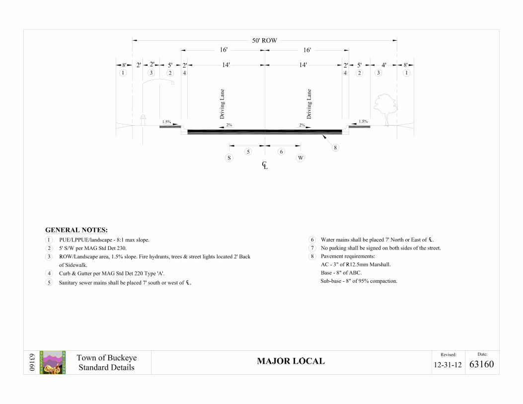
6-3.107 Major Local: A. Provides for traffic movement between collector streets and local streets.
B. Center turn lanes may be required.

Section 6-3 STREET PLANNING AND DESIGN CRITERIA
Town of Buckeye December 2012 Page 11
C. No driveway access is allowed.
D. Provides one (1) travel lane in each direction.
E. Have pedestrian, bicycle, and lighting requirements.
6-3.108 Local: A. Provide direct access to abutting land uses, provide access to the collector street system and
accommodate low traffic volumes.
B. Designed to discourage high travel speeds.
C. Are not intended for through traffic.
D. Provides one (1) travel lane in each direction.
E. Have pedestrian, bicycle, and lighting requirements.
6-3.109 Commercial Collector A. Shall be used in all commercial, business, industrial and other areas that are not residential.
B. Provides one (1) travel lane in each direction.
C. Center turn lanes are required.
D. All connections require right hand decel / turn lanes.
E. Have pedestrian, bicycle, and lighting requirements.
6-3.110 Residential Entrance A. Street section used to connect local streets to Collectors or Arterials.
B. Maximum length 130 feet.
C. No driveway access is allowed.
D. Provides one (1) travel lane in each direction.
E. Have pedestrian, bicycle, and lighting requirements.
6-3.200 Street Design Criteria:
6-3.201 Cross Sections: A. For the Town standard street cross sections see TOB Details in Appendix 1.
6-3.202 Lane Widths: A. Refer to all Town standard street cross sections for standard lane widths. The standard lane width
to be used for all lanes is 12 feet, which does not include gutter pan, 1.5 feet of “shy” distance or other shoulder type items.
B. If severe constraints make it near impossible to provide the standard lane width, then the “minimum” value of 11 feet for through lanes and 10 feet for turn lanes may be used with prior approval from the Town Engineer.

Section 6-3 STREET PLANNING AND DESIGN CRITERIA
Town of Buckeye December 2012 Page 12
C. Parking lanes shall be a minimum of 8 feet and maximum of 10 feet, not including the 1.5 foot of gutter pan.
6-3.203 Street ROW: A. ROW requirements are based on the space needed for the ultimate street cross section.
B. ROW provides for adequate lanes, drainage facilities, trails, sidewalks, cut or fill slopes, bicycle paths/lanes, traffic control devices, water, sewer, signage, other Town utility appurtenances and other public facilities as approved by the Town.
C. ROW may be required in addition to the standard ROW section in certain cases:
1. Cut or fill slopes cannot be confined within the standard ROW width.
2. The sight distance line for horizontal curves or intersections do not stay within the ROW.
3. Auxiliary lanes are required, e.g., right-turn lanes, bus bays, acceleration lanes, or dual left-turn lanes.
D. ROW “clips” are required at all intersections. Curvilinear ROW at intersections is not allowed. See Table 2 for ROW clip dimensions per street classifications.
E. A minimum of 5 feet additional ROW is required at all right hand turn bays.
F. All ROW transitions shall be made at 90 degree angles and shall be widened at the starting location of the reason causing the widening. The ROW shall be widened to the full width requirement; stepping or tapering is not allowed.
G. In areas that are master planned with narrower or smaller ROW than required by the design standards set forth in this section, the development will try and comply with the design standards whenever possible; provided, however, that the development shall always comply with the street sections and widths.
6-3.204 Public Utility Easements (PUE): A. PUEs are required along the outside of all public and private streets and shall parallel all aspects
of the ROW.
B. All locations that have overhead power line relocation require a minimum of a 10 foot PUE.
C. All locations without overhead power lines require an 8 foot PUE.
D. LPPUE shall be used in areas where the Town does not service water or sewer utilities.
6-3.205 Pavement Cross-Section Slopes: A. Typical Street Cross Sections:
1. Undivided streets shall have a normal crown that has a two-way cross-slope with the high point being at the street centerline.
2. Divided streets should have a cross-slope on each pavement section. The two pavement section should be designed as if they are not a divided section and mirror each other by design. The high point of each pavement section shall be located on the interior edge of pavement nearest to the median, except when there is superelevation.
Section6-3 STREET PLANNING AND DESIGN CRITERIA
Town of Buckeye December 2012 Page 13
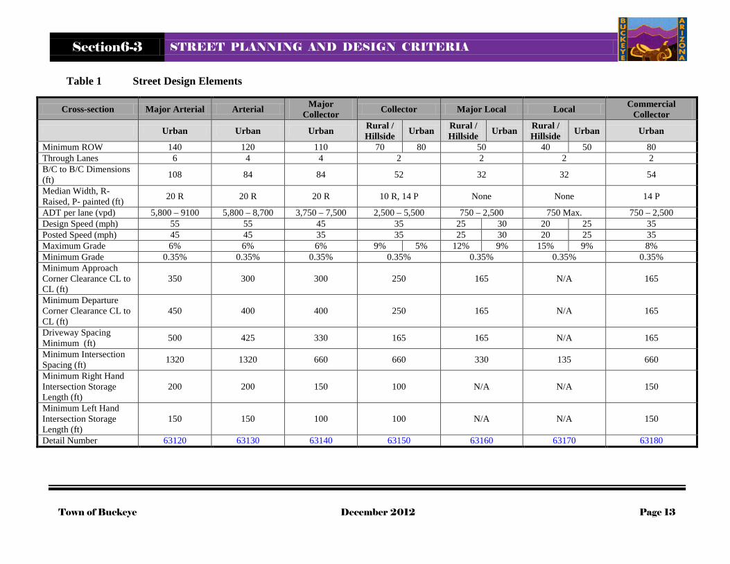
Table 1 Street Design Elements
Cross-section Major Arterial Arterial Major Collector Collector Major Local Local Commercial
Collector
Urban Urban Urban Rural / Hillside Urban Rural /
Hillside Urban Rural / Hillside Urban Urban
Minimum ROW 140 120 110 70 80 50 40 50 80 Through Lanes 6 4 4 2 2 2 2 B/C to B/C Dimensions (ft) 108 84 84 52 32 32 54
Median Width, R-Raised, P- painted (ft) 20 R 20 R 20 R 10 R, 14 P None None 14 P
ADT per lane (vpd) 5,800 – 9100 5,800 – 8,700 3,750 – 7,500 2,500 – 5,500 750 – 2,500 750 Max. 750 – 2,500 Design Speed (mph) 55 55 45 35 25 30 20 25 35 Posted Speed (mph) 45 45 35 35 25 30 20 25 35 Maximum Grade 6% 6% 6% 9% 5% 12% 9% 15% 9% 8% Minimum Grade 0.35% 0.35% 0.35% 0.35% 0.35% 0.35% 0.35% Minimum Approach Corner Clearance CL to CL (ft)
350 300 300 250 165 N/A 165
Minimum Departure Corner Clearance CL to CL (ft)
450 400 400 250 165 N/A 165
Driveway Spacing Minimum (ft) 500 425 330 165 165 N/A 165
Minimum Intersection Spacing (ft) 1320 1320 660 660 330 135 660
Minimum Right Hand Intersection Storage Length (ft)
200 200 150 100 N/A N/A 150
Minimum Left Hand Intersection Storage Length (ft)
150 150 100 100 N/A N/A 150
Detail Number 63120 63130 63140 63150 63160 63170 63180

Section 6-3 STREET PLANNING AND DESIGN CRITERIA Section 6-3 S
Town of Buckeye December 2012 Page 14
3. Unusual conditions may cause cross-slope to vary, but:
a. Design / desirable cross-slope is 2.0%
b. Maximum cross-slope is 3.0%
c. Minimum cross-slope is 1.0%
4. All deviation from the desirable cross-slope is subject to review and approval by the Town.
5. Cross slope shall be calculated to the lip of gutter (pavement only). To calculate the proper flow line elevation see Figure 1 to account for the proper dimension from the pavement surface at the lip of gutter to the flow line.
a. Example: cross slope = (centerline elevation – flow line elevation – lip to gutter dimension) / width of the asphalt. All dimensions in feet.
Figure 1 Dimension from Lip to Flow Line
B. Cross-Sections in Dip Sections:
1. A dip section is any section of street where water is designed to cross the centerline of the street.
2. Street dip sections shall be avoided.
3. All lots within new subdivisions shall be provided with a “dry” access from at least one direction. A “dry” access means no water flowing across the road in the 100 year 6/24 hour storm. This allows for safe and efficient emergency vehicle access.
4. Pavements through dip sections shall have a one way slope, (no crown).
5. Dip sections are only allowed on local streets, and not allowed on collector or arterial streets.
6. If a dip section is designed on a collector or arterial road it shall be for an interim period of time. An agreement with the Town is required to define when the dip section will be replaced as a dry crossing.

Section 6-3 STREET PLANNING AND DESIGN CRITERIA
Town of Buckeye December 2012 Page 15
7. Transitions back to normal street cross-slopes will be needed at both ends of the dip section.
8. Curbing and medians shall not be raised, and cut-off walls shall be installed.
9. Dip crossings shall be pursuant to MAG Detail 552.
6-3.206 Medians: A. Medians shall be provided on all parkways, arterials and collector streets, not minor collectors.
B. Median widths are measured from the back of median curb to back of median curb. Where there is no curb it is measured for the center of the edge of lane stripe or painted median stripes. Median widths shall be pursuant to Table 1.
C. Medians shall never be smaller than:
1. 12 feet for a painted median
2. 8 feet for a raised median
3. 4 feet for a raised median nose adjacent to a left-turn lane
4. A special circumstance may allow a raised median smaller than 4 feet if approved by the Town.
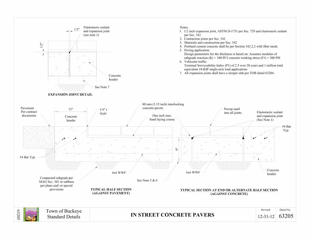
D. A median nose of 4 feet or less shall be paved with concrete pavers. The paved surface should have the same cross-slope as the street.
E. Medians that are 5 feet or more in width shall be landscaped. The grading in the median shall be pursuant to Figure 2.
1. Sloped to the center at a grade no less than 5%
2. Top of landscaping shall be no closer than 2 inches to the top of curb
3. A MAG 537 catch basin shall be placed in the center of the median when necessary.
Figure 2 Median Grading
4. All median landscaping and other features shall not be in conflict with any sight visibility triangles for traffic at intersections or driveways for through traffic or vehicles entering from the side. Refer to AASHTO and the Town’s sight distance criteria to verify if there are conflicts.
Section 6-3 STREET PLANNING AND DESIGN CRITERIA
Town of Buckeye December 2012 Page 16
F. Raised medians on collector and residential entrance public streets should be placed in a “tract” and shall be maintained by the Development’s HOA. All other medians shall be within the ROW but still maintained by the HOA.
G. All tracts that are within the ROW shall also have a roadway easement placed over them for Town Street and utility use.
H. Decorative rocks shall not be used in medians less than 4 feet in width.
I. Flush medians should be striped to provide a continuous left turn lane. The median shall be paved with asphalt or concrete, matching the grade of the adjacent street paving.
J. If a street has a raised median, it is not possible to provide an opening in the median for every street intersection or driveway location. Likewise, if a street currently does not have a raised median, but in the build out condition will have a raised median, the Town cannot allow interim turning movements that are not consistent with the ultimate build out of the street.
K. Median openings shall be as follows for arterial and major collector streets:
1. Median openings at 660 feet from a signalized or future signalized intersection shall be at most a ¾ access point, right in, right out and left in. No left turns out are allowed.
2. Median openings at 1,320 feet from a signalized or future signalized intersection shall be at most a full turning access point, right in, right out, left in and left out.
3. In order to allow median openings at these locations additional ROW and pavement width may be required.
4. Collector street median openings are determined by the amount of left turn storage required for each intersection.
5. All median openings shall be verified in a Town approved TIA.
L. In all locations where cross-slope, pavement warping or other design causes runoff to collect or run along a median curb, a storm drainage system shall be provided to collect the runoff along the median curb. In no case shall nuisance water from against the median curb be allowed to drain across adjacent lanes of pavement.
6-3.207 Curbs: A. All curbs shall be constructed pursuant to MAG standards unless modified by the Town.
B. Curb jointing shall match the adjacent sidewalk jointing when the sidewalk is attached to the curb.
C. Vertical Curbs:
1. Are required on all streets except Local Streets in single family residential neighborhoods.
2. Are required where there are detached sidewalks.
3. Shall be used adjacent to any open space, tract, side yard or other area that is not single family lot frontage.
4. Should be used when drainage considerations make it more desirable.
5. With gutter shall match the adjacent pavement cross-slope to the gutter slope direction.
6. Shall have a standard height of 6 inches except:

Section 6-3 STREET PLANNING AND DESIGN CRITERIA
Town of Buckeye December 2012 Page 17
a. Where fire lane or public maintenance vehicle access to abutting property must be provided over the curb, use mountable curb and gutter, per MAG Detail 220-2, Type E, F.
b. If special drainage requirements make a higher curb necessary, the height may be increased to 8 inches maximum and the width of the gutter may be increased to 24 inches.
c. Historical areas with variable curb dimensions.
7. Curb and gutter is required where water is being carried against the curb face.
D. Roll Curb:
1. 4 inch roll curb:
a. Is permitted on local single family residential streets except where vertical curb is required for drainage or open space.
b. Is not an acceptable substitute for curb ramps.
2. 6 inch roll curb:
a. Is discouraged for use in the Town, but where allowed, on a case by case basis, shall be used only on local single family residential streets.
b. The main characteristics on a 6 inch roll curb are that there is a 6 inch elevation difference from gutter pan flow line to top back of curb.
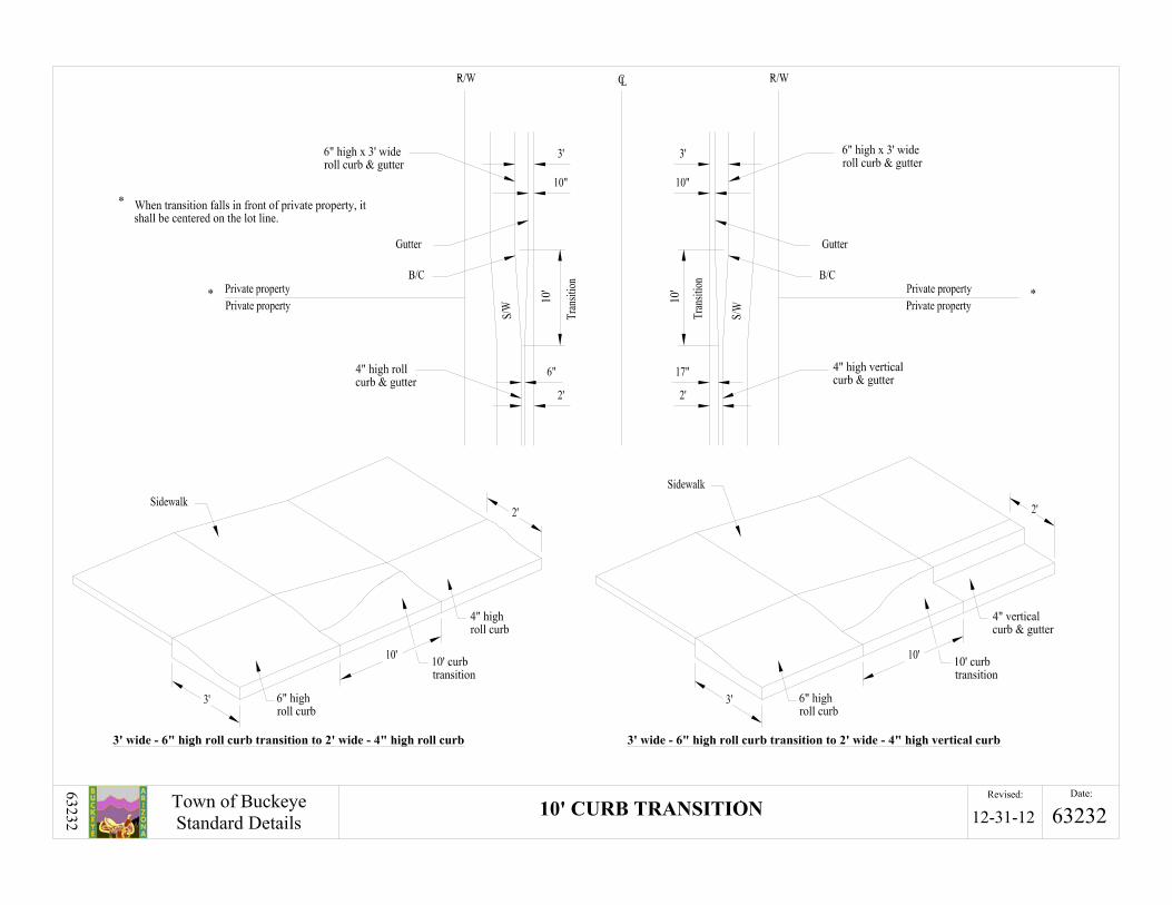
c. Requires a width of 3 feet to accommodate the transition for driveways See TOB Detail 63230 for specific details.
d. The 3 foot curb width poses additional design considerations that must be taken into account.
i. The lip of gutter shall match the typical street section and never project into the pavement.
ii. The extra foot of curb width must be taken up behind the back of curb in the sidewalk area, but the sidewalk width and locations does not change.
iii. Adjustments to street light, fire hydrants, etc. placement will be required.
e. Transitions to various curb types are shown in TOB Details in Appendix 1.
f. Is not an acceptable substitute for curb ramps.
E. Ribbon Curb:
1. Ribbon curb may be used in lieu of roll curb for local residential streets in low-density, large lot areas, typically where lot size is greater than 20,000 square feet.
2. If ribbon curb is used the sidewalk shall be located out of the clear zone for the street as per the AASHTO requirements.
3. When ribbon curb is used, drainage runoff from the road should not drain along the road but shall be directed to roadside drainage ditches if there is a common retention area, otherwise the runoff shall be directed into and retained on each lot.
F. Single Curb:
1. Single curb is only used on raised medians in the center of the street.
Section 6-3 STREET PLANNING AND DESIGN CRITERIA
Town of Buckeye December 2012 Page 18
2. Cannot be used when drainage is directed to or along the face of curb.
3. Per MAG Detail 222, type A.
G. Maricopa Edge:
1. Shall be used on all pavement when no form of curb is used.
2. Shall be used in conjunction with a minimum 10 foot shoulder and an adequate clear zone.
3. Per MAG Detail 201, type A.
H. Cut-Off Walls:
1. Are required in locations where drainage is designed and permitted to flow across the street.
2. Shall conform to MAG Detail 552, modified to be topped with 24 inch ribbon curb, MAG Detail 220-1, type B
3. Shall have a top that is flush with the pavement surface.
4. The exposed portion of the cut-off wall shall have the appearance of a ribbon curb, with the same width as the street’s regular curb and gutter.
5. Shall extend across the flow path in the dip section to protect the pavement structure during runoff flows from the 100 year storm.
6. Transitions will be needed between the regular curbs and the cut-off walls at each end of the dip section.
7. Rip rap or other types of erosion protection is required downstream of all cut-off walls.
6-3.208 Curb Returns: A. Vertical curb shall be used through the curb return from P.C. to P.T. regardless of whether the
tangent curb sections are vertical, or roll curb.
B. A MAG Detail 221 transition will be required as necessary between curb types.
C. All curb returns shall be provided with curb ramps with sidewalk from P.C. to P.T. per the applicable MAG sidewalk ramp detail as required by the ADA, unless sidewalk is not planned for the area. A corresponding ramp is always required on the opposite side of the street at local street intersections.
D. 4 inch vertical curb is allowed on local streets with ribbon and roll curb.
E. 6 inch vertical curb is required on all industrial, collector and arterial streets.
F. The radii for curb returns measured to the back of curb.
G. If a traffic signal exists or is planned, the ramp and apron shall provide access to the pedestrian push button.
H. These standards apply to both public and private streets.
I. The maximum longitudinal slope of a curb return, from P.C. to P.T. is 2.0%. Minimum curb return slope shall be 0.35% whenever the flow line is at the curb face.
6-3.209 Curb Ramps:

Section 6-3 STREET PLANNING AND DESIGN CRITERIA
Town of Buckeye December 2012 Page 19
A. All streets shall have ADA compliant curb ramps at all street intersections and all commercial driveways.
Table 2 Minimum Curb Return Radii and ROW Clip
MINIMUM CURB RETURN RADII AND ROW CLIP2
Street Classification
Residential Commercial / Industrial1 Curb Return
Radii (ft) ROW Clip Curb Return Radii (ft) ROW Clip
Major Arterial To:
Major Arterial 40 45 45 50 Arterial 40 45 45 50
Major Collector 35 40 40 45 Collector 35 40 40 45
Major Local 30 35 N/A3 N/A3 Local 30 35 35 40
Commercial Collector N/A3 N/A3 40 45 Residential Entrance 30 35 N/A3 N/A3
Commercial Driveway N/A3 N/A3 35 40
Arterial To:
Arterial 35 45 40 50 Major Collector 35 40 40 45
Collector 35 40 40 45 Major Local 30 35 N/A3 N/A3
Local 30 35 35 40 Commercial Collector N/A3 N/A3 40 45 Residential Entrance 30 35 N/A3 N/A3
Commercial Driveway N/A3 N/A3 35 40
Major Collector
To:
Major Collector 35 40 40 45 Collector 35 40 40 45
Major Local 30 35 N/A3 N/A3 Local 30 35 35 40
Commercial Collector N/A3 N/A3 40 45 Residential Entrance 30 35 N/A3 N/A3
Commercial Driveway N/A3 N/A3 30 35
Collector To:
Collector 35 40 N/A3 N/A3 Major Local 30 30 N/A3 N/A3
Local 25 30 N/A3 N/A3 Commercial Collector N/A3 N/A3 N/A3 N/A3 Residential Entrance 30 30 N/A3 N/A3
Commercial Driveway N/A3 N/A3 N/A3 N/A3 Private 25 25 N/A3 N/A3
Major Local To:
Major Local 25 25 N/A3 N/A3 Local 25 25 N/A3 N/A3
Private 25 25 N/A3 N/A3
Local To: Local 25 25 30 30 Private 25 25 30 30
Commercial Collector
To:
Commercial Collector N/A3 N/A3 35 40 Local N/A3 N/A3 30 35
Commercial Driveway N/A3 N/A3 30 30 Private N/A3 N/A3 30 30
1. To be used when adjacent zoning is other than residential, one corner dictates the entire intersection. 2. All dimensions are minimum, TIA may require larger due to traffic loadings 3. N/A refers to scenarios the Town does not anticipate.

Section 6-3 STREET PLANNING AND DESIGN CRITERIA
Town of Buckeye December 2012 Page 20
A. All local street intersections including all knuckles and “T” intersections require ADA compliant ramps. All locations on local streets require ramps on both sides of the street. “T” intersections require only one ramp opposite the intersecting street.
B. The only exception for the ramp provision is when sidewalk is not required in industrial areas that do not have pedestrian traffic.
C. Curb ramps at intersections without painted crosswalks, i.e. local streets shall be MAG Detail 235-2.
D. Curb ramps at a stop controlled intersection with painted crosswalks shall be the directional ramps per the TOB Detail 63240.
E. Mid-block ramps for 4 inch curb shall be per TOB Detail 63250.
F. Where needed on local streets where a driveway is conflicting with a ramp location a combination driveway-ADA ramp shall be used, per TOB Detail 63440.
G. Sidewalk transitions from attached to detached or vice versa are per TOB Detail 63238.
6-3.210 Design Speed: A. The design speed is the maximum speed for the safe operation of a vehicle.
B. Design speed is a selected speed used to determine the various geometric design features of the street.
C. The assumed design speed should be a logical one with respect to the topography, anticipated operating speed, the adjacent land use, and the functional classification of the street.
D. Local streets are typically exceptions because speed controls are typically included intentionally.
E. Every effort should be made to use as high a design speed as practical to attain a desired degree of safety, mobility, and efficiency within the constraints of environmental quality, economics, aesthetics, and social or political impacts.
6-3.211 Super-elevation in Curves: A. The Town discourages the use of superelevation unless absolutely necessary. Superelevation is
used to maintain riding comfort and to allow minimum radii on horizontal curves to be met where there are physical constraints that do not allow the larger normal crown street radii to be used. All superelevation shall be submitted to the Town Engineer for approval prior to the completion of the design drawings.
B. Super-elevation may only be used when other means of design will not work.
C. The following criteria shall be followed:
1. Superelevation 0.02 ft/ft (2%):
a. Superelevation of 0.02 ft/ft may be used when the standard non-superelevated geometrics cannot be provided due to circumstances beyond the control of the engineer and the general alignment cannot be changed.
2. Superelevation Greater than 0.02 ft/ft (2%):
a. Superelevation greater than 0.02 ft/ft may not be used except when approved by the Town Engineer. In no case shall a superelevation exceed 0.06 ft/ft.

Section 6-3 STREET PLANNING AND DESIGN CRITERIA
Town of Buckeye December 2012 Page 21
3. Transition for Superelevation:
a. The length of superelevation transition shall be based on the superelevation rate and the width of rotation. The axis of rotation shall generally be about the pavement centerline. All designs shall be per the AASHTO publication, A Policy on Geometric Design of Highways and Streets.
b. With respect to the beginning or ending of a horizontal curve, one-third (1/3) of the transition should be on the curve and two-thirds (2/3) of the transition should be on the tangent pavement section.
4. Drainage on Superelevated Curves:
a. Whenever superelevation is allowed on a divided street, a storm drainage system to collect the runoff along the median curb shall be provided. In no case shall nuisance water from the higher traveled way be allowed to cross the lower traveled way.
6-3.212 Horizontal Curves: A. Horizontal alignments should provide for efficient and comfortable operation of motor vehicles
at a uniform design speed for substantial lengths of street.
B. A horizontal curve is required when the angle of change in horizontal alignment is equal to or greater than one degree on arterial and collector streets.
C. The nature of the surrounding development, topography, and the street classification will establish the factors that determine the radius of a curve.
6-3.213 Minimum Radii of Curvature: A. The minimum radius of curvature will be determined by the design speed or by the stopping sight
distance.
B. Minimum Radii Based on Design Speed:
1. Table 5 and Table 6 contains the minimum radius of curvature for each street classification with and without a superelevation rate of 0.02 ft./ft.
2. Wherever possible, the radii used in design needs to be as large as possible.
3. If stopping sight distance conditions require a larger radius than that shown Table 5 and Table 6, then that larger radius becomes the minimum radius for the curve.
6-3.214 Consideration of Stopping Sight Distance: A. When walls, buildings, bridge piers, cut slopes, vegetation, or other obstructions are near the
street on the inside of a curve, they can block a driver's view of the road ahead. If they are too close, the driver will not have sufficient distance along the curved street to stop when an approaching vehicle or other object on the street comes into view.
B. For design, the driver’s eye is 3.5 feet above the center of the inside lane (the driving lane closest to the inside of the curve) and that the object in the street is 0.5 feet high in the center of the inside lane. The clear distance, “M,” is measured from the center of the inside lane to the view obstruction, see Figure 3, and per the current AASHTO standards.
C. For a quick check use 13 times the design speed, for exact distance, refer to the AASHTO Standards.

Section 6-3 STREET PLANNING AND DESIGN CRITERIA
Town of Buckeye December 2012 Page 22
6-3.215 Reduced Design Speeds on Curves: A. The reduction of a street design speed on a curve should be avoided; however, where physical
restrictions prohibit increasing the radius of the curve or the clear distance, “M” the design speed for the curved section may be reduced.
B. If this situation arises each case shall be presented including the hardship reasons to the Town Engineer. A review and approval is required by the Town Engineer prior to allowing a reduction to the design speed.
C. Appropriate signage in accordance with the MUTCD is required.
D.
Figure 3 View Obstructions and Horizontal Curves
E. The difference between the design speed for the street approaching the curve and the design
speed for the curve cannot be greater than 10 miles per hour.
F. The design speed for a curved street section shall not be reduced if the reduction occurs at the end of a long tangent or at any location where high approach speeds may be expected.
6-3.216 Compound Curves: A. Compound curves should be avoided whenever possible; however, if site conditions make the use
of compound curves unavoidable, the shorter radius needs to be at least 2/3 the length of the longer radius.
B. Compound curves are not permitted when design speeds require the shorter radius to be greater than 1,000 feet.
Section 6-3 STREET PLANNING AND DESIGN CRITERIA
Town of Buckeye December 2012 Page 23
6-3.217 Tangent Sections between Curves in the Same Direction: A. On two-lane roads, tangent sections are needed between two curves in the same direction. If the
pavement cross-sections through the curves do not have superelevation then the minimum lengths shall be Table 5 and Table 6.
B. If superelevation is provided in the curved portions of the street, then the tangent lengths will be determined by the superelevation transition lengths indicated in AASHTO.
6-3.218 Tangent Sections between Reverse Curves: A. A tangent section must be provided between two curves that curve in the opposite direction.
Minimum lengths for tangent sections between reverse curves without superelevation are provided in Table 5 and Table 6.
B. If the curve radii are at least 50% greater than the radii required by the design speed, a tangent section may not be required depending on grades, topography and vegetation.
C. If superelevation is provided for the curves, then the superelevation transition lengths indicated will determine the minimum length of tangent sections between reverse curves.
6-3.219 Tangent Sections Approaching Intersections: A. A tangent section shall be provided between a street intersection and a curve unless otherwise
approved by the Town.
B. The minimum tangent length is shown in Table 5 and Table 6, and shall be measured from the end of the curve to the edge or curb line of the intersecting street.
6-3.220 Longitudinal Street Grades: A. Refer to Table 5 for maximum allowable longitudinal street grades.
B. The minimum longitudinal street grade for all streets is 0.35%.
C. Wherever possible, longitudinal street grades greater than or equal to the minimum grade are to be provided.
D. Where necessary, grades less than 0.35% may be used with approval from the Town.
E. Grades that exceed the maximum longitudinal grades allowed, may be used with approval from the Town Engineer, and Fire Department.
6-3.221 Vertical Curves: A. Vertical-curves shall be designed to provide adequate sight distance, safety, comfortable driving,
good drainage, and a pleasant appearance.
B. Algebraic difference in grades without a vertical curve on continuous streets shall be equal to or less than the values specified for the following design speeds including:
1. 0.2% Federal Aid Projects
2. 0.3% Equal to or greater than 55 mph
3. 0.5% Equal to or greater than, 40 mph, but less than 55 mph
4. 1.0% Less than 40 mph
Section 6-3 STREET PLANNING AND DESIGN CRITERIA
Town of Buckeye December 2012 Page 24
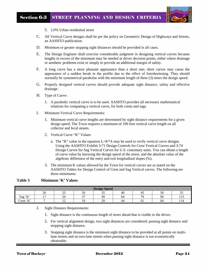
5. 2.0% Urban residential street
C. All Vertical Curve designs shall be per the policy on Geometric Design of Highways and Streets, an AASHTO publication.
D. Minimum or greater stopping sight distances should be provided in all cases.
E. The Design Engineer shall exercise considerable judgment in designing vertical curves because lengths in excess of the minimum may be needed at driver decision points, either where drainage or aesthetic problems exist or simply to provide an additional margin of safety.
F. A long curve has a more pleasant appearance than a short one; short curves may cause the appearance of a sudden break in the profile due to the effect of foreshortening. They should normally be symmetrical parabolas with the minimum length of three (3) times the design speed.
G. Properly designed vertical curves should provide adequate sight distance, safety and effective drainage.
H. Type of Curve:
1. A parabolic vertical curve is to be used. AASHTO provides all necessary mathematical relations for computing a vertical curve, for both crests and sags.
I. Minimum Vertical Curve Requirements:
1. Minimum vertical curve lengths are determined by sight distance requirements for a given design speed. The Town requires a minimum of 100 foot vertical curve length on all collector and local streets.
2. Vertical Curve “K” Values
a. The “K” value in the equation L=K*A may be used to verify vertical curve designs. Using the AASHTO Exhibit 3-71 Design Controls for Crest Vertical Curves and 3-74 Design Curves for Sag Vertical Curves for U.S. customary units. You can obtain a length of curve value by knowing the design speed of the street, and the absolute value of the algebraic difference of the entry and exit longitudinal slopes (%).
3. The minimum K values allowed by the Town for vertical curves are as stated on the AASHTO Tables for Design Control of Crest and Sag Vertical curves. The following are those minimums:
Table 3 Minimum ‘K’ Values
Design Speed 20 25 30 35 40 45 50 55
Sag ‘K’ 17 26 37 49 64 79 96 115 Crest ‘K’ 7 12 19 29 44 61 84 114
J. Sight Distance Requirements:
1. Sight distance is the continuous length of street ahead that is visible to the driver.
2. For vertical alignment design, two sight distances are considered: passing sight distance and stopping sight distance.
3. Stopping sight distance is the minimum sight distance to be provided at all points on multi-lane streets and on two-lane streets when passing sight distance is not economically obtainable.

Section 6-3 STREET PLANNING AND DESIGN CRITERIA
Town of Buckeye December 2012 Page 25
4. Stopping sight distance shall also be provided in the vicinity of intersections.
5. Table 7 lists the minimum passing and stopping sight distances for the various street classifications at various design speeds, for passenger cars only.
6. Stopping Sight Distance:
a. The minimum stopping sight distance is the distance required by the driver of a vehicle, traveling at a given speed, to bring the vehicle to a stop after an object on the road becomes visible. Stopping sight distance is measured from the driver's eyes, 3.5 feet above the pavement surface, to an object 0.5 feet high on the street, or currently accepted AASHTO standards.
7. Passing Sight Distance:
a. Passing sight is the minimum sight distance that must be available to enable the driver of one vehicle to pass another vehicle safely, without interfering with the speed of an oncoming vehicle. The sight distance available for passing at any one place is the distance at which a driver, whose eyes are 3.5 feet above the street surface, can see the top 0.8 feet of an object 4.35 feet high on the road (corresponding to an object height of 3.5 feet high), or pursuant to currently accepted AASHTO standards.
8. Minimum Crest Vertical Curve Lengths:
a. Minimum vertical curve lengths are determined by sight distance requirements for a given design speed.
b. Crest Vertical Curve Lengths:
i. Minimum crest curve lengths are determined by either the stopping sight distance or the passing sight distance, whichever provides the greatest curve length.
ii. The minimum crest vertical curve lengths on streets with two or more through travel lanes per direction must only meet stopping sight distance requirements.
c. Minimum Crest Vertical Curve Length Determined by Stopping Sight Distance:
i. The following equations are to be used to determine the minimum crest vertical curve lengths based upon stopping distance requirements, or pursuant to currently accepted AASHTO standards:
6-3.222 Combined Horizontal and Vertical Curves: A. When horizontal and vertical curves are combined, the horizontal curve shall lead and follow the
vertical curve, and not be introduced near the top or bottom of a crest vertical curve or bottom of a sag vertical curve. For additional information on this topic, see the AASHTO’s Policy on Geometric Design of Highways and Streets.

Section 6-3 STREET PLANNING AND DESIGN CRITERIA
Town of Buckeye December 2012 Page 26
Figure 4 Minimum Crest Vertical Curve Length Determined by Stopping Sight Distance
When Ss < L, L = �ASs 2�
2158
When Ss > L, L = (2Ss) - 2158𝐴
L = Length of curve in feet.
Ss = Stopping sight distance in feet for a given design speed.
A = Algebraic grade difference in percent.
a. Minimum Crest Vertical Curve Length Determined by Passing Sight Distance
i. The following equations are to be used to determine the minimum crest vertical curve lengths based upon sight distance requirements:
Figure 5 Minimum Crest Vertical Curve Length Determined by Passing Sight Distance
When Sp < L, L = �ASp 2�
2800
When Sp > L, L = (2Sp) - 2800𝐴
Sp = Passing sight distance in feet for a given design speed. L = Length of curve in feet.
A = Algebraic grade difference in percent.
2. Sag Vertical Curve Lengths
a. Minimum sag vertical curve lengths are determined by either the stopping sight distance or comfort factors. The longer of the two possible minimum curve lengths shall be used.
b. Minimum Sag Vertical Curve Length Determined by Stopping Sight Distance
i. The following equations are to be used to determine the minimum sag vertical curve length based upon stopping sight distance requirements:

Section 6-3 STREET PLANNING AND DESIGN CRITERIA
Town of Buckeye December 2012 Page 27
Figure 6 Minimum Sag Vertical Curve Length Determined by Stopping Sight Distance
When Ss < L, L = �ASs 2�(400+3.5𝑆𝑠)
When Ss > L, L = (2Ss) – �(400+3.5𝑆𝑠)𝐴
�
Ss = Stopping sight distance in feet for a given design speed.
L = Length of curve in feet.
A = Algebraic grade difference in percent.
c. Minimum Sag Vertical Curve Length Determined by Comfort Factors
i. The following equation is to be used to determine the minimum sag vertical curve length based upon comfort factors:
Figure 7 Minimum Sag Vertical Curve Length Determined by Comfort Factors
L = �AV2�
46.5
L = Curve length in feet.
A = Algebraic grade difference in percent.
V = Design speed in miles per hour.
6-3.300 Intersections:
6-3.301 General Intersection Criteria: A. Although all intersections share certain common elements, they are not subject to generalized
treatment. To minimize conflicts and provide for anticipated traffic movements each intersection shall be evaluated with regard to its individual characteristics and designed based on the following factors:
1. Traffic factors such as capacities, turning movements, vehicle size and operating characteristics, vehicle speed, pedestrian and bicycle movements, transit operations, and accident history.
2. Physical factors such as topography, existing conditions, channelization requirements; and available sight distance.
3. Human factors such as driving habits, reaction to surprises, decision and reaction time, and natural paths of movement.
6-3.302 Intersection Spacing: A. Intersections along major streets shall be kept to a minimum.

Section 6-3 STREET PLANNING AND DESIGN CRITERIA
Town of Buckeye December 2012 Page 28
B. See Table 1 for intersection spacing for all street types.
C. New intersections on major streets shall be located to align with planned median openings.
D. New intersections on minor streets shall be located to avoid creating conflicting turning movements with existing intersections or driveways.
6-3.303 Angle of Intersection: A. A right-angle intersection provides the shortest crossing distance for intersecting traffic streams.
It also provides the most favorable condition for drivers to judge the relative position and speed of intersecting vehicles.
B. Where special conditions exist, intersection angles may diverge from a right-angle:
1. On arterials and collectors by a maximum of 2 degrees (up to 4 degrees with approval of the Town Engineer).
2. On minor collectors and local by a maximum of 4 degrees (up to 15 degrees with approval of the Town Engineer).
6-3.304 Alignment and Profile: A. Intersections occurring on horizontal or crest vertical curves are undesirable and shall be avoided.
When there is latitude in the selection of intersection locations, vertical or horizontal curvature should be avoided.
B. An alignment or grade change is frequently warranted when major intersections are involved. If a curve is unavoidable, it should be as flat as site conditions permit. Where the grade of the through street is steep, flattening through the intersection is desirable as a safety and efficiency measure.
C. For all intersections, all ADA requirements shall be met.
D. The intersecting streets’ profiles and cross slopes need to be coordinated with one another to ensure a safe and comfortable driving surface. Typically this may mean extending grades through the intersection for approximately 75 feet to 150 feet. Short vertical curves may be necessary in lieu of grade breaks.
6-3.305 Intersection Cross Slopes A. Major Arterial, Arterial, and Major Collector intersections shall be designed so that lower
classification roadways do not affect the mainline profile or cross slope through the intersection.
B. Where two major streets meet the design shall accommodate flattening the crown of the roads to minimize the “bump” created from the crown of the road at the centerline.
C. All signalized intersections shall be designed to incorporate the flattening of the crown as much as possible.
D. See TOB Detail 63340 for an example.
6-3.306 Intersection and Driveway Sight Distance: A. In order to provide the opportunity for vehicles at an intersection to safely cross or make left or
right turns onto a through street, adequate sight distance shall be provided.

Section 6-3 STREET PLANNING AND DESIGN CRITERIA
Town of Buckeye December 2012 Page 29
B. Intersection sight distance applies to all stop controlled side streets, all approaches to signalized intersections, all commercial driveways, and other intersections as determined by the Town.
C. Sight distance shall also be provided for left turning traffic turning from the main street as described in AASHTO Intersection Sight Distance Case F. If opposing left turn lanes are present, the opposing left turns shall be off-set in a positive way to allow for sight distance when opposing vehicles are present.
D. Sight distance should be based on the design speed for the street. Design speeds for new streets should conform to those as specified in this design manual.
E. Design speeds are 10 mph higher than the anticipated posted speed limit.
F. All sight distance lines shall be contained within Town ROW by a minimum of 2 feet.
G. Internal driveway intersections on private property are excluded from these requirements.
H. The sight distance requirements outlined below are required for all private and public street intersections and at all intersections of driveways onto public or private streets.
1. Figure 8 depicts the technique used to determine the driver’s eye location and an approaching vehicle; a line is then drawn to connect these 2 points.
2. Continuous unobstructed line of sight shall be provided along this line and throughout the approach to the intersection, providing an unobstructed sight triangle to the side street driver.
3. Sight lines are to be drawn on street and landscaping plans to represent the areas that shall be free of all objects and topography in excess of 24 inches above the street surface, however, certain vegetation will be allowed.
4. Vegetation placed within the sight distance line will be of a low variety that remains below 24 inches when mature.
5. No trees of any kind are allowed within the sight distance line.
I. Right-Angle Intersections:
1. Right-angle intersections are those whose legs meet at an angle of 88 to 90 degrees. For these right-angle intersections the sight distances shown in Table 5 and Table 6 are to be used with Figure 8 to calculate the sight triangle. Table 5 and Table 6 present the intersection sight distances for all street classifications which were determined assuming passenger car traffic.
2. Table 7 presents the sight distance requirements for varying street widths and design speeds for passenger cars, single unit trucks and combination trucks. If high volumes of truck traffic are anticipated, sight distances given in Table 7 are used.
3. Sight distances for vehicles turning left from the main street should also be considered and calculated based on the AASHTO Geometric Design of Highways and Streets.
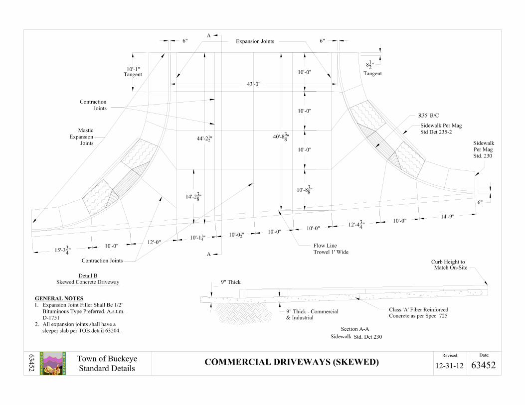
J. Skewed Intersections:
1. For skewed intersections where the intersection angles are less than 88 degrees, sight distances shall be calculated in accordance with the procedures described in AASHTO’s Geometric Design of Highways and Streets.
2. Skewed intersection design shall include appropriate design for pedestrian crossings and the location of curb ramps.

Section 6-3 STREET PLANNING AND DESIGN CRITERIA
Town of Buckeye December 2012 Page 30
Figure 8 Intersection/Driveway Sight Distance Requirements
K. Intersections Within or Near a Curve:
1. Sight distance measurements, identified as S in Figure 8, need to follow the curved street alignment when the intersection is within or near a horizontal curve.
6-3.307 Sight Visibility Triangles (SVT): A. SVTs should be used as a means to limit the height of structures, vegetation and other
improvements on corner properties immediately adjacent to intersections.
B. SVTs are not to be used as a substitute for intersection sight distance!
C. SVTs provide additional visibility around corners for all intersection approaches and should be applied to the design of perimeter walls and landscape features.
D. Items within the SVT cannot be higher than 24” measured from the street surface.
E. Figure 9 depicts the method used to determine the SVT.
F. All SVTs shall be calculated from the intersecting ROW lines.
G. The SVT requirements contained in both Figure 8 and Figure 9 are applied at all corner lots.
H. All SVTs shall be dedicated as easements on al final plats or maps of dedication.
I. The dimension “X” in Figure 9 is as follows:
1. Local streets that intersect and the centerline deviates from 90° by 0° to 10°, X = 33feet.
2. Local street that intersect at and the centerline deviates from 90° by 10° to max 15°, X = 40 feet.
1. 6 feet measured to nearest lane line or centerline. 2. 15 feet measured from face-of-curb or edge-of-travelway. 3. Intersection/Driveway Sight Distance Requirements 4. 24” Object Height Limit (Measured from Street Surface). S. Intersection sight distance in feet.
S
S

Section 6-3 STREET PLANNING AND DESIGN CRITERIA
Town of Buckeye December 2012 Page 31
3. All other intersections, X = 33 feet.
J. Building envelopes shall not be located in the SVT
Figure 9 Sight Visibility Triangles
6-3.308 Intersections with an Unpaved Leg: A. If an intersection has a leg that is unpaved, the paving to be placed in the intersection shall
extend, at a minimum, to the end of the normal curb return location on the unpaved leg.
6-3.309 Valley Gutters at Street Intersections: A. Locations of Valley Gutters:
1. Valley gutters may only be used across local residential streets. Exceptions can be made on existing streets to eliminate drainage issues but such exceptions shall be subject to the approval of the Town Engineer.
B. Valley Gutter Widths:
1. Valley gutters shall be a minimum of 6 feet but 7, 8 and 10 foot wide valley gutters are allowed.
C. All valley gutters and associated aprons are per MAG Detail 240, modified to incorporate fiber mesh.
D. Mid-block valley gutters are discouraged but may be allowed where drainage capacity or efficient removal of drainage from the street can be done effectively, subject to the prior approval of the Town Engineer.
E. Minimum valley gutter slope is 0.35%.
F. Pavement crown warps to accommodate the valley gutters shall be a minimum of 50 feet in length measured along the centerline of the street.

Section 6-3 STREET PLANNING AND DESIGN CRITERIA
Town of Buckeye December 2012 Page 32
6-3.310 Auxiliary Lanes: A. An exclusive turning lane permits separation of conflicting traffic movements and removes
turning vehicles from the flow of through traffic.
B. These standards apply for right and left-turn lanes at street intersections and for deceleration lanes at mid-block driveways.
C. The requirement for an auxiliary lane may necessitate additional ROW.
D. Modifications to the storage and transition lengths may be allowed by the Town where the conditions do not allow the full design standard to be met.
1. Right-Turn Lanes:
a. Right-turn lanes are required at all street intersections on major arterials, arterials and major collectors. Right-turn lanes are required at all commercial and industrial driveways. Right-turn lanes may be required by the Town on collector street intersections.
b. The lane lengths should be determined based on the anticipated turning volume and whether there is signalized or un-signalized traffic control.
c. See Table 1 for the minimum storage lengths for right turn lanes.
2. Left-Turn Lanes:
a. Left-turn lanes are required at all arterial and collector street intersections and driveways.
b. Left-turn lanes may also be required at street intersections on major locals based on the projected left-turn volume and conflicting through volume.
c. The lane lengths should be determined based on the anticipated turning volume and whether there is signalized or un-signalized traffic control.
d. For left turn lanes at signalized intersections, dual turn lanes should be considered when the turn volume exceeds 200 vehicles per hour, the opposing through volume exceeds 1,000 vehicles per hour, or the delay to left turning vehicles exceeds 45 seconds.
e. Sight distance shall be considered and calculated for these movements based on the AASHTO Policy on Geometric Design for Highway and Streets to determine the allowance of permitted left turns.
f. See Table 1 for the minimum storage lengths for left-turn lanes.
6-3.311 Median Design: A. Configuration of Raised Median Openings:
1. If the street intersection legs intersect at an angle of 88 to 90 degrees, the configuration of the median opening will be determined by the information shown below on Figure 10 If the streets intersect at an angle less than 88 degrees, the median opening configuration will have to be determined to the satisfaction of the Town.
2. All other median openings will be designed on a case by case basis as directed by the Town Engineer.
B. Cross-Slope of Raised Median Openings:

Section 6-3 STREET PLANNING AND DESIGN CRITERIA
Town of Buckeye December 2012 Page 33
1. The cross-slope in the median opening is limited to 0.02 ft./ft. Median openings on curves with superelevation exceeding 0.02 feet/foot will not be permitted.
C. Flush Medians:
1. Flush, painted medians are required
a. On all streets without raised medians per Table 1.
b. Where raised medians are not required by the Town at the time of street construction.
c. Where raised medians are not practical at the time of street construction.
2. Median widths for these streets are listed in Table 1.
Figure 10 Median Opening for Intersentions
6-3.312 Traffic Control: A. Traffic control at all new intersections should initially be stop controlled on the minor street. Any
higher means of traffic control, 4-way stop, or a traffic signal will require approval by the Town based on an approved engineering study. Guidelines for 4-way stop and traffic signal controlled intersections are outlined below. Intersections of local residential streets within subdivisions are assumed to be stop controlled and will typically not need signage.
B. Four-Way Stop Controlled Intersections:
1. Four-way (or multi-way) stop controlled intersections are allowed only when based on a TIA approved by the Town based on the criteria contained in the MUTCD. Four-way stop control is generally utilized for the intersections of two similar classification streets where volumes are approximately equal or at intersections where there is a safety concern (such as limited sight distance).
C. Traffic Signal Controlled Intersections:
Cross Street / Driveway
a. B = A + 15; 40’ Minimum for all local and collector streets
b. B = A + 25; 40’ Minimum for all arterial streets
c. Notes: 1. This sketch is for a three leg intersection. If the intersection has four legs, the right side will also have an
auxiliary lane for left turns, and the median on the right will have the same configuration as the one on the left side rotated 180°
2. See Table 1 for median dimensions.
Beg. / End of median (not at intersections)

Section 6-3 STREET PLANNING AND DESIGN CRITERIA
Town of Buckeye December 2012 Page 34
1. Traffic Signal Warrants:
a. New traffic signal controlled intersections are allowed only when based on a TIA approved by the Town using MUTCD criteria.
b. Traffic signal warrants are generally based on existing traffic volumes not projected traffic volumes.
2. Contributions for future traffic signal construction are required for all developments Payment toward future construction should not be interpreted to mean a traffic signal is warranted.
3. New intersections or modifications to existing intersections where the Town anticipates a possible future traffic signal shall have traffic signal conduit and pull boxes installed.
a. Traffic signal conduits to be installed are three -3 inch SCH 80 conduits to “box” the intersection. These are to be installed under the pavement being constructed or modified but extended to the ultimate pull box location.
b. ADOT number 7 pull boxes are required at all corners and in the median if necessary.
c. The layout will be coordinated with the Town.
4. All major arterial and arterial streets require the installation of traffic signal interconnect conduit included with the half street improvements.
a. These conduits shall be two-3 inch SCH 80 conduits pursuant to Town requirements.
5. Traffic Signal Spacing:
a. Traffic signals should be spaced no closer than ½ mile on major arterials and minor arterials, with 1 mile spacing desirable.
b. Traffic signals should be spaced no closer than ¼ mile on collector streets, with ½ mile spacing desirable.
c. Closer spacing will interfere with traffic progression and signal coordination. Any deviation from these standards requires approval from the Town Engineer based on an approved study that indicates no significant deterioration in traffic progression.
6-3.400 Street Access and Driveways:
6-3.401 Driveway Spacing: A. Minimum driveway spacing will generally conform to the following standards. This minimum
spacing applies to proposed site driveway separation as well as separation from existing or planned driveways on adjacent parcels.
B. See Table 1 for minimum driveway spacing.
C. For sites that have frontage on two streets, primary access shall be onto the minor street frontage.
D. A maximum of two (2) driveway openings is permitted to a particular site or parcel from the abutting street(s).
E. The Town may permit additional driveway entrances when projected travel demands indicate it is in the interests of good traffic operation, and when adequate street frontage exists to maintain the above guidelines.

Section 6-3 STREET PLANNING AND DESIGN CRITERIA
Town of Buckeye December 2012 Page 35
F. Where new development adjoins other similarly zoned property or compatible land uses, a cross access easement may be required to permit vehicular movement between the parcels and reduce the number of access points required onto the adjacent public street. This may be required regardless of the development status of the adjoining property, unless the cross access is determined to be unfeasible by Town staff.
6-3.402 Driveway Location Limitations: A. A new access driveway will not be allowed (measured to the driveway centerline):
1. Within 30 feet of any commercial property line, except when it is a joint-use driveway serving two abutting commercial properties and access agreements have been exchanged between, and recorded by, the two abutting property owners;
2. When the total width of all driveways serving a property exceeds 50% of the curb line frontage;
3. See all corner clearances in Table 1 for the location of driveways to intersections.
a. Corner clearance is measured from the centerline of the street to the centerline of the driveway.
4. When adequate sight distance cannot be provided to vehicles on the driveway attempting to access the street, see Figure 9 and Table 8.
B. All pedestrian access across driveways shall meet all ADA requirements including a maximum of a 2% cross slope.
C. The maximum grade brake in an alley or commercial driveway is 6%.
6-3.403 Protection of Access: A. For proper control of driveway access, a V.N.A.E. is to be granted to the Town, except at
approved access points, along all collector and arterial streets when abutting property develops.
B. The V.N.A.E. shall be a minimum of 1 foot wide and shall be shown on the final plat and paving plans.
C. On local streets except in the fronts of lots to allow residential access to the home. All side yards and rear yards adjacent to streets, tracts and open space shall have a V.N.A.E.
6-3.404 Residential Development Driveways: A. Single Family Residential Development:
1. Driveway entrances serving single-family residential units should be per the MAG standard detail 250. Only one (1) driveway entrance per lot street frontage is allowed except where the street frontage is of sufficient length to maintain a separation of 50 feet between driveways.
2. For residential areas using roll curb instead of a driveway entrance the sidewalk adjacent to the residential driveway shall be 5 inches thick per MAG standard detail 250.
3. For residential areas with vertical curb shall use MAG standard detail 250.
4. Residential areas that have streets with ribbon curb shall use MAG standard detail 251 driveway constructed without curb and using a radius of 10 feet. The paving section can be 5 inches of MAG class B concrete or 2 inches of asphalt on 6 inches of MAG ABC minimum.
Section 6-3 STREET PLANNING AND DESIGN CRITERIA
Town of Buckeye December 2012 Page 36
5. Residential lots that have driveways at areas that conflict with ADA ramps shall use the TOB Detail 63440 that is a combination ADA ramp and driveway.
B. Multifamily or Cluster Residential Development:
1. Driveways serving multifamily residential units should be per the following
a. Low volume driveways to local streets shall be per MAG 250 commercial driveway requirements,
b. Driveways to collector streets shall be per TOB Detail 63451 & 63452 with 25 foot radius returns,
c. Driveways onto arterial streets shall be per TOB Detail 63451 & 63452 with 30 foot radius returns,
d. The minimum driveway throat length is 50 feet, measured from the entrance to the off-street parking area to the back of sidewalk, or to the back of curb if no sidewalk is provided.
C. Limitations on Residential Access:
1. Residential properties that have frontage on a local street and collector or arterial streets are limited to local street access. In some instances, residential parcels fronting only on arterial or collector streets may be given access if alternate public access is not available. When such access is allowed, the driveway shall be circular or it shall have a turn-around area to ensure there is no need for backing on to the street.
6-3.405 Commercial and Industrial Development Driveways: A. Commercial Driveways:
1. The Town commercial driveway is designed to serve all commercial driveways. This includes all types of commercial developments and business park applications. The radius of the driveway ranges from 25 to 45 feet depending on traffic use and volume.
2. The design engineer is required to provide turning diagrams to verify the proper radius is being shown. All diagram lines shall be 3 feet clear of all curbing and obstructions.
B. Industrial Driveways:
1. The Town commercial driveway is designed to serve all industrial driveways. This includes all types of industrial developments and industrial park applications. The radius of the driveway ranges from 35 to 55 feet depending on traffic use and volume.
2. The design engineer is required to provide turning diagrams to verify the proper radius is being shown. This includes the truck not using multiple lanes to complete the turning motion.All diagram lines shall be 3 feet clear of all curbing and obstructions.
C. Driveway grade differences at the end of the curb returns shall be kept to a maximum of 3% whenever possible, up to 10% with the approval of the Town Engineer.
D. The maximum width of commercial or industrial driveway shall be 40 feet.
E. Commercial and industrial driveways shall be per TOB Detail 63451 and 63452.
6-3.500 Sidewalks:

Section 6-3 STREET PLANNING AND DESIGN CRITERIA
Town of Buckeye December 2012 Page 37
6-3.501 Sidewalk Standards: A. Sidewalks adjacent to all Town streets are required to meet the Town standard cross sections.
B. All sidewalks shall be constructed per MAG Detail 230.
C. Walkways that connect main building entrances to the sidewalks on adjacent streets should have a minimum clear width of 6 feet - excluding any parking overhangs or other obstructions. The walkway should be continuous between the street and building, and clearly recognizable by both pedestrians and drivers. Wider widths may be required by staff in locations where significant pedestrian traffic is anticipated and where wider sidewalk exists or is planned along the street.
D. In cases where a sidewalk width of 6 feet cannot be provided due to existing physical barriers or other constraints, a 5 foot wide clear and continuous sidewalk width may be allowed if approved by the Town.
E. Sidewalk separation is required along all streets except local streets (local residential, major local). Sidewalks may be located at the back of curb in urban areas where additional sidewalk width is provided.
1. Sidewalk Locations:
a. All new sidewalks constructed adjacent to public and private streets shall be separated from the back of curb unless right-of-way or other constraints make this impossible. The minimum separation from the back of curb should be 8 feet. Wherever possible, the sidewalk should be located adjacent to the ROW line. Sidewalk may be located within adjacent easements where available.
b. Sidewalks can be attached to the back of curb when adjacent to right had turn lanes.
c. In no circumstances shall sidewalks be located within the clear zone for arterials streets without vertical curb.
F. Sidewalk Exemptions:
1. Sidewalks shall be provided on all streets except under any of the following conditions:
a. Along local and major local streets in rural, low density areas:
i. Lot widths are 150 feet or more.
ii. Parcels are 20,000 square feet or more on both sides of the street.
iii. Where improved shoulders are provided along both sides of the street.
b. Along the side of a street where a multiuse path is required. The multiuse path will also serve as a sidewalk.
c. In the outer separation between an arterial and a frontage road.
d. With the approval of the Town in an area that has been substantially developed without sidewalks and a required sidewalk would create a spot location.
e. In conformance with a street cross section that has been approved as part of a master circulation plan.
6-3.600 Roundabouts:

Section 6-3 STREET PLANNING AND DESIGN CRITERIA
Town of Buckeye December 2012 Page 38
6-3.601 General Requirements: A. Modern roundabouts are circular intersections at grade. They can be an effective intersection type
with fewer conflict points, lower speeds, and easier decision points than conventional intersections.
B. The Town Engineer recommends that roundabouts be considered for all intersection design, where appropriate.
C. The majority of roundabouts within the Town are at local/local, local/collector or collector/collector intersections.
D. The use of a roundabout within a development can assist in calming traffic and can provide an alternative to stop controlled intersections.
E. They can be more economical to build and to maintain than intersections with traffic signals.
F. All roundabouts on arterial and collector streets are subject to the approval of the Town Engineer.
G. All turning templates shall miss the outer curb face by a minimum of 5 feet.
H. Locations recommended for roundabout design should be evaluated based on many factors including:
1. Where stop signs result in unacceptable delays for crossroad traffic.
2. With a high left-turn percentage on one or more legs.
3. Where a disproportionately high number of accidents involve crossing or turning traffic.
4. Where it is not desirable to give priority to either street.
5. Intersections with unusual geometry.
I. Locations for roundabout design are not typically recommended for the following intersections but with Town approval they may be considered:
1. On a collector/arterial where any leg is posted 45 mph or higher.
2. Where the grade for any leg exceeds 4%.
3. Where traffic volumes are unbalanced with higher flows on one or more approaches.
4. Where a collector/arterial intersects a local and a roundabout would result in unacceptable delays to the collector/arterial.
5. High pedestrian activity including special needs pedestrians.
6. Where there is inadequate sight distance.
7. Where there is a large volume of bicycle traffic.
8. Where a downstream traffic control device such as a traffic signal would result in a queue that extends into the roundabout.
J. Locations where roundabouts are not recommended include intersections:
1. Where a satisfactory design cannot be provided
2. At a single intersection in a network of linked traffic signals
3. Where a signal interconnect system provides a better level of service
Section 6-3 STREET PLANNING AND DESIGN CRITERIA
Town of Buckeye December 2012 Page 39
4. Where it is desirable to adjust traffic movements via signal timing
K. Currently the Town recommends following the Federal Highway Administration’s guide, Roundabouts: An Informational Guide, (Publication No. FHWA-RD-00-67) and its Manual on Uniform Traffic Control Devices for further information.
6-3.602 Design Considerations: A. Typical Design:
1. Design all legs to yield to traffic in center.
2. Provide channelized approaches/splitter islands for all legs.
3. Design geometry to slow speeds to less than 30 mph.
4. Discourage pedestrian crossing to the center island.
5. Provide pedestrian refuge in splitter islands.
B. Other Typical Design Guidance:
1. Design Vehicle:
a. Locals, major locals or collector’s intersections with less than 5,000 vehicles per day shall accommodate fire trucks, sanitation trucks and most large residential trailers, for all turning movements. The design vehicle used shall be a WB-50 for through movements as well as all turning movements.
b. Collectors and major collectors with over 5,000 vehicles per day shall accommodate a WB- 50 which will accommodate fire trucks, sanitation trucks and most trailers for all turning movements and should accommodate a WB-67 for through movements to prevent errant vehicles from getting stuck.
c. Arterials and major arterials with over 10,000 vehicles per day shall accommodate a WB- 67 which will accommodate fire trucks, sanitation trucks and most all trailers for all turning movements.
2. Truck aprons shall be provided on all center islands. This can be done with roll curb and standard paving concrete for the areas of wheel drag.
3. Splitter island (6 foot minimum at pedestrian refuge; 7 foot preferred) and tangent to inner circle. Pull sidewalk away from curb near circle to encourage crossing at splitter crossing.
4. Allow bikes to merge with vehicular traffic or exit to sidewalk/path or trail as available.
5. Provide a directional curb ramp for bikes where the splitter island starts so they have the option of using sidewalk or mixing with the vehicles.
6. Single lane circulating street is typically 14 to 18 feet wide.
7. Single lane inscribed circle is typically a minimum of 120 feet in diameter.
8. Geometric layout should be checked with AutoTurn or by similar method. The auto turn template shall miss the face of curb by a minimum of 5 feet.
9. Intersection circle and splitter islands should follow the forgiving street design principles as described in the AASHTO Roadside Design Guide and should avoid structural elements that could likely be in the path of an errant driver.
Section 6-3 STREET PLANNING AND DESIGN CRITERIA
Town of Buckeye December 2012 Page 40
6-3.700 Bridges, Retaining Walls, Structural Clearances and Side Slopes:
6-3.701 Bridges: A. Bridge Roadbed Width:
1. The clear width of all bridges, including grade separation structures, needs to equal the full width of the physical improvements consisting of sidewalk, street, median and curb and gutter.
2. When bridges are crossing irrigation canals, the bridge shall include the clear zone as defined by AASHTO Roadside Design Guide. The clear zone shall be designed assuming there is no vertical curb along the roadway. This assumption is used because of the size and number of adjacent driveways used for the irrigation companies. The widened bridge is to ensure the irrigation company access across the bridge apron without end treatments on the bridge railing.
B. Approach Guardrail:
1. If a vehicular railing or safety-shaped barrier is within the clear zone as defined by AASHTO Roadside Design Guide, approach guardrails are to be installed on all approach ends in accordance with AASHTO guidelines and the below paragraph, E. Railings.
C. Cross Slope:
1. The crown is normally centered on the bridge except for 1-way bridges, where a straight cross slope in one direction is used. The cross slope needs to be the same as for the approach pavement.
D. Median:
1. On multi-lane divided highways, a bridge median that is 26 feet wide or less needs to be decked. The decking of all medians greater than 6 feet wide needs to be grated to allow natural light into the structure. Exceptions shall be submitted to Town for approval.
E. Railings:
1. The length of the railing should be calculated as part of the design process. The railings to be used are the State of Arizona or State of California Department of Transportation standard design railings. There are four types of railings as described below.
a. Vehicular Barrier Railings:
i. The primary function of these railings is to retain and redirect errant vehicles.
b. Combination Vehicular, Bicyclist and Pedestrian Railings:
i. These railings perform the dual function of retaining vehicles, bicyclist and pedestrians on the bridge. They consist of two parts:
1. A concrete barrier railing with a sidewalk,
2. A metal hand railing or fence-type railing, (must be ADA compliant).
c. Pedestrian and Bicyclist Railings:

Section 6-3 STREET PLANNING AND DESIGN CRITERIA
Town of Buckeye December 2012 Page 41
i. These railings prevent pedestrians and bicyclists from accidentally falling from the structure and, in the case of the fence-type railing, prevent objects from being thrown to the street below the bridge, (must be ADA compliant).
d. Bridge Approach Railings:
i. Approach railings are required at the ends of bridge railings exposed to approach traffic. On divided highways, with separate one-way traffic structures, they shall be placed to the left and right of approach traffic.
1. On two-way roadbeds with a clear width less than 60 feet across the structure, approach railings will be placed on both sides of each end of the structure.
2. When the clear width is 60 feet or more, approach railings will be placed only to the right of approach traffic.
3. Several types of approach railings are available, including Metal Beam Guardrail, Bridge Approach Guardrail (Types I and II), and Safety-Shape Barriers. The type of approach railing selected should match the rail to be used on the bridge. When long runs of guardrail (such as embankment guardrail) precede the bridge, the guardrail should connect to the bridge railing and thus serve the approach railing function.
4. Approach railings need to be flared or attenuation devices provided at their exposed end. (For detailed information see the AASHTO publication, Roadside Design Guide.)
5. Approach railing end treatments that use energy absorbing terminals should be flared by 2 feet for design speeds of 45 mph or above.
6. All guardrail and end terminals shall be per MAG and MCDOT standards.
F. All bridges shall be designed to ADOT standards.
G. All bridges shall be designed and constructed with a poured in place deck on top of the precast structure.
H. All bridge approach slabs shall be a minimum of 20 feet in length and 14 inches thick reinforced concrete.
I. Designated sections of the bridge shall be designed to support wet utilities per the Town’s direction.
J. Design shall accommodate the cross traffic of the irrigation companies.
K. All bridges shall be registered on the ADOT bridge program.
6-3.702 Retaining Walls: A. Types and Uses:
1. Recommended types of retaining walls include reinforced concrete and structural masonry.
2. Heavy timber construction is not encouraged except when approved by the Town.
3. The walls need to include integral attachments for railings and weep drainage where applicable.

Section 6-3 STREET PLANNING AND DESIGN CRITERIA
Town of Buckeye December 2012 Page 42
4. Walls retaining in excess of 6 feet shall be structural concrete, block is not allowed.
5. Walls being used as flood walls that are not backed with earth to a height at or above the high water line and to a dimension away from the wall maintaining said height of a full lot depth or 150 feet shall be structural concrete regardless of the height.
6. Review of retaining walls shall be done by the Town’s Building Department.
B. Aesthetic Considerations:
1. In general, the materials and design of retaining walls should match or blend with the adjacent natural features, landscaping, and/or buildings.
2. The surface of the retaining wall should have a low light reflectance.
3. Suggested surface treatments include exposed aggregate, stucco or mortar wash, and native stone, or other surfaces as approved by the Town.
4. The height of retaining walls should not exceed 6 feet except when approved by Town. If approved to retain above 6 feet, terracing is encouraged and the length of the alignment of the retaining walls should be foreshortened by vertical grooves, periodic offsets, and height changes, or other configurations as approved by the Town.
C. Safety Railings:
1. A safety railing is required at all drops adjacent to the sidewalk. The sidewalk shall be widened 1 foot to accommodate the railing. The railing and widened sidewalk shall extend 2 feet past the drop in both directions. The safety railing shall be constructed per TOB standard details.
2. A safety railing is required on all vertical faces such as retaining walls, abutments, etc., and where there is a vertical drop is greater than 2 feet within the Town ROW or public easements. The safety railing shall be constructed per TOB standard details and should be placed on top of the vertical face structure of the vertical drop. All drops on private property shall be per the Town adopted building code.
3. A safety railing is required on all storm drain head walls, and other drainage facilities. This railing shall continue to the ends of the wing walls.
4. All retaining walls on private property shall follow the adopted building code for protection of vertical drops.
6-3.703 Structural Clearances: A. Horizontal Clearance:
1. The term “clear zone” is used to designate the unobstructed, relatively flat area provided beyond the edge of the traveled way for the recovery of errant vehicles. The clear zone includes any shoulders or auxiliary lanes.
2. The AASHTO Roadside Design Guide discusses clear zone widths as related to speed, volume, and embankment slope.
3. For streets with vertical curb the following requirements apply:
a. Clear roadside design is recommended for all arterials and collectors whenever practical. The clearance between curb face to edge of the object should be a minimum of 6 ½ feet

Section 6-3 STREET PLANNING AND DESIGN CRITERIA
Town of Buckeye December 2012 Page 43
for major arterials and arterials and 4 ½ feet for major collectors, commercial collectors and collector streets.
b. The horizontal clearance to bridge piers, abutments, headwalls and retaining walls on all streets can be no less than 10 feet from the edge of the traveled way and may require protection depending on the street design speed.
c. Drainage structures (pipes, box culverts, etc.) are to be extended to the edge of the ROW or to a distance to maintain the standard street cross section maintaining the sidewalk setback.
4. For streets without vertical curb objects shall be located outside of the clear zone established by the AASHTO Roadside Design Guide. If objects cannot be located out of the clear zone they shall be protected according to the AASHTO Roadside Design Guide.
6-3.704 Vertical Clearance: A. The minimum vertical clearance should be 16 ½ feet over the entire width of the traveled way of
a major arterial, arterial or major collector street. On other streets, the minimum should still be 16 ½ feet; however, the Town will consider 14 ½ feet depending on the street and use. Exceptions shall be submitted to, and approved by, the Town Engineer.
6-3.705 Side Slopes: A. Side Slope Standards:
1. Side slopes should be designed for functional effectiveness, ease of maintenance, and pleasing appearance. For areas greater than 10 feet back of curb, slopes of 4:1 or flatter should be provided. Steeper slopes may be approved in areas more than 30 feet back of curb when soils are not highly susceptible to erosion, or when a cut is not more than 4 feet. Consult the AASHTO publication, Roadside Design Guide for further details. The Town shall review cuts or fills greater than 4 feet.
B. Slope Rounding:
1. The top of all cut slopes shall be rounded where the material is other than solid rock. A layer of earth overlaying a rock cut also shall be rounded. The top and bottoms of all fill slopes for, or adjacent to a traveled way, sidewalk, or bicycle path shall also be rounded.
6-3.800 Half Street Construction:
6-3.801 Partial Street Construction: A. A full street cross-section is required for interior streets and entrances to a development and a
minimum of a complete half-street cross-section for perimeter streets. However, if the street is a major arterial, 4 of the 6 lanes of the full street, or 2 of the 3 lanes of the half-street, may be required subject to ROW availability. Determining if the unimproved lanes will be on the outer edge of the cross section or adjacent to the median location will be made on a case-by-case basis and subject to the Town’s approval.
6-3.802 Construction of Half-Streets: A. Design of Cross-Section for Half-Streets:

Section 6-3 STREET PLANNING AND DESIGN CRITERIA
Town of Buckeye December 2012 Page 44
1. Half-street construction consists of a minimum 36-foot wide pavement section for major streets (collector classification or higher). Half street construction is not allowed for major local or local streets.
2. For half-street construction, the engineer needs to design the full cross-section of the street.
3. The plans need to include, in dashed lines, the half street, which will be constructed in the future.
4. The half street construction needs to provide adequate transitions and tapers to the adjoining streets.
B. Areas of Existing Pavement:
1. When the half street to be constructed is adjacent to or there is existing pavement the existing pavement shall be removed. The existing pavement shall be removed to a distance of 2 feet beyond the centerline of the street.
2. The engineer shall re-profile the street to be in accordance with these standards as if they were designing a new street.
3. If the remaining pavement on the far side of the street cannot be matched using acceptable cross slope in the 2 foot removal dimension then additional pavement shall be removed and replaced.
C. Joining Existing Street Pavement:
1. All pavement placed against existing streets shall be deemed as temporary and shall be removed and replaced at the time of the full half street reconstruction.
2. The additional pavement shall be designed to match existing construction as much as possible unless doing so is likely to create an unsatisfactory condition. If changes are needed to correct conditions on an existing street to properly construct the additional pavement, the solutions shall be developed with the Town staff on a case-by-case basis.
3. The plans for the new pavement shall contain sufficient information on the profile and cross-sections of the existing street to demonstrate that the new pavement will match the old construction and result in a street with proper cross-sections.
D. Culverts Under Half-Streets:
1. A culvert to be provided in conjunction with half-street construction shall extend a minimum of minimum of 10 feet beyond the edge of the traveled way into the area where the other half of the street will be constructed in the future (subject to rights-of-way availability). The 10 foot distance is measured perpendicular to the street alignment.
2. The culvert capacity, flow line slope and alignment shall be based upon the ultimate design requirements for the culvert if it were to be built under the full cross-section where it could be considerably longer. The culvert ends shall be protected in accordance with the AASHTO Roadside Design Guide. Temporary installation of culvert safety end section may be considered for an interim condition.

Section 6-3 STREET PLANNING AND DESIGN CRITERIA
Town of Buckeye December 2012 Page 45
6-3.900 Pavement Transitions:
6-3.901 General Requirements: A. When development causes the widening or narrowing of a portion of the pavement of an existing
road, pavement transitions are required at each end of the widened or narrowed portion.
B. The transitions should be made on a tangent section whenever possible.
C. Locations with horizontal and vertical sight distance restrictions should be avoided.
D. Whenever feasible, the entire transition should be visible to the driver of a vehicle approaching the narrower section.
E. Intersections at grade within the transition area should be avoided.
F. When a proposed roadway will directly connect with an existing roadway of a wider or narrower width, it is necessary to install a transition taper between the two.
1. Taper lengths on roads with a design speed less than or equal to 40 mph shall be:
a. L=WS2/ 60*
2. Where the design speed is greater than 40 mph:
a. L=W S*
i. Where: W = Offset from drivable through lane in feet
ii. S =Design speed
iii. L =Taper length
1. *Source: FHWA, Manual on Uniform Traffic Control Devices, p. 3B-11.
G. Transition to a Wider Pavement Section:
1. A transition from a narrower cross-section to a wider cross-section needs to be a length that is 5 times the street design speed in miles per hour.
6-3.902 Frontage Roads: A. Generally there are two types of frontage roads, those along freeways that provide commercial
access and those along arterials that provide residential access. The Town does not typically have jurisdiction over freeway frontage roads.
B. Freeway Frontage Road Access:
1. Any proposed freeway frontage roads, or access to existing or planned frontage roads, should be coordinated with the Town Engineer and the Arizona Department of Transportation. The Town shall be consulted to ensure the frontage road, or access to such, does not have a detrimental impact on the adjacent city street system.
C. Town Street Frontage Roads:
1. New frontage roads for residential access are not encouraged and must be submitted to the Town Engineer for approval. Frontage road geometrics are to be based upon specific project requirements, but generally should not be less than 32 feet in width. Connections to the intersecting side street need to be out of the corner clearance outlined in the Table 1.

Section 6-3 STREET PLANNING AND DESIGN CRITERIA
Town of Buckeye December 2012 Page 46
6-3.1000 Subdivision Street Planning:
6-3.1001 General Requirements: A. Subdivision street plans should produce the minimum number of intersections and wash
crossings and discourage through traffic. Figure 11 illustrates a number of concepts associated with desired subdivision street design. The following paragraphs describe certain other concepts and requirements.
Figure 11 Subdivision Street Planning
B. Existing and Proposed Streets:

Section 6-3 STREET PLANNING AND DESIGN CRITERIA
Town of Buckeye December 2012 Page 47
1. Existing streets and proposed streets shown in the General Plan, the Streets Master Plan, or any applicable Master Circulation Plan or Area Plan should be incorporated into the design of new subdivisions. Exceptions are subject to the approval of the Town Engineer.
C. Street Abandonment:
1. An existing public street may be abandoned if it is not a street indicated in the General Plan, Approved Community Master Plan or an Area Plan, and if it will not eliminate reasonable access to existing adjacent properties.
2. The abandonment should alleviate a significant traffic problem and not create a new problem.
3. If a street abandonment is approved, the abandonment must occur at the same time a final plat is to be approved by Town Council in order to maintain access to all properties.
D. Cul-de-Sac Street Lengths:
1. A cul-de-sac street is a street that serves more than one property owner and has only one direct access to the public street system.
2. The following requirements apply to both public and private streets.
a. The length of a cul-de-sac is measured between the centerline of an intersecting street and the radius point of the cul-de-sac, as shown in Figure 12; the minimum length of a cul-de-sac is two times radius R1, as illustrated.
b. A cul-de-sac street cannot be longer than 660 feet and it cannot serve more than 20 single-family dwelling units; in these situations the cul-de-sac shall be converted to a through street.
Figure 12 Cul-De-Sac

Section 6-3 STREET PLANNING AND DESIGN CRITERIA
Town of Buckeye December 2012 Page 48
E. Knuckles
1. Knuckles are areas on the street expanded to provide a turn-around and additional access or lot frontage on and local streets. Knuckles are required at intersections where each street extends in only one direction from the intersection.
2. Sidewalk ramps are required on each knuckle as well as a corresponding ramp at the corner, on the inside of the intersecting streets
F. Eyebrows
1. Eyebrows are areas that are typically half circle shaped widened areas along local streets.
2. Eyebrows are permitted between intersections to improve accessibility to odd-shaped sites.
Figure 13 Knuckles and Eyebrows
G. The Radii shown in Figure 13 are for local streets. Cul-de-sac radii for streets other than local
streets are in Figure 12. The use of Knuckles and eyebrows are only allowed on local streets.
6-3.1002 Alleys: A. Alleys are discouraged and are subject to the approval of the Town Engineer. However, alleys
may be required where other alleys exist within an area or the extension of existing alley or alley system is necessary. Dead-end alleys will not be permitted.

Section 6-3 STREET PLANNING AND DESIGN CRITERIA
Town of Buckeye December 2012 Page 49
B. Alley Widths:
1. In the event that an alley is required, the width shall be 20 feet for residential alleys abutting single-family uses.
C. Alley Intersections:
1. Alley intersections and sharp changes in alignment should be avoided. When intersections or alignment changes are allowed, the inside corners need to be cut off on each side to provide a tangent section between the two sides at least 20 feet long, a cut back on each property line shall be a minimum of 15 feet as shown in Figure 14 and Intersections below.
D. Alley Paving:
1. All alleys are to be fully paved with a minimum of 2.5 inches of asphaltic concrete over 6 inches of ABC or in accordance with the geotechnical engineer’s recommendations, whichever is greater.
Figure 14 Alley Widths and Intersections
6-3.1003 Offset Intersections: A. Street jogs with centerline offsets less than 250 feet are not permitted along any street where
interlocking left turns will occur. Offsets as small as 135 feet are allowed on local residential streets and on minor collector and local commercial and industrial streets where interlocking left turns will not occur.
6-3.1004 Intersection Tangents: A. A tangent section of street is required prior to an intersection on a curvilinear street. Minor street
intersections with major streets need to have a minimum tangent outside the intersecting rights-of-way. See Geometric Design for Urban Streets Table 5 and Table 6 for design criteria.
6-3.1100 Hillside Development Street Standards:
6-3.1101 General Requirements: A. Streets that are constructed within the area designated as HD should be designed to minimize the
impact on the adjacent topography and landscape. The following standards have been developed specifically for streets that are constructed within the HD land areas and vary from design

Section 6-3 STREET PLANNING AND DESIGN CRITERIA
Town of Buckeye December 2012 Page 50
standards for the non-HD streets that are contained in the previous sections of this document. Additional information is contained in Table 6.
B. A hillside development is defined as in the Town of Buckeye Development Code:
1. Hillside development standards apply to all land wherever the natural terrain of the proposed disturbance areas within any lot or parcel has a slope of 15 % or greater as determined by a registered professional engineer who is licensed to practice in the State of Arizona (“Hillside Area”).
C. Design Vehicle:
1. For HD areas, the basic design vehicle for all non-arterial streets is the Single Unit Truck as defined by AASHTO.
D. Horizontal Curves:
1. Tangent sections between horizontal curves (compound or reverse) are not required for local residential streets in the HD areas.
E. Street Grades:
1. Longitudinal street grades within the HD areas may range from 0.4% to 12%. In general, the maximum street grade should be 5% for major collectors, 10% for minor collectors and 12% for local residential streets. In areas with steep slopes and no alternative access provisions, steeper grades may be approved as shown in Table 3 Hillside Maximum Longitudinal Street Slopes.
Table 4 Hillside Maximum Longitudinal Street Slopes
Maximum Length of Higher Longitudinal Street Slopes Gradient Maximum Grade Length 7% to 9% 1,400 Feet
9% to 12% 700 Feet 12% to 15% 350 Feet
2. Lengths of flatter grades should break up steeper grades in order to provide a recovery area for emergency and service vehicles. Flatter grade lengths shall at a minimum match the length of the steeper preceding grade.
3. Steeper grades may be approved in areas where it can be shown they would be less disruptive to the surrounding area and emergency and service vehicle access can be maintained.
4. The Town will not approve exceptions for any federally funded projects.
F. Cross Slope:
1. Cross slope shall not exceed 4%. In HD areas it may be necessary to use street cross slope to control drainage.
2. Shoulder slopes should match the pavement cross slope.
G. Street Intersections
1. Right-angle intersections, those that intersect at an angle of 90 degrees, are the most desirable. They provide the shortest crossing distance and the best driver sight distance.
Section 6-3 STREET PLANNING AND DESIGN CRITERIA
Town of Buckeye December 2012 Page 51
2. Intersection angles that diverge by five degrees or more from 90 degrees are not allowed on minor collector or higher classified streets without approval from the Town Engineer. Local streets may have an angle divergence up to 15% at street intersections. If an intersection occurs along a curve, the side street centerline must be radial (no divergence) to the curve of the through street.
3. The minimum intersection spacing along major local and local streets should be a minimum distance of 165 feet.

Section6-3 STREET PLANNING AND DESIGN CRITERIA
Town of Buckeye December 2012 Page 52
Table 5 Geometric Design for Urban Streets
Street Design Element (Table is in Feet unless otherwise noted)
Major Arterial Arterial Major
Collector Collector Major Local Local Commercial Collector
Full right-of-way width 140 120 110 80 50 50 80
Type of Curb – V-Vertical, R-Rolled V V V V V or R V or R V
Posted Speed (MPH) 45 45 35 35 30 25 35
Length of Transition for 2% superelevation 320 210 210 135 N/A N/A 135
Minimum radius of horizontal curve without superelevation 1,800 1,800 1,100 650 450 200 650
Minimum radius of horizontal curve with 2% superelevation 1,350 1,350 850 500 350 150 500
Minimum length of tangent between reverse curves 300 300 250 200 150 100 200
Minimum length of tangent between curves in same direction 660 660 500 400 300 250 400
Minimum horizontal curve length 500 500 500 400 250 100 400
Stopping sight distance 500 500 365 250 200 125 250
Passing sight distance 1,990 1,990 1,650 1,300 1,100 800 1,300
S - Intersection sight distance on drivers left and right turns, left turns, and through traffic* 770 730 595 415 355 280 415
Min. tangent length approaching intersection (measured from edge of street)** 300 300 250 200 150 100 200
N/A = Not Allowed *If High volumes of truck traffic are anticipated, sight distances given in Table 6 shall be used. **The intersection tangent can be eliminated if the curve radius approaching the intersection is doubled and does not extend past the centerline of the intersecting street. ***Federal Aid Projects shall be constructed per their approved design criteria.

Section6-3 STREET PLANNING AND DESIGN CRITERIA
Town of Buckeye December 2012 Page 53
Table 6 Geometric Design for Rural and Hillside Streets
Street Design Element (Table is in Feet unless otherwise noted)
Major Arterial Arterial Major
Collector Collector Major Local Local
Full right-of-way width 140 130 110 70 50 40
Type of Curb – V-Vertical, Ro-Rolled, Ri-Ribbon V V V V V, Ro, Ri V, Ro, Ri
Posted Speed (MPH) 50 45 35 35 25 20
Length of Transition for 2% superelevation 320 210 210 135 N/A N/A
Minimum radius of horizontal curve without superelevation 1,800 1,800 980 475 250 100
Minimum radius of horizontal curve with 2% superelevation 1,350 1,350 760 385 255 85
Minimum length of tangent between reverse curves 300 300 250 200 150 None
Minimum length of tangent between curves in same direction 660 660 500 400 300 None
Minimum horizontal curve length 500 500 500 400 250 100
Stopping sight distance 500 500 365 250 200 125
Passing sight distance 1,990 1,990 1,650 1,300 1,100 800
S - Intersection sight distance on drivers left and right turns, left turns, and through traffic* 770 730 595 415 355 280
Min. tangent length approaching intersection (measured from edge of street)** 300 300 250 200 150 100
N/A = Not Allowed *If High volumes of truck traffic are anticipated, sight distances given in Table 6 shall be used.
**The intersection tangent can be eliminated if the curve radius approaching the intersection is doubled and does not extend past the centerline of the intersecting street. ***Federal Aid Projects shall be constructed per their approved design criteria.

Section6-3 STREET PLANNING AND DESIGN CRITERIA
Town of Buckeye December 2012 Page 54
Table 7 Intersection and Driveway Sight Distance Requirements
Six Lane Street
Three Lane Street Sight Distance (S)
Sight Distance (S)
Design Speed Passenger Car (ft)
Single Unit Truck (ft)
Combination Truck (ft)
Design Speed Passenger Car (ft)
Single Unit Truck (ft)
Combination Truck (ft)
TH LT TH LT TH LT
TH LT TH LT TH LT 25 350 350 470 455 540 530
25 260 295 340 375 415 450
30 420 420 560 545 650 635
30 310 355 410 450 495 540 35 490 490 655 635 760 740
35 360 415 475 525 580 630
40 560 560 780 725 865 845
40 415 470 545 600 660 720 45 630 630 840 815 975 950
45 465 530 610 675 745 810
50 700 700 935 905 1080 1055
50 515 590 680 750 825 900 55 770 770 1030 995 1190 1160
55 570 650 745 825 910 990
Four Lane Street
Two Lane Street
Sight Distance (S)
Sight Distance (S)
Design Speed Passenger Car (ft)
Single Unit Truck (ft)
Combination Truck (ft)
Design Speed Passenger Car (ft)
Single Unit Truck (ft)
Combination Truck (ft)
TH LT TH LT TH LT
TH LT TH LT TH LT 25 315 335 415 430 490 500
25 240 280 315 350 390 425
30 375 400 500 515 590 600
30 290 335 375 420 465 510 35 440 465 585 600 685 700
35 335 390 440 490 540 595
40 500 530 665 685 785 800
40 385 445 500 560 620 680 45 595 595 750 770 880 900
45 430 500 565 630 695 765
50 625 665 835 855 980 1000
50 480 555 625 700 775 845 55 690 730 915 940 1075 1100
55 530 610 690 770 850 930
TH = Through Movement, LT = Turn Movement Design Speed is by street classification in Table 1. The design speed is typically 10 mph greater than the posted speed limit.

Section6-3 STREET PLANNING AND DESIGN CRITERIA
Town of Buckeye December 2012 Page 55
6-3.1200 Plan Preparation:
6-3.1201 General Requirements: A. All plans shall comply with “Design Standards - Section 1-2 Plan Submittal Requirements,”
General Construction Notes and Standard Sheets for Infrastructure Plan Submittals.
6-3.1202 Design Plan Requirements: A. All plans shall be neat and legible.
B. All plans shall be drawn to scale.
1. Horizontal scale shall not be smaller than 1:40 feet on plan views.
2. Vertical scale shall not be smaller than 1:4 feet on profile views unless otherwise approved by the Town Engineer.
C. A Summary of Quantities is required on the cover sheet. The minimum items listed are as shown in Table 8.
D. Plans shall have only one plan and profile per sheet.
E. Street / paving design is the only design allowed on the paving plans, no other utility designs are allowed.
F. Plans shall not be phased. All design shown shall be constructed under one permit and construction sequence.
G. Station streets / paving along the monument / centerline of the street.
H. Profile all curbs, curbs and gutters, valley gutters, etc.
I. All items shall be shown dimensionally, geometrically and spatially correct.
J. The plan view shall contain the following information at a minimum:
1. Show and notate all pavement warp lines.
2. Grade breaks notated by symbol.
3. Show all items for construction with proper notations.
4. All valley gutters shown with flow line elevations at each end, and every 50 feet if necessary.
5. Show cross slope, (Design is 2%).
6. Monument line with 100 foot station labels and “tic” marks for every 25 feet.
7. Survey monuments at all intersections and change in centerline/monument line.
8. Conduit sleeves for irrigation or private use such as a golf course.
9. Construction notes to define all construction items and bubble reference for construction notes callout in the actual plan view.
10. Show and label all PUEs and LPPUEs.
11. Label all tracts and open space.

Section6-3 STREET PLANNING AND DESIGN CRITERIA
Town of Buckeye December 2012 Page 56
Table 8 Summary of Quantities
Description Unit Public Quantity Private Quantity
Sidewalk and Bicycle Path and Trail Square Foot (SF) Sidewalk Ramps and Truncated Domes – Per Ramp Each (EA) Curb and Gutter / Ribbon Curb Linear Feet (LF) Valley Gutter / Apron Square Foot (SF) Driveway / Alley Apron Each (EA) Return Style Driveway and Bus Bay Square Foot (SF) Cut-off Wall Linear Feet (LF) A/C Paving Square Yard (SY) Concrete Paving Square Yard (SY) Mill and Overlay Square Yard (SY) Slurry and Micro Seal Square Yard (SY) Utility Adjustments Each (EA) Survey Monument Type A Each (EA) Survey Monument Type B Each (EA) Street Sign Each (EA) Barricade / Guardrail Linear Feet (LF) Pavement Utility Pothole Each (EA) Existing Pavement Removal Square Yard (SY) Storm Drain and Irrigation Pipe Linear Feet (LF) Storm Drain and Irrigation Manhole Each (EA) Underground Retention Cubic Foot (CF) Headwall / Handrail Each (EA) Catch Basin Each (EA) Scuppers (Includes Spillway and Handrail) Each (EA) Spillway Each (EA) Drywells or Trench Drains with Standard Treatment Each (EA) Drywells with Specialized Treatment Chamber Each (EA) Specialized Treatment Chamber Each (EA) Slope Protection (Rip-Rap, Gabions, Gunnite, Etc.) Square Yard (SY)
Provide separate Summary of Quantities tables for TOB street construction quantities and private
street construction quantities.
12. Provide a line and curve table on every sheet with the following information:
a. Curve Table:
i. Curve label
ii. Radius - feet
iii. Length - feet
iv. Tangent - feet

Section6-3 STREET PLANNING AND DESIGN CRITERIA
Town of Buckeye December 2012 Page 57
v. Delta – DD’MM’SS”
b. Line Table:
i. Line label
ii. Length – feet
iii. Bearing - DD’MM’SS”
13. Show all utility adjustments.
14. Provide the street name just above the profile.
15. Show all match lines with stations.
16. The monument line on all plan views shall extend and tie to the next monument beyond the match line. Show stationing for this monument.
17. State the design speed of the street.
K. The profile view shall contain the following information at a minimum:
1. Profiles for all curbing being constructed.
2. Profile for the centerline.
3. Grade breaks notated by symbol.
4. All grade breaks shall be stationed and have top of curb and gutter elevations.
5. Show all street grades in percentage to 2 decimal places.
6. Show all storm drain pipes in profile with dimensions to the surface.
7. Curb returns on street intersections shall be shown in the profile.
8. Show existing ground.
9. Vertical curve information:
a. The length of the curve
b. The low / high point station and elevation
c. The point of vertical intersect (PVI) station and elevation
d. The “K” value
e. Stopping sight distance or passing sight distance, whichever governs the curve design.
L. Curb return slopes with ramps shall be shown and be in compliance with ADA.
6-3.1203 Submittal Requirements: A. Plan Review Submittals:
1. Street lights, traffic signals and other construction shall be shown on their respective plan sets; paving construction is all that is allowed on paving plans.
2. Signing and striping sheets shall be part of the paving plans.
Section6-3 STREET PLANNING AND DESIGN CRITERIA
Town of Buckeye December 2012 Page 58
3. Any paving plan without a signing and striping will be considered incomplete. On local street plans where there is no striping necessary, only the sign table is required.
B. In addition to bond copies, a CD with the following items is required to accompany the plans submitted for signature to the Town:
1. Base map for the area on the plans seeking approval including all property lines, ROW, PUEs, easements etc.
2. All paving features, curb, gutter, sidewalk, monuments, valley gutters sidewalk ramps, etc.
3. All the information shall be shown on a single map, not cut sheets like the plans and located on reasonable layers in CAD.
C. Plan Revisions or Re-Approvals:
1. Town approval of plans and associated design reports are valid for one (1) year from the date of the Town Engineer’s signature.
6-3.1204 Town of Buckeye Permit: A. The Developer/Landowner shall secure a permit from the Town for constructing all paving on the
approved paving plans.
B. If a revised plan set is submitted, approved, and signed then the Developer/Landowner is responsible for securing a revised permit from the Town.
6-3.1300 Materials:
6-3.1301 Submittals: A. All materials used on the project or incorporated into the construction are subject to approval or
rejection by the Town Engineer.
B. Town approved technical material/manufacturer data is required for all materials and appurtenances used on the project before work commences.
C. All delivered materials shall match the approved technical data or it will be rejected.
D. The contractor shall submit 4 copies of the submittals to the Town Engineer.
E. All work installed prior to approval of submittals is subject to rejection by the Town.
F. A copy of the approved material submittals shall be on the jobsite at all times.
G. Each of the submittals shall clearly show the manufacturer and have comprehensive technical data for the proposed product.
H. All material submittals shall be submitted at or before the pre-construction meeting for review and approval by the Town Engineer.
6-3.1302 Materials: A. Concrete:
1. All concrete submitted shall meet MAG Specifications.
2. All concrete in the driving area is required to have fiber mesh.

Section6-3 STREET PLANNING AND DESIGN CRITERIA
Town of Buckeye December 2012 Page 59
B. Asphalt:
1. Asphalt shall be per the Town approved list of mix designs.
2. All asphalt shall meet MAG specifications.
C. Reinforcement:
1. All reinforcement shall meet ADOT specifications.
D. Storm Drain:
1. All storm drain piping within the street shall meet MAG specifications for RGRCP.
2. Pipe class shall be per the grading and drainage section.
3. Reinforced concrete manholes, complete, per MAG specifications.
E. ABC:
1. All ABC shall meet MAG specifications and be from an ADOT approved source.
6-3.1400 As-Built Drawings:
6-3.1401 General Requirements: A. All plans shall comply with “Design Standards - Section 1-2 Plan Submittal Requirements.”
6-3.1402 “To Pave” As-Built Drawings: A. If storm drains were shown for construction on the paving plans a “To Pave” As-Built submittal
prior to paving is required.
B. This review is to identify any underground issues that may have been missed during construction. These issues can more easily be fixed prior to the placement of the pavement; therefore, “To Pave” As-Built drawings are required prior to paving. Street paving shall not be permitted to start prior to the approval of these As-Built drawings.
C. The following are required to be As-Built on the “To Pave” submittal:
1. Manhole stations, including offsets.
2. All plan inverts shown.
3. All utility crossing dimensions and separations (outside of utility to outside of utility).
4. All pipe length, pipe slope, pipe sizes and pipe material.
5. Dimensions shown from centerline to sewer line are to be As-Built.
6. Storm drain manhole rim elevations to be As-Built on the “Final” As-Builts after paving and adjustments are completed.
6-3.1403 “Final” As-Built Drawings: A. The following are required to be As-Built on a paving plan:
1. All valley gutter elevations.
2. All utility adjustments.

Section6-3 STREET PLANNING AND DESIGN CRITERIA
Town of Buckeye December 2012 Page 60
3. Monument stationing and elevation if a type a MAG 120-1 Type A, or just the stationing if a MAG 120-1 Type B monument.
4. Sidewalk ramps and driveways.
5. All top of curb and gutter elevations.
6. All paving slopes shall be recalculated and shown.
7. All paving elevations shown.
8. All curb return slopes As-Built and verified to be in compliance with ADA.
9. All median offsets and elevations.
6-3.1404 Tolerances and Corrections: A. The main test for the paving is the water test performed in the field. 100% of the streets shall be
water tested. Any portion of the street not passing the MAG water test requirements shall be removed and replaced at the contractor’s expense.
B. All field identified problems shall be corrected prior to As-Built drawing review commencing.
C. Deviations as a result of construction activities may be allowed by the Town, but deviations beyond certain limits will not be allowed. Any deviation allowed by the Town will be determined in the Town’s sole discretion. In these cases the paving, curb gutter, sidewalk, etc. shall be removed and replaced at the Contractor’s, Developer’s or Landowner’s expense. A partial listing of unacceptable paving installations are shown below:
1. Ponding or puddles not meeting the MAG water test requirements.
2. Curb and gutter or valley gutter that does not flow or drain, or not meeting the MAG testing requirements.
3. All cracked or chipped concrete shall be removed and replaced no filling with materials is allowed.
4. Any items constructed that does not meet ADA shall be removed and replaced in such a manner to meet all requirements of the ADA.
[END OF SECTION]
Section6-3 STREET PLANNING AND DESIGN CRITERIA
Town of Buckeye December 2012 Page 61
Appendix 1 Standard Details 63100 Paving Notes, Page 1 of 2 63110 Roadway Flare Outs for Right Hand Turn Lanes 63120 Major Arterial 63130 Arterial 63140 Major Collector 63150 Collector 63160 Major Local 63170 Local 63180 Commercial Collector 63190 Residential Entrance 63204 Sleeper Slab 63205 In Street Concrete Pavers 63206 Out of Street Concrete Pavers 63220 Median Nose 63230 6” Roll Curb 63231 5’ Curb Transition 63232 10’ Curb Transition 63238 Sidewalk Transition, (Detached to Attached) 63240 Directional Sidewalk Ramps 63250 Mid Block Ramp with 4” Roll Curb 63340 Major Intersection Cross Slope 63440 Driveway Pedestrian Ramp Combination 63451 Commercial Driveways 63452 Commercial Driveways (Skewed)