street lights that glow on detecting vehicle movement · this system controls the street lights...
TRANSCRIPT

STREET LIGHTS THAT GLOW ON DETECTING VEHICLE
MOVEMENT
by
Name Roll No. Registration No:
ANANDADEEP KONCH 11700314011 141170110193 of 2014-2015
RATUL GANGULY 11700314066 141170110248 of 2014-2015
SONU KUMAR 11700314101 141170110283 of 2014-2015
SONU SINGH 11700314102 141170110284 of 2014-2015
A comprehensive project report has been submitted in partial fulfillment of the requirements for the degree of
Bachelor of Technology in
ELECTRONICS & COMMUNICATION ENGINEERING
Under the supervision of
Mr. ANINDYA BASU
Assistant Professor
Department of Electronics & Communication Engineering
RCC INSTITUTE OF INFORMATION TECHNOLOGY
Affiliated to Maulana Abul Kalam Azad University of Technology, WestBengal
CANAL SOUTH ROAD, BELIAGHATA, KOLKATA – 700015
MAY,2018
CERTIFICATE OF APPROVAL
This is to certify that the project titled “STREET LIGHTS THAT GLOW ON
DETECTING VEHICLE MOVEMENT” carried out by Name Roll No. Registration No:
ANANDADEEP KONCH 11700314011 141170110193 of 2014-2015
RATUL GANGULY 11700314066 141170110248 of 2014-2015
SONU KUMAR 11700314101 141170110283 of 2014-2015
SONU SINGH 11700314102 141170110284 of 2014-
2015
for the partial fulfillment of the requirements for B.Tech degree in Electronics and
Communication Engineering from Maulana Abul Kalam Azad University of
Technology,West Bengal absolutely based on his own work under the supervision of
Mr. ANINDYA BASU. The contents of this thesis, in full or in parts, have not been submitted
to any other Institute or University for the award of any degree or diploma.
..........................................................
Dr.Abhishek Basu
Head of the Department (ECE)
RCC Institute of Information Technology
Optional in case of External Supervisor
.........................................................
Dr./Mr./Ms./Mrs.
Designation and Department Institute
.........................................................
Mr. ANINDYA BASU
Professor , Dept. of ECE
RCC Institute of Information Technology

DECLARATION
“We Do hereby declare that this submission is our own work conformed to
the norms and guidelines given in the Ethical Code of Conduct of the Institute and
that, to the best of our knowledge and belief, it contains no material previously
written by another neither person nor material (data, theoretical analysis, figures,
and text) which has been accepted for the award of any other degree or diploma of
the university or other institute of higher learning, except where due
acknowledgement has been made in the text.”
.......................................................... ANANDADEEP KONCH
Registration No:141170110193 of
2014-2015
Roll No: 11700314011
.......................................................... RATUL GANGULY
Registration No:141170110248 of 2014-
2015
Roll No: 11700314066
.......................................................... SONU KUMAR
Registration No:141170110283 of
2014-2015
Roll No: 11700314101
.......................................................... SONU SINGH Registration No:141170110284 of 2014-
2015
Roll No: 11700314102
Date:
Place: KOLKATA

CERTIFICATE OF ACCEPTANCE
This is to certify that the project titled “STREET LIGHTS THAT GLOW ON
DETECTING VEHICLE MOVEMENT” carried out by
Name Roll No. Registration No:
ANANDADEEP KONCH 11700314011 141170110193 of 2014-2015
RATUL GANGULY 11700314066 141170110248 of 2014-2015
SONU KUMAR 11700314101 141170110283 of 2014-2015
SONU SINGH 11700314102 141170110284 of 2014-2015
is hereby recommended to be accepted for the partial fulfillment of the requirements
for B.Tech degree in Electronics and Communication Engineering from Maulana Abul
Kalam Azad University of Technology, West Bengal
Name of the Examiner Signature with Date
1. ……………………………………………………………………
2.…………………………………… ..……………………………..
3.…………………………………… ………………………………
4. ……………………………………. ………………………………

ABSTRACT
In today’s world, the trending demand of alternative sources of energy is required to the growing
demands of the people. This can be achieved in 2 ways: 1) Finding an alternative resource to supply
the power and 2) By reducing the energy consumption of the present resources available. This project
supports the second statement.
The principle behind the working of the project lies in the functioning of transmissive type IR Sensor
(IR TRANSMITTER AND RECEIVER).
The proposed system consists of At89C51 microcontroller, IR sensor, AT89SC51 programmer board
and LED. This system controls the street lights using Photodiode and IR transmitter.
Function of At89C51 microcontroller:
This powerful microcontroller is suitable for many embedded control applications. The AT89C51is a
low-power, high-performance CMOS 8-bit microcontroller with 4K bytes of Flash programmable and
erasable read only memory. The device is manufactured using Atmel's high-density
nonvolatile memory technology and the IR receivers are connected to PORT-0 of the microcontroller
while the LEDs are connected to PORT-2 of the microcontroller.
Function of IR SENSOR:
As the resistance value is maximum in the midnights, real time clock comes into the play.
The controller checks peak time during which there is no traffic and switch OFF the lights.
When there is any vehicle on the road, it is detected by the PIR sensor.
Whenever IR sensor is detected it just indicates the microcontroller to switch on the street
lights. Then lights are switched on for 2 to 3 minutes and switched off automatically.
Advantages:
• If the lighting system implements all LED lights, the cost of the maintenance can be
reduced as the life span and durability of LEDs is higher than Neon based lights
which are normally used as street lights.
• As the lights are automatically turned ON or OFF, huge amount of energy can be
saved.

CONTENTS
CERTIFICATE OF APPROVAL ......................................................... Error! Bookmark not defined.2
DECLARATION...................................................................................... Error! Bookmark not defined.
CERTIFICATEOF
ACCEPTANCE……………………………………………………………….................................. 4
ABSTRACT……………………………………………………………………………………… 5
CONTENTS………………………………………………………………………………………… 6
LIST OF ABBREVIATIONS ................................................................................................................ 7
LIST OF FIGURES .................................................................................................................................... 8
Introduction ........................................................................................... Error! Bookmark not defined.9
1.1 Problem definition ................................................................ Error! Bookmark not defined.9
1.2Problem statement ..................................................................................................................... 9
1.3 Analysis.................................................................................................................................. 9-17
1.4 Outcome ........................................................................... Error! Bookmark not defined.17-19
REFERENCE...................................................................................................................................20
CONCLUSION................................................................................................................................21
ACKNOWLEDGEMENTS....................................................................................................... 22

LIST OF ABBREVIATIONS
LED Light Emitting Diode
IR Infra-Red
I/O Input-Output
HID High Density Discharge
CMOS Complementary Metal Oxide Semiconductor
RAM Random Access Memory

LIST OF FIGURES
Fig 1 Pin diagram of AT89C51
Fig 2 Hardware structure of AT89C51
Fig 3 The IR LED
Fig 4 Photodiode
Fig 5 IR Sensor
Fig 6 Quartz Crystal Oscillator
Fig 7 Circuit Diagram
Fig 8 The Fully Operational Hardware Circuit
Fig 9 Assembly Language Program of the Microcontroller
Fig10 Software Simulation of the Circuit

Chapter 1
Introduction
1.1. Problem definition:
Street lights that glow on detecting vehicle movement
1.2Problem statement:
To design a circuit that would glow street lights on detecting vehicle
movement for a particular period of time and then, would switch off
automatically.
1.3 Analysis:
Street-lights are a large consumer of energy for cities using up to 50 percent of a city's
energy budget. If every city installs the proposed system then a lot of power can be
saved .Proposed system is power saving mechanism for street lights by using LED
lamps as replacement of normal lamps and using special power savings mechanism
for microcontroller. It provides an effective measure to save energy by preventing
unnecessary wastage of electricity, caused due to manual switching or lighting of
street-lights when it is not required. It turns out most reliable and time efficient way
to switch ON/OFF streetlights.
Disadvantages of Existing System:• HID lamps consume more power. • The life
time of the HID lamps is very less. • It cannot be used in all outdoor applications.
And the proposed system:
Automation, Power consumption and Cost Effectiveness are the important
considerations in the present field of electronics and electrical related technologies.
Industry of street lighting systems are growing rapidly and going to complex with
rapid growth of industry and cities. To control and maintain complex street lighting
system more economically, various street light control systems are developed. These
systems are developed to control and reduce energy consumption of a town's public
lighting system using different technologies. The main motive is to control switching
of street light automatically according to light intensity to develop flow based ZERO.
Valid points: Industry of street lighting systems are growing rapidly and going to
complex with rapid growth of industry and cities. Automation, Power consumption

and Cost Effectiveness are the important considerations in the present field of
electronics and electrical related technologies. To control and maintain complex
street lighting system more economically, various street light control systems are
developed. This proposed system utilizes the latest technology for the sources of
light as LED Lamps instead of generally used street lamps such as High Pressure
Sodium Lamps, etc. And now, let’s proceed to the working.
BRIEF DESCRIPTION OF THE COMPONENTS:
1) AT89C51 MICROCONTROLLER:
Pin configuration:
Fig: 1
8051 is the name of a big family of microcontrollers. The device which we used in our
project was the 'AT89C51' which is a typical 8051 microcontroller manufactured by Atmel
The AT89C51 has 4K bytes of Flash Programmable and erasable read only memory
(PEROM), 128 byes of RAM, 32 I/O lines, two 16-bit timers/counters, a 5 vector two-level
interrupt architecture, a full duplex serial port, on chip oscillator and clock circuitry. The
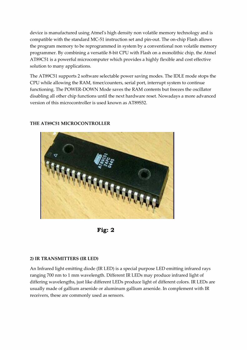
device is manufactured using Atmel's high density non volatile memory technology and is
compatible with the standard MC-51 instruction set and pin-out. The on-chip Flash allows
the program memory to be reprogrammed in system by a conventional non volatile memory
programmer. By combining a versatile 8-bit CPU with Flash on a monolithic chip, the Atmel
AT89C51 is a powerful microcomputer which provides a highly flexible and cost effective
solution to many applications.
The AT89C51 supports 2 software selectable power saving modes. The IDLE mode stops the
CPU while allowing the RAM, timer/counters, serial port, interrupt system to continue
functioning. The POWER-DOWN Mode saves the RAM contents but freezes the oscillator
disabling all other chip functions until the next hardware reset. Nowadays a more advanced
version of this microcontroller is used known as AT89S52.
THE AT89C51 MICROCONTROLLER
Fig: 2
2) IR TRANSMITTERS (IR LED)
An Infrared light emitting diode (IR LED) is a special purpose LED emitting infrared rays
ranging 700 nm to 1 mm wavelength. Different IR LEDs may produce infrared light of
differing wavelengths, just like different LEDs produce light of different colors. IR LEDs are
usually made of gallium arsenide or aluminum gallium arsenide. In complement with IR
receivers, these are commonly used as sensors.
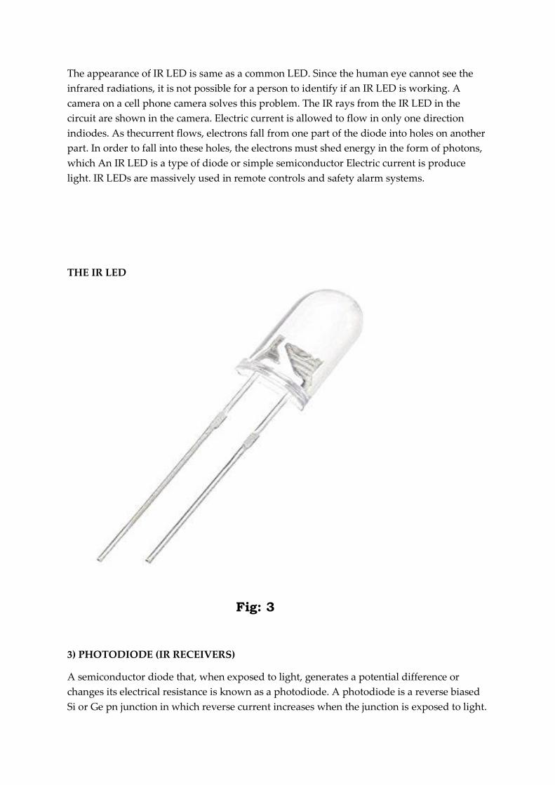
The appearance of IR LED is same as a common LED. Since the human eye cannot see the
infrared radiations, it is not possible for a person to identify if an IR LED is working. A
camera on a cell phone camera solves this problem. The IR rays from the IR LED in the
circuit are shown in the camera. Electric current is allowed to flow in only one direction
indiodes. As thecurrent flows, electrons fall from one part of the diode into holes on another
part. In order to fall into these holes, the electrons must shed energy in the form of photons,
which An IR LED is a type of diode or simple semiconductor Electric current is produce
light. IR LEDs are massively used in remote controls and safety alarm systems.
THE IR LED
Fig: 3
3) PHOTODIODE (IR RECEIVERS)
A semiconductor diode that, when exposed to light, generates a potential difference or
changes its electrical resistance is known as a photodiode. A photodiode is a reverse biased
Si or Ge pn junction in which reverse current increases when the junction is exposed to light.

When no light is incident on the pn junction of the photodiode, an extremely small amount
of reverse current is detected known as DARK CURRENT. When light is incident on the pn
junction of the photodiode there is a transfer of energy from the incident light (photons) to
the atoms in the junction. This will create more free electrons which will in turn increase the
reverse current. Whenever an obstacle (reflecting surface) comes in front of the photodiode,
these rays are reflected back and captured. When the is no obstacle they are unable to be
captured.
PHOTODIODE
Fig: 4
4) IR SENSOR
An IR sensor is a device that detects IR radiation falling on it. Proximity sensors (used in
touchscreen phones and edge avoiding robots), contrast sensors (used in line following
robots) and obstruction counters/sensors (used for counting goods and in burglar alarms)
are some applications involving IR sensors. An IR sensor consists of two parts, the emitter
circuit and the receiver circuit. This is collectively known as a photo-coupler or an
optocoupler.
The emitter is an IR LED and the detector is an IR photodiode. The IR photodiode is
sensitive to the IR light emitted by an IR LED. The photo-diode’s resistance and output
voltage change in proportion to the IR light received. This is the underlying working
principle of the IR sensor.
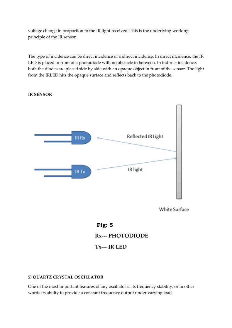
The type of incidence can be direct incidence or indirect incidence. In direct incidence, the IR
LED is placed in front of a photodiode with no obstacle in between. In indirect incidence,
both the diodes are placed side by side with an opaque object in front of the sensor. The light
from the IRLED hits the opaque surface and reflects back to the photodiode.
IR SENSOR
Fig: 5
Rx--- PHOTODIODE
Tx--- IR LED
5) QUARTZ CRYSTAL OSCILLATOR
One of the most important features of any oscillator is its frequency stability, or in other
words its ability to provide a constant frequency output under varying load

conditions.Frequency stability of the output signal can be greatly improved by the proper
selection of the components used for the resonant feedback circuit, including the
amplifier.To obtain a very high level of oscillator stability a Quartz Crystal is generally used
as the frequency determining device to produce other types of oscillator circuit known
generally as a Quartz Crystal Oscillator, (XO).When a voltage source is applied to a small
thin piece of quartz crystal, it begins to change shape producing a characteristic known as
the Piezo-electric effect. This Piezo-electric Effect is the property of a crystal by which an
electrical charge produces a mechanical force by changing the shape of the crystal and vice
versa, a mechanical force applied to the crystal produces an electrical charge.The quartz
crystal used in a Quartz Crystal Oscillator is a very small, thin piece or wafer of cut quartz
with the two parallel surfaces metallized to make the required electrical connections. The
physical size and thickness of a piece of quartz crystal is tightly controlled since it affects the
final or fundamental frequency of oscillations. The fundamental frequency is generally
called the crystals “characteristic frequency”.
QUARTZ CRYSTAL OSCILLATOR
Fig: 6
Now let us come to the main block of our project.
The highway model consists of 8 LEDs as streetlights and 8 pairs of photodiodes-IR diodes
used as sensors, and variable resistors. The IR sensors are placed on one side of the road and
the LEDs are placed on the other side of the road, directly facing the IR sensors. The device is
manufactured using Atmel's high-density nonvolatile memory technology and the IR receivers are
connected to PORT-1 of the microcontroller while the LEDs are connected to PORT-3 of the
microcontroller. The AT89C51 is a low-power, high-performance CMOS 8- bit microcontroller
with 4K bytes of in-system Flash programmabl and erasable read only memory.
WORKING IN BRIEF:
The IR transmitter is placed directly in line of sight with IR receiver, so that the IR receiver
continuously receives infrared rays. Once the IR receiver receives infrared rays, the
microcontroller will detect Logic 1. If the infrared rays are blocked by some means, the
microcontroller will detect logic 0.
So, the program for the microcontroller must be written in such a way that it will turn ON
the LEDs, which means here the street lamp, when it detects Logic 0 and it will turn OFF the
LEDs, when it detects Logic 1.Let us consider the two IR sensors i.e. IR Transmitter and IR
Receiver are placed on either side of the road. As per the circuit diagram, the IR receivers are
connected to the PORT 1 and the LEDs are connected to the PORT 3 of the microcontroller.
At the beginning, when there is no obstacle, the IR receiver continuously detects IR light
transmitted by the IR Transmitter. When a car or any other vehicle blocks any of the IR
sensors, the microcontroller will turn ON the immediate three LEDs.If the car blocks the first
IR sensor, the first three LEDs are turned ON by the microcontroller. As the car moves
forward and blocks the second IR sensor, the corresponding next three LEDs will be turned
ON and the first LED of the previous set is turned OFF. The process continues this way for
all the IR Sensors and LEDs
CIRCUIT DESIGN:
The hardware design of the circuit is centered on the 4 basic components, the AT89C52
Microcontroller, the IR Transmitters, the IR Receivers and the LEDs.In order to use the on-
chip oscillator, the microcontroller requires an external clock. This is provided by a crystal
oscillator. An 11.0592MHz quartz crystal is connected to XTAL1 and XTAL2 pins with two
33 pF ceramic capacitors connected to it. The reset circuit of the microcontroller consists of a
8.66K resistor, 10uF capacitor and a push button. The external access pin is connected to Vcc
of the circuit via a 10K resistor. The next hardware that is connected is the IR Receiver. 8 IR
receivers to the PORT 1 pins of the microcontroller. In order to use the PORT 1 as I/O port,
we need to connect external pull up resistors to the PORT 1 pins. After that, connect the

output of the IR receiver i.e. anode terminal of the photo diode to PORT 1 pins. The cathode
terminals of the photo diodes are connected to supply. Also, a 3.3K resistor is connected
between the anode terminal and ground. The next part of the circuit is IR transmitter. IR
transmitter is not a part of the microcontroller connections as the only job of the IR
transmitter is to continuously emit infrared rays. Hence the 8 IR transmitters are connected
with corresponding 8 current limiting resistors of 330 Ohms with a power supply. Finally,
the LEDs are connected. We need to connect the LED’s to the PORT 3of the microcontroller.
CIRCUIT DIAGRAM
Fig: 7
1.4 Outcome:
The primary outcome of our project is to see the streetlights glow, which are the LEDs in this case,
after the IR sensors used in the circuit have successfully detected a passing vehicle. Another
important outcome of our project work is energy conservation. This is also achieved as the LEDs
used in our circuit are automatically turned ON and OFF, thereby saving a considerable amount of
energy. Also, reduction in the maintenance cost is also achieved since the life span and durability of
LEDs are higher than that of Neon based lights which are commonly used as streetlights.
As discussed earlier the basic hardware circuit of our project consists of the microcontroller,the IR
sensors (transmitters as well as receivers) and the LEDs. After assembling these along with some
other components which are required for the creating the circuit,the complete hardware design of
the circuit is show below. We have used the upper surface of a rectangular piece of plywood to
mount the different components of the circuit.

THE FULLY OPERATIONAL HARDWARE CIRCUIT
Fig: 8

Now our project not only consists of a hardware part,it has a software part as well. The linking
between the hardware and the software part is done by the AT89C51 microcontroller. We have
programmed the microcontroller in such a way that it will turn ON the LEDs when it detects Logic 0
and turn them OFF when it detects Logic 1, which in turn are controlled by the IR sensors.
The coding for the microcontroller is done in the assembly language using the PROTEUS software
(version 7.6). The same software is also used for the software simulation of the circuit.
ASSEMBLY LANGUAGE PROGRAM OF THE MICROCONTROLLER
Fig: 9
SOFTWARE SIMULATION OF THE CIRCUIT
Fig: 10

REFERENCES
1. www.electronicshub.com
2. https://youtu.be/UMwhlHeaem0
3. https://youtu.be/c5_2ab6AKOY
4. https://youtu.be/zd1aofa7QBc
5. 8051: Microprocessors and Microcontrollers by Gaonkar
6. Official website of Atmel

CONCLUSION
By performing this project, we have studied and got to know how an IR sensor actually
works in real life. We also got to know seperately, the functionings of the microcontroller,the
IR LEDs as well as the Photodiodes. The fully operational circuit portrays a clear picture of
how actually by detecting the presence of any vehicle,the street lights which are the LEDs in
this project,are being made to glow. This street light control circuit can be used in normal
roads, highways, express ways etc. This project can also be used in parking areas of malls,
hotels, industrial lighting etc. If the lighting system implements all the LED lights, the cost of
maintenance can be reduced as the life span and durability of LEDs are higher than that of
Neon based lights which are normally used as street lights. In today's world of energy crisis
new and alternative resources to supply energy and power are being extensivel explored to
meet the growing demands of the ever increasing population. As the lights here are
automatically turned ON or OFF, huge amount of energy can be saved thus reducing the
consumption of the present resources which are decaying at an alarming rate.

ACKNOWLEDGEMENTS
It is our pleasure to thank and remain grateful to various people, professors, who directly or
indirectly contributed in the development and successful completion of this project report
and who have influenced our thinking, behavior, and acts during the course of building this
project. We would like to express our sincere gratitude to Mr. ABHISHEK BASU, HOD,
Department of Electronics and Communication Engineering, RCC Institute of Information
Technology,for providing us the opportunity, to choose this topic as our undergraduate final
year project topic, and to perform it successfully. We are grateful to Mr. SUJOY MONDAL,
Assistant Professor and UG and PG Project Coordinator, Department of Electronics and
Communication Engineering, RCC Institute of Information Technology and Mr. ANINDYA
BASU, our project mentor and guide (Assistant Professor, Department of Electronics and
Communication Engineering, RCC Institute of Information Technology) as well other
faculty members of our esteemed department for their constant support, cooperation, and
motivation, provided to us during the different phases of building the aforesaid project,
which served as a constant source of inspiration, presence and blessings. We also extend our
humble gratitude and will remain forever indebted to Mr. BUDHADITYA BISWAS,
Assistant Professor, Department of Electrical Engineering, RCC Institute of Information
Technology who provided us with his valuable suggestions and precious time in designing
this project and accomplishing our project report.