stray current interference on high speed rail transit systems and surrounding buried metallic
TRANSCRIPT


STRAY CURRENT INTERFERENCE ON HIGH-SPEED RAIL TRANSIT SYSTEMS AND SURROUNDING
BURIED METALLIC STRUCTURES
G. Santi1 and L. Sandrolini2 1C.S.F.C.E., Bologna, Italy
2Dipartimento di Ingegneria Elettrica, University of Bologna, Italy Abstract: In this paper the issue of the interference caused by stray currents generated by low-speed rail transit systems on civil works (viaducts and tunnels) of the high-speed railway system and on other surrounding and underground metallic structures (methane and gas pipe-lines, and cables) is presented. The effects of electromagnetic couplings have been considered and the protective provisions to be adopted are described. The results of d.c. interference measurements recently carried out by the authors on two critical sites of the Rome-Naples high-speed rail transit line currently under construction are presented. Keywords: Interference, stray currents, induced currents, potentials, insulating resistance, overvoltages, polarisation 1. Introduction Since 1994 the C.S.F.C.E. (Italian Commission to Study Electrolytic Corrosion Phenomena), located in Bologna, together with CESCOR s.r.l., Milan, has carried out an in-depth analysis on the Rome-Naples high-speed rail transit line. The aim of this study has been to predict the conditions of interference caused by stray currents originated by the pre-existent d.c. low-speed rail transit lines on the system civil works (viaducts and tunnels). The d.c. flowing in the soil can travel through the new high-speed rail transit system especially where there is an extended and very close parallelism between the two systems and may interfere with other surrounding or crossing metallic structures (methane and gas pipelines, and cables). The in-
1
terference of alternating stray currents generated by the high-speed traction system, operating in a.c. at a voltage of 25 kV at 50 Hz, on its own metallic structures and the surrounding or crossing buried ones owned by a third party has been outlined, too. The effects of the elec-tromagnetic induction phenomena due to such system on those structures and in particular the induced currents that have closed paths in the soil have also been considered. Taking into ac-count the combined effect of such influences, the choice of the protective provisions to be adopted has been thoroughly analysed at the design stage. C.S.F.C.E. has studied and planned appropriate measures in details, to protect the metallic reinforcements of the railway civil works. Protective provisions are necessary as the new Rome-Naples high-speed rail transit line presents numerous viaducts and galleries that are close to the pre-existent d.c. low-speed rail transit system. It is not known if other European railway systems have these critical situa-tions. By means of measurements in two critical sites of the Rome-Naples high-speed rail-way, the authors recently verified that the prescribed and afterwards adopted protective pro-visions yielded very good results in assuring the durability of the concrete reinforcements of the aforesaid works, and therefore in reducing the influence of stray d.c. and a.c. on gas and water pipelines, cables, and on their systems of cathodic protection. 2. Sources of Interference The main sources of interference on the civil works of high-speed railways and on surround-ing buried pipelines that have been considered in this paper are
• running rails of d.c. traction systems • conductors of the a.c. rail transit system (running rails, contact lines and their cate-
nary, earthing longitudinal strands, feeders) and the main receivers of disturbances are
• fixed installations and reinforced concrete civil works of the high-speed rail transit system
• buried pipelines (water and gas) • protecting tubes • cathodic protection units.
Both stray currents and electromagnetic couplings cause interference between sources and receivers. The stray currents flow in the soil and in metallic structures, which offer low elec-trical resistance paths to the current, while the electromagnetic couplings are related to time-varying electromagnetic fields. The phenomena of interference can be therefore classified as follows:
• conducted interference, generated by o d.c. sources, that can cause corrosion on bare or not perfectly insulated struc-
tures o a.c. sources, that can cause overvoltages on bare or not perfectly insulated
structures that are orthogonal or nearly orthogonal to the source of interference • capacitive coupling interference, generated by a.c. sources, with structures highly in-
sulated from the ground • inductive coupling interference, generated by a.c. sources, with structures that are
parallel or nearly parallel to the source of interference. The structures can be o earthed at both ends, not perfectly insulated or bare. The induced current flows
in the soil through the structure o insulated structures, that can be earthed at one end, subject to overvoltages.
Corrosion can occur in correspondence of pits where the density of the current leaving the metal is high.
2

The contemporaneous presence of d.c. and a.c. sources originates periodic stray currents with a d.c. component. The above described interferences can therefore be combined. 3. Conducted and Inductive Interference D.C. Interference Traction systems, such as electrical trains, tram systems and underground trains can cause d.c. conducted interference on surrounding underground steel structures. In particular, the stray current does not return to the substation (d.c. supply) through the running rails, but trav-els instead through the soil, where the metallic pipelines are located. As these metallic struc-tures have a lower electrical resistance than the soil, the stray current flows in the pipelines towards the supply station. However, real situations may be more complex. A practical, maximum limit for considering the corrosion negligible is a current density of 2 mA/m2, which corresponds to a corrosion rate of 2 µm/year [1]. As the current density cannot be easily measured, the quantity to be taken into account is the electric potential, and the cor-rosion rate can be determined by means of longitudinal voltage measurements [2]. A.C. Interference The essential parameter to be monitored is the a.c. density, related to the corrosion rate. Ac-cording to [1],[3],[4] not negligible corrosion effects appear only for densities of a.c. leaking from the metal above 100 A/m2, some orders of magnitude larger than the corresponding limit value for d.c.. These values of current density may be reached in correspondence of pits and small coating imperfections. The most effective current density and RSM potential measurement that can be carried out, especially at fixed test points, makes use of a probe called external test coupon with an elec-trode [5]. The density σ of the a.c. leaking from a pit in the structure can be determined also from the following formula [1]
σ = VF ⋅4
π r ρ
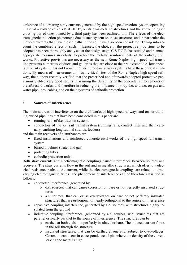
where VF is the RMS potential of the pit with respect to the remote earth, ρ is the soil electri-cal resistivity and r is the radius of the pit, assumed of circular shape. The interference generated by an a.c. rail transit line varies with the traffic conditions, there-fore it must be recorded for a suitable period of time. Overvoltages caused by conducted interferences The stray currents released by two earthing longitudinal strands may increase the potential in the surrounding points with respect to the potential of the remote earth. For instance, this po-tential increase may concern pipelines, insulated from the soil, that cross high-speed rail tran-sit lines at a right angle, as represented in Fig. 1. The value of the voltage of the pipeline to ground can be calculated if the voltage Vd of the running rails is known [6]. For example, in case of a short-circuit between the running rails and the contact line, with reference to Fig. 1, where h = 5 m, D = 12 m, L = 20 m, ρ = 100 Ω⋅m, and Vd = 1150 V, the voltage of the pipeline to ground is VC = 200 V. Therefore, the pipeline must be earthed and placed in a pro-
3
tecting tube to prevent dangerous overvoltages in case of faults [7].
rail tracks
earth longitudinalstrands
L
Dh
Φ<<L
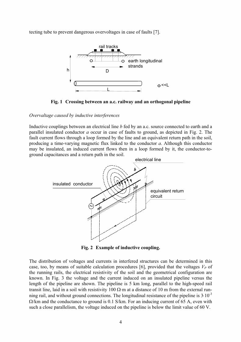
Fig. 1 Crossing between an a.c. railway and an orthogonal pipeline Overvaltage caused by inductive interferences Inductive couplings between an electrical line b fed by an a.c. source connected to earth and a parallel insulated conductor a occur in case of faults to ground, as depicted in Fig. 2. The fault current flows through a loop formed by the line and an equivalent return path in the soil, producing a time-varying magnetic flux linked to the conductor a. Although this conductor may be insulated, an induced current flows then in a loop formed by it, the conductor-to-ground capacitances and a return path in the soil.
equivalent returncircuit
insulated conductor
electrical line
b
a
Fig. 2 Example of inductive coupling.
The distribution of voltages and currents in interfered structures can be determined in this case, too, by means of suitable calculation procedures [6], provided that the voltages VP of the running rails, the electrical resistivity of the soil and the geometrical configuration are known. In Fig. 3 the voltage and the current induced on an insulated pipeline versus the length of the pipeline are shown. The pipeline is 5 km long, parallel to the high-speed rail transit line, laid in a soil with resistivity 100 Ω⋅m at a distance of 10 m from the external run-ning rail, and without ground connections. The longitudinal resistance of the pipeline is 3⋅10-3 Ω/km and the conductance to ground is 0.1 S/km. For an inducing current of 65 A, even with such a close parallelism, the voltage induced on the pipeline is below the limit value of 60 V.
4

0 1 2 3 4 50
10
20
30
40
50[V]
[A]
[km]
| V |
| I |
.
.
Fig. 3 Current and voltage magnitudes along the pipeline.
Prescribed voltage in case of interference The Italian provisional standard CEI 9-34 [8] prescribes limits of the voltage to earth of con-ductive parts of buried installations in order to avoid electrical shocks to people and corrosion damages. The limits are different in case of normal use and fault conditions, as reported in Tab. I, where the voltages are RMS values.
Tab. I. Voltage to earth limits prescribed by the Italian provisional standard CEI 93-4.
People Structures
Normal use 60 V 60 V for the voltage to remote earth 50 V for the voltage to earth on the
measuring site Conditions of
fault 430 ÷ 2000 V for switch inter-
vention time between 1 s and 0.1 s 2000 V for the voltage to remote
earth 500 V for insulating joints
2000 V for monolithic joints
4. D.C. Interference on high-speed rail transit lines and surrounding buried metal-lic structures The fixed installations of new high-speed rail transit systems (running rails, lightning protec-tion strands, earthing rods, electrical equipments) have interconnections to the earthing longi-tudinal strands through the support structures. The pre-existent d.c. field generated by old low-speed rail transit lines is therefore distorted and the high-speed line installations can rep-resent lower impedance return paths to the rectifier station. In particular, this occurs when the distance between the low- and high-speed rail transit lines is very small, i.e., at the junctions between railways, at crossings with bridges (see Fig. 4), and in all those cases where the two lines are close and parallel for long distances. The stray d.c. generated by the low-speed rail transit line can also leave the high-speed line and interfere with metallic pipelines that cross or are close to it, as depicted in Fig. 5.
5

Slow-speed railtransit line
High-speed railtransit line tunnel rectifier station
stray d.c.
stray d.c.
Fig. 4 D.C. Interference induced by a low-speed rail transit line on a high-speed rail transit line.
low-speed railtransit line
high-speed railtransit line
substation
stray d.c.current stray d.c.
currentpipeline
Fig. 5 Stray d.c. interference on a high-speed rail transit line and on a pipeline.
The corrosion effects related to this interference on the pipeline are much more critical than those from stray a.c. originated by the high-speed rail transit line. Nevertheless, the a.c. cor-rosion effects can combine with the d.c. ones producing more severe corrosion attacks on in-sulated pipelines, especially where the coating presents pits or porosity. 5. A.C. Interference on cathodic protection systems An important issue related to stray a.c. interferences is their influence on the correct operation of cathodic protection systems. In particular, the Graetz bridge of the supply system rectifies the stray a.c. that flows in the circuit pipeline-a.c. source. Malfunctions can then occur in the cathodic protection system, with irregular changes in the electrical state of the pipelines [9].
6
6. Protective provisions for high-speed rail transit systems and surrounding metal-lic structures In order to minimize the interference effects from the running rails, the earthing longitudinal strands and the ground connections of the 2 x 25 kV system chosen for the new Italian high-speed railway, appropriate provisions were adopted at the design stage:
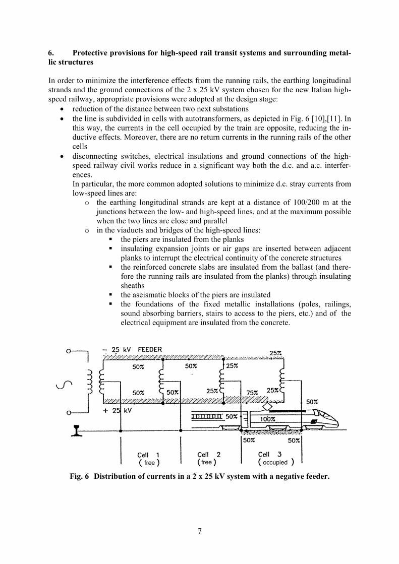
• reduction of the distance between two next substations • the line is subdivided in cells with autotransformers, as depicted in Fig. 6 [10],[11]. In
this way, the currents in the cell occupied by the train are opposite, reducing the in-ductive effects. Moreover, there are no return currents in the running rails of the other cells
• disconnecting switches, electrical insulations and ground connections of the high-speed railway civil works reduce in a significant way both the d.c. and a.c. interfer-ences. In particular, the more common adopted solutions to minimize d.c. stray currents from low-speed lines are:
o the earthing longitudinal strands are kept at a distance of 100/200 m at the junctions between the low- and high-speed lines, and at the maximum possible when the two lines are close and parallel
o in the viaducts and bridges of the high-speed lines: the piers are insulated from the planks insulating expansion joints or air gaps are inserted between adjacent
planks to interrupt the electrical continuity of the concrete structures the reinforced concrete slabs are insulated from the ballast (and there-
fore the running rails are insulated from the planks) through insulating sheaths
the aseismatic blocks of the piers are insulated the foundations of the fixed metallic installations (poles, railings,
sound absorbing barriers, stairs to access to the piers, etc.) and of the electrical equipment are insulated from the concrete.
Fig. 6 Distribution of currents in a 2 x 25 kV system with a negative feeder.
7

Reduction of stray a.c. potential gradients The poles of the traction system are earthed with earthing rods to protect people and installa-tions in case of fault. The earthing rods are connected together through an earthing longitudi-nal strand. In this way, the fault current flows through these low resistance conductors reduc-ing the electrical potential gradient near poles, supports, railings, etc. Reduction of inductive couplings The contact line and the feeder are positioned close together to reduce the area of the induc-ing loop. The lightning protection strand is also positioned close to the contact line and its catenary to reduce inductive effects in the occupied cell, minimizing therefore the interfer-ence on any circuit parallel to the line (shielding effect). Provisions for adjacent metallic structures (pipelines and cables) Structures with an insulating coating that are parallel to the interfering high-speed line must be subdivided in electrically insulated sections. The stray currents in these structures are then reduced as well as the voltage to ground. Structures that cross the running rails are laid or-thogonally to them in a protecting tube and sectioned at the two ends of the crossing [3]. In order to assure people safety, the voltage of the pipeline to ground can be reduced by means of several ground connections. However, the efficiency of the cathodic protection worsens, as the resistance to ground decreases. To avoid this, a voltage limiter (polarization cell) must be installed between the pipeline and each ground connection [3]. 7. Protective provisions for low-speed rail transit systems and surrounding metallic structures Some of the protective provisions prescribed by the CENELEC standard to minimize stray currents caused by d.c. railways require to mantain [2]:
• a high level of insulation of the running rails and of the whole return circuit from earth
• an adequate clearance between ballast and running rails • an effective water drainage • the conductance per unit length values of running rails and return circuits • appropriate insulation of the equipment connected to the running rails, relative to
foundations that are earthed. 8. Results of measurements carried out to verify the interference caused by d.c. rail transit lines D.C. Interference on the Rome-Naples high-speed line In the Autumn 2001, the authors performed some measurements in two sites of the Rome-Naples high-speed rail transit line under construction, near the town of Frosinone. The sites were assessed as critical, because the viaducts of the new high-speed line could be exposed to potential attacks of corrosion for the extended parallelism and the close proximity with the
8

low-speed line and its substations. These two sites are unique in the whole Rome-Naples high-speed line, and are both located between Anagni and Ceprano, as represented in Fig. 7:
• viaduct VI33 “S. Maria”, located near the small town of Anagni, on the junction be-tween the odd rail track of the low-speed line and the high-speed line. The ballast was not laid yet
• viaduct VI53 “Sul Liri”, located near the village of Ceprano. Ballast and running rails were already laid.
In the former there is a close parallelism among the high-speed line viaduct VI33, the viaduct of the low-speed line and two viaducts of the interconnection line between the low- and high-speed lines. In the latter, the parallelism is between the viaduct VI53 and the one of the low-speed line, both on the river Liri. This parallelism becomes very close near the railway station of Ceprano. The measurements were carried out to assess the conditions of interference on the reinforced concrete viaducts and concerned
• verification of the electrical continuity of the plank reinforcements • verification of the electrical insulation between reinforcing rods of adjacent planks • verification of the electrical insulation between reinforcing rods of planks and their
piers • verification of the electrical insulation of railings • measurement of the electrical potential gradient of the surrounding soil • measurement of the polarisation potential against the concrete of reinforcements of
adjacent parts.
substations
Zagarolo
Colleferro
Anagni Morolo
CepranoHigh-speed line
Low-speed line
ROME NAPLES
Fig. 7 Draft of the low- and high- speed lines between Rome and Naples.
Polarisation of reinforcing rods The results of the measurements show that the reinforcing rods of the same plank are bonded together correctly, as recommended at the design stage, and that
• the reinforcing rods are in conditions of immunity, and corrosion can be excluded • significant stray d.c. from the low-speed rail transit line were not ascertained.
The polarisation potential was recorded for a time interval large enough to include the most intense traffic conditions. In Fig. 8 and in Fig. 9 two recordings of the polarisation potential of the reinforcing rods with respect to the concrete versus time are represented, related to the viaducts VI53 and VI33, respectively. These potential recordings, measured at the ends of the planks, have been chosen among the others as the most significant ones. The small potential variations that can be noted in the curves of Fig. 8 and Fig. 9 are originated by the transit of trains on the low-speed line. The maximum variation of the steady state potential is 20 mV
9
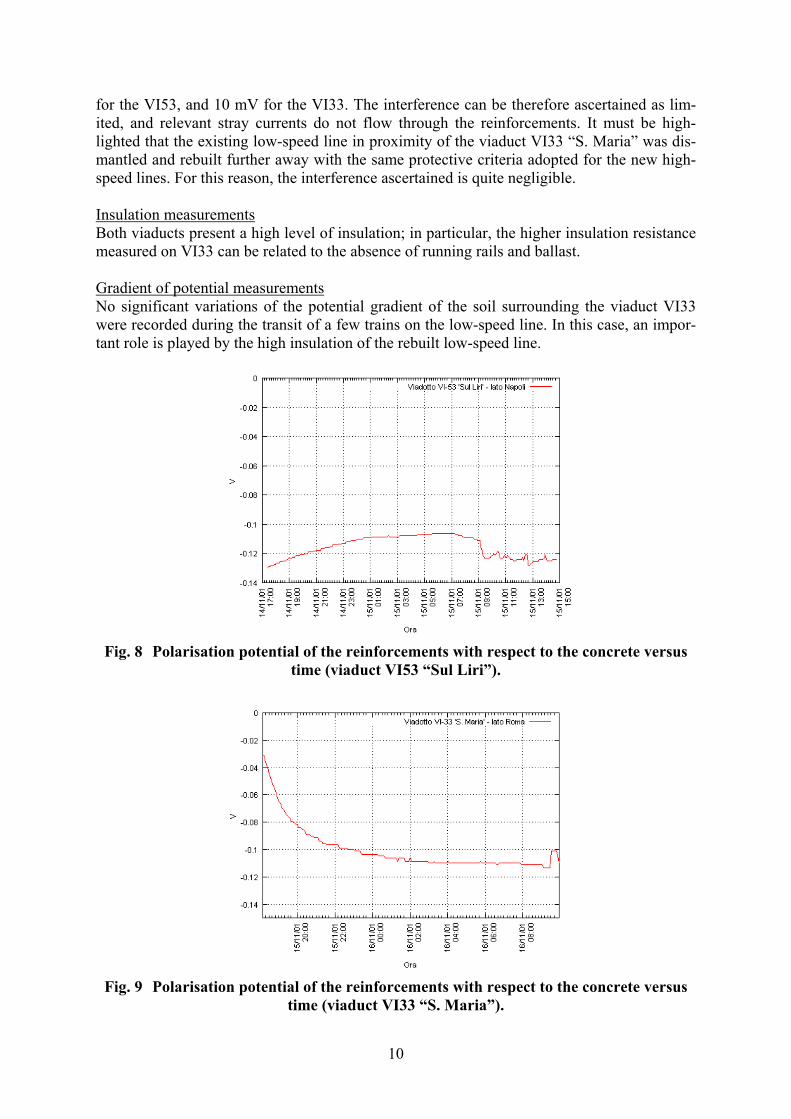
for the VI53, and 10 mV for the VI33. The interference can be therefore ascertained as lim-ited, and relevant stray currents do not flow through the reinforcements. It must be high-lighted that the existing low-speed line in proximity of the viaduct VI33 “S. Maria” was dis-mantled and rebuilt further away with the same protective criteria adopted for the new high-speed lines. For this reason, the interference ascertained is quite negligible. Insulation measurements Both viaducts present a high level of insulation; in particular, the higher insulation resistance measured on VI33 can be related to the absence of running rails and ballast. Gradient of potential measurements No significant variations of the potential gradient of the soil surrounding the viaduct VI33 were recorded during the transit of a few trains on the low-speed line. In this case, an impor-tant role is played by the high insulation of the rebuilt low-speed line.
Fig. 8 Polarisation potential of the reinforcements with respect to the concrete versus
time (viaduct VI53 “Sul Liri”).
Fig. 9 Polarisation potential of the reinforcements with respect to the concrete versus
time (viaduct VI33 “S. Maria”).
10
It can be concluded that both a correct preparation of the concrete and the reinforcements and the protective provisions adopted have contributed to minimize the interference even in case of extended parallelisms or close proximity between the low- and the high-speed lines. It is therefore unlikely that the new high-speed lines can significantly modify the interference generated by the pre-existent low-speed lines on buried pipelines that are parallel or cross the high-speed lines. Nevertheless, interference can be considered particularly reduced as
• the new high-speed lines have a large number of viaducts and tunnels which are accu-rately electrically insulated from the soil
• the crossings between the low- and high-speed railways take place by means of bridges which are electrically insulated from the soil in a way similar to that of the viaducts
• the sections of the low-speed line that had an extended parallelism with the new high-speed line have been dismantled and rebuilt further away with the same protective cri-teria of the new lines.
Feeding tests of the new high-speed line are still in progress and therefore the consequences of a.c. interferences on the electrical state of buried pipelines with cathodic protection sys-tems are not well known yet. 9. Conclusions All the provisions described above are useful to reduce the interference, in order to assure people safety as well as to reduce the risk of corrosion of the conductive structures. Suitable algorithms can be used to predict the alterations of the electrical state of the structures and therefore to adopt effective provisions at the planning stage [6]. These calculations are sig-nificant only if many data are known, such as the geometrical configuration of the installa-tions, the kind of material used, the properties of the soil and the characteristics of the inter-fered and interfering installations. The a.c. interference is dangerous for the safety of people, in particular in case of faults, and in a few cases in combination with d.c. sources can also cause corrosion of buried metallic structures not correctly insulated or protected. The meas-urements illustrated in this paper show that an accurate design of all the structures involved gives satisfactory results and assures the required protection level. Acknowledgment The authors wish to thank Prof. U. Reggiani, of the Department of Electrical Engineering, University of Bologna, for useful discussions and suggestions, and Mr L. Di Biase, of Snam Rete Gas S.p.A., for important clarifications. References
[1] L. Lazzari, P. Pedeferri, Protezione Catodica (Cathodic Protection), McGraw-Hill Libri, Milan, Italy, 2000.
[2] CEI EN 50122 –2, “Applicazioni ferroviarie, tramviarie, filoviarie e metropolitane – impianti fissi – Parte II. – protezione contro gli effetti delle correnti vaganti cau-sate da sistemi di trazione a corrente continua” (Railway application - Fixed instal-lation – Part 2: Protective provisions against the effects of stray currents caused by d.c. traction systems), 1999.
11

[3] C.S.F.C.E. – CEOCOR, Guida pratica della protezione catodica (Practical Guide to Cathodic Protection), Bologna, Italy,1995.
[4] P. Pedeferri, L. Bertolini, La durabilità del calcestruzzo armato (The Durability of the Reinforced Concrete), McGraw-Hill Libri Italia, Milan, Italy, 2000.
[5] C.S.F.C.E. – CEOCOR, Guida delle tecniche di misura della protezione catodica (Guide to the Measurement Tecniques of Cathodic Protection), Bologna, It-aly,1995.
[6] R. Benato, R. Caldon, A. Paolucci, “Algoritmo matriciale per l’analisi di una linea ferroviaria ad alta velocità e rispettiva rete di alimentazione,” Energia Elettrica, Vol. 75, n. 5. Sept-Oct. 1998.
[7] UNI 9783, “Protezione catodica di strutture metalliche interrate. Interferenze elet-triche tra strutture metalliche interrate” (Cathodic protection of buried metallic structures. Electrical interference among buried metallic structures), 1990.
[8] Italian provisional standard CEI 9-34 , “Effetti delle interferenze elettromagnetiche provocate da linee di trazione ferroviarie elettrificate in corrente alternata su tuba-zioni. Valori ammissibili e provvedimenti di protezione” (Effects of electromag-netic interferences caused by a.c. railway contact lines on pipelines. Prescribed val-ues and protection provisions), 1997.
[9] D. Gentile, F. Martini, L. Mosca, “Effetti delle interferenze elettromagnetiche sui sistemi elettrici in corrente alternata su alimentatori e dispositivi di protezi-one catodica”, in II Convegno Nazionale APCE, Rome, Italy, 21-22 Nov. 1996.
[10] V.Morelli, “Il sistema di alimentazione dell’ A.V. - Configurazioni adottate per limitare le interferenze elettromagnetiche”, in II Convegno Nazionale APCE, Rome, Italy, 21-22 Nov. 1996.
[11] F. Perticaroli, “Sistemi di alimentazione delle linee ferroviarie europee”, Ingegneria Ferroviaria , Oct. 1994, pp.539-544.
12