stratus elevator installation and operation manual … · stratus elevator installation and...
TRANSCRIPT

Rev Dec. 16, 15
STRATUS ELEVATOR
Installation and Operation Manual
Copyright 2015

RAM Manufacturing Ltd. 1-800-563-4382 1 | P a g e
STRATUS ELEVATOR INSTALLATION AND OPERATION MANUAL
Contents
Section 1: Introduction .............................................................................................................. 2
Section 2: Safety ........................................................................................................................ 2
Section 3: Operating Instructions .............................................................................................. 3
Section 4: Site Preparation ........................................................................................................ 5
Section 5: Installation .............................................................................................................. 11
Section 6: Tower Splitting ........................................................................................................ 29
Section 7: Commissioning and Trouble-Shooting .................................................................... 35
Section 8: Maintenance ........................................................................................................... 52
Appendix A: Assembly Drawings................................................................................................... 53
Appendix B: Maintenance Log ...................................................................................................... 55

RAM Manufacturing Ltd. 1-800-563-4382 2 | P a g e
STRATUS ELEVATOR INSTALLATION AND OPERATION MANUAL
Section 1: Introduction
Thank you for selecting the STRATUS elevator. When operated properly the STRATUS elevator
is designed to provide years of trouble free service. This manual is provided to show you how
to operate the elevator safely and efficiently. Please read this manual thoroughly before
installing and operating your elevator for the first time. We recommend your elevator be
installed and serviced by a qualified service technician. If you are having problems installing the
elevator call our tech support line at 1-800-563-4382.
Section 2: Safety
Read all instructions thoroughly before installation or use of this elevator. Failure to do so
could result in serious injury or death.
Refer to local building codes, elevator codes and elevator authorities to ensure installation
is safe and meets your local regulations.
We recommend your elevator be installed and serviced by a qualified service technician.
Do not override any of the safety devices provided with the elevator
The elevator is intended for use to a maximum of 800 lb.
(DO NOT OVERLOAD THE ELEVATOR).
Make sure that passengers are completely inside the car before raising or lowering the
elevator.
This list may not be exhaustive, due care around mechanical equipment should be
observed. If uncertain, please contact the manufacture or a qualified installer.
For product updates and bulletins, please refer to our website www.trustram.com

RAM Manufacturing Ltd. 1-800-563-4382 3 | P a g e
STRATUS ELEVATOR INSTALLATION AND OPERATION MANUAL
Section 3: Operating Instructions
A key switch is provided to prevent unauthorized use of the Elevator. The key is removable in both positions. When you wish to use the elevator, insert the key and turn the switch to ON, and remove the key. It is recommended that you have the key readily available whenever operating the elevator.
Go inside the car and close the landing door and car door if provided or make sure the light curtain is clear if provided.
Press button of your destination floor (1, 2 or 3) once. The elevator will move automatically and stop at the selected floor.
If you need to stop the elevator any time by pressing the red STOP button (See Figure 1). To release, simply pull out the button.
An object blocking the light curtain or opening of the carriage gate will also cause the elevator to stop, it will automatically proceed to the selected floor once the light curtain is clear or the carriage gate is fully closed
Figure 1: COP Overview

RAM Manufacturing Ltd. 1-800-563-4382 4 | P a g e
STRATUS ELEVATOR INSTALLATION AND OPERATION MANUAL
MANUAL CRANK OPERATION
If a power outage occurs while the elevator is in use and a passenger is stranded between
landings, the car can be manually lowered or raised using the Hand Crank Tool provided. First
verify manual cranking is required, ensure;
all landing doors are fully closed
light curtain path is clear (if provided)
carriage gate is fully closed (if provided)
the COP stop button is pulled out
the control key is turned on
breakers are in the ON position
panel disconnect is in the ON position
manual crank is disengaged
If manual cranking is still required follow these steps:
All passengers inside the car must keep away from the car entrance when
the car is moving.
Figure 2: Manual Crank Overview
Insert the hand crank tool (3/8” drive extension and ratchet) into the manual crank access hoistway located outside the hoistway on the top landing
Push in and rotate to engage the crank and raise or lower the car until the landing floor.
Open the landing door and car gate (if provided) to evacuate the passengers.
To disengage the crank reverse the cranking for approximately 5 rotations until the shaft springs back into the neutral position

RAM Manufacturing Ltd. 1-800-563-4382 5 | P a g e
STRATUS ELEVATOR INSTALLATION AND OPERATION MANUAL
Section 4: Site Preparation
4.1 Tools and Hardware for Installation
Tool list for elevator installation
1” x 48” lifting belt 2 pcs
Hoisting Tool 1 unit
Electric Hand Drill and Drill bit 3/8” x 12” 1 set
Phillip Screw driver 1 pc
#2 Robinson Screw Driver 1 pc
Socket Ratchet Wrench 1 set
3/8” – ¾” Hand Wrenches 1 set
Drywall Saw 1 unit
25’ x 1” Measuring Tape 1 pc
48” Level 1 pc
Broom and Dust Pan 1 set
24ft Extension Ladder 1 unit
60” Step Ladder 1 unit
Trouble Light 1 pc
Utility Knife 1 pc
Combination Wire Stripper/Crimper
Concrete Drill with 3/8” x 12” concrete bit (for concrete wall only)
90 Ft. 14Ga. extension Cord
Hardware and additional parts for elevator installation (included with elevator package)
Wood Studs 2” x 4” x 8’ 5 pcs
(can use crate material)
# 10 x 3 ½” wood screws 50 pcs
Carriage bolt 3/8”-16 x 8” 2 pcs (Top Tower Anchor)
3/8” nut, flat & lock washer 2pcs each
# ¼ x 3” lag bolt w/washer 20 pcs (for wood frame only)
3/8 x 1-7/8” Conc. Block Anchor 20 pcs (for concrete wall only)
Steel Shims for bottom tower 6 pcs (UG166)
Wood Shims for back tower 1 bundle (for wood frame only)
Steel Shims for Back tower 20 pcs (for concrete wall only)

RAM Manufacturing Ltd. 1-800-563-4382 6 | P a g e
STRATUS ELEVATOR INSTALLATION AND OPERATION MANUAL
4.2 Layout and Hoistway Measurement
Measure all dimensions of the hoistway and check with layout drawing (Refer to:
Installation Details drawing).
Check inside hoistway dimensions on all floors. Check hoistway height and overhead
clearance. Check door opening positions. All dimensions should be within the
tolerance +1/2” and -0”.
No. Car Size Hoistway Size (inside, Width x Depth)
1 36” x 48” x 84” 50 ½” x 53 ½”
2 40” x 54” x 84” 54 ½” x 59 ½”
3 40” x 60” x 84” 54 ½” x 65 ½”
Table 1: Hoistway Size
No. Max. Travel Tower Height L
Bottom Tower Height Lb
Min. Overhead Clearance
1 Up to 9’ (108”) 164” (13’8”) 80” (6’8”) 92”
2 Up to 11’ (132”) 188” (15’8”) 104” (8’8”) 92”
3 Up to 14’ (168”) 224” (18’8”) 140” (11’8”) 92”
Table 2: Tower Height & Min. Overhead Clearance
Make sure the area where you are working is clean. Sweep out the pit if necessary,
and clean the area where your parts are going to be placed.
Check installation drawing for hoistway dimensions and guide rail locations.
Measure the hoistway along its full length at 24” intervals making sure that all four
walls are parallel, square and plumb, and the dimensions match the installation
drawings.
Measure distance to each landing from the bottom of pit to the top of the finished
floor, the distance from the pit floor to the finished top floor is the most critical.
Measure clearance from the finished top floor to the hoistway ceiling, a minimum of
92” is required.
RAM Manufacturing Ltd. 1-800-563-4382 7 | P a g e
STRATUS ELEVATOR INSTALLATION AND OPERATION MANUAL
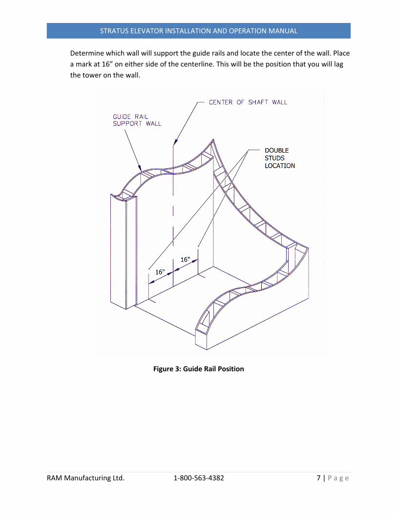
Determine which wall will support the guide rails and locate the center of the wall. Place
a mark at 16” on either side of the centerline. This will be the position that you will lag
the tower on the wall.
Figure 3: Guide Rail Position

RAM Manufacturing Ltd. 1-800-563-4382 8 | P a g e
STRATUS ELEVATOR INSTALLATION AND OPERATION MANUAL
4.3 Installation Clearance Checking
Check the installation clearance in front of the existing hoistway entrance
(Entrance Cut-out of entrance: min. 35” x 81 1/5”). Compare with the dimension
of tower or bottom tower height (Refer to: Table 2)
If the clearance is enough, go to Section 5: Installation.
If the clearance is not enough, go to Section 6: Tower Splitting.
Figure 4: Installation Clearance

RAM Manufacturing Ltd. 1-800-563-4382 9 | P a g e
STRATUS ELEVATOR INSTALLATION AND OPERATION MANUAL
4.4 Upper Junction Box Cut-out in the Hoistway
Make a cut-out (Refer to Figure 5: 13 1/4”x 21 1/2”) on the top of tower wall for Upper
junction Box. Refer to the location shown below. The cut-out should be between
middle studs and right side studs and the cut-out start from either side of the studs by
13 1/4” wide. The bottom of the cut-out is about 12 1/2” higher above the top of the
Tower.
If alternate location for the Upper Junction Box, please contact RAM manufacturing
for detail.
Figure 5: Cut-out for Upper Junction Box

RAM Manufacturing Ltd. 1-800-563-4382 10 | P a g e
STRATUS ELEVATOR INSTALLATION AND OPERATION MANUAL
4.5 Preparation for Hoisting Tower
Step 1: Install 1 - 2” x 4” wood stud on both side of the hoistway approximately 12”
below the ceiling using 6 wood screws #10 x 3-½” (catch 3 studs- 2screws/stud). (Note:
Use alternate anchoring means for non-wood stud walls. Fix another 3 pcs (hoisting
beam Item 4) in center position on top the installed studs. Refer to the drawing below.
Figure 6: Hoisting Beam Installation
1 Hoistway 2 2” x 4” Wood Stud (1 pc)
3 2” x 4” Wood Stud (1 pc) 4 2” x 4” Wood Stud (3 pcs)
Hoisting Beam
RAM Manufacturing Ltd. 1-800-563-4382 11 | P a g e
STRATUS ELEVATOR INSTALLATION AND OPERATION MANUAL
Section 5: Installation
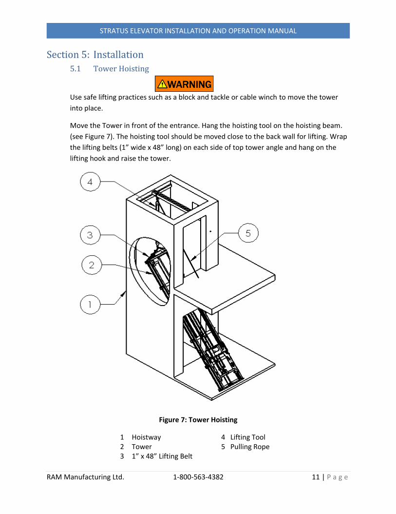
5.1 Tower Hoisting
Use safe lifting practices such as a block and tackle or cable winch to move the tower
into place.
Move the Tower in front of the entrance. Hang the hoisting tool on the hoisting beam.
(see Figure 7). The hoisting tool should be moved close to the back wall for lifting. Wrap
the lifting belts (1” wide x 48” long) on each side of top tower angle and hang on the
lifting hook and raise the tower.
Figure 7: Tower Hoisting
1 Hoistway 2 Tower 3 1” x 48” Lifting Belt
4 Lifting Tool 5 Pulling Rope

RAM Manufacturing Ltd. 1-800-563-4382 12 | P a g e
STRATUS ELEVATOR INSTALLATION AND OPERATION MANUAL
5.2 Tower Attachment
Position tower on tower wall according to the dimension “G” (surface of Guide Rail Tube
to surface of hoistway entrance wall) on the layout drawing. Check this dimension on
each floor and adjust the tower accordingly. If it is a through car, make this dimension
equal on both entrance sides.
Put shims on bottom of tower if necessary, so that tower is relaxed in correct
position.
Begin lagging to wall starting from the second bracket from the top and working
down using ¼” ex lag screw (or use 1/4” anchor bolts for concrete wall)
Shim wall brackets by wood shims to prevent pulling tower
Figure 8: Tower Attachment (Top)
1 Top Tower 2 Carriage Bolt 3/8”-16 x 8”
(for Top Attachment only)
3 Washer/Lock washer/Nut

RAM Manufacturing Ltd. 1-800-563-4382 13 | P a g e
STRATUS ELEVATOR INSTALLATION AND OPERATION MANUAL
Figure 9: Tower Attachment (Bottom)
1 Bottom Tower 2 Hoistway Wall
3 Wide Washer 1/4” 4 Hex Lag Screw ¼”-20 x 3”
Figure 10: Tower Attachment (with Wood Shim)
1 Tower 2 Lag Bolt ¼”x 3” 3 Wide Washer ¼”
4 Wood Shim 5 Hoistway Wall

RAM Manufacturing Ltd. 1-800-563-4382 14 | P a g e
STRATUS ELEVATOR INSTALLATION AND OPERATION MANUAL
5.3 Electrical Wiring
Step 1: Install the upper junction box in the cut-out on the hoistway wall. Set the
surface of the junction box to protrude 3/4” past the wall exterior and check the door of
the junction box opened freely.
Figure 11: Upper Junction Box Installation

RAM Manufacturing Ltd. 1-800-563-4382 15 | P a g e
STRATUS ELEVATOR INSTALLATION AND OPERATION MANUAL
Step 2: Upper Junction Box Connections
Connect travelling cable - Plug
Connect door Teck-cables – Plug
Connect Motor – Plug
Connect Manual Crank & Belt Switch - Plug
Connect 220V/1PH/20A power - Hardwired by Others
Figure 12: Upper Junction Box Connections
1 Tower 2 Hoistway 3 Travelling Cable
4 Upper junction Box 5 Door Teck-Cable 6 Motor Flex 7 Manual Crank and Belt Switch

RAM Manufacturing Ltd. 1-800-563-4382 16 | P a g e
STRATUS ELEVATOR INSTALLATION AND OPERATION MANUAL
5.4 Manual Crank Installation
Install the manual crank on top of tower, refer to installation detail below. Mark
the manual crank hoistway position on the wall and drill a hole (DIA. 1”) through
the wall. *Hint* Install the support plate in the opposite hole set to aid in finding
hole center.
Figure 13: Manual Crank Installation
1 Manual Crank Assembly 2 Tower 3 Drive Screw
4 Brake 5 Hoistway

RAM Manufacturing Ltd. 1-800-563-4382 17 | P a g e
STRATUS ELEVATOR INSTALLATION AND OPERATION MANUAL
Manual Crank Installation Detail
Figure 14: Manual Crank Installation Detail
1 Support Plate 2 Hex Bolt/Nut 3 Reducer 4 Crank Assembly 5 Hex Nut 6 Universal Coupler 7 Bracket Assembly
8 Guide Plate 9 Screw 10 Spring 11 Collar 12 Guide Plate 13 Screw 14 Manual Crank Hoistway

RAM Manufacturing Ltd. 1-800-563-4382 18 | P a g e
STRATUS ELEVATOR INSTALLATION AND OPERATION MANUAL
Manual Crank Activated
Use 3/8” wrench and extension to connect it with manual crank shaft, push and
rotate it to lower the car up or down.
Figure 15: Manual Crank Activated
1 Manual Crank Assembly 2 Spring 3 Support Plate
4 Drive Screw 5 Hoistway

RAM Manufacturing Ltd. 1-800-563-4382 19 | P a g e
STRATUS ELEVATOR INSTALLATION AND OPERATION MANUAL
Manual Crank Released
In the normal working status of the elevator, the manual crank is released. The
support plate #3 will rotate about 15 degree by the force of the spring #2. The crank
must be rotated in the reverse direction approx. 5 revolutions to fully disengage.
Figure 16: Manual Crank Released
1 Manual Crank Assembly 2 Spring 3 Support Plate
4 Drive Screw 5 Hoistway

RAM Manufacturing Ltd. 1-800-563-4382 20 | P a g e
STRATUS ELEVATOR INSTALLATION AND OPERATION MANUAL
5.5 Platform Installation
Step 1: Slide the platform into place and lower the guide frame into position using the
manual crank. Attach the platform to the Guide Frame by Hex Bolt ½”-13 x 1 ½”.
Figure 17: Platform Installation
1 Platform 2 Guide Frame
3 Hex Bolt ½”-13 x 1 ½” 4 Nut on Guide Frame

RAM Manufacturing Ltd. 1-800-563-4382 21 | P a g e
STRATUS ELEVATOR INSTALLATION AND OPERATION MANUAL
Step 2: Level the deck
Manually crank the platform up so that you can access the bottom side of the platform.
Adjust the level of the platform using the tilt bolts (Item 3 – Figure 19) 3/8”-16 x 1” on
both side of the platform until the outside edge of the platform is approx. ¼” above
level when car is empty. Balance the tension on each levelling bolt to ensure a rigid
platform.
Figure 18: Platform Levelling
1 Platform 2 Guide Frame
3 Hex bolt 3/8”-16 x 1”
5.6 Car Installation
The car has been pre-assembled and all wall panels will be marked with number tapes
that were cut prior to being disassembled and packaged.
Step 1. Assemble wall panels to Platform and Roof Frame matching corresponding
number tapes. All bolts are to be finger tight only.
Step 2. Place the four 2x4 pre-cut and marked studs vertically in the four corners of the
carriage to set the car height. These studs will be packaged with the car panels. Note: it
is important to set the correct carriage height to ensure easy removal of the Control
Wall Panel for maintenance.
Step 3. Tighten car panel bolts beginning from the bottom taking care to line up the
number tapes.

RAM Manufacturing Ltd. 1-800-563-4382 22 | P a g e
STRATUS ELEVATOR INSTALLATION AND OPERATION MANUAL
Figure 19: Car Structure Detail (In/Out-TR with Light Curtain)
1 Platform 2 End Wall 3 Control Wall Back 4 Control Wall Front 5 Side Wall Back
6 Side Wall Front
7 Front Wall 8 Roof Frame 9 Header Angle 10 Sill 11 Roof Panel 12 Control Wall

RAM Manufacturing Ltd. 1-800-563-4382 23 | P a g e
STRATUS ELEVATOR INSTALLATION AND OPERATION MANUAL
5.7 COP Installation
Install the COP on control wall: connect the COP plug and attach COP plate
through control wall to guide frame by screws.
Figure 20: COP Installation
1 COP 2 Stainless Steel Screw #10-32 x 2”
3 Control Wall 4 Guide Frame
RAM Manufacturing Ltd. 1-800-563-4382 24 | P a g e
STRATUS ELEVATOR INSTALLATION AND OPERATION MANUAL
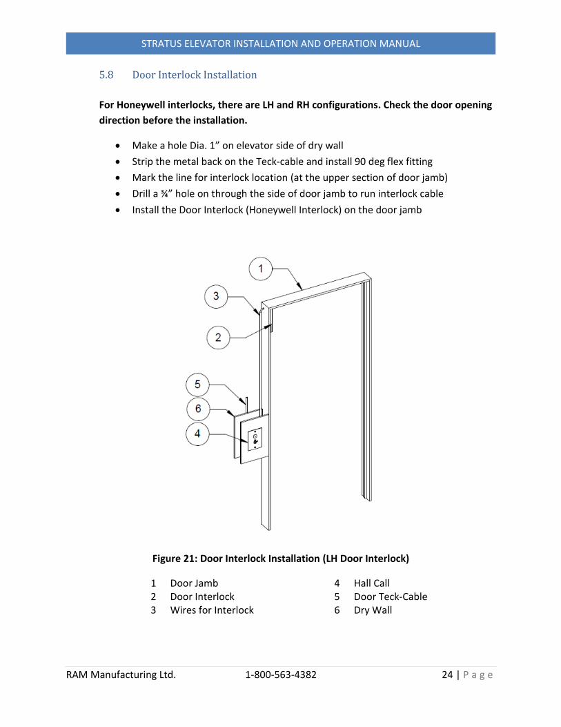
5.8 Door Interlock Installation
For Honeywell interlocks, there are LH and RH configurations. Check the door opening
direction before the installation.
Make a hole Dia. 1” on elevator side of dry wall
Strip the metal back on the Teck-cable and install 90 deg flex fitting
Mark the line for interlock location (at the upper section of door jamb)
Drill a ¾” hole on through the side of door jamb to run interlock cable
Install the Door Interlock (Honeywell Interlock) on the door jamb
Figure 21: Door Interlock Installation (LH Door Interlock)
1 Door Jamb 2 Door Interlock 3 Wires for Interlock
4 Hall Call 5 Door Teck-Cable 6 Dry Wall

RAM Manufacturing Ltd. 1-800-563-4382 25 | P a g e
STRATUS ELEVATOR INSTALLATION AND OPERATION MANUAL
After installing the interlock, locate the beak location and mark the position on
the door panel
Install the Beak for the door lock on the door panel
Drill ¾” Dia hole thru door panel to line up with interlock emergency access
Install Emergency access cover plate on outside of door
Figure 22: Door Beak Installation
1 Door Jamb 2 Door Panel
3 Beak 4 Wood Screw

RAM Manufacturing Ltd. 1-800-563-4382 26 | P a g e
STRATUS ELEVATOR INSTALLATION AND OPERATION MANUAL
Figure 23: Door Emergency Access
1 Door Jamb 2 Door Panel
3 Interlock
RAM Manufacturing Ltd. 1-800-563-4382 27 | P a g e
STRATUS ELEVATOR INSTALLATION AND OPERATION MANUAL
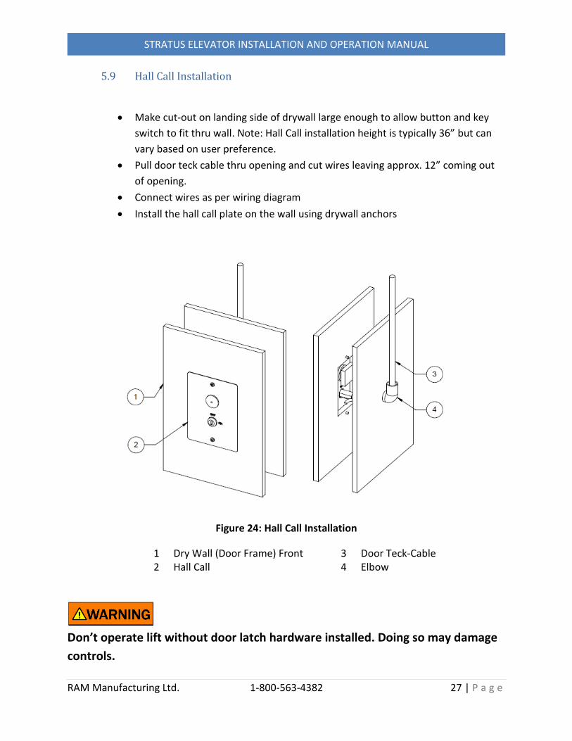
5.9 Hall Call Installation
Make cut-out on landing side of drywall large enough to allow button and key
switch to fit thru wall. Note: Hall Call installation height is typically 36” but can
vary based on user preference.
Pull door teck cable thru opening and cut wires leaving approx. 12” coming out
of opening.
Connect wires as per wiring diagram
Install the hall call plate on the wall using drywall anchors
Figure 24: Hall Call Installation
1 Dry Wall (Door Frame) Front 2 Hall Call
3 Door Teck-Cable 4 Elbow
Don’t operate lift without door latch hardware installed. Doing so may damage
controls.

RAM Manufacturing Ltd. 1-800-563-4382 28 | P a g e
STRATUS ELEVATOR INSTALLATION AND OPERATION MANUAL
5.10 Tower Safety Bolt Installation
Drill a hole Dia. 3/8” through the wall from inside hoistway based on the hole in the top
back plate on both side of the tower. Insert the carriage bolt through the wall from
outside wall and tighten the bolt by washer and nut.
Figure 25: Tower Attachment Detail (Top)
1 Top Tower 2 Carriage Bolt 3/8”-16 x 8” 3 Wide Washer 3/8”/Nut 3/8”-16
4 Dry Wall inside 5 2” x 6” Wood Stud 6 Dry Wall outside

RAM Manufacturing Ltd. 1-800-563-4382 29 | P a g e
STRATUS ELEVATOR INSTALLATION AND OPERATION MANUAL
Section 6: Tower Splitting
6.1 Splitting the Tower
Splitting the tower is only necessary if the assembled tower cannot be stood up in the
shaft in one piece.
Step 1: Remove the Guide Frame
Remove upper travelling cable clamp
Figure 26: Remove Upper Travelling Cable Clamp
1 Travelling Cable 2 Clamp
3 Screw #10-32 x ¾” 4 Tower

RAM Manufacturing Ltd. 1-800-563-4382 30 | P a g e
STRATUS ELEVATOR INSTALLATION AND OPERATION MANUAL
Remove rear slider pins and reed switch bracket on both sides
Figure 27: Remove Slider and Bracket from Guide Frame
1 Guide Frame 2 Slider Assembly 3 Slider Shaft
4 Cotter Clip 5 Reed Switch Bracket 6 Screw # 10-24 x ¾”
Remove Back Bushing
Figure 28: Remove Back Bushing from Guide Frame
1 Guide Frame 2 Back Bushing
3 Hex Bolt ¼”-20 x 1 ½” (with Flat Washer ¼”)

RAM Manufacturing Ltd. 1-800-563-4382 31 | P a g e
STRATUS ELEVATOR INSTALLATION AND OPERATION MANUAL
Remove the 4 hex bolts and nuts on the drive nut
Figure 29: Remove Guide Frame
1 Guide Frame 2 Drive Nut MT015
3 Hex Bolt 5/16”-18 x 4” 4 Nut 5/16” (with Flat Washer 5/16”, Wide Flat
Washer 5/16”, Spring 71509)
Release the spring loaded slider tension.
Figure 30: Spring Loaded Slider
1 Guide Frame 2 Moving Slider Assembly
3 Spring 1791 4 Hex Bolt ½”-13 x 1”

RAM Manufacturing Ltd. 1-800-563-4382 32 | P a g e
STRATUS ELEVATOR INSTALLATION AND OPERATION MANUAL
Remove Guide Frame from tower
Step 2: Remove Drive Screw with Stabilizer
Remove one side of the bottom guide rail for stabilizer
Figure 31: Remove one Guide Rail of Stabilizer
1 Back Plate on Tower 2 Guide Rail of Stabilizer
3 Drive Screw
Remove the clip pin and clevis pin between drive screw and shaft. Pull down the
drive screw by 1 inch to separate from Drive shaft.
Figure 32: Uninstall the Screw
1 Drive Screw 2 Drive Shaft 3 Bushing
4 Clevis Pin 5/16” x 1 3/8” 5 Hitch Pin Clip #16

RAM Manufacturing Ltd. 1-800-563-4382 33 | P a g e
STRATUS ELEVATOR INSTALLATION AND OPERATION MANUAL
Lift screw out and keep stabilizer intact to prevent drive screw from bending
Step 3: Remove Tower Connection Bolts
Remove the bolts and nuts between top tower and bottom tower
Separate top tower from bottom tower and move them into hoistway one by
one.
Figure 33: Separate the top Tower from bottom Tower
1 Top Tower 2 Bottom Tower 3 Hex Bolt
4 Hex Nut 5 Angle

RAM Manufacturing Ltd. 1-800-563-4382 34 | P a g e
STRATUS ELEVATOR INSTALLATION AND OPERATION MANUAL
6.2 Tower Re-Assembly
Reassemble the tower into the shaft following the above steps in reverse order. Take
care to align the top and bottom tower sections with smooth joint transitions.
Note: There must be ¾” gap between upper and lower drive nut when assembled to
the guide frame.
When attaching the travel cable check to make sure that it goes below the 2” tube on
guide frame when the guide frame is at the lowest position.
Figure 34: Travelling Cable Length Setting
1 Tower 2 2” Tube on Guide Frame
3 Travelling Cable

RAM Manufacturing Ltd. 1-800-563-4382 35 | P a g e
STRATUS ELEVATOR INSTALLATION AND OPERATION MANUAL
Section 7: Commissioning and Trouble-Shooting
7.1 Controller operation
Wiring
The Controller runs on 24vdc. The inputs are all 24vdc. The outputs are all relay out, dry
contact, except for the Floor indicating and door Solenoid outputs. The Floor indicator and door
Solenoid outputs are 24vdc current limited and short circuit protected.
Parameter setting
There is a four digit display to read the parameters and settings. Underneath the display are
five push buttons. Four directional, UP, DOWN, LEFT, RIGHT and one labeled E for ENTER. The
Parameters are scrolled through using the UP and DOWN buttons while the values can be
adjusted with the UP and DOWN buttons. To save the changes push the ENTER button. Make
the appropriate parameter settings before running the lift for the first time.
Figure 35: LED Display in Controller
1 Tower 2 Guide Frame
3 Controller Box 4 LED Display on PCB

RAM Manufacturing Ltd. 1-800-563-4382 36 | P a g e
STRATUS ELEVATOR INSTALLATION AND OPERATION MANUAL
Parameter Display Description
*P1 runX Machine will run in this mode. X = 0 indicates the safety circuit is not made up. X = 1 indicates the safety circuit is made up. P2 FL x Top floor x = 2 to 5 P3 t cP Constant Pressure t Au Automatic Residential *P4 ctxx xx = counter value display. 0 on 1st Floor and 8 on 2nd floor.
Add 8 for every floor. *P5 5Lxx xx = Solenoid monitoring voltage display. Reads normally about 10 volts if not activated, 22 volts if on at a landing. P6 t0 This is always displayed for this parameter. t1 By entering 1, the lift will run for 15 days. t2 The lift will run for 45 days. t3 The lift will run for 90 days. T4 Pay Program Removed. P7-11 These parameters select which gates open at which floor. P7 F1 x Floor 1: x = n for no Gate, 1 for GT1, 2 for GT2, 3 for GT3 P8 F2 x Floor 2: x = n for no Gate, 1 for GT1, 2 for GT2, 3 for GT3 P9 F3 x Floor 3: x = n for no Gate, 1 for GT1, 2 for GT2, 3 for GT3 P10 F4 x Floor 4: x = n for no Gate, 1 for GT1, 2 for GT2, 3 for GT3 P11 F5 x Floor 5: x = n for no Gate, 1 for GT1, 2 for GT2, 3 for GT3 P11 LocH Honeywell door solenoid. Maintained output at floor. LocE Euchner door solenoid. 1 minute time out at floor. P12 tE5t Used to enter test mode. *P13 ErXX Last error display. This parameter indicates the last error condition. If an error occurs the display changes to this display.

RAM Manufacturing Ltd. 1-800-563-4382 37 | P a g e
STRATUS ELEVATOR INSTALLATION AND OPERATION MANUAL
Er 1 Error 1 is a door solenoid reed switch welded contact indication. One or more of RS1-5 are closed out of the landing zone.
Er 2 Error 2 is the solenoid power was on when it should be off. Caused by either a jumped out circuit or a faulty output on the board.
Er 3 Error 3 is caused by the lift motor running for more than 2 minutes
indicating a problem with the motor and or drive. Er 4 Error 4 is the gate monitoring fault. The gate input and the gate monitoring input should activate at the same time. If there is a difference between these inputs that indicates a faulty switch. The contacts must cycle properly once to remove this error. Er 6 Error 6 is the terminal switch fault. If both switches are activated
ER 06 fault will occur and will clear when only one terminal switch is activated.
Er 7 Error 7 is displayed when the lift run timer has run out. *P14 PPXX XX is the number of days left for the lift to run. PP-- Pay program off. Lift will run and not time out.. *Display Only

RAM Manufacturing Ltd. 1-800-563-4382 38 | P a g e
STRATUS ELEVATOR INSTALLATION AND OPERATION MANUAL
Gate Safety
The Controller monitors the Gate Safety Switch. If the Gate Safety Switch welds closed the lift
will not allow a call to be made. Once the gate has cycled proving the Gate Safety Switch
integrity a new call can be made.
Door Lock Monitoring Safety.
The controller monitors the Door Solenoid Reed Switch. If the Reed Switch fails closed the lift
will stop. The problem must be solved before the lift will move.
Floor Counting
The controller clears the count to 0 on the Lower Terminal Switch. The count is increased by 4
when the counting magnet passes the encoder reed switches. This causes a count of 8 between
landings. The Upper terminal switch also sets the count to the top floor count.
Homing the Lift
The lift will Home at the first level on the first cycle after power up using slow speed. In
constant pressure mode the lift travel to the bottom no matter which call is pressed. Once the
bottom floor is reached the lift will travel to the desired call. In automatic mode, when any call
is made the lift will travel to the bottom first. Then a new call can be made to any level.

RAM Manufacturing Ltd. 1-800-563-4382 39 | P a g e
STRATUS ELEVATOR INSTALLATION AND OPERATION MANUAL
7.2 Setting the Floor Positions
*Note* Prior to setting the floor positions, set the operation of the car to constant pressure (P3=t cP) on the carriage control board to control the car movement.
The floor stopping positions and door unlocking zones are determined by reed sensors and
magnets. When the sensor registers a magnet, it changes the state of a form C contact (single
pole double throw) and signals the controller.
Setting floor positions – Terminology
There are six (seven for 3 stop elevators) reed sensors mounted to the back side of the guide
frame – ref. figure 36:
Upper terminal reed sensor – signals the controller that the car has reached the top
floor position
Lower terminal reed sensor – signals the controller that the car has reached the bottom
floor position
Encoder A and Encoder B reed sensors – determines the direction of travel and the car
position in between the top and bottom floor positions
Upper, Lower and Mid door reed sensors – send power to the corresponding door
interlock when car is at the landing

RAM Manufacturing Ltd. 1-800-563-4382 40 | P a g e
STRATUS ELEVATOR INSTALLATION AND OPERATION MANUAL
Guide Frame – sensor locations
Figure 36: Guide frame rear view – sensor location
1 – Encoder A - Reed Sensor 5 – Mid Door Reed Sensor 2 – Encoder B - Reed Sensor 6 – Upper Door Reed Sensor 3 – Lower Terminal Reed Sensor 7 – Lower Door Reed Sensor 4 – Upper Terminal Reed Sensor
1
2 3
4
5 6 7

RAM Manufacturing Ltd. 1-800-563-4382 41 | P a g e
STRATUS ELEVATOR INSTALLATION AND OPERATION MANUAL
Figure 37 – Tower: magnet mounting components
1 – Upper door reed sensor magnet mounting angle 2 – Mid door reed sensor magnet mounting angle 3 – Lower door reed sensor magnet mounting angle 4 – Left 1” SQ tube, terminal reed sensor magnet mounting tube 5 – Right 1” SQ tube, encoder A&B reed sensor magnet mounting tube
5
4
1
2
3
RAM Manufacturing Ltd. 1-800-563-4382 42 | P a g e
STRATUS ELEVATOR INSTALLATION AND OPERATION MANUAL
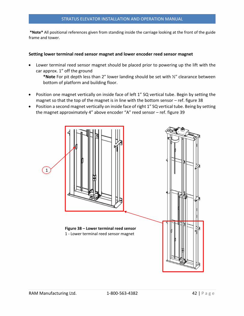
*Note* All positional references given from standing inside the carriage looking at the front of the guide frame and tower.
Setting lower terminal reed sensor magnet and lower encoder reed sensor magnet
Lower terminal reed sensor magnet should be placed prior to powering up the lift with the car approx. 1” off the ground
*Note For pit depth less than 2” lower landing should be set with ½” clearance between bottom of platform and building floor.
Position one magnet vertically on inside face of left 1” SQ vertical tube. Begin by setting the magnet so that the top of the magnet is in line with the bottom sensor – ref. figure 38
Position a second magnet vertically on inside face of right 1” SQ vertical tube. Being by setting the magnet approximately 4” above encoder “A” reed sensor – ref. figure 39
Figure 38 – Lower terminal reed sensor 1 - Lower terminal reed sensor magnet
1

RAM Manufacturing Ltd. 1-800-563-4382 43 | P a g e
STRATUS ELEVATOR INSTALLATION AND OPERATION MANUAL
*Note: terminal reed sensor must be clear of terminal reed sensor magnet before the encoder sensor is activated by the encoder magnet when leaving the landing – both sensors registering will cause a position count error. Start with a large distance between two magnets and close gap by making minor adjustments.
Once the initial position of the terminal stop and counter magnets are set, make minor adjustments:
Make minor adjustments to the lower floor stopping position by raising the carriage above the landing and moving the lower terminal reed sensor magnet vertically along the tube. Lower the carriage to the new stopping position. Repeat until the platform stops level with the landing as desired
1
Figure 39 – Lower encoder reed sensor 1 – Lower encoder reed sensor magnet

RAM Manufacturing Ltd. 1-800-563-4382 44 | P a g e
STRATUS ELEVATOR INSTALLATION AND OPERATION MANUAL
Setting upper terminal reed sensor magnet and upper encoder reed sensor magnet
Stop the lift when the platform is approximately level with the upper landing and position one magnet vertically on inside face of left 1” SQ vertical tube. Begin by setting the magnet so that the bottom of the magnet is in line with the top of the upper terminal reed sensor. – ref. figure 40
Position a second magnet vertically on inside face of right 1” SQ vertical tube – approximately 4” below encoder “B” reed sensor. – ref. figure 41
1
Figure 40 – Upper terminal reed sensor 1 – Upper terminal reed sensor magnet

RAM Manufacturing Ltd. 1-800-563-4382 45 | P a g e
STRATUS ELEVATOR INSTALLATION AND OPERATION MANUAL
*Note: terminal reed sensor must be clear of terminal reed sensor magnet before the encoder sensor is activated by the encoder magnet when leaving the landing – both sensors registering will cause a position count error. Start with a large distance between two magnets and close gap by making minor adjustments.
Once the initial position of the terminal stop magnet and upper count magnet are set, make minor adjustments:
Make minor adjustments to the upper floor stopping position by lowering the carriage below the landing and then moving the upper terminal stop magnet vertically along the tube. Move the carriage upwards again until it stops. Repeat until the platform stops level with the landing
1
Figure 41 – Upper encoder reed sensor 1 – Upper encoder reed sensor magnet

RAM Manufacturing Ltd. 1-800-563-4382 46 | P a g e
STRATUS ELEVATOR INSTALLATION AND OPERATION MANUAL
Mid floor settings Mid floor settings are used when the lift is to stop at a landing other than the upper or lower
landing. Two (2) magnets are used with an encoder reed sensor to ensure the lift stops at the
correct location when coming from either the upper or lower landing.
Position upper encoder reed sensor magnet vertically on inside face of right 1” SQ vertical tube so that car stops at the mid floor level. Move the lift above the mid floor landing and return, making minor adjustments to the magnet position until the carriage stops level when traveling down from the upper landing.
Position a lower encoder reed sensor magnet approximately 6” below the upper encoder reed sensor magnet. Move the lift below the mid floor landing and return making minor adjustments to the magnet position until the carriage stops level with the landing when traveling up from the lower landing. Ref – figure 42
Figure 42 – Mid-floor encoder reed sensor
1 – Mid floor upper encoder reed sensor magnet 2 – Mid floor lower encoder reed sensor magnet
1
2

RAM Manufacturing Ltd. 1-800-563-4382 47 | P a g e
STRATUS ELEVATOR INSTALLATION AND OPERATION MANUAL
Door reed sensor settings
With the lift stopped flush with landing, place one magnet vertically on the outside face of 1” floor reed sensor angle. Position magnet so that the sensor is centered on the magnet
Repeat steps for each floor by moving the lift to next landing and placing another magnet on the floor reed angle, ensuring the sensor is located at the center of the magnet
*NOTE: door will not open unless the corresponding door reed switch is in the magnet zone
3
1
2
Figure 43 – Door reed sensors
1 – Upper encoder door reed sensor magnet 2 – Mid position encoder door reed sensor magnet 3 – Lower encoder door reed sensor magnet

RAM Manufacturing Ltd. 1-800-563-4382 48 | P a g e
STRATUS ELEVATOR INSTALLATION AND OPERATION MANUAL
Upper final switch setting
The upper final switch is a limit switch that is triggered by a mechanical stop if the lift tries to
advance past the upper floor terminal setting.
Upper mechanical stop setting
Stop lift at the highest point of desired travel – the upper landing
Position upper final bracket (mechanical stop) so that it is just touching, but not depressing the trigger rod of the upper final switch
Mark mounting holes on the tower using the bracket as a guide
Drill mounting hole and install mechanical stop bracket on the tower guide rail by ¼”-20 x 1” Hex bolts and lock washers
Figure 44 – Upper Final Limit Switch and Mechanical Stop
1 Mechanical Stop Bracket 2 ¼” -20 x 1” Hex Bolt/Lock Washer 3 Guide Frame
4 Upper Limit Switch 5 Tower

RAM Manufacturing Ltd. 1-800-563-4382 49 | P a g e
STRATUS ELEVATOR INSTALLATION AND OPERATION MANUAL
Lower final switch setting
The lower final switch is a limit switch that is triggered by the red back-up nut safety bracket
when the carriage makes contact with the pit floor or lower mechanical stop
Lower mechanical stop setting
Red back-up nut safety bracket is set in factory to engage at the pit or shaft floor. If pit is deeper than 2” install blocking to stop car from travelling more than ½” past bottom landing.
*NOTE: once all magnets are set correctly, secure them to angle using silicone or glue to ensure they do not vibrate out of position. *NOTE: all photos are locational references for mounting the magnets, position will change depending on specific instillation.
Figure 45 – Lower mechanical stop
1 – Back-up nut safety bracket 2 – Lower final limit switch
1
2

RAM Manufacturing Ltd. 1-800-563-4382 50 | P a g e
STRATUS ELEVATOR INSTALLATION AND OPERATION MANUAL
7.3 Auto-tuning the Emerson drive to motor
Lower the car with no load to the bottom floor.
Manually hold in M3 to power up the drive.
Press the “M” button and the display should read the parameter # on the left and the value on the right.
Using the UP and DOWN arrows get to P41. Press “M”.
Change the value to “Ur A” press “M” to enter.
Using the UP and DOWN arrows get to P38. Press “M”.
Change the value to “2” press “M” to enter.
Release M3
Press the top floor selection
The motor will rotate for about 10 seconds then stop, drive readout=iH000.
For constant pressure lifts release the floor selection. For automatic lifts press the e-stop.
If the display reads iH 000 then auto-tune is complete. If not press the reset button and repeat procedure.
Verify operation by running again, Drive should show motor amperage.
Auto tuning is now complete.

RAM Manufacturing Ltd. 1-800-563-4382 51 | P a g e
STRATUS ELEVATOR INSTALLATION AND OPERATION MANUAL
7.4 Trouble Shooting
Upper Junction Box
Check the status of LED’s on the Upper junction Box to located on the exterior of the
hoistway. A red light indicates an open circuit and must be investigated.
Figure 37: LED on Upper Junction Box
1 Car Stop Switch 2 Manual Crank Switch 3 Belt Switch
4 Door 1 Switch 5 Door 2 Switch 6 Door 3 Switch
Carriage Junction Box
If the problem is not resolved by checking the status of LED’s on the Upper junction, remove the
carriage control wall panel to access the PCB controller. You must unplug the COP when removing
the panel. The LED indicators on this panel correspond to inputs on the electrical schematics
supplied with your elevator. The LED for input “SC” must be brightly lit for the elevator to
operate. Any red LED indicates an open circuit or problem that must be investigated.

RAM Manufacturing Ltd. 1-800-563-4382 52 | P a g e
STRATUS ELEVATOR INSTALLATION AND OPERATION MANUAL
Section 8: Maintenance
8.1 Monthly Inspection
Inspect all gates/doors and ensure they are locked when the elevator is not
at the landing. Also check that the elevator will not run unless the gates /
doors are fully closed and locked.
8.2 Annual Maintenance
The STRATUS Elevator should be inspected and maintained annually.
Inspect the drive nuts – refer to drive nut inspection procedure
Lubricate Drive Screw (Light lubrication with Teflon-oil based spray lubricant)
Inspect the drive belt for wear. A small amount of black rubber bits below the
belt is normal. If there is any significant sign of wear to the belt, replace it.
Lubricate the Upper Screw Thrust Bearing (Grease nipple located on underside of
bearing plate).
8.3 Maintenance Log
Please keep a record of all maintenance done on the elevator in the
maintenance log provided in Appendix C.
8.4 Spare Parts
All parts below are used for maintenance, contact manufacturing for orders.
Drive nuts
Ceiling LED fixture
Drive Belt
Domed Call Button
RAM Manufacturing Ltd. 1-800-563-4382 53 | P a g e
STRATUS ELEVATOR INSTALLATION AND OPERATION MANUAL
Appendix A: Assembly Drawings
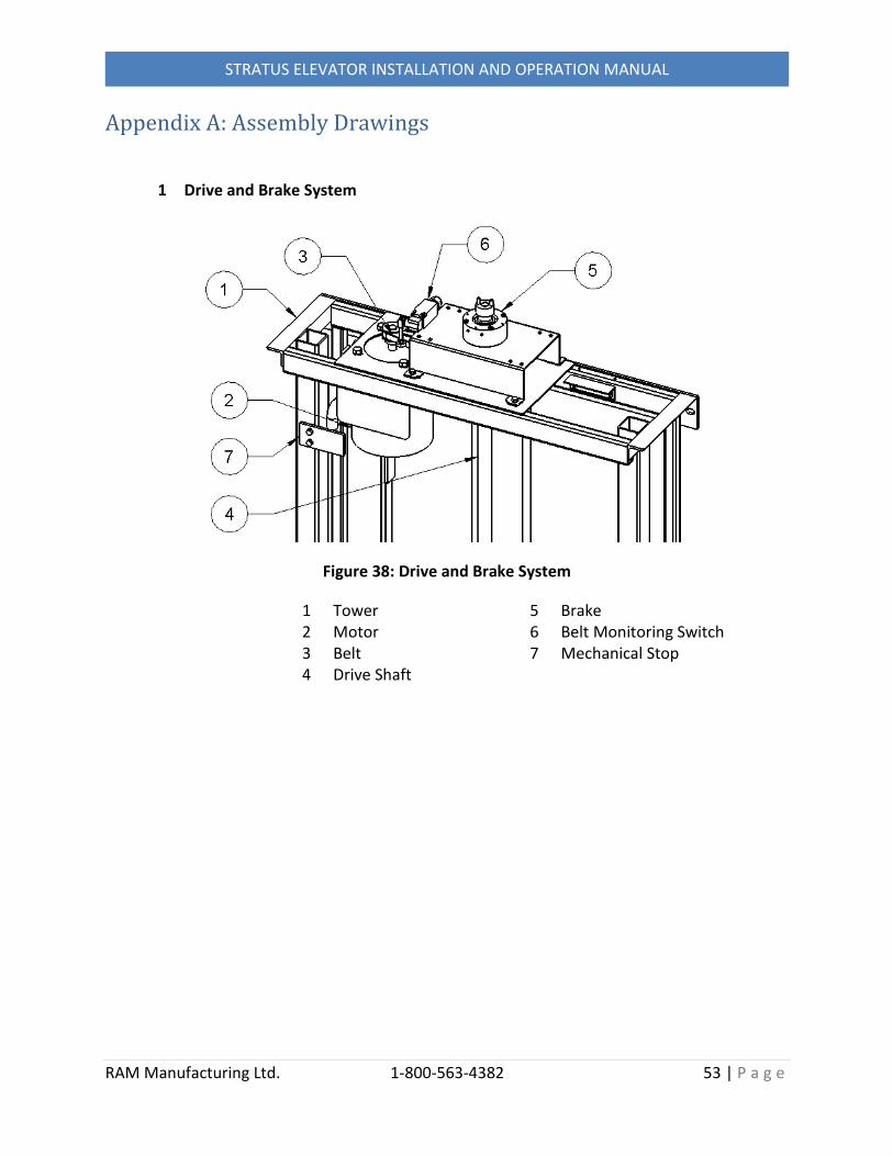
1 Drive and Brake System
Figure 38: Drive and Brake System
1 Tower 2 Motor 3 Belt 4 Drive Shaft
5 Brake 6 Belt Monitoring Switch 7 Mechanical Stop

RAM Manufacturing Ltd. 1-800-563-4382 54 | P a g e
STRATUS ELEVATOR INSTALLATION AND OPERATION MANUAL
2 Control System
Figure 39: Control System
1 Hoistway Wall 2 Upper Junction Box 3 Main Switch 4 Lock
5 LED 6 UPS 7 PLC
Figure 40: Controller
1 Tower 2 Guide Frame
3 Controller Box with PCB

RAM Manufacturing Ltd. 1-800-563-4382 55 | P a g e
STRATUS ELEVATOR INSTALLATION AND OPERATION MANUAL
Appendix B: Maintenance Log Date Description Signed