stratified forming as a tool for resource efficient papermaking
TRANSCRIPT
Stratified Forming as a Tool for Resource Efficient Papermaking
Marco Lucisano, Daniel Söderberg, Hannes Vomhoff, Lennart Hermansson, Fredrik Rosén, Ida Östlund,
Elisabeth Björk, Karin Athley and Bo NormanInnventia, Stockholm (Sweden)This is a copy of my presentation at TAPPI
PaperCon 2015. I have added speech bubbles to guide you through the slides.
Please feel free to contact me if you have questions and comments: [email protected]
2
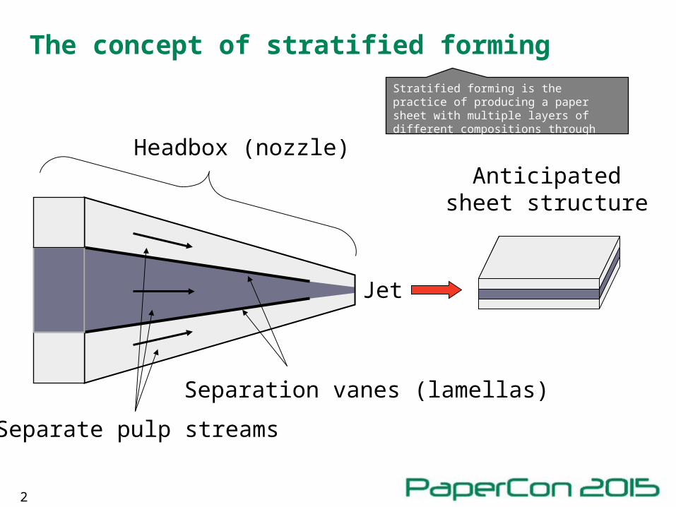
Separation vanes (lamellas)
Anticipated sheet structure
Jet
Separate pulp streams
Headbox (nozzle)
The concept of stratified forming
Stratified forming is the practice of producing a paper sheet with multiple layers of different compositions through one single headbox.
3
Why stratified forming?
4
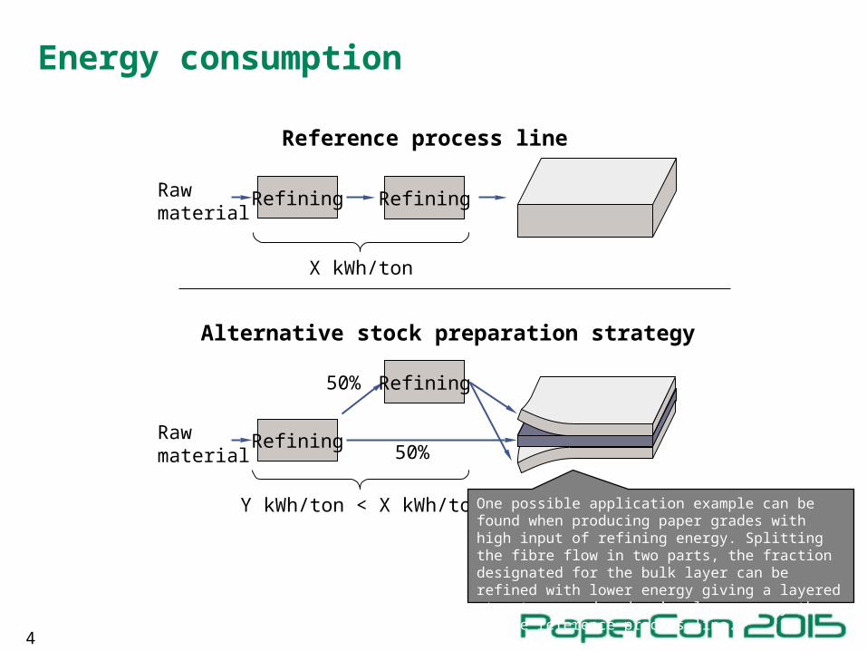
RefiningRaw material
Refining
X kWh/ton
RefiningRaw material
Refining50%
50%
Y kWh/ton < X kWh/ton
Energy consumption
Reference process line
Alternative stock preparation strategy
One possible application example can be found when producing paper grades with high input of refining energy. Splitting the fibre flow in two parts, the fraction designated for the bulk layer can be refined with lower energy giving a layered structure produced using less energy than in the reference process line.
5
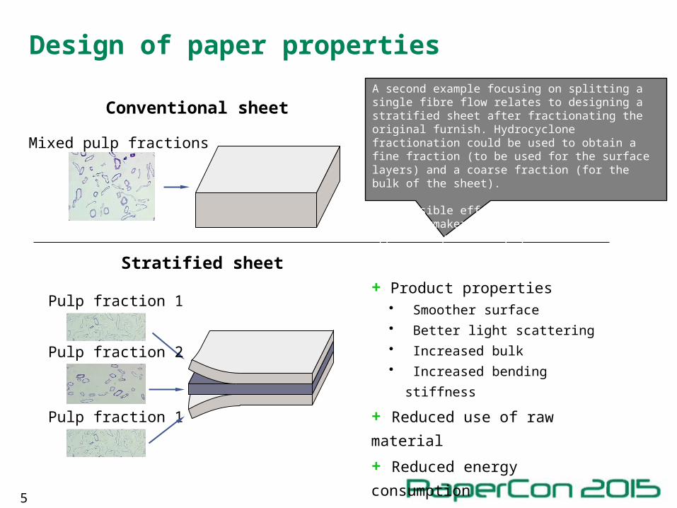
+ Product properties • Smoother surface• Better light scattering• Increased bulk • Increased bending stiffness
+ Reduced use of raw material
+ Reduced energy consumption
Conventional sheet
Stratified sheet
Pulp fraction 1
Pulp fraction 1
Pulp fraction 2
Mixed pulp fractions
Design of paper properties
A second example focusing on splitting a single fibre flow relates to designing a stratified sheet after fractionating the original furnish. Hydrocyclone fractionation could be used to obtain a fine fraction (to be used for the surface layers) and a coarse fraction (for the bulk of the sheet).
The possible effects, listed below, give the papermaker a new intriguing opportunity to design products.
6
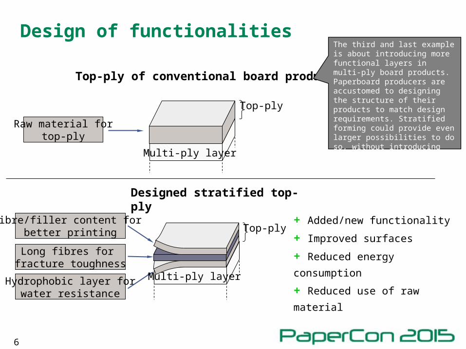
Top-ply of conventional board product
Raw material fortop-ply
Long fibres for fracture toughness
Fibre/filler content for better printing
Designed stratified top-ply
+ Added/new functionality
+ Improved surfaces
+ Reduced energy consumption
+ Reduced use of raw materialHydrophobic layer for
water resistance
Multi-ply layer
Top-ply
Multi-ply layer
Top-ply
Design of functionalitiesThe third and last example is about introducing more functional layers in multi-ply board products. Paperboard producers are accustomed to designing the structure of their products to match design requirements. Stratified forming could provide even larger possibilities to do so, without introducing additional headboxes and wire sections.
7
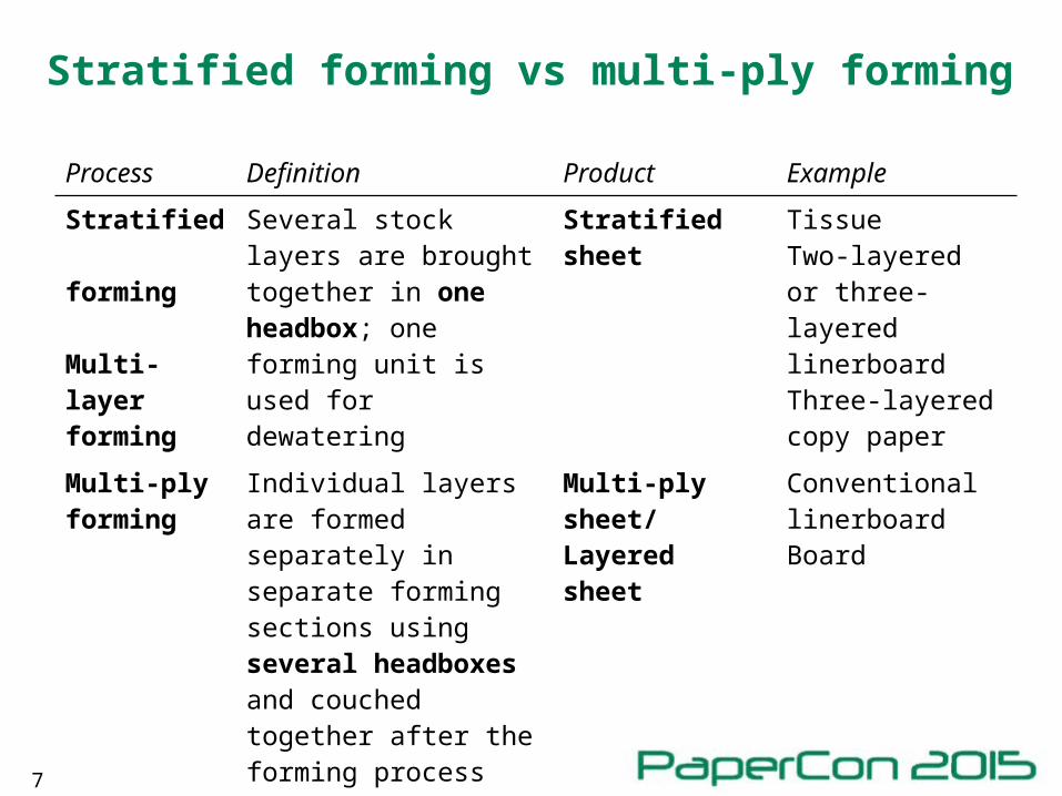
Stratified forming vs multi-ply forming
Process Definition Product Example
Stratified forming
Multi-layer forming
Several stock layers are brought together in one headbox; one forming unit is used for dewatering
Stratified sheet TissueTwo-layered or three-layered linerboardThree-layered copy paper
Multi-ply forming
Individual layers are formed separately in separate forming sections using several headboxes and couched together after the forming process
Multi-ply sheet/Layered sheet
Conventional linerboardBoard
8
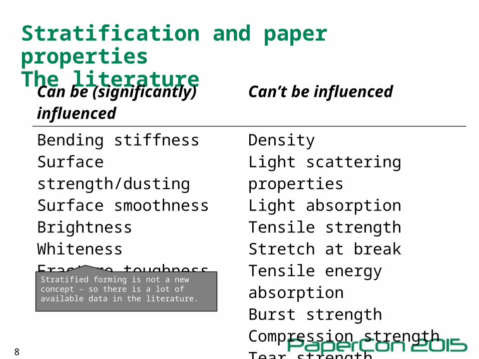
Stratification and paper propertiesThe literature
Can be (significantly) influenced
Can’t be influenced
Bending stiffnessSurface strength/dustingSurface smoothnessBrightnessWhitenessFracture toughnessZ-strength
DensityLight scattering propertiesLight absorptionTensile strengthStretch at breakTensile energy absorptionBurst strengthCompression strengthTear strength
Stratified forming is not a new concept – so there is a lot of available data in the literature.

9
Why has stratified forming not been industrially implemented to a larger extent?
10
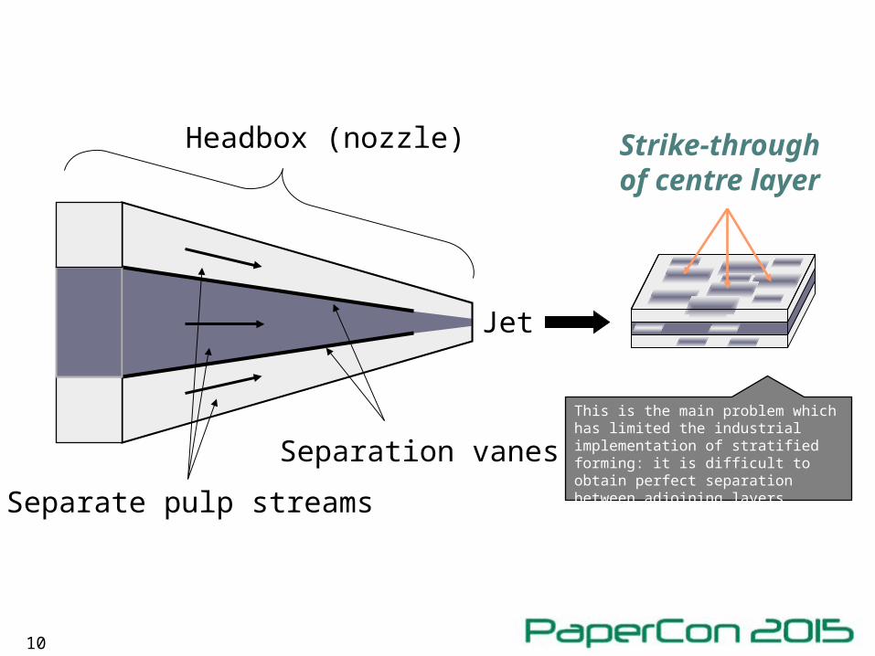
Separation vanes
Strike-through of centre layer
Jet
Separate pulp streams
Headbox (nozzle)
This is the main problem which has limited the industrial implementation of stratified forming: it is difficult to obtain perfect separation between adjoining layers.
11
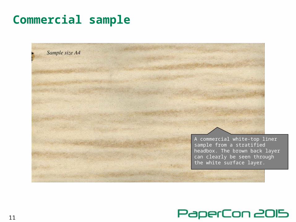
Commercial sample
A commercial white-top liner sample from a stratified headbox. The brown back layer can clearly be seen through the white surface layer.
12
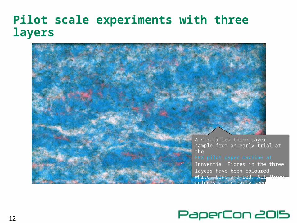
Pilot scale experiments with three layers
A stratified three-layer sample from an early trial at the FEX pilot paper machine at Innventia. Fibres in the three layers have been coloured white, blue and red. All three colours are clearly seen, which implies imperfect stratification.
13
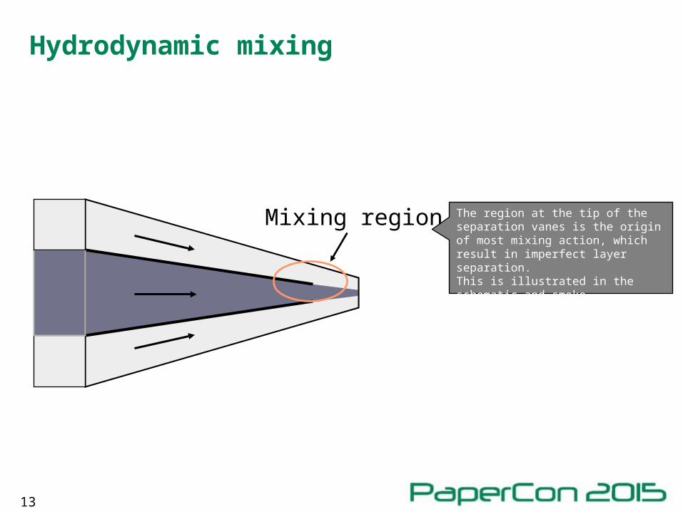
Mixing region
Hydrodynamic mixing
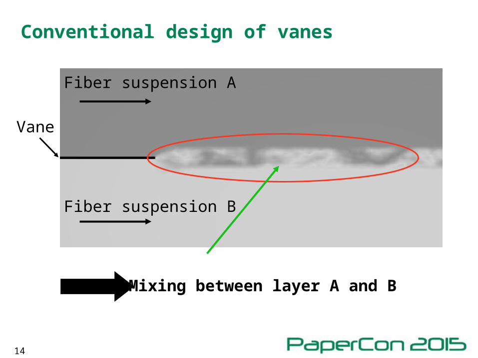
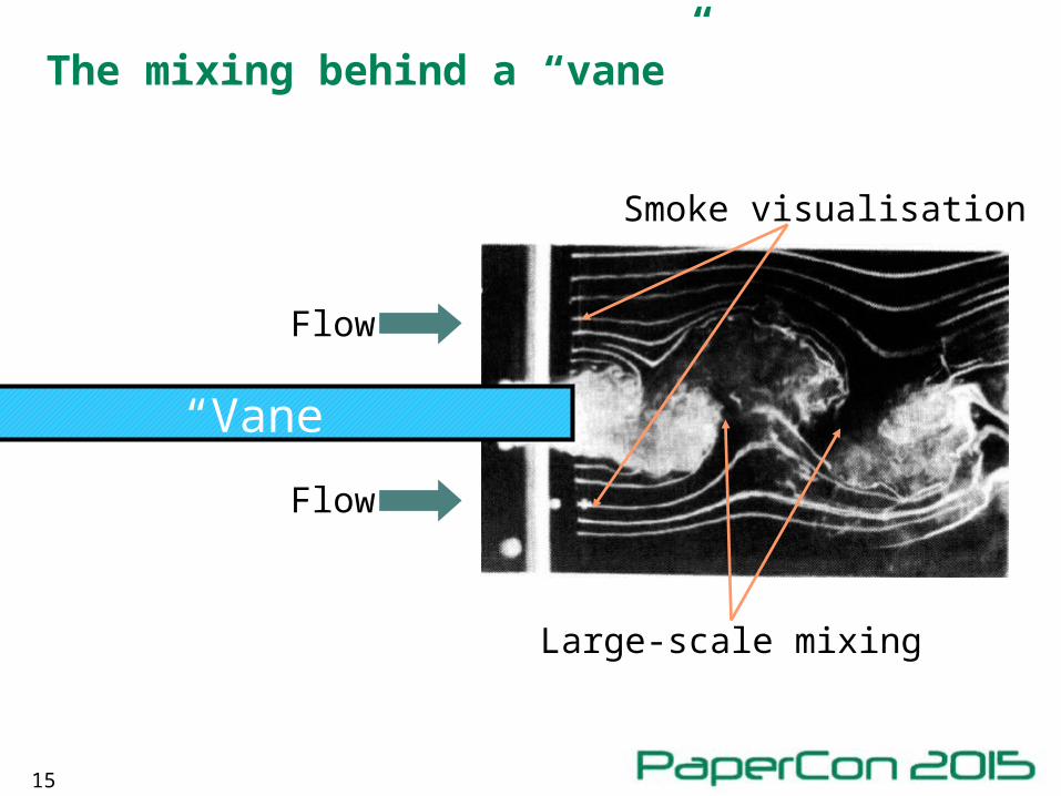
The region at the tip of the separation vanes is the origin of most mixing action, which result in imperfect layer separation.This is illustrated in the schematic and smoke visualization experiments of the next two slides.
14
Conventional design of vanes
Vane
Mixing between layer A and B
Fiber suspension A
Fiber suspension B
15
The mixing behind a “vane”
Flow
Flow
Smoke visualisation
Large-scale mixing
“Vane”
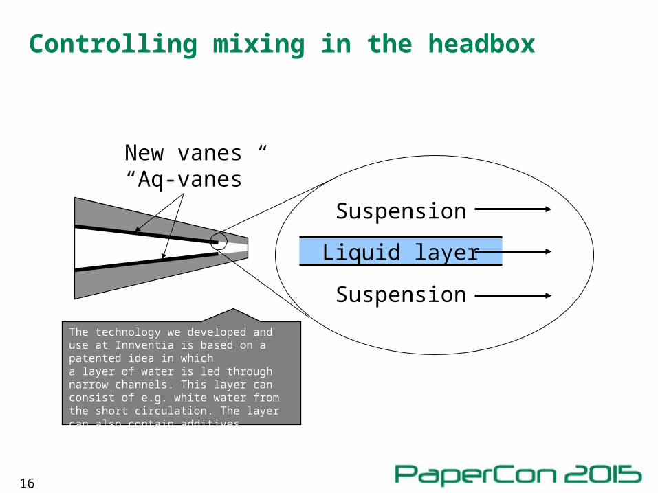
16
Liquid layer
Suspension
Suspension
New vanes“Aq-vanes”
Controlling mixing in the headbox
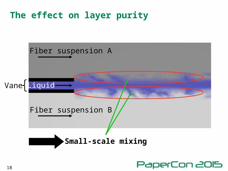
The technology we developed and use at Innventia is based on a patented idea in whicha layer of water is led through narrow channels. This layer can consist of e.g. white water from the short circulation. The layer can also contain additives.
17
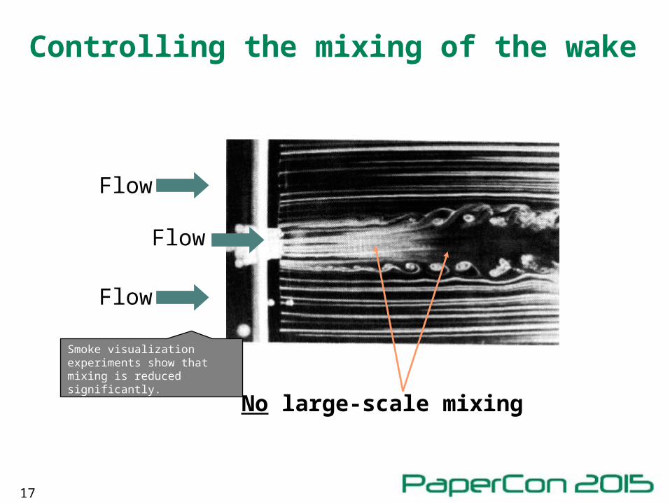
Controlling the mixing of the wake
No large-scale mixing
Flow
Flow
Flow
Smoke visualization experiments show that mixing is reduced significantly.
18
The effect on layer purity
Fiber suspension A
Fiber suspension B
LiquidVane
Small-scale mixing
19
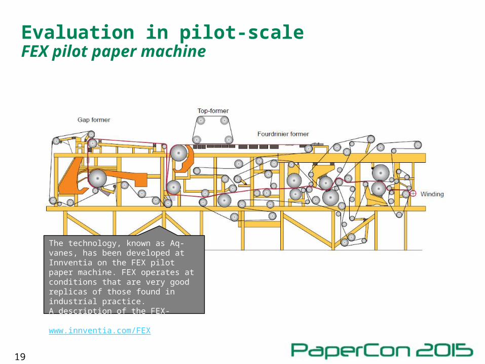
Evaluation in pilot-scaleFEX pilot paper machine
The technology, known as Aq-vanes, has been developed at Innventia on the FEX pilot paper machine. FEX operates at conditions that are very good replicas of those found in industrial practice.A description of the FEX-machine is available at www.innventia.com/FEX
20
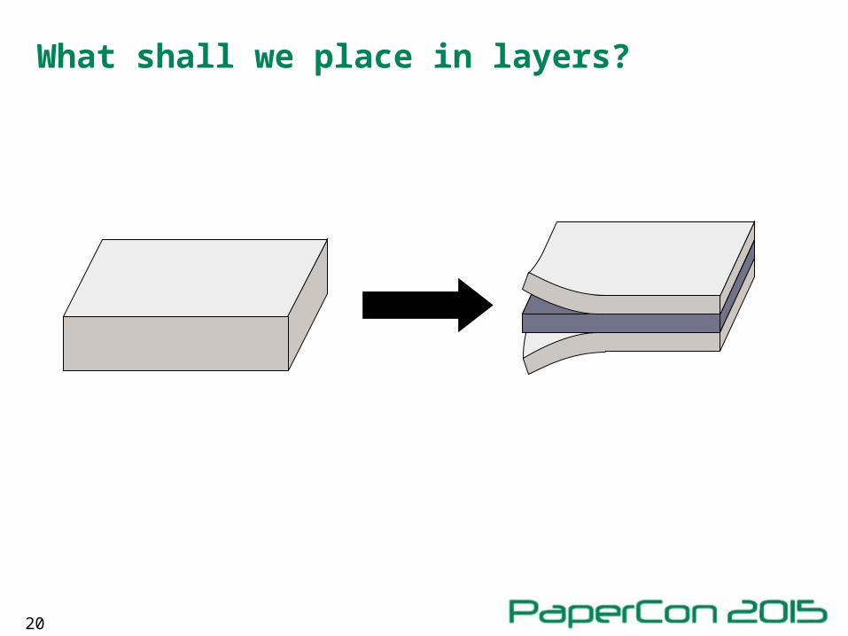
What shall we place in layers?
21
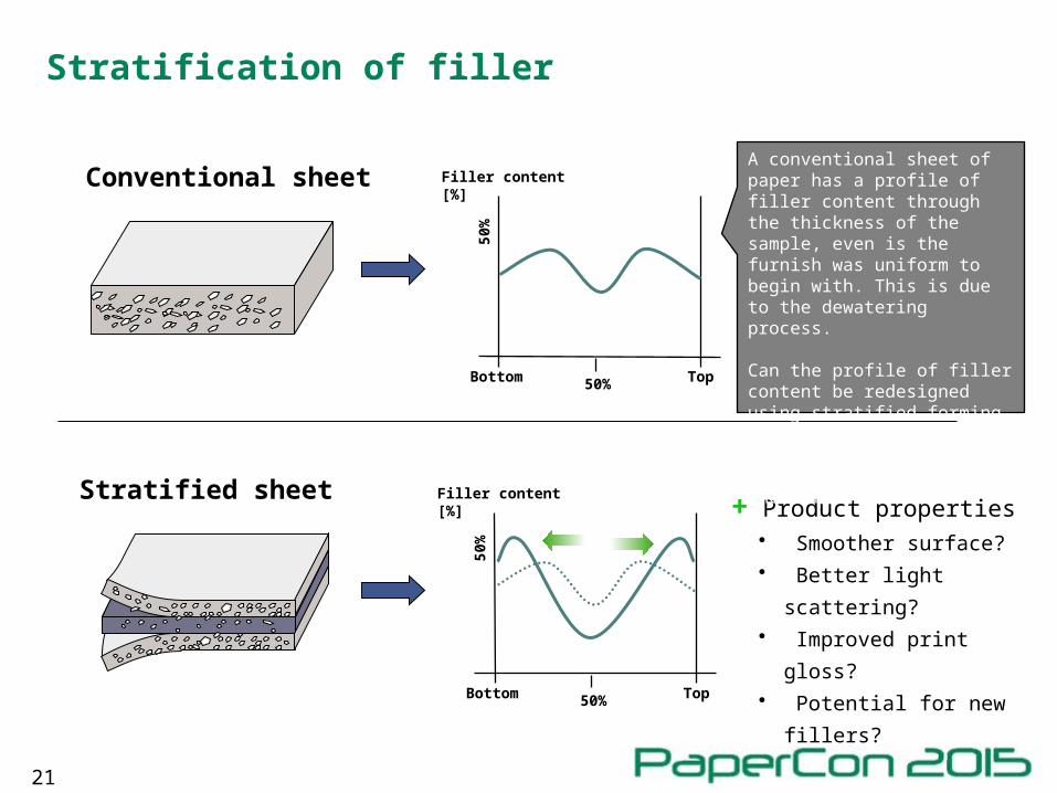
Stratification of filler
Bottom Top50%
Filler content [%]
50%
Bottom Top50%
Filler content [%]50
%Stratified sheet
Conventional sheet
+ Product properties • Smoother surface?• Better light scattering?• Improved print gloss?• Potential for new fillers?
A conventional sheet of paper has a profile of filler content through the thickness of the sample, even is the furnish was uniform to begin with. This is due to the dewatering process.
Can the profile of filler content be redesigned using stratified forming, dosing different amounts of filler in different positions? What would be the effects?
22
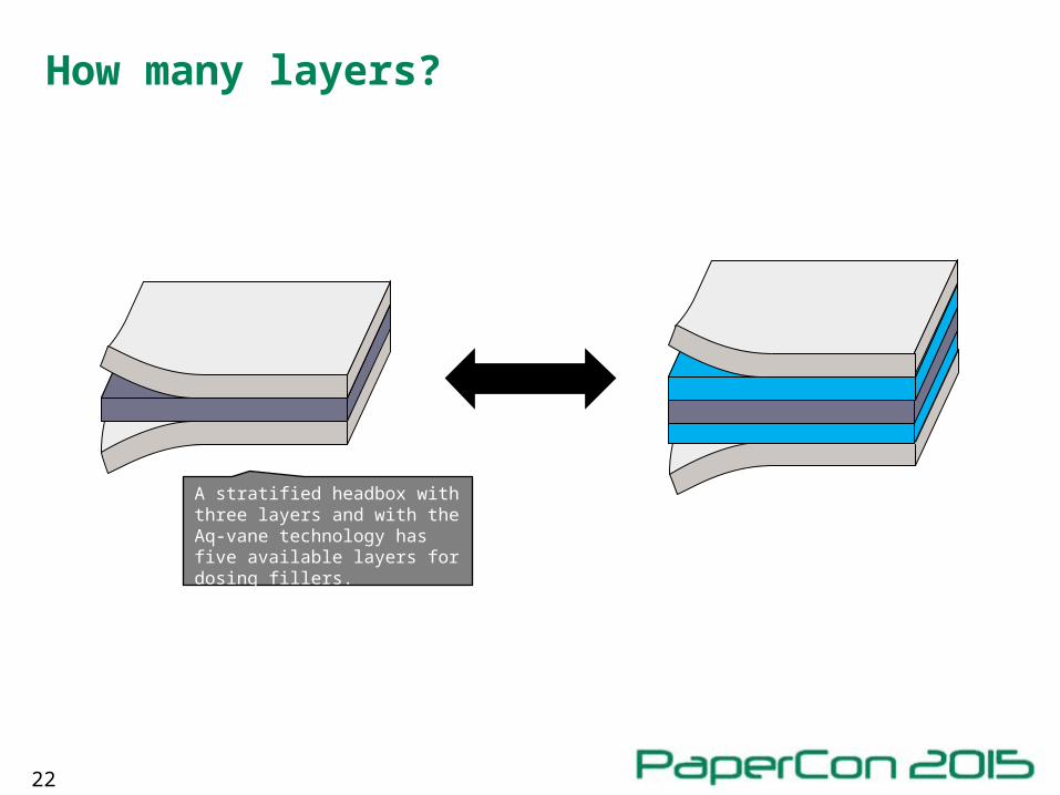
How many layers?
A stratified headbox with three layers and with the Aq-vane technology has five available layers for dosing fillers.
23
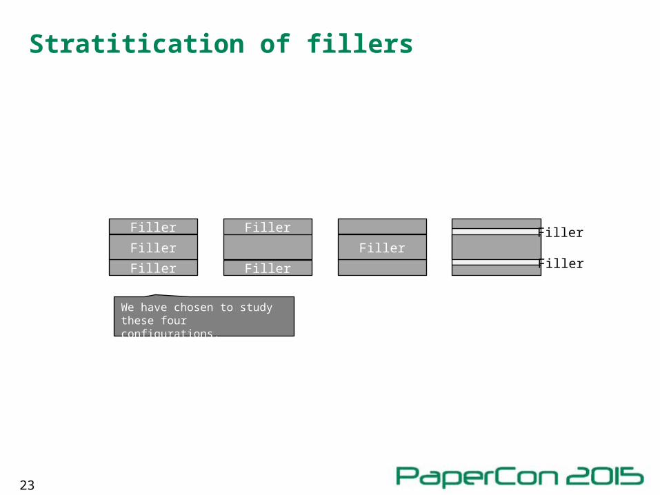
Stratitication of fillers
Filler
Filler
Filler
Filler
Filler
FillerFiller
Filler
We have chosen to study these four configurations.
24
Two demonstration trials
• Stratified dosage of fillers• SC-paper
• 56 g/m2
• 89% mechanical pulp – 11% softwood bleached kraft
• 35% target filler content (Kaolin clay)
• Fine paper• 80 g/m2
• Bleached Eucalypt kraft
• 20% – 30% target filler content (GCC)
25
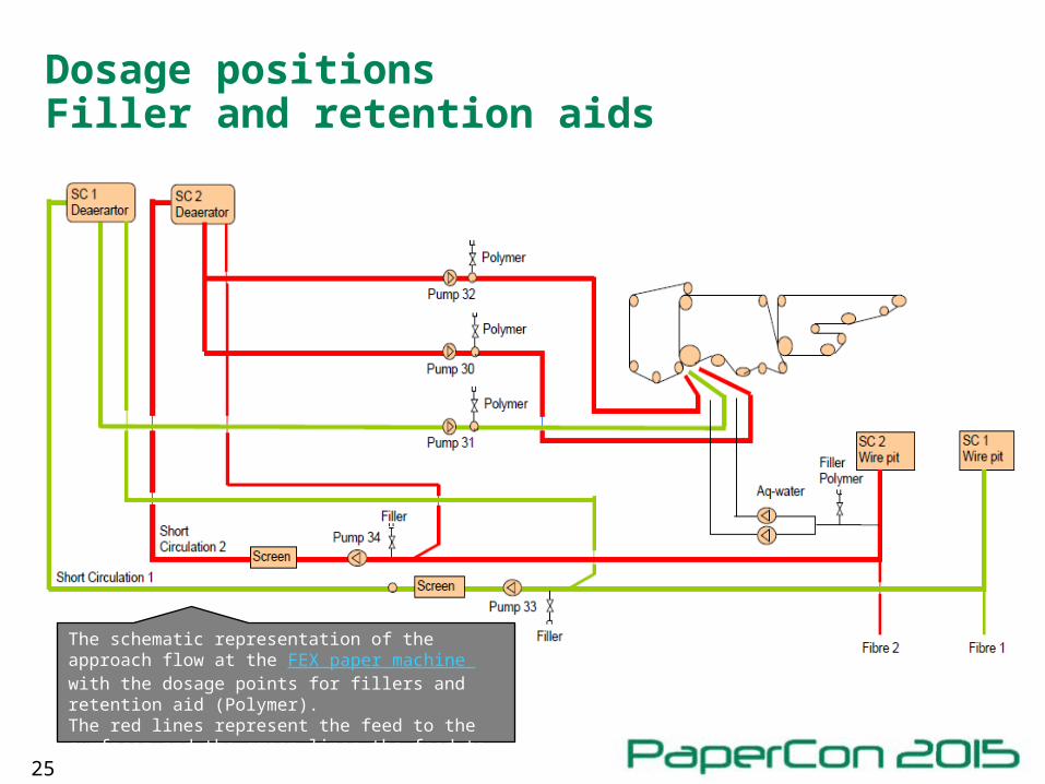
Dosage positionsFiller and retention aids
The schematic representation of the approach flow at the FEX paper machine with the dosage points for fillers and retention aid (Polymer).The red lines represent the feed to the surfaces and the green lines the feed to the bulk.
26
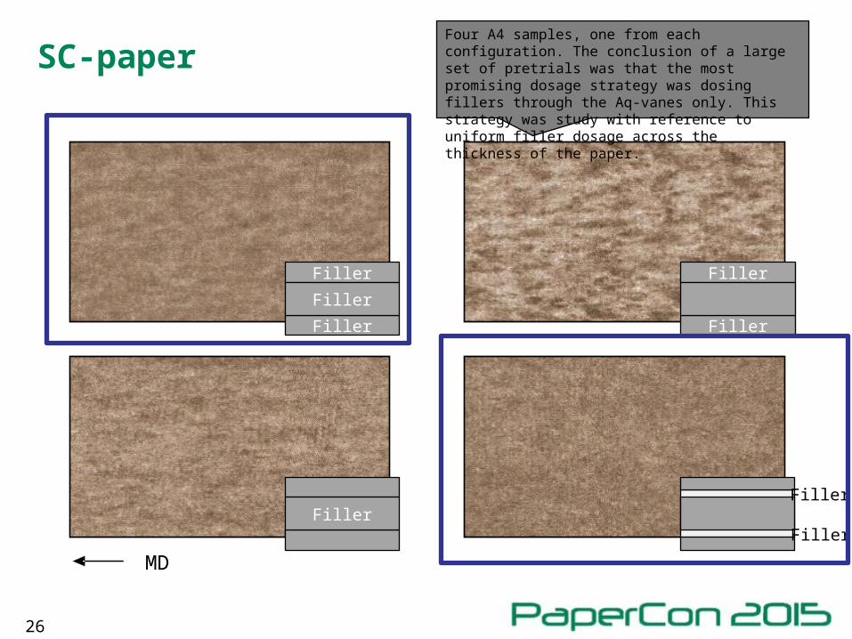
SC-paper
MD
Filler
Filler
Filler
Filler
Filler
Filler
Filler
Filler
Four A4 samples, one from each configuration. The conclusion of a large set of pretrials was that the most promising dosage strategy was dosing fillers through the Aq-vanes only. This strategy was study with reference to uniform filler dosage across the thickness of the paper.
27
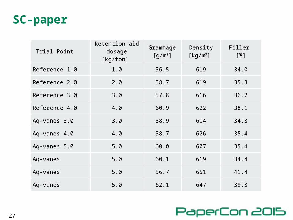
SC-paper
Trial PointRetention aid
dosage [kg/ton] Grammage
[g/m2]Density [kg/m3]
Filler [%]
Reference 1.0 1.0 56.5 619 34.0
Reference 2.0 2.0 58.7 619 35.3
Reference 3.0 3.0 57.8 616 36.2
Reference 4.0 4.0 60.9 622 38.1
Aq-vanes 3.0 3.0 58.9 614 34.3
Aq-vanes 4.0 4.0 58.7 626 35.4
Aq-vanes 5.0 5.0 60.0 607 35.4
Aq-vanes 5.0 60.1 619 34.4
Aq-vanes 5.0 56.7 651 41.4
Aq-vanes 5.0 62.1 647 39.3
28
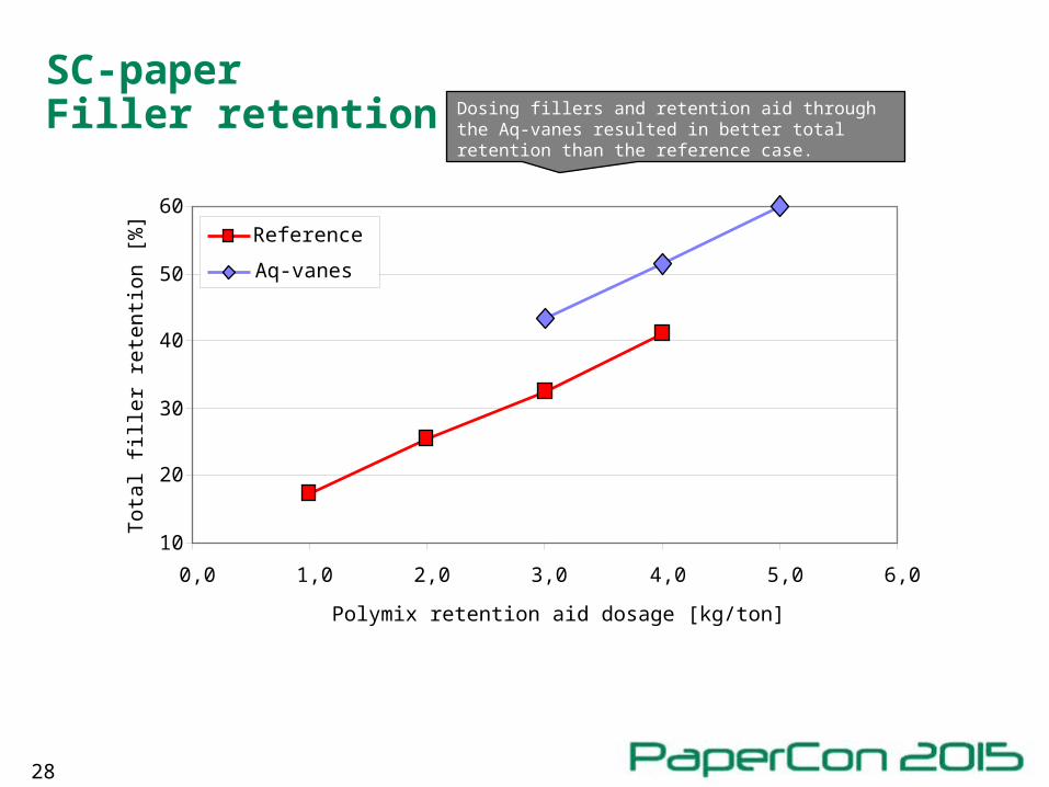
SC-paperFiller retention
10
20
30
40
50
60
0,0 1,0 2,0 3,0 4,0 5,0 6,0
Polymix retention aid dosage [kg/ton]
Tota
l fill
er
rete
ntio
n [%
]
Reference
Aq-vanes
Dosing fillers and retention aid through the Aq-vanes resulted in better total retention than the reference case.
29
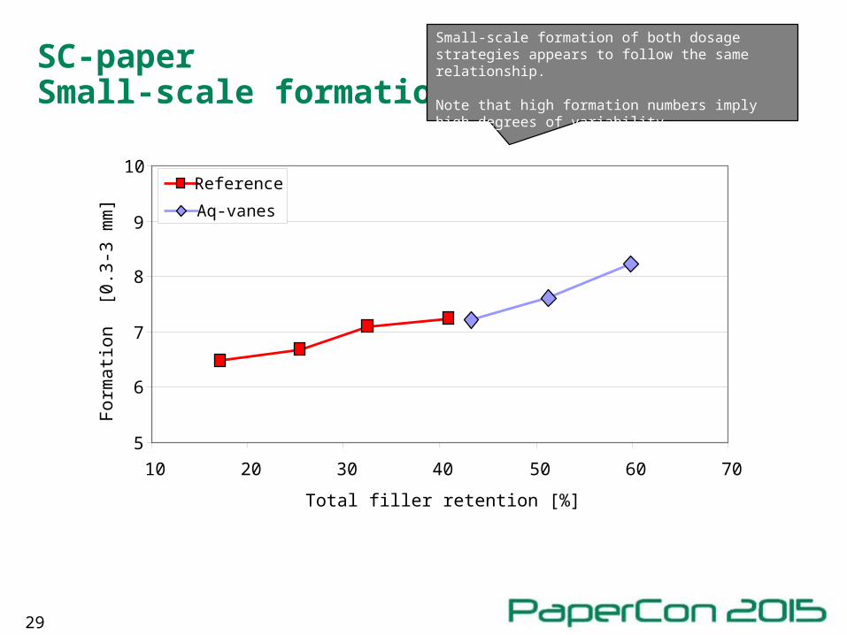
SC-paperSmall-scale formation
5
6
7
8
9
10
10 20 30 40 50 60 70
Total filler retention [%]
Fo
rma
tion
[0
.3-3
mm
]
Reference
Aq-vanes
Small-scale formation of both dosage strategies appears to follow the same relationship.
Note that high formation numbers imply high degrees of variability.
30
SC-paperLarge-scale formation
5
6
7
8
9
10
10 20 30 40 50 60 70
Total filler retention [%]
Fo
rma
tion
[3
-30
mm
]
Reference
Aq-vanes
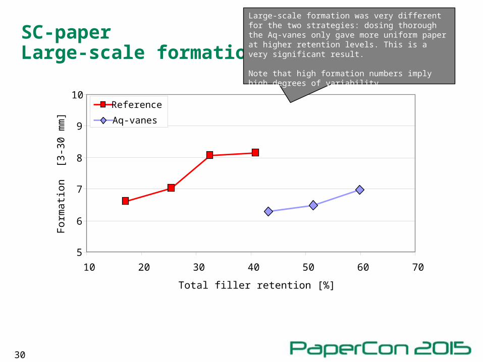
Large-scale formation was very different for the two strategies: dosing thorough the Aq-vanes only gave more uniform paper at higher retention levels. This is a very significant result.
Note that high formation numbers imply high degrees of variability.
31
SC-paperHigher filler content – same tensile index
15
17
19
21
23
25
30 32 34 36 38 40 42 44
Filler [%]
Ten
sile
ind
ex
GE
O [
Nm
/g]
Reference
Aq-vanes
Aq-vanes
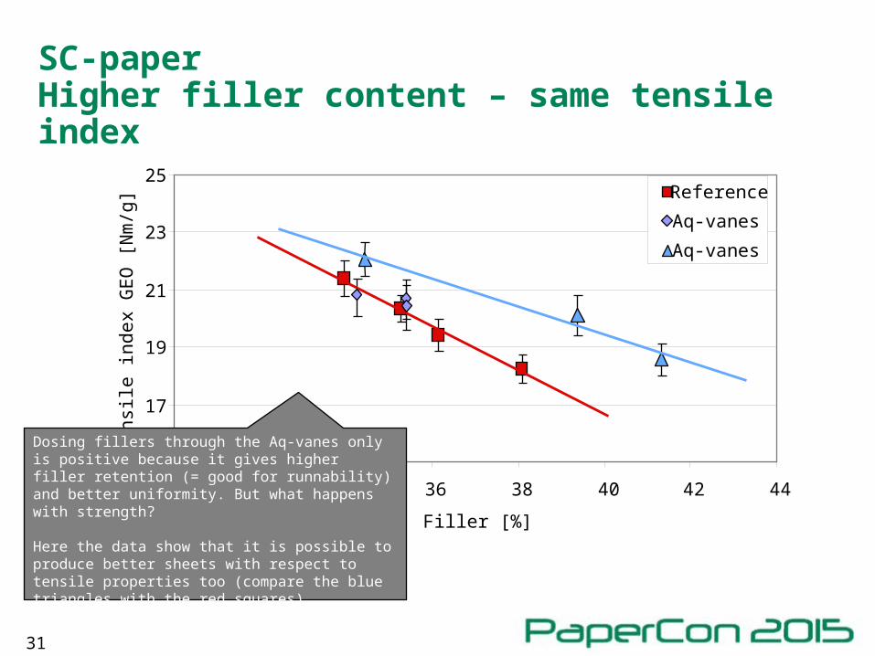
Dosing fillers through the Aq-vanes only is positive because it gives higher filler retention (= good for runnability) and better uniformity. But what happens with strength?
Here the data show that it is possible to produce better sheets with respect to tensile properties too (compare the blue triangles with the red squares).
32
Fine paperTensile index
20
25
30
35
40
45
50Te
ns
ile in
de
x G
M, N
m/g
Filler
Filler
Filler
Filler
Filler
FillerFiller
Filler
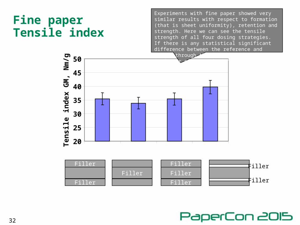
Experiments with fine paper showed very similar results with respect to formation (that is sheet uniformity), retention and strength. Here we can see the tensile strength of all four dosing strategies. If there is any statistical significant difference between the reference and dosing through the Aq-vanes, then it is in favour of stratified forming.
33
Fine paperZ-strength
300
350
400
450
500
550
600Z
-str
eng
th, k
Pa
Filler
Filler
Filler
Filler
Filler
FillerFiller
Filler
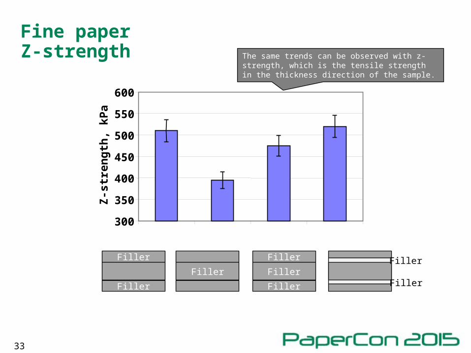
The same trends can be observed with z-strength, which is the tensile strength in the thickness direction of the sample.
34
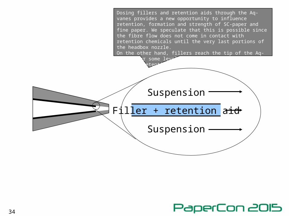
Filler + retention aid
Suspension
Suspension
Dosing fillers and retention aids through the Aq-vanes provides a new opportunity to influence retention, formation and strength of SC-paper and fine paper. We speculate that this is possible since the fibre flow does not come in contact with retention chemicals until the very last portions of the headbox nozzle. On the other hand, fillers reach the tip of the Aq-vane after some level of pre-flocculation, which improves retention.
35
Summary and conclusions
• Pilot-scale demonstration of stratified forming with innovative design of vane technology.
• Stratified dosage of fillers tested for:• SC-paper
• Fine paper
• Dosage of filler and retention aid through the liquid layers gives a wider window of operation (retention-formation).
• Filler content can be increased with no adverse effects on strength and structure.