stratco sanctuary - fencing · it is important to check with your local government authority prior...
TRANSCRIPT
INSTALLATIONGUIDE
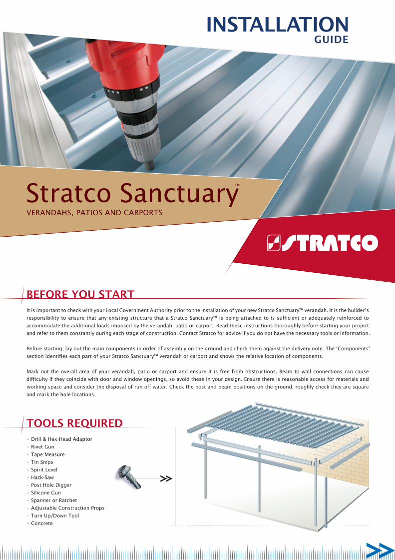
BEFORE YOU START
TOOLS REQUIRED• Drill & Hex-Head Adaptor
• Rivet Gun
• Tape Measure
• Tin Snips
• Spirit Level
• Hack-Saw
• Post Hole Digger
• Silicone Gun
• Spanner or Ratchet
• Adjustable Construction Props
• Turn Up/Down Tool
• Concrete
It is important to check with your Local Government Authority prior to the installation of your new Stratco Sanctuary™ verandah. It is the builder’s
responsibility to ensure that any existing structure that a Stratco Sanctuary™ is being attached to is sufficient or adequately reinforced to
accommodate the additional loads imposed by the verandah, patio or carport. Read these instructions thoroughly before starting your project
and refer to them constantly during each stage of construction. Contact Stratco for advice if you do not have the necessary tools or information.
Before starting, lay out the main components in order of assembly on the ground and check them against the delivery note. The ‘Components’
section identifies each part of your Stratco Sanctuary™ verandah or carport and shows the relative location of components.
Mark out the overall area of your verandah, patio or carport and ensure it is free from obstructions. Beam to wall connections can cause
difficulty if they coincide with door and window openings, so avoid these in your design. Ensure there is reasonable access for materials and
working space and consider the disposal of run off water. Check the post and beam positions on the ground, roughly check they are square
and mark the hole locations.
Stratco SanctuaryVeRAnDAHS, PATIoS AnD CARPoRTS
™
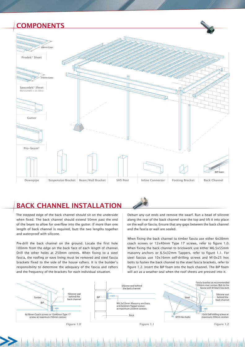
650mm Cover
415mm Cover
BIP foam
Footing BracketInline ConnectorSHS PostBeam/Wall BracketSuspension BracketDownpipe
Pro-beam®
Gutter
Prodek® Sheet
Spacedek® Sheet(Not available in all states)
Back Channel
M6.5x55mm Masonry anchorsor 6.5x32mm Tapper screwsat maximum 250mm centres
Silicone seal behindthe back channel
Brick
BIP
6x38mm Coach screws or 12x40mm Type 17screws at maximum 250mm centres
Silicone sealbehind the
back channel
BIP
Timber SteelSilicone sealbehind the
back channel
Fascia bracket at recommended1200mm max centres. Bolt to the
fascia with M10x25 hex bolt.
10x16 Self-drilling screws atmaximum 250mm centresM10 Hex bolts
The stepped edge of the back channel should sit on the underside
when fixed. The back channel should extend 50mm past the end
of the beam to allow for overflow into the gutter. If more than one
length of back channel is required, butt the two lengths together
and waterproof with silicone.
Pre-drill the back channel on the ground. Locate the first hole
100mm from the edge on the back face of each length of channel.
Drill the other holes at 250mm centres. When fixing to a steel
fascia, the roofing or eave lining must be removed and steel fascia
brackets fixed to the side of the house rafters. It is the builder’s
responsibility to determine the adequacy of the fascia and rafters
and the frequency of the brackets for each individual situation.
COMPONENTS
BACK CHANNEL INSTALLATIONDeburr any cut ends and remove the swarf. Run a bead of silicone
along the rear of the back channel near the top and lift it into place
on the wall or fascia. Ensure that any gaps between the back channel
and the fascia or wall are sealed.
When fixing the back channel to timber fascia use either 6x38mm
coach screws or 12x40mm Type 17 screws, refer to figure 1.0.
When fixing the back channel to brickwork use either M6.5x55mm
masonry anchors or 6.5x32mm Tappers, refer to figure 1.1. For
steel fascias use 10x16mm self-drilling screws and M10x25 hex
bolts to fasten the back channel to the steel fascia brackets, refer to
figure 1.2. Insert the BIP foam into the back channel. The BIP foam
will act as a weather seal when the roof sheets are pressed into it.
Figure 1.2Figure 1.1Figure 1.0
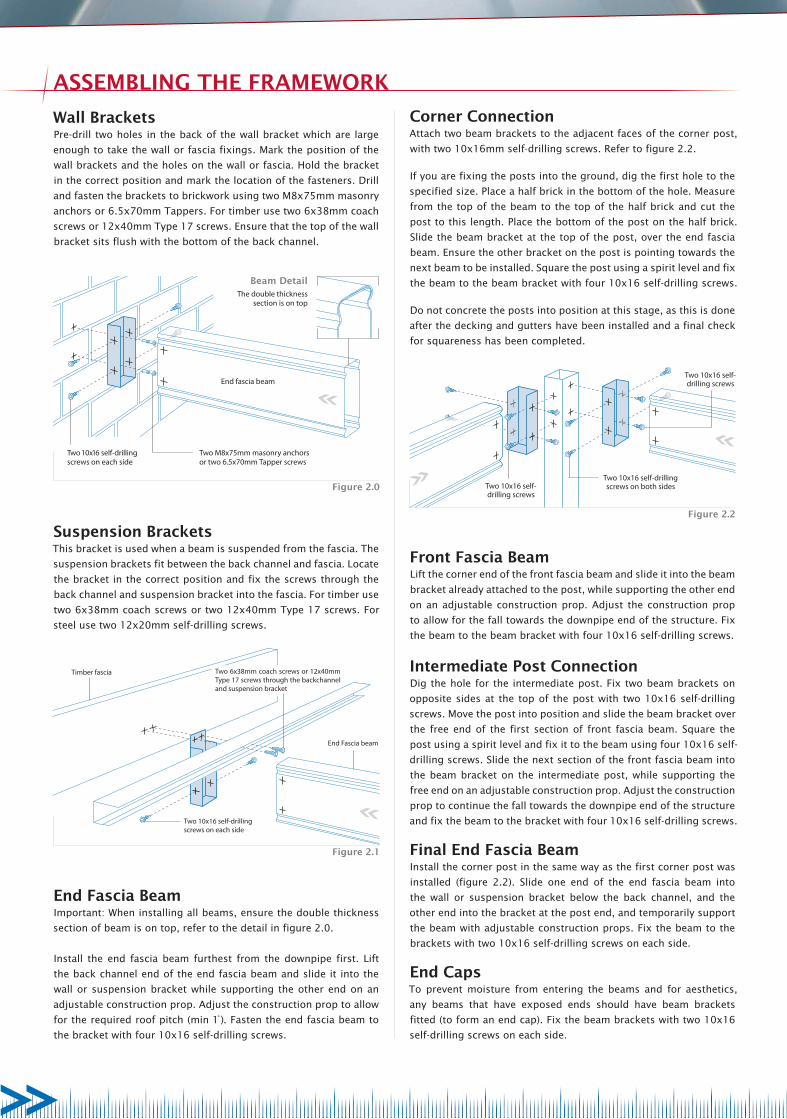
Two 10x16 self-drillingscrews on each side
End Fascia beam
Timber fascia Two 6x38mm coach screws or 12x40mm Type 17 screws through the backchannel and suspension bracket
Two 10x16 self-drilling screws
Two 10x16 self-drillingscrews on both sidesTwo 10x16 self-
drilling screws
The double thicknesssection is on top
Beam Detail
Two 10x16 self-drillingscrews on each side
Two M8x75mm masonry anchorsor two 6.5x70mm Tapper screws
End fascia beam
Wall BracketsPre-drill two holes in the back of the wall bracket which are large
enough to take the wall or fascia fixings. Mark the position of the
wall brackets and the holes on the wall or fascia. Hold the bracket
in the correct position and mark the location of the fasteners. Drill
and fasten the brackets to brickwork using two M8x75mm masonry
anchors or 6.5x70mm Tappers. For timber use two 6x38mm coach
screws or 12x40mm Type 17 screws. Ensure that the top of the wall
bracket sits flush with the bottom of the back channel.
Suspension BracketsThis bracket is used when a beam is suspended from the fascia. The
suspension brackets fit between the back channel and fascia. Locate
the bracket in the correct position and fix the screws through the
back channel and suspension bracket into the fascia. For timber use
two 6x38mm coach screws or two 12x40mm Type 17 screws. For
steel use two 12x20mm self-drilling screws.
End Fascia BeamImportant: When installing all beams, ensure the double thickness
section of beam is on top, refer to the detail in figure 2.0.
Install the end fascia beam furthest from the downpipe first. Lift
the back channel end of the end fascia beam and slide it into the
wall or suspension bracket while supporting the other end on an
adjustable construction prop. Adjust the construction prop to allow
for the required roof pitch (min 1̊ ). Fasten the end fascia beam to
the bracket with four 10x16 self-drilling screws.
Corner ConnectionAttach two beam brackets to the adjacent faces of the corner post,
with two 10x16mm self-drilling screws. Refer to figure 2.2.
If you are fixing the posts into the ground, dig the first hole to the
specified size. Place a half brick in the bottom of the hole. Measure
from the top of the beam to the top of the half brick and cut the
post to this length. Place the bottom of the post on the half brick.
Slide the beam bracket at the top of the post, over the end fascia
beam. Ensure the other bracket on the post is pointing towards the
next beam to be installed. Square the post using a spirit level and fix
the beam to the beam bracket with four 10x16 self-drilling screws.
Do not concrete the posts into position at this stage, as this is done
after the decking and gutters have been installed and a final check
for squareness has been completed.
Figure 2.1
Front Fascia BeamLift the corner end of the front fascia beam and slide it into the beam
bracket already attached to the post, while supporting the other end
on an adjustable construction prop. Adjust the construction prop
to allow for the fall towards the downpipe end of the structure. Fix
the beam to the beam bracket with four 10x16 self-drilling screws.
Intermediate Post ConnectionDig the hole for the intermediate post. Fix two beam brackets on
opposite sides at the top of the post with two 10x16 self-drilling
screws. Move the post into position and slide the beam bracket over
the free end of the first section of front fascia beam. Square the
post using a spirit level and fix it to the beam using four 10x16 self-
drilling screws. Slide the next section of the front fascia beam into
the beam bracket on the intermediate post, while supporting the
free end on an adjustable construction prop. Adjust the construction
prop to continue the fall towards the downpipe end of the structure
and fix the beam to the bracket with four 10x16 self-drilling screws.
Final End Fascia BeamInstall the corner post in the same way as the first corner post was
installed (figure 2.2). Slide one end of the end fascia beam into
the wall or suspension bracket below the back channel, and the
other end into the bracket at the post end, and temporarily support
the beam with adjustable construction props. Fix the beam to the
brackets with two 10x16 self-drilling screws on each side.
End CapsTo prevent moisture from entering the beams and for aesthetics,
any beams that have exposed ends should have beam brackets
fitted (to form an end cap). Fix the beam brackets with two 10x16
self-drilling screws on each side.
Figure 2.2
ASSEMBLING THE FRAMEWORK
Figure 2.0
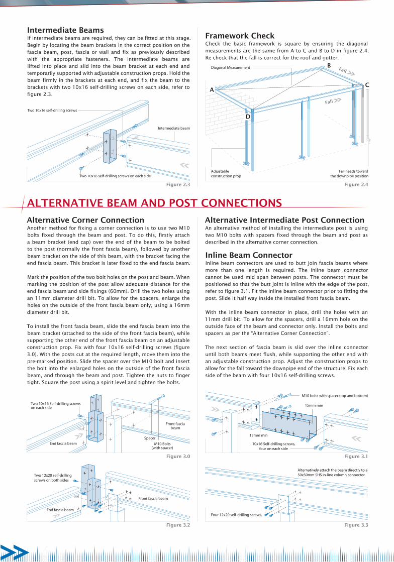
Intermediate beam
Two 10x16 self-drilling screws on each side
Two 10x16 self-drilling screws
A
D
B
C
Fall
Fall
Adjustableconstruction prop
Fall heads towardthe downpipe position
Diagonal Measurement
Two 12x20 self-drillingscrews on both sides
End fascia beam
Front fascia beam
Four 12x20 self-drilling screws.
Alternatively attach the beam directly to a50x50mm SHS in-line column connector.
Alternative Corner ConnectionAnother method for fixing a corner connection is to use two M10 bolts fixed through the beam and post. To do this, firstly attach a beam bracket (end cap) over the end of the beam to be bolted to the post (normally the front fascia beam), followed by another beam bracket on the side of this beam, with the bracket facing the end fascia beam. This bracket is later fixed to the end fascia beam.
Mark the position of the two bolt holes on the post and beam. When marking the position of the post allow adequate distance for the end fascia beam and side fixings (60mm). Drill the two holes using an 11mm diameter drill bit. To allow for the spacers, enlarge the holes on the outside of the front fascia beam only, using a 16mm diameter drill bit.
To install the front fascia beam, slide the end fascia beam into the beam bracket (attached to the side of the front fascia beam), while supporting the other end of the front fascia beam on an adjustable construction prop. Fix with four 10x16 self-drilling screws (figure 3.0). With the posts cut at the required length, move them into the pre-marked position. Slide the spacer over the M10 bolt and insert the bolt into the enlarged holes on the outside of the front fascia beam, and through the beam and post. Tighten the nuts to finger tight. Square the post using a spirit level and tighten the bolts.
Alternative Intermediate Post ConnectionAn alternative method of installing the intermediate post is using two M10 bolts with spacers fixed through the beam and post as described in the alternative corner connection.
Inline Beam ConnectorInline beam connectors are used to butt join fascia beams where more than one length is required. The inline beam connector cannot be used mid span between posts. The connector must be positioned so that the butt joint is inline with the edge of the post, refer to figure 3.1. Fit the inline beam connector prior to fitting the post. Slide it half way inside the installed front fascia beam.
With the inline beam connector in place, drill the holes with an 11mm drill bit. To allow for the spacers, drill a 16mm hole on the outside face of the beam and connector only. Install the bolts and spacers as per the “Alternative Corner Connection”.
The next section of fascia beam is slid over the inline connector until both beams meet flush, while supporting the other end with an adjustable construction prop. Adjust the construction props to allow for the fall toward the downpipe end of the structure. Fix each side of the beam with four 10x16 self-drilling screws.
Intermediate BeamsIf intermediate beams are required, they can be fitted at this stage. Begin by locating the beam brackets in the correct position on the fascia beam, post, fascia or wall and fix as previously described with the appropriate fasteners. The intermediate beams are lifted into place and slid into the beam bracket at each end and temporarily supported with adjustable construction props. Hold the beam firmly in the brackets at each end, and fix the beam to the brackets with two 10x16 self-drilling screws on each side, refer to figure 2.3.
Framework CheckCheck the basic framework is square by ensuring the diagonal measurements are the same from A to C and B to D in figure 2.4. Re-check that the fall is correct for the roof and gutter.
Figure 2.3
Figure 3.2
Two 10x16 Self-drilling screwson each side
M10 Bolts(with spacer)
Spacer
Front fascia beam
End fascia beam
Figure 3.0
Figure 2.4
Figure 3.3
M10 bolts with spacer (top and bottom)
10x16 Self-drilling screws,four on each side
15mm min
15mm min
Figure 3.1
ALTERNATIvE BEAM AND POST CONNECTIONS

Section of Prodek® showing the position of the fixings in the above diagrams
BIP foam
Rivet from undersidetwo rivets per pan
Back channel
BACK CHANNELFIXING
Two hex head self-drilling screws perpan at each support.
BEAM FIXING
Section of Spacedek®showing the positionof the fixings
Roof DeckingWhile still at ground level, the ends of the decking need to be
turned up or down approximately 30 degrees using a turn up/down
tool. Turn the ends of the decking up at the back channel end and
down at the gutter end.
Decking should be positioned to allow a 50mm overhang into all of
the gutters and should be laid with the overlapping rib away from
the prevailing wind. Ensure that all of the sheet overlaps are facing
the same direction. Mark the back channel and front fascia beam
every 1000mm to check that the decking is laid square.
Begin installing the first sheet of decking. Lift the first sheet into
place and slide it firmly into the BIP foam in the back channel to
guarantee the correct weather proofing. Check the sheet is square
against the back channel and side fascia beam. At the back channel
end, rivet the decking from underneath through the raised edge
of the bottom of the back channel, using two 3mm rivets per pan.
Weatherproof with silicone. At each supporting beam fasten down
the sheet from above using two 10x16 self-drilling screws per pan.
Remove any swarf.
Lay each sheet of decking over the sidelap of the previous sheet
and slide the decking firmly into the BIP foam. Fasten as previously
described and remove any swarf.
For Prodek® spans between 2800 and 3900mm, one 4.8mm rivet is
required mid-span of the lap. For Prodek® spans between 3900 and
4500mm, two 4.8mm rivets are required evenly spaced along the
lap. All rivets are to be weather proofed with silicone.
Fibreglass SheetingWhere extra natural light is required, fibreglass sheets can be used.
Fibreglass sheets must be installed with both sides overlapping the
ribs of the adjoining metal decking. To maintain the strength of
the roof a minimum of two metal sheets are required either side of
each fibreglass sheet.
Place the side crest of the roof light over the metal decking and
slide the roof light firmly into the BIP foam in the back channel. Drill
4.5mm holes through the raised edge of the bottom of the back
channel at the rate of two per pan. Fasten with split tail soft pull
rivets and weatherproof with silicone.
Pre-drill 7mm holes through the roof light at each supporting beam
to allow for expansion. Fasten the roof light using 10x16 self-
drilling screws and 20mm weatherseal washers at the rate of two
fasteners per pan. Remove any swarf.
Place the following metal sheet under the crest of the roof light, and
when correctly nested, slide the metal decking firmly into the BIP
foam in the back channel. Fix in the manner previously described
for metal decking.
To prevent ponding, the roof lights are to be supported every
1200mm with either 3mm steel strapping or Stratco ceiling batten.
The strap or ceiling batten must be fastened to at least the first two
ribs of the metal decking on either side of the roof light.Figure 4.0
GUTTERS
ROOFING
Preparing the GuttersWhen establishing the length of the gutters allow for the mitre cuts
and ‘tags’. The back face of the front gutter should be the same
length as the front fascia beam. The back face of the side gutters
should be the same length as the roof decking, less 50mm. Where
more than one length of gutter is needed along a straight run, allow
for an additional 100mm at the overlap. Cut the gutters to the
correct measurements. An option for cutting mitres is described in
the Stratco ‘DIY Gutter and Downpipe’ brochure.
Attach the stop ends to the side gutters using 3mm rivets, remove
any swarf and weatherproof with silicone. Determine the position
of the downpipe (this should be in line with a post) and cut a hole
in the base of the gutter. Insert the gutter outlet from the inside of
the gutter and rivet the outlet in place using 3mm rivets, remove
any swarf and weatherproof with silicone.
Installing the GuttersTemporarily fix the front gutter to the roof decking using clamps
at 300mm centres. Adjust the position of the gutter to ensure that
the roof decking overhangs 50mm into the gutter. Rivet through
the bottom of the decking and back lip of the gutter at maximum
900mm centres, using 3mm rivets.
POSTS
M12 Hex bolt Footing bracket
80mm minimum
80mm minimum
M12x75mm Masonry anchor or 12 x 100mm Screwbolt
120mm minimum with reinforcement mesh
Post embedded aminimum of 450mm
into the concrete
Depth as specified
Corbel as specified
Using clamps as previously described, temporarily attach the side gutter to the roof
decking. Join the front and side gutters at the corner, to form a mitre join ensure that the
‘tags’ from one gutter fit neatly into the mitre cut of the other, and clamp together. Adjust
the side gutter to make sure that it runs parallel to the roof decking and rivet the two
gutters together through the front face, bottom and back face using 3mm rivets.
Rivet through the bottom of the deck and the back lip of the side gutter at maximum
900mm centres using 3mm rivets. Make sure that the gutters and roof are totally free
from swarf and silicone seal the mitre joints and any exposed rivets. You may need to
temporarily unscrew the self-drilling screws at the corner and lift the decking to be able
to properly seal the mitre joints. Once the mitres have been sealed re-tighten the self-
drilling screws. Repeat this procedure for the side gutter at the other end.
Gutter BracketsTo install the Universal Deck Strap, roll the curved end into the bead of the gutter and pull
it down onto the crest of the decking. Ensure that the front face of the gutter is straight
and drill a hole through the bracket and decking. Fix the bracket to the deck using a 3mm
rivet. Remove any swarf and weatherproof with silicone.
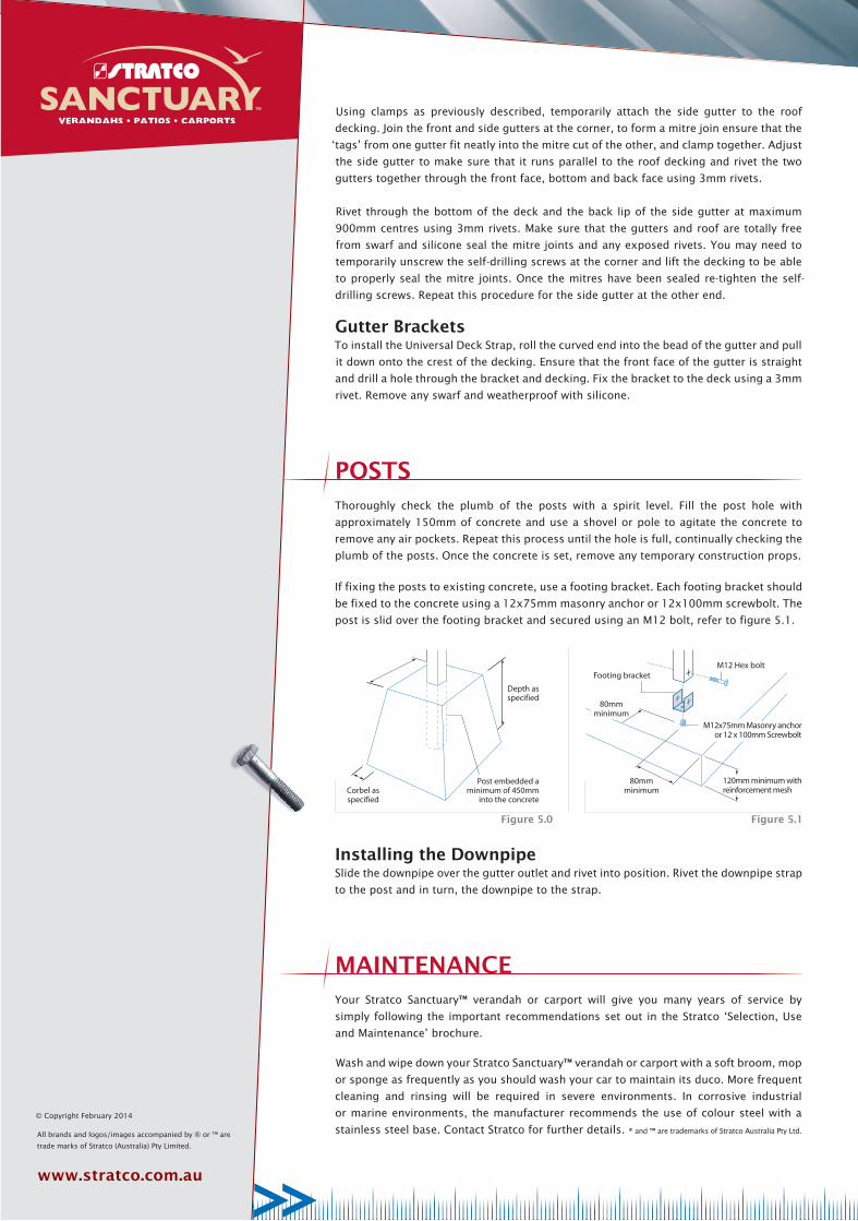
Thoroughly check the plumb of the posts with a spirit level. Fill the post hole with
approximately 150mm of concrete and use a shovel or pole to agitate the concrete to
remove any air pockets. Repeat this process until the hole is full, continually checking the
plumb of the posts. Once the concrete is set, remove any temporary construction props.
If fixing the posts to existing concrete, use a footing bracket. Each footing bracket should
be fixed to the concrete using a 12x75mm masonry anchor or 12x100mm screwbolt. The
post is slid over the footing bracket and secured using an M12 bolt, refer to figure 5.1.
Your Stratco Sanctuary™ verandah or carport will give you many years of service by
simply following the important recommendations set out in the Stratco ‘Selection, Use
and Maintenance’ brochure.
Wash and wipe down your Stratco Sanctuary™ verandah or carport with a soft broom, mop
or sponge as frequently as you should wash your car to maintain its duco. More frequent
cleaning and rinsing will be required in severe environments. In corrosive industrial
or marine environments, the manufacturer recommends the use of colour steel with a
stainless steel base. Contact Stratco for further details. ® and ™ are trademarks of Stratco Australia Pty Ltd.
MAINTENANCE
Figure 5.1Figure 5.0
Installing the DownpipeSlide the downpipe over the gutter outlet and rivet into position. Rivet the downpipe strap
to the post and in turn, the downpipe to the strap.
© Copyright February 2014