strand lighting - dallas strand lighting - asia limited · light pack light pack installation &...
TRANSCRIPT

The material in this manual is for information purposes only and is subject to change without notice.Strand Lighting assumes no responsibility for any errors or omissions which may appear in this manual.For comments and suggestions regarding corrections and/or updates to this manual, please contact yournearest Strand Lighting office.El contenido de este manual es solamente para información y está sujeto a cambios sin previo aviso.Strand Lighting no asume responsabilidad por errores o omisiones que puedan aparecer. Cualquiercomentario, sugerencia o corrección con respecto a este manual, favor de dirijirlo a la oficina de StrandLighting más cercana.Der Inhalt dieses Handbuches ist nur für Informationszwecke gedacht, Aenderungen sind vorbehalten.Strand Lighting uebernimmt keine Verantwortung für Fehler oder Irrtuemer, die in diesem Handbuchauftreten. Für Bemerkungen und Verbesserungsvorschlaege oder Vorschlaege in Bezug auf Korrekturenund/oder Aktualisierungen in diesem Handbuch, moechten wir Sie bitten, Kontakt mit der naechstenStrand Lighting-Niederlassung aufzunehmen.Le matériel décrit dans ce manuel est pour information seulement et est sujet à changements sans préavis.La compagnie Strand Lighting n'assume aucune responsibilité sur toute erreur ou ommission inscrite dansce manuel. Pour tous commentaires ou suggestions concernant des corrections et/ou les mises à jour de cemanuel, veuillez s'll vous plait contacter le bureau de Strand Lighting le plus proche.Information contained in this document may not be duplicated in full or in part by any person withoutprior written approval of Strand Lighting. Its sole purpose is to provide the user with conceptualinformation on the equipment mentioned. The use of this document for all other purposes is specificallyprohibited. Certain features of the equipment described in this document may form the subject of patentsor patent applications.
Document Number: 2-450188-010Version as of: August 31, 2010
Light Pack Light Pack Installation & Operation Guide©2010 Philips Group. All rights reserved.
Strand Lighting - Dallas10911 Petal StreetDallas, TX 75238Tel: 214-647-7880Fax: 214-647-8031
Strand Lighting - New York267 5th Ave, 4th FloorNew York, NY 10016
Tel: 212-213-8219Fax: 212-532-2593
Strand Lighting - Asia LimitedRoom 6-10, 20/F Delta House 3 On Yiu Street
Shatin, N.T. Hong KongTel: + 852 2757 3033Fax: + 852 2757 1767
Strand Selecon - Auckland19-21 Kawana Street
Northcote, Auckland 0627New Zealand
Tel: +64 9 481 0100Fax: +64 9 481 0101
Strand Lighting - EuropeMarssteden 152
Enschede 7547 TDThe Netherlands
Tel: +31 53 4500424Fax: +31 53 4500425
Website:www.strandlighting.com

Light Pack 120v Dimming Module Installation & Operation Guide
Important Safeguards
When using electrical equipment, basic safety precautions should always be followed including the following:
a. READ AND FOLLOW ALL SAFETY INSTRUCTIONS.b. Do not use outdoors.c. Do not mount near gas or electric heaters.d. Equipment should be mounted in locations and at heights where it will not
readily be subjected to tampering by unauthorized personnel.e. The use of accessory equipment not recommended by the manufacturer
may cause an unsafe condition.f. Do not use this equipment for other than intended use.g. Refer service to qualified personnel.
SAVE THESE INSTRUCTIONS.
WARNING: You must have access to a main circuit breaker or other power disconnect device before installing any wiring. Be sure that power is disconnected by removing fuses or turning the main circuit breaker off before installation. Installing the device with power on may expose you to dangerous voltage and damage the device. A qualified electrician must perform this installation.
WARNING: Refer to National Electrical Code® and local codes for cable specifications. Failure to use proper cable can result in damage to equipment or danger to persons.
WARNING: To reduce the risk of fire or shock hazard, do not expose this equipment to rain or moisture.
1
Installation & Operation Guide Light Pack 120v Dimming Module
TABLE OF CONTENTS
Preface .......................................................................................................................................3About this Guide ............................................................................................................... 3
About the Light Pack Dimming Module ...................................................................................4
Installation .................................................................................................................................5Yoke Mount (Strand #71340) .......................................................................................... 5Wall Mount (Strand #71341) ........................................................................................... 5Pipe Mount (Strand #71342) ............................................................................................ 5
Connecting Power .....................................................................................................................6
Connecting Data ........................................................................................................................6
Setting Mode and Address ........................................................................................................7
Effects .......................................................................................................................................8Intelligent Effects Network............................................................................................... 8
Operation ...................................................................................................................................9
Specifications ..........................................................................................................................10
Catalog Number Reference .....................................................................................................11Light Pack 120v Modules ............................................................................................... 11
2

Light Pack 120v Dimming Module Installation & Operation Guide
PREFACE
About this Guide
The document provides installation and operation instructions for the following products:• Light Pack 120v Dimming Module - 750 watt• Light Pack 120v Dimming Module - 1200 watt
Please read all instructions before installing or using this product. Retain this guide for future reference.
IMPORTANT INFORMATION. PLEASE READ!
This unit is intended for installation in accordance with the National Electric Code® and local regulations. It is also intended for indoor applications only. Before any electrical work is performed, disconnect power at the circuit breaker or remove the fuse to avoid shock or damage to the control. It is recommended that a qualified electrician perform this installation.
Observe the following precautions when installing, operating or servicing the product:• Disconnect power before servicing.• Install in dry locations only.• DO NOT power module from a dimmed source. Connect to standard power or
mechanical relay ONLY. • Use the included safety cable for ALL installations.• If installing any other type of mounting hardware or bracket, DO NOT use screws
longer than 1/4" in length. Longer screws WILL damage interior electrical components.
3

Installation & Operation Guide Light Pack 120v Dimming Module
ABOUT THE LIGHT PACK DIMMING MODULE
The Light Pack dimming module utilizes state-of-the art Insulated Gate Bipolar Transistor (IGBT) technology, which provides significant performance enhancements over other conventional dimming equipment. The module is completely solid-state, enabling silent operation at 800 microseconds in either forward or reverse phase control, which minimizes lamp, ballast and transformer noise. The module supports LOW HARM® mode, which controls harmonic neutral currents for extremely quiet operation and low neutral harmonics. As well, every Light Pack module has an on-board intelligent microprocessor, which adjusts and maintains proper voltage and current in response to changes detected in the load and electrical service. The microprocessor automatically suppresses surges, protects against dead shorts, and extends lamp life.
The 750 watt and 1200 watt versions of the Light Pack module can be easily identified by the label applied to the underside of the module or the label next to the Focus button.
7
Version Label
12 = 1200W 10A7 = 750W 6.5A Focus Button
LED Status Indicators
DMX512 InDMX512 Out/Thru
* Pre-installed connector is optional.
36" Pigtail *Power In (to module)
18" Pigtail *Power Out (to fixture)
TOP VIEW
4

Light Pack 120v Dimming Module Installation & Operation Guide
INSTALLATION
The Light Pack module can be mounted in a variety of configurations. Depending on your requirements, choose one of the methods shown below. The Light Pack module can be mounted vertically (recommended) or horizontally as required, however, to allow for optimum convection cooling, the module cannot be mounted with the heatsink fins downward.
WARNING: A safety cable is supplied with the Yoke and Pipe mounts. The safety cable must be secured to the fixture or structure and may be required by local codes.
* Mounts to 1.5" schedule 40 pipe or 2" aluminum tube truss.** Installation of mounting bracket must be done using the (4) supplied screws. Using other screws can result in
damage to the unit. Supplied screws are 8-32 x .25" long (max) 82° flat head.
Yoke Mount (Strand #71340) **
Step 1. Attach yoke-mount bracket to Light Pack module (as required).
Step 2. Fit bracket onto fixture yoke.Step 3. Tighten threaded attachment knob
to secure in place.Step 4. Attach safety cable.
Wall Mount (Strand #71341) **
Step 1. Attach wall-mount bracket to Light Pack module (as required).
Step 2. At wall, locate suitable installation position.
Step 3. Using Light Pack mounting bracket as template, mark holes for drilling.
Step 4. Drill mounting holes and secure Light Pack module to wall.
Pipe Mount (Strand #71342) **
Step 1. Attach threaded knob or C-clamp (not supplied) to Light Pack mounting bracket (as required).
Step 2. Fit bracket over pipe*.Step 3. Tighten knob (or clamp) to secure
in place.Step 4. Attach safety cable.
Incorrect
TOP VIEW
YokeYoke-Mount KnobBracket
4 Each, No. 8-32 Thread8-32 x .25" Long (Max)82° Flat Head
Wall
Bracket
Mounting Holes
SIDE VIEW
Bracket
Pipe
C-Clamp(not supplied)
Knob
Pipe
Bracket OR
5
Installation & Operation Guide Light Pack 120v Dimming Module
CONNECTING POWER
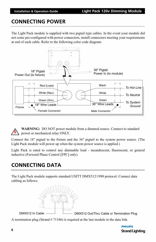
The Light Pack module is supplied with two pigtail type cables. In the event your module didnot come pre-configured with power connectors, install connectors meeting your requirementsat end of each cable. Refer to the following color code diagram:
WARNING: DO NOT power module from a dimmed source. Connect to standard power or mechanical relay ONLY.
Connect the 18" pigtail to the fixture and the 36" pigtail to the system power source. (TheLight Pack module will power up when the system power source is applied.)
Light Pack is rated to control any dimmable load - incandescent, fluorescent, or generalinductive (Forward Phase Control [FPC] only).etdimming.com
CONNECTING DATA
The Light Pack module supports standard USITT DMX512/1990 protocol. Connect data cabling as follows:
A termination plug (Strand # 71346) is required at the last module in the data link.
Red (Load)
White (Neu)
Green (Grn)
Female ConnectorFixture
18" Wire Leads
Black
White
Green36" Wire Leads
Male Connector
To Hot Line
To Neutral
To SystemGround
36" PigtailPower In (to module)
18" PigtailPower Out (to fixture)
DMX512 In Cable DMX512 Out/Thru Cable or Termination Plug
6

Light Pack 120v Dimming Module Installation & Operation Guide
SETTING MODE AND ADDRESS
Light Pack operating parameters, such as input/output modes and DMX512 addresses, can be easily configured to meet your requirements using the switches located inside the recess panel. The standard DIP switches configure input/output modes, while three rotary switches configure address and effects settings by providing three numerical dials: 100’s, 10’s and 1’s digits respectively.
For example, to set a DMX512 address (slot) of 355, you would set the 100’s dial to "3", the 10’s dial to "5", and the 1’s dial to "5". To configure the input/output modes, set each of the four standard DIP switches to either the ON or OFF setting. This toggles between two presets such as Non-Dim or Dim.
4321
450 microseconds800 microseconds*
Forward Phase Control*
115 VAC*120 VAC
Non-DimDim*
ON
Reverse Phase Control
100 10 1
000 = Disabled (only Focus button active)
001-512 = DMX512 Address
8XX = Fixed Light Output (Dim) Levelwhere XX is % level (99%=100%)
9XX = R21 Powered Raceway Address where XX is address (901-996)
* Default Setting
0987
6 5 432
1 0987
6 5 432
1
7XX = Effectswhere XX is effect parameter(refer to Effects section on next page)
6XX = Flicker Effect (controlled by DMX512)where XX is DMX512 address 01-99
513-599 = for future use
(997-999 are used for Test Mode)
Mode LED(see below)
0987
6 5 432
1
To access Dials and DIP Switches:Step 1. At side of module, locate recess panel.Step 2. Loosen thumbscrew and rotate cover.Step 3. Using #0 (small) flat head screwdriver,
set dials as required. Refer to diagram below.
Thumbscrew
DIP SwitchesAddress Dials
7
Installation & Operation Guide Light Pack 120v Dimming Module
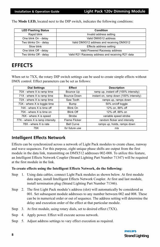
The Mode LED, located next to the DIP switch, indicates the following conditions:
EFFECTS
When set to 7XX, the rotary DIP switch settings can be used to create simple effects without DMX control. Effect parameters can be set as follows:
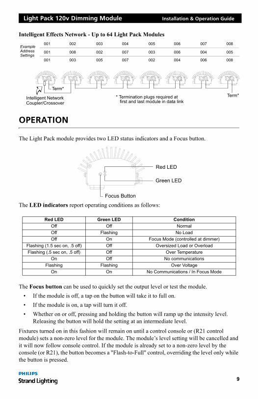
Intelligent Effects Network
Effects can be synchronized across a network of Light Pack modules to create chase, runway and wave sequences. For this purpose, eight unique phase shifts are output from the first module in the data link, transmitting on DMX512 addresses 002-008. To utilize this feature, an Intelligent Effects Network Coupler (Strand Lighting Part Number 71347) will be required at the first module in the link.
To create effects using the Intelligent Effects Network, do the following:
Step 1. Using data cables, connect Light Pack modules as shown below. At first module data input, install Intelligent Effects Network Coupler. At first and last module, install termination plug (Strand Lighting Part Number 71346).
Step 2. The first Light Pack module’s address (slot) will automatically be considered as 001. Set subsequent module addresses to any number between 002 and 008. These can be in numerical order or out of sequence. The address setting will determine the delay and execution order of the effect at that particular module.
Step 3. At first module, using rotary dials, set to desired effect (7XX).
Step 4. Apply power. Effect will execute across network.
Step 5. Adjust address settings to vary effect execution as required.
LED Flashing Status ConditionRapid blink Invalid address setting
One blink On - delay Valid DMX512 addressTwo blinks On - delay Valid DMX512 address and receiving DMX512
Slow blink Effects address settingOne blink Off - delay Valid Powered Raceway addressTwo blinks Off - delay Valid R21 Raceway address and receiving R21 data
Dial Settings Effect Description70X - where X is ramp time Bounce Up ramp up, instant off (100% intensity)71X - where X is ramp time Bounce Down instant on, ramp down (100% intensity)72X - where X is ramp time Saw Tooth ramps up, ramps down73X - where X is toggle time Bump 50% on/off toggle
74X - where X is time off Blink On 12% on, 88% off75X - where X is time on Blink Off 12% off, 88% on76X - where X is speed Strobe variable speed strobe
77X - where X is lamp intensity Flame Flicker random flicker and intensity78X - where X is rate Bell Curve ramps up, holds, ramps down
79X for future use n/a
8
Light Pack 120v Dimming Module Installation & Operation Guide
Intelligent Effects Network - Up to 64 Light Pack Modules
OPERATION
The Light Pack module provides two LED status indicators and a Focus button.
The LED indicators report operating conditions as follows:
The Focus button can be used to quickly set the output level or test the module. • If the module is off, a tap on the button will take it to full on. • If the module is on, a tap will turn it off. • Whether on or off, pressing and holding the button will ramp up the intensity level.
Releasing the button will hold the setting at an intermediate level.
Fixtures turned on in this fashion will remain on until a control console or (R21 control module) sets a non-zero level for the module. The module’s level setting will be cancelled and it will now follow console control. If the module is already set to a non-zero level by the console (or R21), the button becomes a "Flash-to-Full" control, overriding the level only while the button is pressed.
Red LED Green LED ConditionOff Off NormalOff Flashing No LoadOff On Focus Mode (controlled at dimmer)
Flashing (1.5 sec on, .5 off) Off Oversized Load or OverloadFlashing (.5 sec on, .5 off) Off Over Temperature
On Off No communicationsFlashing Flashing Over Voltage
On On No Communications / In Focus Mode
001
* Termination plugs required at
001Example
001
AddressSettings
003
008
002
005
002
003
007
007
004
002
003
005
004
006
006
006
004
007
008
005
008
first and last module in data linkIntelligent NetworkCoupler/Crossover
Term*Term*
Focus Button
Red LED
Green LED
9
Installation & Operation Guide Light Pack 120v Dimming Module
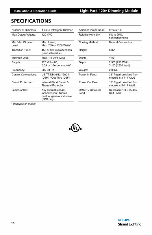
SPECIFICATIONS
* Depends on model
Number of Dimmers: 1 IGBT Intelligent Dimmer Ambient Temperature: 0° to 50° C
Max Output Voltage: 120 VAC Relative Humidity: 5% to 95%, non condensing
Min./Max Dimmer Load:
Min. 1 Watt, Max. 750 or 1200 Watts*
Cooling Method: Natural Convection
Transition Time: 450 or 800 microseconds (user selectable)
Height: 6.82"
Insertion Loss: Max. 1.5 Volts (2%) Width: 4.53"
Supply: 120 Volts AC, 6.5A or 10A per module*
Depth: 2.93" (750 Watt) 3.18" (1200 Watt)
Frequency: 50 / 60 Hz Weight: 2.0 lbs.
Control Connections: USITT DMX512/1990 In (D5M) / Out/Thru (D5F)
Power In Feed: 36" Pigtail provided from module is 3-#14 AWG
Circuit Protection: Internal Short Circuit & Thermal Protection
Power Out Feed: 18" Pigtail provided from module is 3-#14 AWG
Load Control: Any dimmable load - incandescent, fluores-cent, or general inductive (FPC only)
DMX512 Data Link Load
Represent 1/4 ETA 485 Unit Load
10

Light Pack 120v Dimming Module Installation & Operation Guide
CATALOG NUMBER REFERENCE
Light Pack 120v Modules
Strand P/N Description
71300 Light Pack 750 watt, Bare leads71301 Light Pack 750 watt, with GP connectors71302 Light Pack 750 watt, with GTL connectors71303 Light Pack 750 watt, with GR connectors71310 Light Pack 1200 watt, Bare leads71311 Light Pack 1200 watt, with GP Connectors71312 Light Pack 1200 watt, with GTL connectors71313 Light Pack 1200 watt, with GR connectors
11
Installation & Operation Guide Light Pack 120v Dimming Module
NOTES
12
Light Pack 120v Dimming Module Installation & Operation Guide
NOTES
13

Part No. 2-450188-010