story of the book - pearson canada setup step-by -ste p 1 2a ... process and welding position....
TRANSCRIPT

viii
today’s students and instructors need to do more in less time than ever before. Welding was written from the ground up to be both comprehensive and concise. each chapter is cleanly designed and covers exactly what students need to know to enter the workforce. the material is presented with striking images, easy-to-read reference charts and tables, and detailed step-by-step procedures.
New to this editioN
Based on peer review several major changes were made to the text as outlined below:
• An introductory pipe welding chapter has been added. topics covered include joint preparation, weld joint fit-up, tack welds, root pass welding, fill pass weld-ing, cap pass welding, and technique. the chapter closes with welding tables that, when used in conjunction with the welding process chapters, act as a step-by-step guide for welding pipe.
• Welding Alloys has been expanded into two separate chapters- Welding Ferrous Alloys and Welding nonferrous Alloys. Information was reorganized, for a more practical approach to setting up and completing welds with indi-vidual metal alloys.
• components of Welding Design have been relocated to the end of Metals and Welding Metallurgy, adding an unique, practical, and measurable view of metal warpage and distortion.
• the Welding codes and testing chapter is divided into two separate chap-ters- Welding codes and Weld testing. this logical division makes information easier to find and aides instructors in course design.
• the Welding costs chapter has been streamlined into easy to use tables in Appendix F. tables are structured in a simple manner that students can more easily understand.
story of the Book
the authors have experience both in industry and in the classroom. their industry experience brings together knowledge of welding and manufacturing, welding inspection and quality control, training, weld code testing, power source design,
preface
A01_HOFF6344_02_SE_FM.indd 8 09/01/16 5:40 pm

PreFAce ix
troubleshooting, and customer service. those collective industry experiences and more than 60 years of combined instructional expertise have inspired the writing of this textbook. As instructors, the authors wanted to produce an accessible book that covers welding in a clear and concise manner. After an introduction to welding and to welding safety, they gave each major welding process its own chapter so they could easily be discussed in the classroom. Following the weld processes, their chapters focus on critical topics, such as codes, destructive and non-destructive weld testing, welding symbols, welding metallurgy, welding fer-rous and nonferrous alloys, and welding power sources. Most textbooks do not cover smaller diameter electrodes well. Welding does. the authors’ goal was to create a text suitable for high schools and postsecondary schools, for industrial use, or by the home hobbyist, and they have done just that with Welding.
orgaNizatioN
First, the book orients students with basic information on welding careers and welding safety. then, welding chapters follow, with uniquely detailed step-by-step weld setups and techniques. the authors devote an entire chapter to each of the common weld processes. Within those chapters they take the weld setup and break it down into its most important steps, providing students with instructions and photos. students are visual learners, and this step-by-step format makes the material easier to learn and easier to reference later in the semester and even later in students’ careers. the chapters cover important information with easy-to-read technical tables.
next, the chapters turn to metallurgy and alloys, codes and costs, and other critical welding topics. Finally, the appendices cover additional topics, such as troubleshooting, conversion, and pipes and beams.
A01_HOFF6344_02_SE_FM.indd 9 09/01/16 5:40 pm

Chapter key terms each chapter opens with a list of key terms with page references for the chapter. this provides for quick access and easy review by students.
KEY TERMS
Air-Cooled Torch 171
Water-Cooled Torch 171
Torch Body 174
Cup 174
Collet 174
Collet Body 174
Back Cap 175
Tungsten Electrode 178
Inert Gas 183
Asphyxiant 184
Venire Control 185
Postflow 186
Preflow 186
Cathotic Etching 188
High-Frequency 190
Autogenous Weld 190
Chapter iNtroduCtioN
these introductions provide a general overview of the chapter content. they are a preview of the essential content, which often includes historical information, that will be featured in the coming pages.
INTRODUCTION
Gas Tungsten Arc Welding (GTAW) is an extremely useful welding process that uses a nonconsumable tungsten electrode to conduct welding current. Base metal and arc gap resistance to current flow creates heat, causing the base metal to melt, forming a molten weld pool. The weld can then be finished by blending base metal pools together or by manually adding filler metal. FIGURE 6-1 shows a typical GTAW torch and welding arc. In the past, this welding process was called TIG welding. TIG stands for Tungsten Inert Gas. While the acronym TIG is not entirely inaccurate, GTAW is the universally acceptable acronym for this welding process.
Chapter QuestioNs/assigNmeNts
Great for study review and comprehension checks, these end-of-chapter questions help students assess their understanding of the material.
CHAPTER QUESTIONS/ASSIGNMENTS
MULTIPLE CHOICE
1. What is another common name for GTAW?a. Gas Arc Welding (GAW)b. Manual Filler Welding (MFW)c. Tungsten Inert Gas (TIG)d. Tungsten Electrode Welding (TEW)
4. The air-cooled welding torch uses what to remove heat?a. Carbon dioxide shielding gasb. Cooled waterc. Argon shielding gasd. 75% argon/25% carbon dioxide shielding gas mixture
FILL IN THE BLANK
12. The tungsten electrode is a electrode that is used to conduct welding current.
13. A constant power source is the type used for GTAW.
19. is the process in which positive ions are re leased from the electrode and strike the oxides on the surface of the aluminum. The loose oxides are then lifted away by the current flow from the aluminum to tungsten.
x PreFAce
a solid fouNdatioN for learNiNg
Chapter learNiNg oBjeCtives each chapter begins with clearly stated objectives that enable students to focus on what they should achieve and know by the end of the chapter.
In this chapter, the reader will learn how to:
1. Use the Gas Tungsten Arc Welding process
safely.
2. List what types of power sources and other
peripheral components make up the Gas
Tungsten Arc Welding process.
3. Identify the characteristics and correctly use the
various controls on power sources.
4. Determine which polarity is best for the base
metal used and desired outcome.
5. Select the correct electrode for the base metal
used and the desired outcome.
6. Select the correct shielding gas.
7. Properly set up for Gas Tungsten Arc Welding by
adjusting the filler addition amount, travel speed,
work angles, and electrode-work distance.
LEARNING OBJECTIVES
A01_HOFF6344_02_SE_FM.indd 10 09/01/16 5:40 pm
PreFAce xi
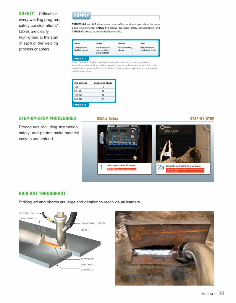
safety critical for every welding program, safety considerations/tables are clearly highlighted at the start of each of the welding process chapters.
SAFETY
TABLES 6-1 and 6-2 show some basic safety considerations related to work-place environments. TABLE 6-1 shows the basic safety considerations and TABLE 6-2 shows recommended lens shade.
TABLE 6-1
Read “Chapter 2: Safety in Welding” for detailed discussion of safety related to workplace environment, workplace hazards, personal protective equipment, electrical consideration, gases and fumes, ventilation, fire prevention, explosion, and compressed cylinders and gases.
Head Body Hands Feet
Safety glassesWelding helmet
Flame-resistantwool or cottonpants and shirt
Leather weldinggloves
High-top leathersafety work boots
TABLE 6-2
Arc Current Suggested Shade
< 50 8
50–150 10
150–250 12
250–400 14
step-By-step proCedures
Procedures including instruction, safety, and photos make material easy to understand.
SMAW Setup STEP-BY-STEP
1 2a
riCh art throughout
striking art and photos are large and detailed to reach visual learners.
GRANULAR FLUX FEED
ELECTRODE
WELD BEAD
BASE METAL
ELECTRIC LEAD
GRANULAR FLUX
TORCH
A01_HOFF6344_02_SE_FM.indd 11 09/01/16 5:40 pm

supplemeNts
supplements are a crucial part of any book these days, and Welding includes a unique package for both students and instructors. to access supplemen-tary materials online, instructors need to request an instructor access code. Go to www.pearsonhighered.com/irc to register for an instructor access code. Within 48 hours of registering, you will receive a confirming e-mail in-cluding an instructor access code. once you have received your code, locate your text in the online catalog and click on the Instructor resources button on the left side of the catalog product page. select a supplement, and a login page will appear. once you have logged in, you can access instructor mate-rial for all Pearson education textbooks. If you have any difficulties accessing the site or downloading a supplement, please contact customer service at http://247pearsoned.custhelp.com.
Instructor’s resource Manual the Instructor’s Resource Manual (IsBn-10: 0-13-401645-9) includes chapter-by-chapter assistance through modifiable lesson plans, a sample syllabus, objectives, and answers to the end-of-chapter review questions.
PowerPoInt PresentatIon the PowerPoint Presentation (IsBn-10: 0-13-401706-4) features a lecture outline format with key talking points. It includes art from the textbook to enhance the classroom experience and to help instructors prepare for class.
testGen this electronic question bank (IsBn-10: 0-13-401637-8) can be used to develop customized quizzes, tests, and/or exams.
student’s weldInG lab Manual (priNt) A printed Student Welding Lab Manual (IsBn-10: 0-13-407007-0) is also available. With more than 170 labs in all, this outstanding resource includes challenging lab exercises for the more common welds that students are likely to encounter.
xii PreFAce
A01_HOFF6344_02_SE_FM.indd 12 09/01/16 5:40 pm

Chapter 7
PiPe Welding
215
In this chapter, the reader will learn how to:
1. Identify the challenges of welding pipe positions
compared to plate welding.
2. Determine how to correctly prepare and clean
a weld joint.
3. Understand the importance of fit up and its
relationship to the weld keyhole.
4. Properly place and clean up tack welds.
5. Distinguish the differences in making root
passes on several base metal types.
6. Describe the importance of fill pass layer thickness
and width to ensure a successful weld.
7. Identify several criterions that determine the
success of a cap pass.
8. Select a welding procedure for a specific welding
process and welding position.
LearnIng ObjectIves Key terms
Tack Weld 219
Keyhole 218
Root Pass 220
Hot Pass 222
Fill Pass 222
Cap Pass 222
M07_HOFF6344_02_SE_C07.indd 215 09/01/16 5:43 pm

216 CHaPTeR 7
IntroductIon to pIpe weldIng and posItIons
Using advanced welding processes and techniques requires both an understand-ing of basic welding fundamentals and the skills required to perform welds in multiple positions. The skills used to perform the pipe procedures described here are not beginning welding skills. They require that the welder already can perform welds successfully in the 1G, 2G, 3G, and 4G positions. Since pipe welding most often requires open root welding, open root plate welding in all positions is good preparation to acquire the skill needed to produce complete joint penetration (FIgure 7-1) welds on pipe. Both the 5G and 6G pipe welding positions require the ability to weld in multiple positions. For example, the 5G encompasses weld-ing in the flat, vertical, and overhead positions, and the 6G involves welding in all positions. While producing fillet welds on pipe present some difficulty compared to plate welding, the discussion here is focused on groove welding.
COMPLETE JOINT PENETRATION
FIgure 7-1 Complete Joint Penetration.
what are the Factors that Make pIpe weldIng Both dIFFerent and More challengIng than weldIng plate MaterIals? Pipe welding entails maintaining welding angles around the circumference of pipes. Rather than welding in one linear direction, the welder must constantly adjust the welding travel angle to account for the curvature of the pipe. Maintaining visibility of the weld pool is also complicated for welding fixed position pipe. FIgure 7-2 shows common aWS pipe welding positions for groove joints.
Joint design Where fillet welds are common on plate welding design, groove welds are more common in pipe applications where complete joint penetration is needed. Open root groove designs have variations of those elements—groove or bevel angle, root face, and root opening—shown in FIgure 7-3. a good practice for selecting a groove design is to follow recommendations from a welding code or standard directly related to the pipe welding being done. Welding codes, such as AWS D1.1 Structural Welding Code-Steel, and ASME Boiler and Pressure Vessel Code, Section IX: Welding and Brazing Qualifications, contain recommended practices and requirements for welding carbon steel pipe.
M07_HOFF6344_02_SE_C07.indd 216 09/01/16 5:43 pm

PIPe WelDInG 217
45°
Flat grooveposition 1G (rotated)
Vertical grooveposition 5G
Horizontalgroove position 2G
All positiongroove 6G
FIgure 7-2 Common pipe welding positions.
GROOVE ANGLE
BEVEL ANGLE
ROOT OPENING
ROOT FACE FIgure 7-3 Groove joint design.
JoInt preparatIon
what are the MInIMuM requIreMents For JoInt preparatIon BeFore asseMBlIng parts For weldIng? The first step for joint prep-aration is to determine specific dimensions for the groove design. The groove angle and root opening must be sufficient enough to allow for access of the elec-trode to ensure complete joint penetration and to allow for fusion to the groove faces and between all weld passes and layers (FIgure 7-4). For larger nozzle diameters used with GMaW and GTaW, the included angle may be as much as 70 degrees on v-groove joints. If the joint root is easily accessible, an included angle of 60 degrees may be used.
edge PreParation The bevel angle should be prepared by machining within the tolerances of an established welding procedure specification. The root face can be machined or ground after beveling. In some cases, the bevel angle, root
M07_HOFF6344_02_SE_C07.indd 217 09/01/16 5:43 pm

218 CHaPTeR 7
face, and inside surface of the pipe are prepared in one operation with a pipe beveling machine equipped with multiple cutting tools. The inside edges of the pipe must be in alignment to ensure complete joint penetration throughout the full weld length.
Final Cleaning Before setting up for welding, the pipe must be cleaned suf-ficiently to ensure fusion and to eliminate any form of contamination entering the weld zone. Mill scale, varnish, paint, rust, or other contaminants must be removed prior to joint fit-up to a distance of 1 inch (2.54 cm) from the bevel edge. These possible contaminants can be removed by mechanical means such as grinding. Further, any oils or fluids from cutting or storage must be removed with a clean-ing solvent approved for welding operations to eliminate porosity or unwanted metallurgical effects. With aluminum base metals, oxide removal is necessary immediately prior to welding, for each weld pass, to ensure proper fusion.
FIgure 7-4 Weld layers in groove weld.
weld JoInt FIt up
how are pIpe pIeces held In place For weldIng? The pipe pieces must be secured in a manner that keeps the root edges in alignment, while main-taining a consistent root opening. If the inside edges of the pipe are not aligned, it will be difficult to maintain complete joint penetration through the full length of the weld. at the same time, if the root opening is narrower on one side of the pipe and wider on the other, it is difficult to control both fusion in the narrow opening and to eliminate excessive melt-through of the wider opening.
To ensure proper alignment on the job, one technique uses pipe clamps. These allow for precise alignment, fitting up the pipe for welding. Many com-mercial styles of both internal and external pipe clamps are available. These are often cost prohibitive in small schools shops. In this case, other alternatives exist. angle iron or channel iron can be used for alignment, with the addition of a clamp-ing mechanism (FIgure 7-5).
what are the FIrst steps In ensurIng a successFully welded pIpe JoInt? Before welding begins, and this applies to all or any single weld pass or layer, equipment must be set properly, allowing for ease of weld starts. all welds with all processes must have arc initiation within the weld groove, where subsequent weld passes will melt out the effects of initiating the arc (arc starts).
The next factor for success is to develop and maintain a keyhole at the lead-ing edge of the weld pool in the joint root. a keyhole is a small circular hole
FIgure 7-5 Channel Iron Used for alignment.
M07_HOFF6344_02_SE_C07.indd 218 09/01/16 5:43 pm

PIPe WelDInG 219
through the joint root, at the leading edge of the weld pool, on tack and root pass welds. It is desired to ensure fusion through the joint root. a properly shaped and sized keyhole (FIgure 7-6) will melt both root faces and ensure adequate root fusion. Too large a keyhole will cause excessive melt through which is difficult to repair. However, if the keyhole closes, root fusion may be lost, which is equally unacceptable. tabLe 7-1 lists some causes and solutions regarding problems encountered maintaining a keyhole on all welds in the joint root. FIgure 7-6 Keyhole size and
shape-both beveled pipe edges are melted.
Table 7-1
Troubleshooting keyhole and root fusion.
Problem causes solutions
Keyhole too bigExcessive melt-through
Amps too high Decrease amps
Root opening too big Reduce root opening
Root face too small Increase root face
Starting to push electrode Correct drag angle
Keyhole too smallIncomplete root fusion
Amps too low Increase amps
Root opening too small Increase root opening
Root face too large Reduce root face
Too steep drag angle Increase to push
MakIng and placeMent oF tack welds
what Is the FIrst step In weldIng aFter JoInt preparatIon and FIt-up are coMplete? Once fit-up is complete, it is time for placement of tack welds. a tack weld is a permanent weld used to fit up and hold the weld joint in place for welding. Tack welds are an integral part of the weld assembly. They must have complete joint penetration, and be large enough to hold the pipe rigidly in place to withstand expansion and contraction forces introduced during place-ment of the root pass. Otherwise, the weld joint will not stay properly aligned, or the root opening may close preventing fusion through the root of the joint.
Positioning of tack welds, both in number and location, is imperative to success in achieving complete joint penetration, meeting strength, and code requirements. Tack welds spaced equal distance and centered at the four quadrants of the pipe circumference as shown in FIgure 7-7 are sufficient for most small diameter pipe applications. For larger diameter pipe, more tack welds may be placed at intervals frequent enough to eliminate closing of the root opening. When welding pipe for procedure qualification or welder qualification, tack welds maybe placed at positions other than were test pieces are taken.
The final steps for finishing of tack welds are to clean by chipping and brush-ing, followed by grinding. Grind the weld to feather it out to a uniform, smooth contour. It is important to smooth out cold weld starts, where build-up is convex and likely too thick to accept fusion through the root of the subsequent root pass.
M07_HOFF6344_02_SE_C07.indd 219 09/01/16 5:43 pm

220 CHaPTeR 7
at the same time, the welder must take care not to overgrind and remove too much of the tacks weld. This may result in melting the tack weld completely out and the root faces pulling together, reducing root fusion.
In the case of welding aluminum, GTaW tack welds are preferred over GMaW tack welds. Cold starts can be a problem with GMaW and this may obstruct fusion in the root pass. Use of a welding power source with a “hot start” function can help to reduce this problem.
121
2
3
4
56
7
8
9
10
11
FIgure 7-7 Placement of tack welds relative to clock positions.
root pass weldIng
The root pass is the initial pass deposited after the pipe is fit-up and tack-welded together. Where final visual inspection is concerned, the root pass and the cover or cap-pass are the decisive factors for determining whether or not welding was successful. If the pipe has been prepared with the correct groove design, and fit-up and the tack welding have been done correctly, welding the root pass can proceed.
It is important to start the initial weld of the root pass by starting the arc at least ¼ inches back (overlapping) on the tack weld and progress forward from there. This will allow the weld pool to develop, creating enough heat to cause proper melt through and fusion with the tack weld and tie into the keyhole. This same method must be repeated with each tie-in (restart) to complete the root pass.
Remember, the goal is to finish the root pass with complete fusion, both on the root side (FIgure 7-8) and the fusion face and toes of the weld (FIgure 7-9). tabLe 7-1 lists the causes and solutions to problems encountered with root fusion. The factors the welder controls that influence fusion are amperage, travel and work angles, arc length, and travel speed. One other factor is the position of the weld. For example, vertical down-welding requires higher travel speeds and is limited to thinner pipe thicknesses. Vertical up-welding may be done with smaller diameter electrodes to allow for both proper root fusion and weld pool control.
FIgure 7-8 Fusion on the root side-both beveled pipe edges are melted.
M07_HOFF6344_02_SE_C07.indd 220 09/01/16 5:43 pm

PIPe WelDInG 221
Root pass procedures vary with some alloys other than carbon steel. In the case of stainless steels, open root welding is accomplished by back purging the inside of the pipe with either argon or nitrogen gases. as an alternative, one of various types of consumable inserts (FIgure 7-10), backing rings, or back-ing tape can be used to prevent the root from oxidizing effects of atmospheric oxygen. Consumable inserts are commercially available for most common base metal alloys.
When welding aluminum alloys, it is a common practice to use backing rings that fit inside the pipe and act as a backing bar. In addition, the extended-land bevel joint may be used (FIgure 7-11). This design eliminates the need for a backing ring.
FIgure 7-9 Fusion on weld face and toes.
INVERTED T J K
RECTANGULAR
FIgure 7-10 Consumable inserts for open root welding.
FIgure 7-11 extended land.Source: aWS D1.2/D1.2M:2003, Figure 3.31 reproduced with permission of the american Welding Society, Miami, Florida.
M07_HOFF6344_02_SE_C07.indd 221 09/01/16 5:43 pm

222 CHaPTeR 7
FIll pass weldIng
other than adJustIng the power source and selectIng an elec-trode, what else can the welder do to IMprove weld qualIty? Once the root pass is completed, it must be cleaned thoroughly to ensure that any slag, cold starts, or any other irregularity, which may reduce fusion in the next passes, are re-moved. Interpass cleaning–chipping, wire brushing, and grinding are necessary steps in producing sound welds.
When using eXX10 and eXX11 class electrodes with SMaW, a hot pass may be used after brushing and grinding. Due to the turbulent nature of the arc, electrode manipulation, and narrow groove faces of the joint root, these electrodes tend to leave a weld face that can be more difficult to clean than those of welds made with low-hydrogen-type electrodes. a hot pass is a second pass, at higher welding cur-rents, used to help eliminate and float out any difficult to remove slag particles.
after the root pass and hot pass (if needed) are completed, the groove is filled by layering with overlapping weld beads. Fill passes are used to complete the interior portion of multipass groove welds. Fill passes are used to nearly fill the groove, leaving only enough space for the cap passes, the final weld layer. It is necessary to maintain an even layer-by-layer approach at this stage.
what lIMIts exIst For weld Bead wIdth or thIckness? Whether using stringer or weave beads, code requirements must be met. Some codes set limits on bead width and layer thickness (FIgure 7-12) for qualified procedures. AWS D1.1 Structural Welding Code-Steell-2010, e.g., limits a fill pass layer thickness for SMaW. It also limits single pass layer width for GMaW and FCaW processes.
LAYERWIDTH
LAYERTHICKNESSFIgure 7-12 example of layer
thickness and width.
cap pass weldIng
The cap pass is the final visible weld layer on a multipass groove weld. Several factors must be met for the final weld and weld layer to be acceptable. First of all, the weld penetration including reinforcement has a minimum thickness equal to the base metal thickness. Second, the reinforcement height cannot exceed code requirements, and in most cases, this is 1/8” maximum. The cap pass width should be as narrow as possible while filling the groove completely. Finally, the weld must have a smooth transition to the base metal at the weld toes. FIgure 7-13 shows a
M07_HOFF6344_02_SE_C07.indd 222 09/01/16 5:43 pm

PIPe WelDInG 223
completed groove joint filled with multipass stringer weld beads and all layers: root pass, hot pass, fill passes, and cap pass.
ROOT PASS
HOT PASS
CAP PASS
FILL PASSES
FIgure 7-13 completed groove weld and layers (stringer bead technique).
90°
5°
FIgure 7-14 GTaW torch and filler metal positions.
weldIng processes and procedures
what processes and procedures are used For pIpe weldIng? For shielded metal arc welding, the eXX10 and eXX11 electrode classifications are commonly used for welding the root pass on carbon steel pipe. These electrodes have an arc characteristic that provides good root penetration and fusion while minimizing slag entrapment, where the low-hydrogen-type electrodes like the eXX18 fail to produce the desired results for root pass welding. The eXX10 and eXX11 electrodes can be used exclusively, or they may be used for the root pass, with remaining fill and cap passes completed with the low-hydrogen electrodes.
Gas tungsten arc welding provides superior weld quality in food-grade applications and for pipe welding, where nondestructive examination such as ultrasonic and radiographic testing may be required. The use of argon shielding without fluxes, and with the aid of remote amperage technology, allows a great de-gree of arc control for open root welding. These factors make GTaW a good choice for small diameter, thin walled pipe. In addition to thin walled pipe, GTaW can be a good choice for root pass welding, while completing the remaining fill and cap passes with a higher deposition process like GMaW or with low-hydrogen SMaW.
Given the more complicated application, heating with the torch and the man-ual addition of filler metal, a couple illustrations will help review techniques unique to GTaW. FIgure 7-14 demonstrates the addition of the filler metal in relation to the pipe base metal and the torch travel angle. Too steep of a travel angle,
M07_HOFF6344_02_SE_C07.indd 223 09/01/16 5:43 pm

224 CHaPTeR 7
one that directs the arc toward the filler metal and away from the base metal will cause the filler metal to ball up and reduce fusion.
The work angle for 1G and 5G welds holds the torch directly perpendicular to the work surface as shown in torch position “a” in FIgure 7-15. Positions “B” and “C” show alternate torch positions for walking the cup along the groove faces, which provides good control of the weld pool and produces a good weld bead profile.
Finally, GMaW can be used where advantageous for pipe welding. While short circuit transfer has its limits when heavy wall pipe applications are con-cerned, it has its place on thin-walled pipe and for welding root passes where it performs well, especially with vertical down-welding progression. In addition, new advances in welding power source and process design allow a very high degree of control for root pass welding and bridging gaps.
Use the following tables 7-2 through 7-13, and recommendations as a basic step-by-step instruction along with the techniques sections of Chapter 3 Shielded Metal arc Welding, Chapter 4 Gas Metal arc Welding and Chapter 6 Gas Tungsten arc Welding. FIgures 7-18 through 7-41 demonstrate travel angles and work angles for each process and welding position. FIgure 7-16 shows recommended bevel angle, root opening, and root face dimensions. FIgure 7-17 shows the vari-ous welding progressions associated with the 5G pipe position. Welding progres-sions for 6G pipe are similar to that of 5G pipe, with some horizontal progression included.
C BA
FIgure 7-15 Torch position and work angle view (when walking the cup, rest the nozzle on the groove face and use appropriate travel angle).
3/32"+–1/32"3/32"+–1/32"
30–37.5°
FIgure 7-16 Groove design.
M07_HOFF6344_02_SE_C07.indd 224 09/01/16 5:43 pm

PIPe WelDInG 225
FLAT
WELDING PROGRESSIONS ASSOCIATEDWITH THE 5G PIPE POSITION
OVERHEAD
VERTICAL VERTICAL
FIgure 7-17 Welding progressions associated with the 5G pipe position.
smaW pipe
1g Flat groove position
Instructions (refer to Chapter 3 techniques)
Base metal Carbon Steel
Current DCEP
Root pass EXX10 or EXX11 classification electrodes◾◾ Backhand stringer, straight step whipping
FIgure 7-18 Travel angle.
30–37.5°
90°
FIgure 7-19 Work angle.
Table 7-2
M07_HOFF6344_02_SE_C07.indd 225 09/01/16 5:43 pm

226 CHaPTeR 7
Table 7-2 Continued
smaW pipe
1g Flat groove position
Hot pass As needed
Fill passes Option 1 Option 2
EXX10 or EXX11 classification electrodes
◾◾ Backhand stringer, straight step whipping, or circular weave
EXX18 classification electrode◾◾ Stringer bead
Cover pass Option 1 Option 2
EXX10 or EXX11 classification electrodes
◾◾ Backhand stringer, straight step whipping, or circular weave
EXX18 classification electrode◾◾ Stringer bead
Comments Use as little weave as possible
smaW pipe
2g Horizontal groove position
5–15°
TRAVEL ANGLE
FIgure 7-20 Travel angle.
Table 7-3
M07_HOFF6344_02_SE_C07.indd 226 09/01/16 5:43 pm
PIPe WelDInG 227
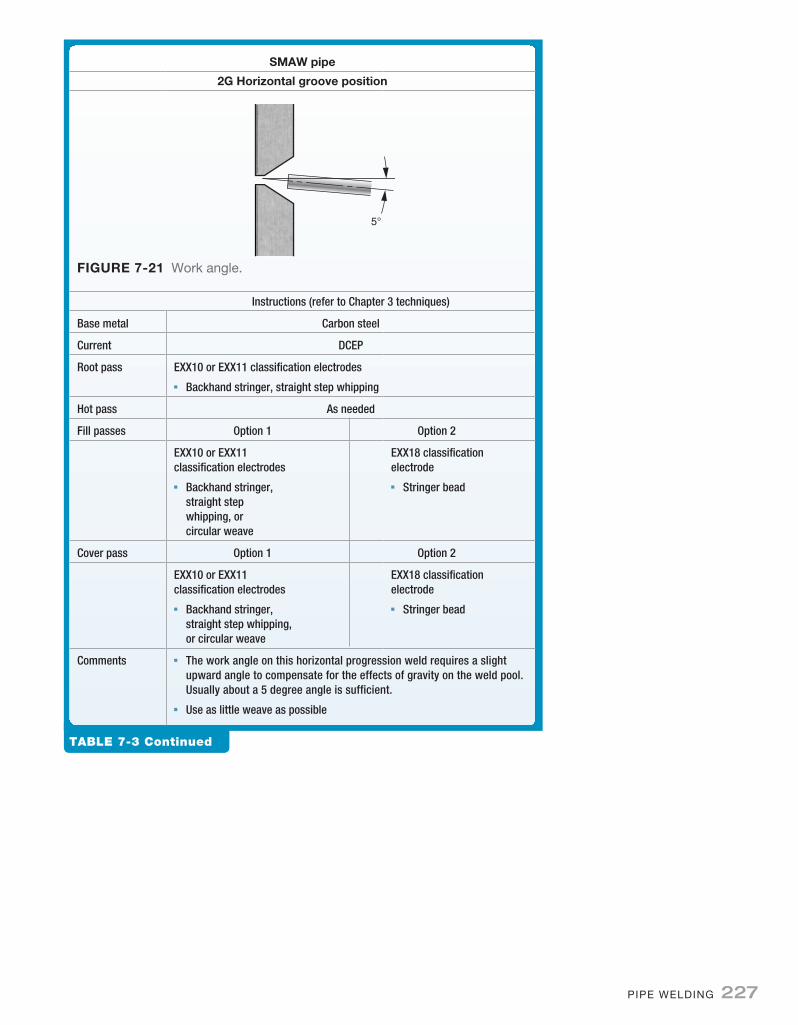
Table 7-3 Continued
smaW pipe
2g Horizontal groove position
Instructions (refer to Chapter 3 techniques)
Base metal Carbon steel
Current DCEP
Root pass EXX10 or EXX11 classification electrodes◾◾ Backhand stringer, straight step whipping
Hot pass As needed
Fill passes Option 1 Option 2
EXX10 or EXX11 classification electrodes
◾◾ Backhand stringer, straight step whipping, or circular weave
EXX18 classification electrode
◾◾ Stringer bead
Cover pass Option 1 Option 2
EXX10 or EXX11 classification electrodes
◾◾ Backhand stringer, straight step whipping, or circular weave
EXX18 classification electrode
◾◾ Stringer bead
Comments ◾◾ The work angle on this horizontal progression weld requires a slight upward angle to compensate for the effects of gravity on the weld pool. Usually about a 5 degree angle is sufficient.
◾◾ Use as little weave as possible
5°
FIgure 7-21 Work angle.
M07_HOFF6344_02_SE_C07.indd 227 09/01/16 5:43 pm

228 CHaPTeR 7
smaW pipe
5g vertical groove position
Instructions (refer to Chapter 3 techniques)
Base Metal Carbon Steel
Current DCEP
Progression Vertical down
Root pass EXX10 or EXX11 classification electrodes◾◾ Backhand stringer, straight step whipping
Hot pass As needed
Fill passes EXX10 or EXX11 classification electrodes◾◾ Backhand stringer, straight step whipping
Cover pass EXX10 or EXX11 classification electrodes◾◾ Backhand stringer, straight step whipping
Progression Vertical up
Root pass EXX10 or EXX11 classification electrodes◾◾ Backhand stringer, straight step whipping, or circular weave
5–15°
TRAVEL ANGLE
FIgure 7-22 Travel angle.
90°
FIgure 7-23 Work angle.
Table 7-4
M07_HOFF6344_02_SE_C07.indd 228 09/01/16 5:43 pm

PIPe WelDInG 229
Table 7-4 Continued
smaW pipe
5g vertical groove position
Hot pass As needed
Option 1 Option 2
Fill passes EXX10 or EXX11 classification electrodes
◾◾ Backhand stringer, straight step whipping, or circular weave
EXX18 classification electrode◾◾ Stringer or weave
Cover pass EXX60 classification electrodes◾◾ Backhand stringer, straight step
whipping, or circular weave
EXX18 classification electrode◾◾ stringer or weave
Comments Use as little weave as possible
smaW pipe
6g vertical groove position
Instructions (refer to Chapter 3 techniques)
Base Metal Carbon Steel
Current DCEP
Progression Vertical down
Root pass EXX10 or EXX11 classification electrodes◾◾ Backhand stringer, straight step whipping
5–15°TRAVEL ANGLE
FIgure 7-24 Travel angle.
90°FIgure 7-25 Work angle.
Table 7-5
M07_HOFF6344_02_SE_C07.indd 229 09/01/16 5:43 pm

230 CHaPTeR 7
Table 7-5 Continued
smaW pipe
6g vertical groove position
Hot pass As needed
Fill passes EXX10 or EXX11 classification electrodes◾◾ Backhand stringer, straight step whipping
Cover pass EXX10 or EXX11 classification electrodes◾◾ Backhand stringer, straight step whipping, or circular weave
Progression Vertical up
Root pass EXX10 or EXX11 classification electrodes◾◾ Backhand stringer, straight step whipping, or circular weave
Hot pass As needed
Option 1 Option 2
Fill passes EXX10 or EXX11 classification electrodes
◾◾ Backhand stringer, straight step whipping, or circular weave
EXX18 classification electrode◾◾ Stringer or weave
Cover pass ◾◾ EXX10 or EXX11 classification electrodes
◾◾ Backhand stringer, straight step whipping, or circular weave
EXX18 classification electrode◾◾ Stringer or weave
Comments Use as little weave as possible
gtaW pipe
1g Flat groove position
5–15°
TRAVEL ANGLE
START
STOP(KEYHOLE)
FIgure 7-26 Travel angle.
Table 7-6
M07_HOFF6344_02_SE_C07.indd 230 09/01/16 5:43 pm

PIPe WelDInG 231
Table 7-6 Continued
gtaW pipe
1g Flat groove position
Instructions (refer to Chapter 6 techniques)
Base Metal Carbon Steel
Current ◾◾ DCEN
Shielding ◾◾ Argon (100%)
Root pass ER70S-2 classification electrodes◾◾ Use forehand stringer, circular weave, or walk the cup
Second passand Fill pass
Option 1: Used for thin wall pipe or tubing
ER70S-2 classification electrodes◾◾ Use forehand stringer, circular weave, or walk the cup
Cover pass ER70S-2 classification electrodes◾◾ Use forehand stringer, circular weave, or walk the cup
Fill passes Option 2 Option 3
Use SMAW Procedures Use GMAW Procedures
Cover pass Use SMAW Procedures Use GMAW Procedures
Comments ◾◾ Pulsed GTAW can be substituted on the root pass for superior weld pool and keyhole control.
◾◾ Use as little weave as possible
30–37.5°
90°
FIgure 7-27 Work angle.
M07_HOFF6344_02_SE_C07.indd 231 09/01/16 5:43 pm

232 CHaPTeR 7
gtaW pipe
2g Horizontal groove position
Instructions (refer to Chapter 6 techniques)
Base Metal Carbon Steel
Current ◾◾ DCEN
Shielding ◾◾ Argon (100%)
Root pass ◾◾ ER70S-2 classification electrodes◾◾ Use forehand stringer, circular weave, or walk the cup
Second passand Fill pass
Option 1: Used for thin wall pipe or tubing
◾◾ ER70S-2 classification electrodesUse forehand stringer, circular weave, or walk the cup
Cover pass ER70S-2 classification electrodesUse forehand stringer, circular weave, or walk the cup
5–15°
TRAVEL ANGLE
FIgure 7-28 Travel angle.
5°
FIgure 7-29 Work angle.
Table 7-7
M07_HOFF6344_02_SE_C07.indd 232 09/01/16 5:43 pm
PIPe WelDInG 233
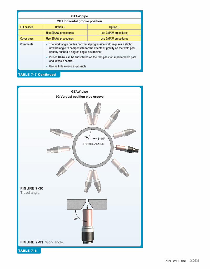
Table 7-7 Continued
gtaW pipe
2g Horizontal groove position
Fill passes Option 2 Option 3
Use SMAW procedures Use GMAW procedures
Cover pass Use SMAW procedures Use GMAW procedures
Comments ◾◾ The work angle on this horizontal progression weld requires a slight upward angle to compensate for the effects of gravity on the weld pool. Usually about a 5 degree angle is sufficient.
◾◾ Pulsed GTAW can be substituted on the root pass for superior weld pool and keyhole control.
◾◾ Use as little weave as possible
gtaW pipe
5g vertical position pipe groove
5–15°
TRAVEL ANGLE
FIgure 7-30 Travel angle.
90°
FIgure 7-31 Work angle.
Table 7-8
M07_HOFF6344_02_SE_C07.indd 233 09/01/16 5:43 pm
234 CHaPTeR 7
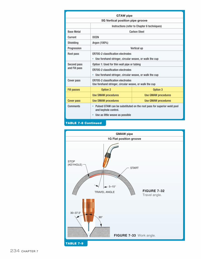
Table 7-8 Continued
gtaW pipe
5g vertical position pipe groove
Instructions (refer to Chapter 6 techniques)
Base Metal Carbon Steel
Current DCEN
Shielding Argon (100%)
Progression Vertical up
Root pass ER70S-2 classification electrodes◾◾ Use forehand stringer, circular weave, or walk the cup
Second passand Fill pass
Option 1: Used for thin wall pipe or tubing
ER70S-2 classification electrodes◾◾ Use forehand stringer, circular weave, or walk the cup
Cover pass ER70S-2 classification electrodesUse forehand stringer, circular weave, or walk the cup
Fill passes Option 2 Option 3
Use SMAW procedures Use GMAW procedures
Cover pass Use SMAW procedures Use GMAW procedures
Comments ◾◾ Pulsed GTAW can be substituted on the root pass for superior weld pool and keyhole control.
◾◾ Use as little weave as possible
gmaW pipe
1g Flat position groove
5–15°
TRAVEL ANGLE
START
STOP(KEYHOLE)
FIgure 7-32 Travel angle.
30–37.5°
90°
FIgure 7-33 Work angle.
Table 7-9
M07_HOFF6344_02_SE_C07.indd 234 09/01/16 5:43 pm

PIPe WelDInG 235
Table 7-9 Continued
gmaW pipe
1g Flat position groove
Instructions (refer to Chapter 4 techniques)
Base Metal Carbon Steel
Current DCEP
Shielding Argon/carbon dioxide
Electrode classification ER70S-6 or ER70S-3
Root pass Backhand stringer or forehand stringer bead, or weave
Fill passes Backhand stringer or forehand stringer bead, or weave
Cover pass Backhand stringer or forehand stringer bead, or weave
Comments Use as little weave as possible
gmaW pipe
2g Horizontal position groove
5–15°
TRAVEL ANGLE
FIgure 7-34 Travel angle.
Table 7-10
M07_HOFF6344_02_SE_C07.indd 235 09/01/16 5:43 pm

236 CHaPTeR 7
Table 7-10 Continued
gmaW pipe
2g Horizontal position groove
Instructions (refer to Chapter 4 techniques)
Base Metal Carbon Steel
Current DCEP
Shielding Argon/carbon dioxide
Electrode classification ER70S-6 or ER70S-3
Root pass Backhand stringer or forehand stringer bead, or weave
Fill passes Backhand stringer or forehand stringer bead, or weave
Cover pass Backhand stringer or forehand stringer bead, or weave
Comments ◾◾ The work angle on this horizontal progression weld requires a slight upward angle to compensate for the effects of gravity on the weld pool. Usually about a 5 degree angle is sufficient.
◾◾ Use as little weave as possible
5°
FIgure 7-35 Work angle.
gmaW pipe
5g vertical groove position
5–15°
TRAVEL ANGLET
5–15°
ANGLE
FIgure 7-36 Travel angle.
Table 7-11
M07_HOFF6344_02_SE_C07.indd 236 09/01/16 5:43 pm

PIPe WelDInG 237
Table 7-11 Continued
gmaW pipe
5g vertical groove position
Instructions (refer to Chapter 4 techniques)
Base Metal Carbon Steel
Current DCEP
Shielding Argon/carbon dioxide
Electrode classification ER70S-6 or ER70S-3
Progression Vertical down
Root pass Backhand stringer or weave
Fill passes Backhand stringer or weave
Cover pass Backhand stringer or weave
Progression Vertical up
Root pass Root pass only vertical down–backhand stringer or weave
Fill passes Forehand stringer bead, or tight weave
Cover pass Forehand stringer bead, or tight weave
Comments Use as little weave as possible
30–37.5°
90°
FIgure 7-37 Work angle.
gtaW pipe
1g Flat groove position
CONSUMABLE INSERT
START
STOP
5–15°
TRAVEL ANGLE
FIgure 7-38 Travel angle.
Table 7-12
M07_HOFF6344_02_SE_C07.indd 237 09/01/16 5:43 pm

238 CHaPTeR 7
Table 7-12 Continued
gtaW pipe
1g Flat groove position
Instructions (refer to Chapter 6 techniques)
Base metal Stainless steel—304L
Current DCEN
Shielding Argon (100%)
Electrode EWCe-2, sharpen to point
Insert Stainless steel—304L
Filler metal ER308L
Root pass Use forehand stringer, circular weave, or walk the cup
Fill passes Use forehand stringer, circular weave, or walk the cup
Cover pass Use forehand stringer, circular weave, or walk the cup
Comments Back purge with argon or nitrogen, use as little weave as possible
30–37.5°
90°
gmaW pipe
1g Flat groove position
5–15°
TRAVEL ANGLE
STARTSTOP
FIgure 7-40 Travel angle.
Table 7-13
FIgure 7-39 Work angle.
M07_HOFF6344_02_SE_C07.indd 238 09/01/16 5:43 pm

PIPe WelDInG 239
chapter questIons/assIgnMents
MultIple choIces
1. Which welding position includes welding in flat, horizon-tal, and overhead progressions?a. 1Gb. 2Gc. 4Gd. 5G
2. Which electrodes classification is commonly used for welding the root pass on carbon steel pipe?a. eXX10b. eXX12c. eXX14d. eXX18
3. What is the work angle for 2G pipe?a. 5 degreesb. 37 ½ degreesc. 45 degreesd. 60 degrees
4. Which process works well with thin walled pipe in the ver-tical down position?a. GTaWb. FCaWc. GMaWd. SMaW
5. Which of the following is used to float out any difficult to remove slag particles?a. Root passb. Hot passc. Fill passd. Cap pass
Table 7-13 Continued
gmaW pipe
1g Flat groove position
Instructions (refer to Chapter 4 techniques)
Base metal Aluminum -6061
Current DCEP
Shielding Argon (100%)
Electrode ER4043
Root pass Use forehand stringer
Fill passes Use forehand stringer
Cap pass Use forehand stringer
Comments Use GTAW to Tack/fit-up
30–37.5°
90°
FIgure 7-41 Work angle.
M07_HOFF6344_02_SE_C07.indd 239 09/01/16 5:43 pm

240 CHaPTeR 7
true/ False
17. The cap pass should be as wide as possible.
18. The use of argon shielding without fluxes, and with the aid of remote amperage technology allow great degree of arc control for open root welding.
19. Tack welds are an integral part of the weld assembly.
20. If the keyhole closes fusion will be complete.
21. Four tack welds are usually sufficient for small diameter pipe.
FIll In the Blank
short answer
6. Rather than welding in one linear direction the welder must constantly adjust the welding __________________ to account for the curvature of the pipe.
7. The __________________ is the initial pass deposited after the pipe is fit-up and tack welded together.
8. For larger __________________ diameters used with __________________ and GTaW the included angle may be as much as 70 degrees
9. Tack welds must have __________________ joint penetra-tion, and be large enough hold the pipe rigidly in place to withstand__________________ and __________________ forces introduced during placement of the root pass.
10. If the inside edges of the pipe are not __________________ it will be difficult to maintain __________________ joint pen-etration through the full length of the weld.
11. Mill scale, varnish, paint, rust, or other contaminants must be removed prior to joint fit-up to a distance of how much?
12. What will a properly shaped and sized keyhole do?
13. Where does arc initiation need to take place for all weld starts?
14. How are pipe pieces kept in alignment prior to tack welding?
15. Why must the root pass is completed be thoroughly cleaned?
16. How much space is left to fill in the groove after fill passes are complete?
M07_HOFF6344_02_SE_C07.indd 240 09/01/16 5:43 pm