storage area network operation - amazon web services · storage area network extension design and...
TRANSCRIPT


Storage Area Network Extension Design and
OperationMark Allen - Manager Storage Technical Marketing
BRKSAN-2449

• SAN Extension Deployment Challenges
• Principles of SAN Extension Design
• SAN Extension Network Solution Options
• SAN Extension Advanced Features
• Operation / Troubleshooting Reference
Agenda
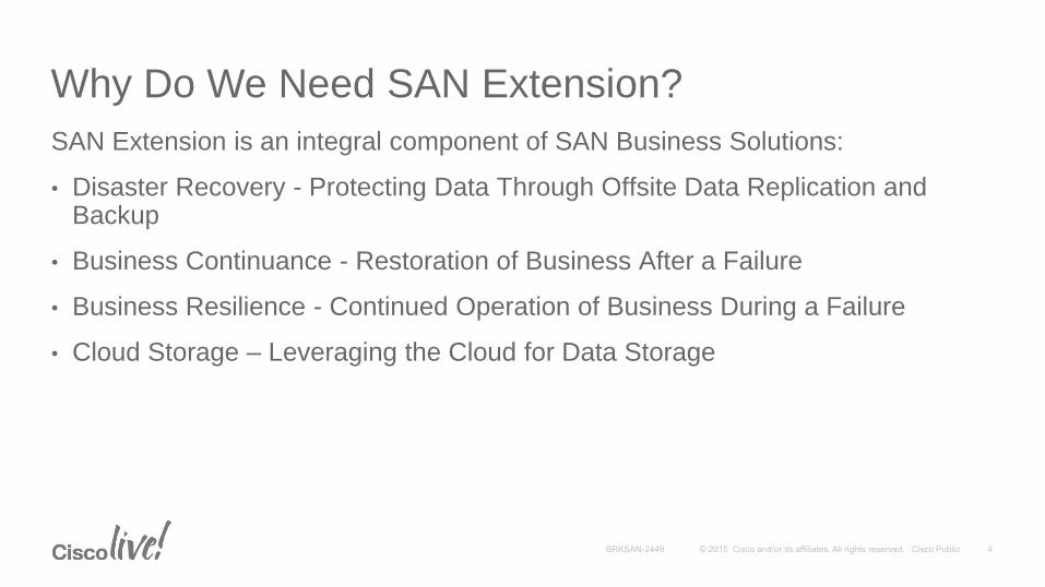
Why Do We Need SAN Extension?
SAN Extension is an integral component of SAN Business Solutions:
• Disaster Recovery - Protecting Data Through Offsite Data Replication and Backup
• Business Continuance - Restoration of Business After a Failure
• Business Resilience - Continued Operation of Business During a Failure
• Cloud Storage – Leveraging the Cloud for Data Storage
SAN Extension Deployment Challenges

Recovery Point and Recovery Time
Time
Disaster
Strikes
How Long to Recover?How Far Back?
Last Backup or
Point Where Data
in Usable State
Systems Recovered
and Operational
Recovery
Time
Recovery
Point
Smaller RPO/RTO• Higher $$$
• Replication
• Hot standby systems
Larger RPO/RTO• Lower $$$
• Tape backup/restore
• Cold standby system
Meeting Business Objectives

How Far is Enough?
Disasters are characterized by their impact
Local, metropolitan, regional, global
Fire, flood, earthquake, attack
Fundamental Question: Is the recovery / backup site within the threat radius you’re protecting against?
Local
1–2 km
Metro
< 50km
Regional
< 400km
Primary
Data Center
Secondary
Data CenterDR Site
Global

Is Your Data Safe?
Data Protection Also Includes Security
• Who has access to your data and your data network?
• Network Access Control (NAC)
• Role Based Access Control (RBAC)
• How is your data being protected on the network?
• Link Encryption on the network
• How do you protect your data media?
• Media encryption
Reference: CiscoLive! 2010 - BRKSAN-2892: Implementing Security for SANs
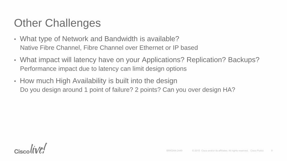
Other Challenges
• What type of Network and Bandwidth is available?
Native Fibre Channel, Fibre Channel over Ethernet or IP based
• What impact will latency have on your Applications? Replication? Backups?
Performance impact due to latency can limit design options
• How much High Availability is built into the design
Do you design around 1 point of failure? 2 points? Can you over design HA?

Adding It All Up
• Data is the most valuable commodity in the data center
• Businesses require comprehensive business plans for Business Continuity (BC) and Disaster Recovery (DR)
• SAN Extension is the foundation to a successful BC/DR plan

Principles of SAN Extension Design

Typical SAN Design
• Servers with two Fibre Channel connections to storage arrays for high availability
• Use of multipath software is required in dual fabric host design
• SAN extension fabrics typically separated from host access fabrics
• Replication fabric requirements vary by replication method deployed
“A” Fabrics
Access
Fabrics
“B” Fabrics
Site 2
Site 1
Replication
Fabrics
Replication
Fabrics
DC
Interconnect
Network
BRKSAN-2883 - Advanced Storage Area Network Design
Thursday 13:00-14:30 – Room 25AB Upper Level

Basic HA SAN Extension Network
High-Availability Replication Design:
• Conventional approach is dual fabrics (E.g., yellow VSAN and orange VSAN) over distance
• “Client protection”—arrays provide protection against failures in either fabric
• May be augmented with additional “network protection” via portchannels and/or optical protection schemes
“A” Fabrics
Access
VSANs
“B” Fabrics
Replication
VSANs
Site 2
Site 1
Replication
VSANs
DC
Interconnect
Network

SAN Extension Design: Adding Link HA Portchannels Increase Resilience for High-Availability with FC, FCoE or FCIP Links
• Appears as a single logical link (up to sixteen member links)
• Protecting the fabric from network failure
• Route portchannel member links over diverse geographic paths
• Load balancing on SRCID/DESTID or SRCID/DESTID/OXID basis (unidirectional per VSAN)
• SCSI exchange is smallest atomic unit, so frame order kept intact
“A” Fabrics
Access
VSANs
“B” Fabrics
Replication
VSANs
Site 2
Site 1
Replication
VSANs
Portchannels

SAN Extension Network Solution Options:
Native Fibre Channel

Limited by Optics (Power Budget)
SAN Extension Technology Options
Dark Fiber1/2/4/8/10/16G FC, 10GE FCoE
CWDM1/2/4/8G FC, 10GE FCoE
DWDM1/2/4/8G FC, 10GE FCoE
Data
Center Campus Metro Regional National
Increasing Distance
Sync
Sync
Async (WAN)MDS9000 FCIPGE, 10GE
Limited by Optics (Power Budget)
Limited by BB_Credits
Op
tic
al
IP Sync (Metro Eth)
Global
Sync

Dark Fibre
• Single 1/2/4/8/10/16 Gbps FC link per fiber pair
• SW (850nm) over 62.5/125µm multimode
• SW (850nm) over 50/125µm multimode (OM2, OM3 or OM4)
• LW (1310nm) over 9/125µm single mode
• Client protection only; Upper Layer Protocol (ULP), either SAN or application, responsible for failover protection
Diverse
Paths—
Multiple
Fiber Pairs
Each Path
Portchannel 2-
16 1/2/4/8/10
Gbps FC Over
Two Diverse
Paths
Distance
Based on
Fiber Type,
Optic Type,
Link Speed

Coarse Wavelength Division Multiplexing (CWDM)
• 8-channel xWDM technology using 20nm spacing (cf DWDM at <1nm spacing)
• 1470, 1490, 1510, 1530, 1550, 1570, 1590, 1610nm
• “Colored” CWDM SFPs (or GBICs) used in FC switches (no transponder required)
• Optical multiplexing done in CWDM OADM (optical add/drop multiplexer)
• Passive (unpowered) device; just mirrors and prisms
• Up to 30dB power budget (36dB typical) on Single Mode Fiber (SMF)
• 1 / 2 Gb - ~100km point-to-point or ~40km ring
• 4 / 8 Gb - ~40km point-to-point or ~20km ring
• 1/2/4/8 Gigabit Fibre Channel and 1 Gigabit Ethernet support
1470nm
1510nm
1550nm
1590nm
OADM
Mux/Demux 1490nm
1530nm
1570nm
1610nm

2-Site CWDM Storage Network
• HA resilience against fiber cut—“client” protection
• 4-member portchannel - 2 x 2 diverse paths
• Portchannel appears as single logical link
• E_Port or TE_Port for carriage of VSANs
• Load balance by src/dst /oxid (or src/dst if required)
• Fiber cut will halve capacity from 64Gbps to 32Gbps but not alter fabric topology - no FSPF change
• MUX-8 would double capacity or leave spare wavelengths for GigE channels
MUX-4MUX-4
MUX-4MUX-4
Diverse
Paths:
One Fiber
Pair Each
Path
Portchannel
2-16 1/2/4/8
Gbps FC Over
Two Diverse
Paths
8 Gbps
CWDM
SFPs

CWDM Optics Without Multiplexor
• CWDM Optics do not require MUX
• If dark fiber available, can be used like typical SFPs
• Can use different wavelengths or the same wavelengths on all interfaces
• Use of optical attenuators may be required for shorter distance fiber runs
• Optical power meter used to measure signal strength
Portchannel
4 x 8 Gbps
4 fibre
paths
between
each
switch
8 Gbps
CWDM
SFPs—
same
wavelength
8 Gbps
CWDM
SFPs—
different
wavelengths

Dense Wavelength Division Multiplexing (DWDM)
• Higher density xWDM technology compared with CWDM
32 lambdas or channels in the narrow band around 1550nm at 100GHz spacing (0.8nm)
• Erbium-Doped Fiber Amplifiers (EDFA) allow for longer distances than CWDM
• Carriage of 1, 2, 4, 8, 10 or 16 Gbps FC, FICON, GigE, 10GigE, ESCON, IBM GDPS
• Data center to data center
• Multiple Protection options: client, splitter, or line card

DWDM Protection Alternatives for Storage
• Single transponder required
• Protects against fiber breaks
• Failover causes loss of light (and fabric change if only link)
• Dual transponders required
More expensive than splitter-based protection
• Transmits over both circuits, but only one accepted
Optical Splitter Protection
Line card or Y-Cable Protection
Working Lambda
Protected Lambda
Optical
Splitter
Protected Lambda
Y-cable Working Lambda

DWDM Optics Integrated in MDS 9000
MDS Transponder ROADM
Traditional DWDM FC and DWDM -MDS w/ Integrated DWDM Optics
DW
DM
I/F
MDS ROADM
DWDM SFP
Support for 1/2/4G FC
No optical transponder required
DWDM sfp in MDS connects directly to OADM module of ONS 100 Ghz products
32 wavelengths mapping to ITU channels 21-24, 26-29, 31-34, 36-39, 41-44, 46-49, 51-54 and 56-59

DWDM HA Storage Network Topology (1)
• Client protection recommended
• Fabric and application responsible for failover recovery
• Portchannel provides resilience
• Portchannel members follow diverse paths
• Single fiber cut will not affect fabric (no RSCNs, etc.)
• Loss of path reduces bandwidth of both “A” and “B” fabrics by 50%
• Use “SID/DID/OXID” hash for load balancing (rather than “SID/DID” per exchange) for each extended VSAN
DWDM
Ring
Portchannel
2-16 1/2/4/8/10
Gbps FC Over
Two Diverse
Paths
Diverse
Paths – One
Fiber Pair
Each Path

DWDM HA Storage Network Topology (2)
• Client protection recommended
• Fabric and application responsible for failover recovery
• Portchannel provides resilience
• Portchannel members follow diverse paths
• Single fiber cut will not affect fabric (no RSCNs, etc.)
• Loss of path reduces bandwidth of only one fabric by 50%
• Use “SID/DID/OXID” hash for load balancing (rather than “SID/DID” per exchange) for each extended VSAN
DWDM
RingDWDM
Ring
Portchannel
2-16 1/2/4/8/10
Gbps FC Over
Two Diverse
Paths
Diverse
Paths – One
Fiber Pair
Each Path
Optics Information
• For complete information on MDS optics, refer to the Cisco MDS 9000 Family Pluggable Transceivers Data Sheet at:
http://www.cisco.com/c/en/us/products/collateral/storage-networking/mds-9000-series-multilayer-switches/product_data_sheet09186a00801bc698.pdf
Reference
SAN Extension Network Solution Options:
Fibre Channel over IP (FCIP)

FCIP: Fibre Channel over IP
FCIP is a standard from the IETF IP Storage WG for Linking Fibre Channel SANs over IP (RFCs 3821 and 3643)
• Point-to-point tunnel between FCIP link end-points
• Creates one logical FC fabric with single FSPF routing domain
FC SANFC SAN
IP Network
FCIP Tunnel

FCIP Frame Detail
• Max Fibre Channel frame is 2148 bytes plus optional extras
• FCIP will segment and reassemble FC frames if MTU too small (TCP payload on second or subsequent packets)
• Jumbo frames may increase performance
• IP MTU of 2300 avoids splitting of TCP frames
FCIP
Header
Ethernet
Header
IP
Header
TCP
Header
TCP
OptsFC Frame
Ethernet
CRC32
14 20 20 12 28 4
94
EISL
Hdr
SO
F
4 8
Max 2148 (E_Port) + EISL and Opt Headers
FCIP Overhead for
Ethernet Frames:
94 Byte Header + 4
Byte CRC = 98 Bytes
EISL and Optional
Headers
If TE_Port, then 8 Bytes
Added to FC Frame (After
SOF) for VSAN Routing
opt
Hdr
0-16
Differences Between Storage and TCP Networks
• Storage traffic:
• Quite bursty
• Latency sensitive (sync apps)
• Requires high, instantaneous throughput
• Traditional TCP:
• Tries to be network sociable
• Tries to avoid congestion (overrunning downstream routers)
• Backs off when congestion detected
• Slow to ramp up over long links (slow start and congestion avoidance)
Can these differences be resolved?

MDS FCIP TCP Behavior
• Designed to reduce probability of drops
• Bursts are controlled through per flow shaping and congestion window control - less likely to overrun routers
• Increased resilience to drops
• Uses SACK, fast retransmit and shaping
• Aggressive slow start mechanism
• Initial rate controlled by “min-available-bandwidth”
• Max rate controlled by “max-bandwidth”
Differences with Normal TCP:
When congestion occurs with other conventional TCP traffic, FCIP is more aggressive during recovery (“bullying” the other traffic)
Aggression is proportional to the min-available-bandwidth configuration

Frame Buffering: FCIP and FC
• FCIP presents a lower bandwidth pipe (if WAN link)
• Drain rate (send rate) depends upon bandwidth and congestion
• Slow ramp up of traditional TCP can cause FC frame expiry in some conditions
• Mixture of slow link (e.g., <DS3/E3; retransmissions, many sources, big buffers)
BB_Credit
Flow Control
BB_Credit
Flow Control
Traffic Flow
FC Receive Buffers FCIP Receive Buffers
TCP Windowing Flow Control
GigE Slower
WAN LinkGigE
Backlog Here if Queue Can’t Drain Due To:
Slow WAN link and long RTT
Packet loss and retransmissions
Many sources (only one shown)
Buffer too big

FCIP TCP Packet Shaping: MDS9000
• Shaper sends at a rate consumable by the downstream path
• Immediately sends at “minimum-bandwidth” rate (avoids early stages of traditional slow start)
• Ramps up to “maximum-bandwidth” rate (using usual slow start and congestion avoidance methods)
• Requirements for shaper to engage:
• Min-available-bandwidth > 1/20 max-bandwidth
• SACK (Selective Ack) must be enabled (default)
Traffic Flow
DestinationSource
Gigabit
Ethernet
Gigabit
Ethernet45Mbps
Source Sends
Packets at rate
Consumable by
Downstream Path
Shaping Avoids Congestion at This Point
Interpacket Gap to Accommodate Slow
Downstream Link (E.G 45mbps)

0
5
10
15
20
25
30
35
40
45
1 2 3 4 5 6 7 8 9 10 11 12 13 14 15 16 17 18 19 20 21 22 23 24 25 26 27 28 29 30 31 32
Exponential “Slow Start”
(increase 2x pkts per RTT)
LossLoss
# Round Trip Times (RTT)
Pa
cke
ts S
en
t pe
r Ro
un
d T
rip Low Throughput During
This Period
MDS vs. TCP BehaviorLinear “Congestion
Avoidance”
(MDS +2/cwnd per ack)
(TCP +1/cwnd per ack)
Congestion Window Halved on
Packet Loss; Retransmission
Signals Congestion…Slow Start
Threshold Adjusted
0
200
400
600
800
1000
1200
1400
1 2 3 4 5 6 7 8 9 10 11 12 13 14 15 16 17 18 19 20 21 22 23 24 25 26 27 28 29 30 31 32
# Round Trip Times (RTT)
Aggre
gate
Packets
Sent
MDS vs. TCP Behavior
LossLoss
TCP – 714 packets
sent
∆ 41%
∆ 50%
∆ 65%
MDS - 1181 packets
sent

Fibre Channel over IP (FCIP) Design
• Same port channeling and VSAN trunking rules apply as with FC links
• Portchannel individual FCIP links to separate Ethernet switches/routers
• Each WAN link carries two FCIP tunnels
• Load balancing on SRCID/DESTID or SRCID/DESTID/OXID basis (unidirectionally per VSAN)
• Certain replication protocols require SRCID/DESTID load balancing:FICON, IBM PPRC, HP CA-EVA
Portchannel
2-16 FCIP
Interfaces
Over Diverse
Paths
Diverse
Network
Paths

Configuring FCIP
feature fcip
interface GigabitEthernet 1/1ip address 10.10.100.1 255.255.255.0
fcip profile 11ip address 10.10.100.1tcp max-bandwidth-mbps 1000 min-available-bw-mbps 950 round-trip-time-ms 10
interface fcip 11switchport trunk mode offuse profile 11peer-info ipaddr 10.10.100.2
Reference
feature fcip
interface GigabitEthernet 1/1ip address 10.10.100.2 255.255.255.0
fcip profile 11ip address 10.10.100.2tcp max-bandwidth-mbps 1000 min-available-bw-mbps 950 round-trip-time-ms 10
interface fcip 11switchport trunk mode offuse profile 11peer-info ipaddr 10.10.100.1
Define Local GE interface
Associate
profile to FCIP
interface
Define maximum and minimum
bandwidth and network latency
Associate Local GE IP address with
profile
Identify remote
FCIP peer
int fcip 11 int fcip 11GigE1/1 GigE1/1

Configuring FCIP (IPv6)
feature fcip
interface IPStorage 1/1ipv6 enableipv6 address 92:50::01/32
fcip profile 250ip address 92:50::01tcp max-bandwidth-mbps 1000 min-available-bw-mbps 950 round-trip-time-ms 5
interface fcip 250switchport trunk mode offuse profile 250peer-info ipaddr 92:50::02
Reference
feature fcip
interface GigabitEthernet 1/1ipv6 enableipv6 address 92:50::02/32
fcip profile 250ip address 92:50::02tcp max-bandwidth-mbps 1000 min-available-bw-mbps 950 round-trip-time-ms 5
interface fcip 250switchport trunk mode offuse profile 250peer-info ipaddr 92:50::01
Define Local GE interface
Associate
profile to FCIP
interface
Define maximum and minimum
bandwidth and network latency
Associate Local GE IPv6 address with
profile
Identify remote
FCIP peer
int fcip 250 int fcip 250IPS1/1 GigE1/1

Configuring 2 FCIP interfaces on a single GE port• Sometimes it is desirable to configure two (or more) FCIP tunnels on the same Ethernet port
Different destinations from same port (hub and spoke design)
Increased performance with multiple tunnels
• Using tcp port other than 3225 (default) allows sharing same Ethernet interface and IP address
Configure non-default fcip profiles and interfaces prior to configuring interfaces using default ports
feature fcip
interface GigabitEthernet 1/1ip address 10.10.100.1 255.255.255.0
fcip profile 12port 3226ip address 10.10.100.1tcp max-bandwidth-mbps 500 min-available-bw-mbps 450 round-trip-time-ms 10
fcip profile 11ip address 10.10.100.1tcp max-bandwidth-mbps 500 min-available-bw-mbps 450 round-trip-time-ms 10
interface fcip 12switchport trunk mode offuse profile 12peer-info ipaddr 10.10.100.2 port 3226
interface fcip 11switchport trunk mode offuse profile 11peer-info ipaddr 10.10.100.2
Reference
feature fcip
interface GigabitEthernet 1/1ip address 10.10.100.2 255.255.255.0
fcip profile 12port 3226ip address 10.10.100.2tcp max-bandwidth-mbps 500 min-available-bw-mbps 450 round-trip-time-ms 10
fcip profile 11ip address 10.10.100.2tcp max-bandwidth-mbps 500 min-available-bw-mbps 450 round-trip-time-ms 10
interface fcip 12switchport trunk mode offuse profile 12peer-info ipaddr 10.10.100.1 port 3226
interface fcip 11switchport trunk mode offuse profile 11peer-info ipaddr 10.10.100.1
int fcip 12 int fcip 12
int fcip 11 int fcip 11
GigE1/1 GigE1/1
Configure non-default profiles first
FCIP Differences between platforms
• Current MDS FCIP platforms
• MDS 9222i, MSM 18/4 and SSN-16 FCIP platforms with 1GE ports
• MDS 9250i FCIP platform with 1/10GE ports
• 9250i FCIP ports backwards compatible with previous MDS FCIP platforms
• 9250i interface name changed from interface gigabitethernet <slot/port> to interface IPStorage <slot/port>
• The FCIP profile “tcp max-bandwidth” and “min-bandwidth” maximum value changes from 1000 Mbps (1000000 Kbps) to 5000 Mbps (5000000 Kbps)• When connecting 9250i to previous FCIP platforms, do not exceed 1000 Mbps
• FCIP tunnels on 9250i with greater than 1000 Mbps values configured require changing the default FCIP interface “tcp-connections” from 2 to 5• Default remains 2 tcp connections (1 Control, 1 Data) for backwards compatibility
• 9250i and 10GE ports require more tcp connections (1 Control, 4 Data)
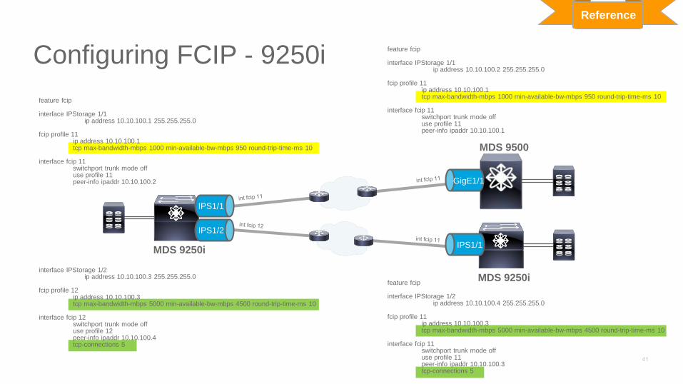
Configuring FCIP - 9250i
Reference
IPS1/1
GigE1/1
IPS1/1
IPS1/2
MDS 9250i
MDS 9250i
MDS 9500
feature fcip
interface IPStorage 1/1ip address 10.10.100.1 255.255.255.0
fcip profile 11ip address 10.10.100.1tcp max-bandwidth-mbps 1000 min-available-bw-mbps 950 round-trip-time-ms 10
interface fcip 11switchport trunk mode offuse profile 11peer-info ipaddr 10.10.100.2
interface IPStorage 1/2ip address 10.10.100.3 255.255.255.0
fcip profile 12ip address 10.10.100.3tcp max-bandwidth-mbps 5000 min-available-bw-mbps 4500 round-trip-time-ms 10
interface fcip 12switchport trunk mode offuse profile 12peer-info ipaddr 10.10.100.4tcp-connections 5
feature fcip
interface IPStorage 1/1ip address 10.10.100.2 255.255.255.0
fcip profile 11ip address 10.10.100.1tcp max-bandwidth-mbps 1000 min-available-bw-mbps 950 round-trip-time-ms 10
interface fcip 11switchport trunk mode offuse profile 11peer-info ipaddr 10.10.100.1
feature fcip
interface IPStorage 1/2ip address 10.10.100.4 255.255.255.0
fcip profile 11ip address 10.10.100.3tcp max-bandwidth-mbps 5000 min-available-bw-mbps 4500 round-trip-time-ms 10
interface fcip 11switchport trunk mode offuse profile 11peer-info ipaddr 10.10.100.3tcp-connections 5
SAN Extension Network Solution Options:
Fibre Channel over Ethernet(FCoE)

SAN Extension Solutions with FCoE
• Typical FCoE SAN Extension deployment rely on FC or FCIP to transport data over distance
• Native FCoE for SAN Extension is an option if lossless Ethernet transport is available between Data Centers
• FCoE SAN extension solutions face similar issues as native FC solutions
Optics – What distance can native 10GE optics cover?
Buffering – How long of a link can be filled with FCoE traffic?
Topologies – How does use of Shared or Dedicated FCoE ISLs affect design?

FCoE Flow ControlIEEE 802.1Qbb Priority Flow Control
• VLAN Tag enables 8 priorities for Ethernet traffic
• PFC enables Flow Control on a Per-Priority basis using PAUSE frames (IEEE 802.1p)
• Receiving device/switch sends Pause frame when receiving buffer passes threshold
• Distance support is determined by how much buffer is available to absorb data in flight after Pause frame sent
Ethernet Wire
FCoE

FCoE Flow Control and Long Distance FCoE
For long distance FCoE, receiving switch Ingress Buffer must be large enough to absorb all packets in flight from the time the Pause frame is sent to the to time the Pause Frame is received
• A 10GE, 50 km link can hold ~300 frames
• That means 600+ frames could be either in flight or will be transmitted by the time the receiver detects buffer congestion and sends a Pause frame to the time the Pause frame is received and the sender stops transmitting
Frame Frame Frame Frame Frame
Pause
Frame
Frame
Frame
Frame
Frame
Frame
Frame
Frame
Egress Buffer Ingress Buffer
Buffer Threshold

FCoE Extension Options
• Different Platforms have different buffer capabilities
• Distance supported is limited to the least common denominator switch
From / To Nexus 5500 Nexus 6000Nexus 7000
F1 line card
Nexus 7000
F2 line cardMDS 9500 MDS 9700 MDS 9250i
Nexus 5500 3 km 3 km 3 km 3 km 3 km 3 km 3 km
Nexus 6000 3 km 3 km 3 km 3 km 3 km 3 km 3 km
Nexus 7000
F1 line card3 km 3 km 5 km 5 km 5 km 5 km 5 km
Nexus 7000
F2 line card3 km 3 km 5 km 70 km 5 km 70 km 70 km
MDS 9500 3 km 3 km 5 km 5 km 5 km 5 km 5 km
MDS 9700 3 km 3 km 5 km 70 km 5 km 70 km 70 km
MDS 9250i 3 km 3 km 5 km 70 km 5 km 70 km 70 km
Reference
46

Native FCoE SAN Extension
• FCoE SAN Extension uses same design principles as FC or FCIP
• Separate VLANs/VSANs for Host and replication traffic
• Load Balancing using SID/DID/OXID
• Data Center Interconnect must be FCoE DCB network
FC
DCB/FCoE
Ethernet
FCoE
Nexus
Nexus
Portchannel
2-16 FCoE
Interfaces
Over Diverse
Paths

FCoE SAN with FC or FCIP Extension
• FCoE Attached disk replication uses FC or FCIP transport network
• SAN Extension design criteria based on FC or FCIP interconnect network
FC
DCB/FCoE
Ethernet
FCoE
Nexus
Nexus
MDS 9700
MDS 9250i
MDS 9700
MDS 9250i
Portchannel
2-16 FCoE
Interfaces
Over Diverse
Paths
Portchannel
2-16 FCIP
Interfaces
Over Diverse
Paths
Portchannel
2-16 FC
Interfaces
Over Diverse
Paths
SAN Extension Advanced Features
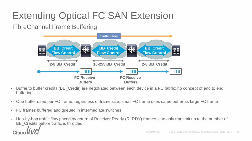
Extending Optical FC SAN Extension
• Buffer to buffer credits (BB_Credit) are negotiated between each device in a FC fabric; no concept of end to end buffering
• One buffer used per FC frame, regardless of frame size; small FC frame uses same buffer as large FC frame
• FC frames buffered and queued in intermediate switches
• Hop-by-hop traffic flow paced by return of Receiver Ready (R_RDY) frames; can only transmit up to the number of BB_Credits before traffic is throttled
FibreChannel Frame Buffering
FC Receive
Buffers
Traffic Flow
BB_Credit
Flow Control
FC Receive
Buffers
2-8 BB_Credit 16-255 BB_Credit 2-8 BB_Credit
BB_Credit
Flow Control
BB_Credit
Flow Control

Extending Optical FC SAN Extension
• BB_Credits are used to ensure enough FC frames in flight
• A full (2112 byte) FC frame ranges from 1/8 km long (16 Gbps FC) to 2 km long (1 Gbps FC)
• As distance increases or frame size decreases, the number of available BB_Credits required increases as well
• Insufficient BB_Credits will throttle performance - no data will be transmitted until R_RDY is returned
BB_Credits and Distance
Frame Size 1 Gbps 2 Gbps 4 Gbps 8 Gbps 10 Gbps 16 Gbps
512 Bytes 2 BB/km 4 BB/km 8 BB/km 16 BB/km 24 BB/km 32 BB/km
1024 Bytes 1 BB/km 2 BB/km 4 BB/km 8 BB/km 12 BB/km 16 BB/km
2112 Bytes .5 BB/km 1 BB/km 2 BB/km 4 BB/km 6 BB/km 8 BB/km

Configuring Extended BB Credits
Configuring MDS to support 500km at 16G over a DWDM Network
MDS9710-A # configure terminal
Enter configuration commands, one per line. End with CNTL/Z.
MDS9710-A(config)# feature fcrxbbcredit extended
MDS9710-A(config)# interface fc 5/1
MDS9710-A(config-if)# switchport fcrxbbcredit extended 4000
MDS9710-A(config-if)# end
MDS9710-A# sh int fc1/1
fc1/1 is trunking
Hardware is Fibre Channel, SFP is short wave laser w/o OFC (SN)
Port WWN is 20:01:54:7f:ee:ea:55:00
Peer port WWN is 20:01:8c:60:4f:54:51:00
Admin port mode is auto, trunk mode is on
snmp link state traps are enabled
Port mode is TE
Port vsan is 1
Speed is 16 Gbps
Rate mode is dedicated
Transmit B2B Credit is 500
Receive B2B Credit is 4000
B2B State Change Number is 14
Receive data field Size is 2112
Enable extended BB feature
Set BB credits (4000 required)
Verify BB credits set
Reference
FC1/1

Shared Dedicated
FX-Port
(Fixed)
FX-Port
(Default)
E-Port
(Default)
FX-Port /
E-Port
(Min-Max)
Extended
Credits
(Min-Max)
Speed
(Gbps)
Max Distance (1) (km)
Disable Ports for
Max Credits?
48 Port 2/4/8/1016 Gbps
Advanced Switching Module
(DS-X9448-768)
MDS 9396S
(DS-C9396S)
32 32 500 2-500 256-4095
2 4000
No
4 2000
8 1000
10 680
16 512
MDS 9250i
(DS-C9250i)
MDS 9148S
(DS-C9148S)
32 32 64 2-253 N/A
2 253
No
4 126
8 63
16 31
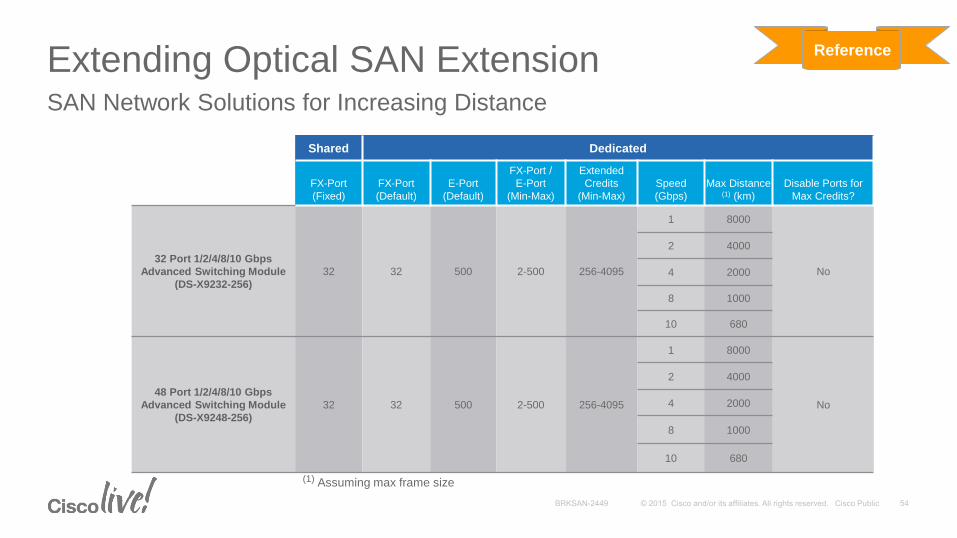
Extending Optical SAN ExtensionSAN Network Solutions for Increasing Distance
(1) Assuming max frame size
Reference
Shared Dedicated
FX-Port
(Fixed)
FX-Port
(Default)
E-Port
(Default)
FX-Port /
E-Port
(Min-Max)
Extended
Credits
(Min-Max)
Speed
(Gbps)
Max Distance (1) (km)
Disable Ports for
Max Credits?
32 Port 1/2/4/8/10 Gbps
Advanced Switching Module
(DS-X9232-256)
32 32 500 2-500 256-4095
1 8000
No
2 4000
4 2000
8 1000
10 680
48 Port 1/2/4/8/10 Gbps
Advanced Switching Module
(DS-X9248-256)
32 32 500 2-500 256-4095
1 8000
No
2 4000
4 2000
8 1000
10 680
Extending Optical SAN ExtensionSAN Network Solutions for Increasing Distance
(1) Assuming max frame size
Reference

Shared Dedicated
FX-Port
(Fixed)
FX-Port
(Default)
E-Port
(Default)
FX-Port /
E-Port
(Min-Max)
Extended
Credits
(Min-Max) Speed (Gbps)
Max Distance (1) (km)
Disable Ports for
Max Credits?
24 Port Performance 1/2/4/8-
Gbps
(DS-X9224-96)
32 32 500 2-500 256-40952
1 8190
No2 4095
4 2047
8 1023
48 Port Performance 1/2/4/8-
Gbps
(DS-X9248-96)
32 32 500 2-500 256-40952
1 8190
No2 4095
4 2047
8 1023
48 Port Host 1/2/4/8-Gbps
(DS-X9248-48)32 32 125 2-500 256-3,888
1 7666
No2 3888
4 1944
8 972
(1) Assuming max frame size
Extending Optical SAN ExtensionSAN Network Solutions for Increasing Distance
(2) Per port groups 1-4 and 5-8
Reference

Shared Dedicated
FX-Port
(Fixed)
FX-Port
(Default)
E-Port
(Default)
FX-Port /
E-Port
(Min-Max)
Extended
Credits
(Min-Max)
Speed
(Gbps)
Max Distance (1) (km)
Disable Ports for
Max Credits?
16 Port 1/2-Gbps
(DS-X9016)N/A 16 255 2-255 N/A
1 510No
2 255
32 Port 1/2-Gbps
(DS-X9032)12 12 12 12 N/A
1 24No
2 12
14/2 Port 1/2-Gbps
(DS-X9302-14K9)N/A 16 255 2-255 256-3,500
1 7,000 Disable 3 in a 4-port
group, if more than
2,400 per port9216i Fabric Switch 2 3,500
12 Port 1/2/4-Gbps
(DS-X9112)N/A 16 250
2-250 256-4,095
1 8,190
No
24 Port 1/2/4-Gbps
(DS-X9124)16 16 250 2 4,095
48 Port 1/2/4-Gbps
(DS-X9148)
MDS 9222i Fabric Switch
(DS-C9222i)
16 16 125 4 2,047
4 Port 10-Gbps
(DS-X9704)N/A 16 750 2-750 751-4,095 10 800 No
Extending Optical SAN ExtensionSAN Network Solutions for Increasing Distance
(1) Assuming max frame size
Reference

Shared Dedicated
FX-Port
(Fixed)
FX-Port
(Default)
E-Port
(Default)
FX-Port /
E-Port
(Min-Max)
Extended
Credits
(Min-Max)
Speed
(Gbps)
Max Distance (1) (km)
Disable Ports for
Max Credits?
MDS 9148 16 16 16 2-125 N/A
1 250
No2 125
4 62
8 31
MDS 9124 16 16 16 2-61 N/A
1 122
No2 61
4 30
Nexus 5500 N/A 16 16 2-240 N/A
1 480
No2 240
4 120
8 60
Extending Optical SAN Extension
(1) Assuming max frame size
Reference
SAN Network Solutions for Increasing Distance

Interface Resiliency with Portchanneling
• Portchannels allow multiple FC, FCoE or FCIP interfaces to be aggregated into a single, logical interface
• Portchannels remains operational as long as one interface remains active
• Portchannels maintain bandwidth even when members interface go down and avoid FSPF re-calculations
• Up to 16 equal cost interfaces can be in a single port-channel
• Multiple Portchannels can be used in parallel if more than 16 interfaces are needed (FSPF load balances over multiple Portchannels)

Configuring PortchannelsReference
FCIP111
FCIP121
interface port-channel 25channel mode activeswitchport mode Eswitchport rate-mode dedicated
interface fc 1/1switchport mode Echannel-group 25 force
interface fc 8/48switchport mode Echannel-group 25 force
FC 1/1
FC 8/48
interface port-channel 1channel mode activeswitchport mode Eswitchport rate-mode dedicated
interface fcip111use-profile 111peer-info ipaddr 10.10.10.2switchport mode Echannel-group 1 force
interface fcip121use-profile 121peer-info ipaddr 10.10.20.2switchport mode Echannel-group 1 force
Portchannel number
only has local
significance, no
requirement to be
same on both sides
Associate interface
(FC, FCoE or FCIP) to
Port-Channel
FCIP111
FCIP121
FC 1/1
FC 8/48
FCIP Data Compression
• Compression used to increase link data capacity of FCIP interfaces or reduce consumed bandwidth
• Two compression modes available
• Auto – Optimizes Compression based on bandwidth and data rate
• Mode1 – Deflate based compression algorithm (low bandwidth)
• Mode2 – Deflate based compression algorithm (moderate bandwidth)
• Data Compressibility is data stream dependent
• All nulls or ones → high compression (>30:1)
• Random data (e.g., encrypted) → low compression (~1:1)
• “Typical” rate is around 4:1 (Gen 3 & 4), but may vary considerably
• Application throughput is the most important factor

Configuring FCIP Compression
Configure FCIP compression
mds9513-labD# configure terminalEnter configuration commands, one per line. End with CNTL/Z.mds9513-labD(config)# interface fcip 1mds9513-labD(config-if)# ip-compression auto
mds9513-labD# show interface fcip 1fcip1 is up
Hardware is GigabitEthernet..
IP Compression is enabled and set for auto.
Enable FCIP auto
mode compression –
must be same for both
sides of FCIP tunnel
mds9513-labD# show interface fcip 1 counters fcip100TCP Connection Information..
IP compression statistics22958 rxbytes
22958 rxbytes compressed, 0 rxbytes non-compressed
1.28 rx compression ratio34660 txbytes
20765 txbytes compressed, 4160 txbytes non-compressed
1.39 tx compression ratio20641 txbytes compressed using auto
Reference
FCIP1
GE 5/1

Link Layer Security
• Data Confidentiality requirements are part of business today
• Businesses need to ensure that data is not compromised while be transmitted between Data Centers
• FC TrustSec (FC) and IPSec (FCIP) used to secure data over ISLs between switches
Primary DC Secondary DC
IPNetwork
DWDM
Backup Site
Name: XYZSSN: 1234567890Amount: $123,456Status: Gold
@!$%!%!%!%%^&*&^%$#&%$#$%*!^@*%$*^^^^%$@*)%#*@(*$%%%%#@
Name: XYZSSN: 1234567890Amount: $123,456Status: Gold
@!$%!%!%!%%^&*&^%$#&%$#$%*!^@*%$*^^^^%$@*)%#*@(*$%%%%#@
Name: XYZSSN: 1234567890Amount: $123,456Status: Gold
FC TrustSec IPSec

Hardware-Based FC TrustSec Encryption
• Hardware-based FC wire rate performance on MDS 9300, 9500 and 9700
• Extension to standards-based FC-SP protocol to provide encryption of data
• DH-CHAP used for peer authentication
• Encryption: AES 128 bit key
Disk Replication Secured with FC Trust Sec
Primary DC Secondary DC
MAN

Configuring FC TrustSec
Basic steps for configuring FC TrustSec
1. Enable FCSP feature (requires Enterprise License)MDS9513# configure terminal
Enter configuration commands, one per line. End with CNTL/Z.
MDS9513(config)# feature fcsp
Reference
FC2/15
MDS9513
20:00:00:0d:ec:07:e8:c0

Configuring FC TrustSec
Basic Steps for Configuring FC TrustSec
2) Configure DHCHAP for switch MDS9513 with switch-wwn 20:00:00:0d:ec:07:e8:c0MDS9513(config)# fcsp dhchap password 7 fewhg123
MDS9513(config)# fcsp dhchap devicename 20:00:00:0d:ec:07:e8:c0 password cisco123
3) Create one or more Security Associations (SA)MDS9513(config)# fcsp esp sa 400
MDS9513(config-sa)# salt 0xDEADBEEF
MDS9513(config-sa)# key 0x112233445566778899
MDS9513(config-sa)# exit
Reference

Configuring FC TrustSec
Basic Steps for Configuring FC TrustSec
4) Shut down interfaceswitch(config)# interface fc2/15
switch(config-if)# shut
5) Configure fcsp feature on interfaceswitch(config-if)# fcsp on
6) Configure Encapsulating Security Protocol (ESP) settings on interfaceswitch(config-if)# fcsp esp manual
switch(config-if-esp)# ingress-sa 400
switch(config-if-esp)# egress-sa 400
switch(config-if-esp)# exit
7) Bring up interfaceswitch(config-if)# no shut
Full FC TrustSec configuration example using Fabric Manager and Device Manager at:
http://www.cisco.com/c/en/us/td/docs/switches/datacenter/mds9000/sw/6_2/configuration/guides/security/nx-os/sec_cli_6-x/fctrstsec.pdf
Reference

Hardware-Based IPSec Encryption
• Standards-based IPSec Encryption—implements RFC 2402 to 2410, & 2412 implemented in Hardware
• IKE for protocol/algorithm negotiation and key generation
• Encryption: AES (128 or 256 bit key), DES (56 bit), 3DES (168 bit)
Tape Backup and Remote Replication Secured with IPsec
IP Network
Remote Tape Backup
Remote Replication
Primary Site
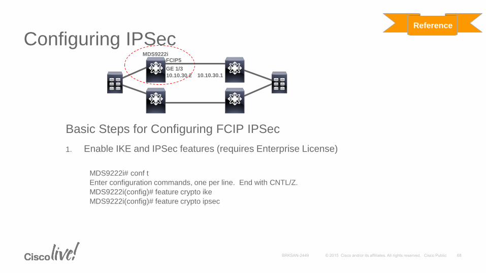
Configuring IPSec
Basic Steps for Configuring FCIP IPSec
1. Enable IKE and IPSec features (requires Enterprise License)
MDS9222i# conf t
Enter configuration commands, one per line. End with CNTL/Z.
MDS9222i(config)# feature crypto ike
MDS9222i(config)# feature crypto ipsec
Reference
FCIP5
GE 1/3
MDS9222i
10.10.30.2 10.10.30.1

Configuring IPSec
Basic Steps for Configuring FCIP IPSec
2. Configure IKE and ACLs
MDS9222i(config)# crypto ike domain ipsec
MDS9222i(config-ike-ipsec)# key LAB address 10.10.30.1
MDS9222i(config-ike-ipsec)# policy 1
MDS9222i(config-ike-ipsec-policy)# encryption 3des
MDS9222i(config-ike-ipsec-policy)# hash md5
MDS9222i(config-ike-ipsec-policy)# end
MDS9222i# conf t
Enter configuration commands, one per line. End with CNTL/Z.
MDS9222i(config)# ip access-list FCIP5 permit ip 10.10.30.2 0.0.0.0 10.10.30.1 0.0.0.0
MDS9222i(config)#
Reference

Configuring IPSec
Basic Steps for Configuring FCIP IPSec
3. Configure Transform Set and Crypto Map
MDS9222i(config)# crypto transform-set domain ipsec TFSET5 esp-aes 256 esp-sha1-hmac
MDS9222i(config)#
MDS9222i(config)# crypto map domain ipsec CMAP5 1
MDS9222i(config-crypto-map-ip)# match address FCIP5
MDS9222i(config-crypto-map-ip)# set peer 10.10.30.1
MDS9222i(config-crypto-map-ip)# set transform-set TFSET5
MDS9222i(config-crypto-map-ip)# set security-association lifetime seconds 3600
MDS9222i(config-crypto-map-ip)# set security-association lifetime gigabytes 4095
MDS9222i(config-crypto-map-ip)# set pfs group5
MDS9222i(config-crypto-map-ip)# end
MDS9222i#
Reference

Configuring IPSec
Basic Steps for Configuring FCIP IPSec
4. Bind the Crypto Map to the GE interface used by FCIP tunnelMDS9222i# conf t
Enter configuration commands, one per line. End with CNTL/Z.
MDS9222i(config)# interface gigabitethernet 1/3
MDS9222i(config-if)# crypto map domain ipsec CMAP5
MDS9222i(config-if)# no shut
5. Enable the FCIP tunnelMDS9222i(config)# interface fcip 5
MDS9222i(config-if)# no shut
MDS9222i(config-if)#
Full FCIP IPSec configuration example at:
http://www.cisco.com/c/en/us/td/docs/switches/datacenter/mds9000/sw/6_2/configuration/guides/security/nx-os/sec_cli_6-x/ipe.pdf
Reference

Application Acceleration
• Distance between data centers impacts performance of disk replication and tape backups
• Latency introduced by distance is compounded by multiple round trips per command
• Different acceleration methods are available to accelerate data over distance
I/O Accelerator (IOA) for disk and tape over FC or FCIP
Write Acceleration for disk over FCIP (FCIP-WA)
Tape Acceleration for tape over FCIP (FCIP-TA)

Acceleration Data Flow Concepts
• Synchronous Replication and Tape Backup are Similar – both have one outstanding I/O
• Tape drives further impacted by limited buffering and physical media
• Write Acceleration spoofs Transfer Ready only, Tape Acceleration spoofs Command Status
WRITE-1
XFER_RDYXFER_RDY
STATUS
DATA
Tape Acceleration (TA)
STATUS
WRITE-2
XFER_RDY
DATA
STATUS
XFER_RDY
STATUS
WRITE-1
WRITE-2
WRT file mark
WRT file mark
WRT fm stsWRT fm sts
TA TAWRITE
XFER_RDYXFER_RDY
Write Acceleration (WA)
Reduction in I/O
Latency ~equal to one
round trip time (RTT)
STATUS
DATA
WA WA

Replication IO Acceleration Use Cases
• Acceleration only works for replication or back-up protocols that use a SCSI write or SCSI-like write sequence with two round-trips
• EMC SRDF/s, SRDF/A, SRDF/AC, Mirrorview and SANcopy
• HDS TrueCopy
• HP CA-XP, CA-MVA
• IBM FlashCopy, FastT, XIV
• Protocols that use a single round trip do not require IO Acceleration
• EMC SRDF/S with SiRT enabled
• HDS Universal Replicator (HUR)
• HP CA-EVA
• IBM PPRC, PPRC-XD, XRC/Global Mirror, Metro Mirror

Port vs. Network Based Acceleration
• Port Based FCIP-WA and FCIP-TA only accelerate IOs egressing through their bound 1/10GE port
• Restrictions on HA topologies
• Only works with FCIP
• Accelerates all flows over a given FCIP interface
• Network Based IO Acceleration (IOA) accelerates any IO in the fabric over any ISL type
• No restrictions on HA topologies
• Can selectively accelerate flows based on PWWN on devices
• Both methods function the same at the SCSI layer

Comparison of Acceleration Methods
IOA-WA and IOA-TA FCIP-WA FCIP-TA
Attached Devices 1/2/4/8/16G 1/2/4/8/16G 1/2/4/8/16G
ISLs supported FC and FCIP FCIP FCIP
ISL Speed 1/2/4/8/10G 1/10GE 1/10GE
Port Channels Yes, up to 16 ISLs Yes, up to 16 ISLs No
Equal Cost Multi-Path Yes, up to 16 No No
Disk Acceleration Yes Yes No
Tape Acceleration Yes No Yes

FCIP-WA Design Considerations
FCIP-WA
requires
portchannels
to be
configured
High Availability and Load Balancing:
• Used for FCIP-WA for Disk replication (IPS, MPS and MSM, MDS 9222i and MDS 9250i)
• If FCIP Write Acceleration HA is required, then Portchannels must be used
• Equal cost FSPF load balancing for FCIP Write Acceleration not supported
• Works with:
• EMC SRDF, Mirrorview, SANCOPY
• HDS TrueCopy
• HP CA-XP, CA-MVA
• IBM FlashCopy, FastT

Configuring FCIP Write Acceleration
Configure FCIP Write Acceleration
mds9513-labD# conf t
Enter configuration commands, one per line. End with CNTL/Z.
mds9513-labD(config)# interface fcip 1
mds9513-labD(config-if)# write-accelerator
Enable FCIP write acceleration –
same for both sides of FCIP
tunnel
mds9513-labD# show interface fcip 1
fcip100
TCP Connection Information
.
.
Write acceleration mode is configured on; operationally on
Reference
FCIP1
GE 5/1
FCIP TA Design Requirements
• Tape Acceleration is not supported over Port-channels or equal cost FSPFpaths
Requirement due to state information kept in interface
• HA design requires costing parallel links so one path preferred over another
HA through redundant links
• Can use separate VSAN and FCIP tunnel to allow Port-channels for Write Acceleration

Configuring FCIP Tape Acceleration
Configure FCIP Write Acceleration
mds9513-labD# conf t
Enter configuration commands, one per line. End with CNTL/Z.
mds9513-labD(config)# interface fcip 1
mds9513-labD(config-if)# write-accelerator tape-accelerator
Enable FCIP tape acceleration –
same for both sides of FCIP
tunnel
mds9513-labD# sh int fcip 1
fcip1 is up
.
.
Write acceleration mode is configured on; operationally on
Tape acceleration mode is configured on; operationally on
Tape read acceleration mode is operationally on
Tape Accelerator flow control buffer size is automatic
Reference
FCIP1
GE 5/1
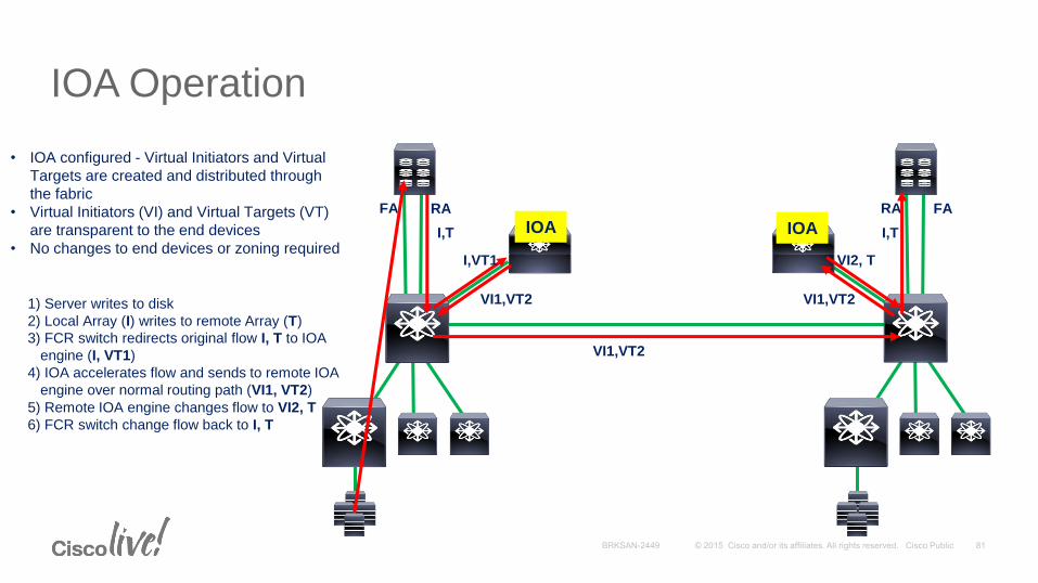
FA RA
1) Server writes to disk
2) Local Array (I) writes to remote Array (T)
3) FCR switch redirects original flow I, T to IOA
engine (I, VT1)
RA FA
IOA
4) IOA accelerates flow and sends to remote IOA
engine over normal routing path (VI1, VT2)
5) Remote IOA engine changes flow to VI2, T
6) FCR switch change flow back to I, T
• IOA configured - Virtual Initiators and Virtual
Targets are created and distributed through
the fabric
• Virtual Initiators (VI) and Virtual Targets (VT)
are transparent to the end devices
• No changes to end devices or zoning required
IOAI,T
I,VT1
VI1,VT2
VI1,VT2
VI1,VT2
VI2, T
I,T
IOA Operation

Site: rtp-bldg8Site: sjc-bldg6
FA RA RA FA
IOA Sites and Engines• IOA Site
A local set of switches within the fabric (e.g. sjc-bldg6)
• IOA Engine (interface)
Represents a Storage Service Engine within the MDS 9250i, MDS 9222i, SSN-16 or MSM-18/4
Ex. ioa2/1, ioa3/1-3/4
Note: a separate IOA license is required for each engine
IOA IOA

Site: rtp-bldg8Site: sjc-bldg6
FA RA RA FA
IOA Clusters• IOA Cluster
A set of IOA engines in a pair of IOA sites that operate as one group to provide IOA service
E.g. switches S1, S2, S3 and S4
Automatic load balancing among engine pairs
A site can be in multiple clusters (bunker sites)
A switch can be in multiple clusters
Note: an engine is bound to only one cluster
IOA IOA
IOA IOA
S1
S2
S3
S4
Cluster 1
Site: bunker
IOA
IOA

Site: rtp-bldg8Site: sjc-bldg6
FA RA RA FA
IOA Flows• IOA Flow
A flow accelerated within an IOA cluster
Each flow is identified by
{Initiator PWWN, Target PWWN, VSAN ID}
E.g. (DI1, DT1, V1) or (BI1, TT1, V1)
• IOA Flow Group
A set of IOA flows classified for a given purpose.
E.g. SRDF flow group and TSM flow group.
IOA IOADI1 DT1
BI2
TT1
BI1

IOA Deployment Considerations
• Limitations in FC-Redirect if Gen-1 modules are employed
Limit of 32 targets per switch -> Use Gen-2 or greater modules
• Zoning Considerations
Non-Optimal zoning (all servers to all disks) is not scalable
Cisco MDS 9000 Family I/O Accelerator Configuration Guide
http://www.cisco.com/c/en/us/td/docs/switches/datacenter/mds9000/sw/6_2/configuration/guides/ioa/ioa.pdf

Number of switches in a cluster 4
Number of Switches in the SAN for FC-Redirect 34
Number of IOA interfaces in a switch / cluster 44
Number of hosts per target 128
Number of flows in a cluster 1248
Number of flows across all clusters 1248
Number of flows per IOA service engine (hard limit) 128
Number of flows per IOA service engine (suggested soft limit) 64
IOA Scalability ConsiderationsReference

SAN Extension Fabric Stability
• Connecting new SAN fabrics or extending a SAN fabric can create SAN design challenges
• Minimize the impact of change in fabric services across geographically distributed sites
• Limit fabric control traffic such as RSCNs and Build/Reconfigure Fabric (BF/RCF) to local VSANs
• Connecting SAN fabrics with the same domain IDs
• Inter-VSAN Routing (IVR) can be used to address these challenges
• IVR enables a layer 3 hierarchical design to SAN fabrics to isolate domains
• IVR only sends selective RSCNs to edge switches, preventing disruption of fabric services
• IVR with NAT allows two existing SAN fabrics with the same domain ID to be connected through a third transit VSAN

SAN Extension with IVR
• Any failure in transit VSAN_20 (network equipment, physical or logical failure) will not disrupt VSAN_10 or VSAN_30 fabric
• Works with any transport service (FC, SONET/SDH, DWDM/CWDM, FCIP)
VSAN_5 - Site 1 Host Fabric
VSAN_10 - Site 1 Replication Fabric
VSAN_20 - Inter-site SAN Transit Fabric
VSAN_30 - Site 2 Replication Fabric
But is it required? Host traffic is already protected via
separate VSAN/fabric and if MAN/WAN goes down,
replication traffic will still be impacted.In
ter-V
SA
N C
on
nec
tion
betw
een
Co
mp
lete
ly Is
ola
ted
Fab
rics
Local
VSAN_5
Transit
VSAN_20
(IVR)
Replication
VSAN_10
Replication
VSAN_30
SAN Extension with IVR
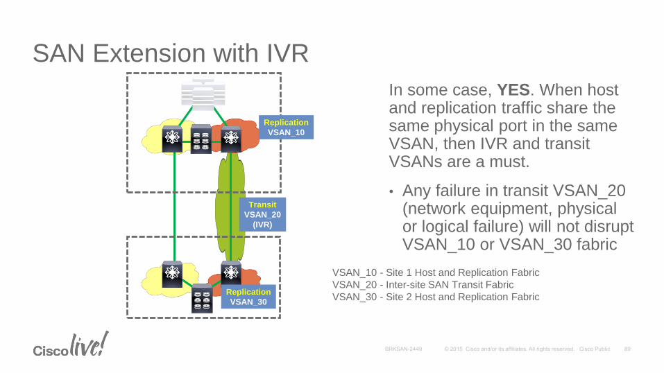
In some case, YES. When host and replication traffic share the same physical port in the same VSAN, then IVR and transit VSANs are a must.
• Any failure in transit VSAN_20 (network equipment, physical or logical failure) will not disrupt VSAN_10 or VSAN_30 fabric
VSAN_10 - Site 1 Host and Replication Fabric
VSAN_20 - Inter-site SAN Transit Fabric
VSAN_30 - Site 2 Host and Replication Fabric
Transit
VSAN_20
(IVR)
Replication
VSAN_10
Replication
VSAN_30

QoS for FCIP SAN Extension
Most FCIP Implementations use Dedicated Links, however:
• More FCIP deployments in converged IP network
• No generally accepted DSCP values for FCIP traffic
• QoS - Define Marking and classification
• Mark DSCP according to agreed value
• Separate consideration of FCIP data and control packet
• Bandwidth Reservation
• FCIP has no support for reservation protocol
• Achieved using Min / Max B/W command

FCIP QoS Mapping
• Synchronous Data Replication: Bursty, high bandwidth
• Mapped into Mission Critical (AF31 / DSCP 26)
• Asynchronous Data: Bursty, low to medium b/w
• Mapped into Transactional data (AF21 / DSCP 18)
• Or, mapped into Bulk data (AF11 / DSCP 10)
• Backup Data: 150 ~ 500 ms, constant (during backup), medium b/w
• Mapped into Bulk data (AF11 / DSCP 10)
• Control Packets
• Both Control and Data traffic can be assigned the same class
• If needed, Control Packets can be assigned CS6 or DSCP 48

Classification and Marking Design
ApplicationL3 Classification
DSCPPHBIPP CoS
FCIP ASYNC 18AF212 2
Call Signaling 24CS3*3 3
Streaming Video 32CS44 4
Video Conferencing 34AF414 4
Voice 46EF5 5
Network Management 16CS22 2
L2
FCIP backup / FCIP Async 10AF111 1
Scavenger 8CS11 1
Best Effort 000 0
Routing / FCIP control 48CS66 6
FCIP SYNC 26AF31*3 3
Value used when
configuring MDSModified for SAN Traffic

Configuring FCIP QOS
Configure FCIP QOS for Synchronous Replication
mds9513-labD# conf t
Enter configuration commands, one per line. End with CNTL/Z.
mds9513-labD(config)# interface fcip 1
mds9513-labD(config-if)# qos control 48 data 26
Enable FCIP QOS values on
both sides
mds9513-labD# MDS9222i# sh int fcip 1
fcip1 is up
.
.
.
QOS control code point is 48
QOS data code point is 26
TCP Connection Information
2 Active TCP connections
Reference
FCIP1
GE 5/1

FCIP Tuning

MDS FCIP Configuration Guidelines
• TCP Parameter settings
• Understanding FC Buffers and FCIP
• Monitoring for FC Frame expiry and why it is important
• Understanding MDS packet shaping methods so not to over run network
• Understanding MTU and the WAN network

• Use the proper bandwidth settings:tcp max-bandwidth and tcp min bandwidth
• Use the proper initial RTT setting:round-trip-time-us or round-trip-time-ms
• Measure using:ips measure-rtt or ping command
MDS9216-TOP# ips measure-rtt 200.200.200.2 int gig 2/4
Round trip time is 82 micro seconds (0.08 milli seconds)
or
MDS9216-TOP# ping 200.200.200.1
--- 200.200.200.1 ping statistics ---
rtt min/avg/max/mdev = 0.068/0.079/0.091 ms
MDS FCIP – TCP Parameters
fcip profile 1
ip address 200.200.200.1
tcp max-bandwidth-mbps 800 min-available-bandwidth-mbps 500 round-trip-time-us 80

MDS FCIP – TCP Parameters• Always use Selective ACK (SACK) – on by default
• If slow link (<T3/E3):
Keep tcp cwm burstsize low (<20kB)
Tune FC receive buffers—BB_Credits and performance buffers (fcrxbbcredit)
• If shared link (other traffic):
Determine available bandwidth (link b/w – other traffic b/w) and set max-bandwidth = available bandwidth and min-available-bandwidth = 80-95% max-bandwidth
Consider QoS policies; carving out bandwidth
• If shared link (other FCIP tunnel):
Determine available bandwidth (link b/w – other traffic b/w) and set max-bandwidth = 50% available bandwidth and min-available-bandwidth = 80-95% max-bandwidth
• If a dedicated link:
Set min=95% max and max=path bandwidth (FCIP will send at this rate)
If GE/10GE all the way, set tcp cwm burstsize to 100kB

Frame Expiration
• 500ms timer is fixed (not configurable)
• Frame expiration possible whenever FC Rx buffers cannot drain at a sufficient rate (at least 2x #Rx buffers/second)
Caused by one or more of:• too many sources (speed mismatch)
• slow downstream (slow receiver)
• FC Rx buffers too deep
• Possible causes are:
Long optical links with low BB_Credits (i.e. can’t drain quickly)— misconfiguration
FCIP over long, slow links (e.g. T1 or T3 with 50+ms RTT) with occasional packet loss/retransmission

Monitor FCIP Frame TimeoutsMDS9216-TOP# show ips stats dma int gigabitethernet 2/4
Dma-bridge ASIC Statistics for port GigabitEthernet2/4
Hardware Egress Counters
1030008889 Good, 0 bad protocol, 0 bad header cksum, 0 bad FC CRC
Hardware Ingress Counters
1843269599 Good, 0 protocol error, 0 header checksum error
0 FC CRC error, 0 iSCSI CRC error, 0 parity error
Software Egress Counters
1030008581 good frames, 0 bad header cksum, 0 bad FIFO SOP
0 parity error, 0 FC CRC error, 0 timestamp expired error
0 unregistered port index, 0 unknown internal type
0 RDL ok, 0 RDL drop (too big), 0 RDL ttl_1
1278210315 idle poll count, 116279 loopback
0 FCC PQ, 0 FCC EQ, 0 FCC generated
Flow Control: 0 [0], 0 [1], 0 [2], 0 [3]
Software Ingress Counters
1843269472 Good frames, 0 header cksum error, 0 FC CRC error
0 iSCSI CRC error, 0 descriptor SOP error, 0 parity error
141281 frames soft queued, 0 current Q, 732 max Q, 0 low memory
0 out of memory drop, 0 queue full drop
0 RDL ok, 0 RDL drop (too big)
Flow Control: 0 [0], 141281 [1], 0 [2], 0 [3]
Monitor for 500msTimeout Issues

TCP Window and Buffer with FCIP
MDS9216-TOP# sh interface fcip 2 counters
--snip--
TCP Parameters
Path MTU 1500 bytes
Current retransmission timeout is 200 ms
Round trip time: Smoothed 2 ms, Variance: 4
Advertized window: Current: 97 KB, Maximum: 97 KB, Scale: 5
Peer receive window: Current: 98 KB, Maximum: 98 KB, Scale: 5
Congestion window: Current: 52 KB, Slow start threshold: 103 KB
Current Send Buffer Size: 97 KB, Requested Send Buffer Size: 0 KB
CWM Burst Size: 50 KB
--snip--
IP compression statistics
4059579130004 rxbytes, 273626035160 rxbytes compressed
2287961989360 txbytes 633365852164 txbytes compressed, 0 txbytes non-compressed
3.61 tx compression ratio
You cannot configure the TCP window size directly. This value is automatically calculated from the product of the maximum bandwidth x RTT.
In SAN-OS 2.0 and later, the RTT will dynamically adjust up to eight times the configured value in the FCIP profile. The TCP sender dynamically changes the maximum window size accordingly.
TCP send buffer can be increased to allow faster removal of frame off FC interface RX buffer

FCIP Capacity Planning

FCIP – Capacity Planning
• Creates a virtual N-port on an IPS, MPS, MSM, SSN-16 or 9250i port that can act as both initiator and target to generate traffic
• Measures throughput and response time per I/O over FCIP tunnels
• Model effect of storage data in a shared network
SAN Extension Tuner (SET) is a lightweight tool to assist in FCIP tuning by generating various SCSI traffic flows
IP Network
FCIP Tunnel
Gig3/1
Gig3/3
Gig2/1
Gig2/2
N-port: 10:00:00:00:00:00:00:01 N-port: 11:00:00:00:00:00:00:03

Using SAN Extension Tuner
• SAN Extension-Tuner uses unused iSCSI interfaces as a FC Initiator and Target
• FC traffic is sent across FCIP ISL link for WAN load test, help tune TCP parameters and exercise features
• To achieve desired throughput across FCIP a number of parameters must be tuned to keep WAN pipe full:
TCP Parameters (Window size, SACK…)
Outstanding SCSI I/Os allowed by application
Transfer size used by application
• Requires 2.0 SAN-OS or greater
Note: MSM 18+4/9222i require SAN-OS 3.3(1) or higher

SAN Extension Tuner
• Only read and write SCSI commands are used, entire SCSI suite is not supported
• Multiply Virtual N-ports can be created to:
Overload FCIP link to stress WAN Provisioning
Test Compression Results
Troubleshoot issues without using real FC devices
• Use data provided with tool or use your own
• Simple Setup Wizard
Wizard automatically creates Zone for the virtual N-ports

SET Use from Fabric Manager
Click on FCIP Link

Auto Created Zone
SET – Monitor Results, Make AdjustmentsMonitor ISL Link Utilization Tool

Q&A

Other Storage Networking Related Sessions
• BRKSAN-2101 -- FCoE for Small and Mid Size Enterprises
• Monday 8:00 - 31C Upper Level
• BRKSAN-3101 Troubleshooting Cisco MDS 9000 Fibre Channel Fabrics
• Monday 13:00 - 28B Upper Level
• BRKSAN-3446 SAN Congestion! Understanding, Troubleshooting, Mitigating in a Cisco Fabric
• Wednesday 13:00 - 28C Upper Level
• BRKSAN-2282 Operational Models for FCoE Deployments - Best Practices and Examples
• Wednesday 15:30 - 10 Upper Level
• BRKSAN-2883 Advanced Storage Area Network Design
• Thursday 13:00 - 25AB Upper Level

Additional Information
• Cisco Storage Networking
• http://www.cisco.com/go/storagenetworking
• Cisco Data Center Networking
• http://www.cisco.com/go/datacenter
• Storage Network Industry Association (SNIA)
• http://www.snia.org
• Internet Engineering Task Force—IP Storage
• http://www.ietf.org/html.charters/ips-charter.html
• ANSI T11—Fibre Channel
• http://www.t11.org/index.html

Participate in the “My Favorite Speaker” Contest
• Promote your favorite speaker through Twitter and you could win $200 of Cisco Press products (@CiscoPress)
• Send a tweet and include
• Your favorite speaker’s Twitter handle
• Two hashtags: #CLUS #MyFavoriteSpeaker
• You can submit an entry for more than one of your “favorite” speakers
• Don’t forget to follow @CiscoLive and @CiscoPress
• View the official rules at http://bit.ly/CLUSwin
Promote Your Favorite Speaker and You Could Be a Winner

Complete Your Online Session Evaluation
Don’t forget: Cisco Live sessions will be available for viewing on-demand after the event at CiscoLive.com/Online
• Give us your feedback to be entered into a Daily Survey Drawing. A daily winner will receive a $750 Amazon gift card.
• Complete your session surveys though the Cisco Live mobile app or your computer on Cisco Live Connect.

Continue Your Education
• Demos in the Cisco Campus
• Walk-in Self-Paced Labs
• Table Topics
• Meet the Engineer 1:1 meetings

Data Center / Virtualization Cisco Education OfferingsCourse Description Cisco Certification
Cisco Data Center CCIE Unified Fabric
Workshop (DCXUF);
Cisco Data Center CCIE Unified Computing
Workshop (DCXUC)
Prepare for your CCIE Data Center practical exam with hands on lab
exercises running on a dedicated comprehensive topology
CCIE® Data Center
Implementing Cisco Data Center Unified Fabric
(DCUFI);
Implementing Cisco Data Center Unified
Computing (DCUCI)
Obtain the skills to deploy complex virtualized Data Center Fabric and
Computing environments with Nexus and Cisco UCS.
CCNP® Data Center
Introducing Cisco Data Center Networking
(DCICN); Introducing Cisco Data Center
Technologies (DCICT)
Learn basic data center technologies and how to build a data center
infrastructure.
CCNA® Data Center
Product Training Portfolio: DCAC9k, DCINX9k,
DCMDS, DCUCS, DCNX1K, DCNX5K, DCNX7K
Get a deep understanding of the Cisco data center product line including
the Cisco Nexus9K in ACI and NexusOS modes
For more details, please visit: http://learningnetwork.cisco.com
Questions? Visit the Learning@Cisco Booth or contact [email protected]

Thank you

FCIP Troubleshooting
FCIP CLI Commands
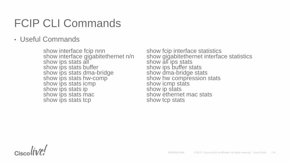
• Useful Commands
show interface fcip nnn show fcip interface statisticsshow interface gigabitethernet n/n show gigabitethernet interface statisticsshow ips stats all show all ips statsshow ips stats buffer show ips buffer statsshow ips stats dma-bridge show dma-bridge statsshow ips stats hw-comp show hw compression statsshow ips stats icmp show icmp statsshow ips stats ip show ip statsshow ips stats mac show ethernet mac statsshow ips stats tcp show tcp stats
Command Line Debugging
• Available debugs depend on features enabled in SAN-OS and NX-OS
• Many different options to select when turning on debugs
• Interface and protocol level debugging available
• Where is it output going?
• Logfile—data file in switch memory
• Capture to direct to screen via console, telnet or ssh
• Requires admin privileges to run debugs
• Debugs can only be run from cli, no debug interface in Fabric Manager or Device Manager
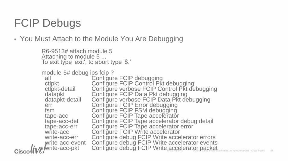
FCIP Debugs
• You Must Attach to the Module You Are Debugging
R6-9513# attach module 5Attaching to module 5 ...To exit type 'exit', to abort type '$.‘
module-5# debug ips fcip ?all Configure FCIP debuggingctlpkt Configure FCIP Control Pkt debuggingctlpkt-detail Configure verbose FCIP Control Pkt debuggingdatapkt Configure FCIP Data Pkt debuggingdatapkt-detail Configure verbose FCIP Data Pkt debuggingerr Configure FCIP Error debuggingfsm Configure FCIP FSM debuggingtape-acc Configure FCIP Tape acceleratortape-acc-det Configure FCIP Tape accelerator debug detailtape-acc-err Configure FCIP Tape accelerator errorwrite-acc Configure FCIP Write acceleratorwrite-acc-err Configure debug FCIP Write accelerator errorswrite-acc-event Configure debug FCIP Write accelerator eventswrite-acc-pkt Configure debug FCIP Write accelerator packet

Gathering Protocol Traces for Analysis
• Using built-in FC Analyzer (CLI)
• Using Cisco Protocol and Traffic Analyzer on PC (local & remote)
• Using SPAN
• Using an external FC Analyzer
All non-disruptive to switch operations and traffic on the SAN

MDS FCAnalyzer SAN-OS and NX-OS Imbedded
• Output is displayed to the console in readable sniffer like format
• Is only used to monitor Fibre Channel Traffic to and from supervisor on the MDS9000
• Traffic like Fabric Login’s, FSPF routing, Switch to switch control traffic
• Output can go direct to your console screen or to a workstation running Ethereal program
Note: SPAN is used not only for FC port to FC port monitoring, but also used to SPAN iSCSI and FCIP ports

FCanalyzer Options
• Local or remote - where to send the trace; can be to local devices or remote analyzer attached to different MDS switch
• Brief or detailed - header information vs. full output of frame including hex; detail is default
• Limit-captured-frames - number of frames to capture; default is fcanalyzer will trace 100 frames; specifying zero is unlimited frame capture
• Limit-capture-size - allows to capture N number of bytes of frame; useful for not capturing frame data when it is not relevant to troubleshooting

MDS9216-TOP# conf tEnter configuration commands, one per line. End with CNTL/Z.
MDS9216-TOP(config)# fcanalyzer local brief display-filter mdshdr.vsan==300
Warning: Couldn't obtain netmask info (eth2: no IPv4 address assigned).Capturing on eth2
8.986146 ff.ff.fd -> ff.ff.fd 0x46a6 0xffff SW_ILS ELP8.986233 ff.ff.fd -> ff.ff.fd 0x46a6 0x469a FC Link Ctl, ACK18.987140 ff.ff.fd -> ff.ff.fd 0x469b 0xffff SW_ILS ELP8.987539 ff.ff.fd -> ff.ff.fd 0x469b 0x46a7 FC Link Ctl, ACK18.988273 ff.ff.fd -> ff.ff.fd 0x469b 0x46a7 SW_ILS SW_RJT (ELP)8.988790 ff.ff.fd -> ff.ff.fd 0x46a6 0x469a SW_ILS SW_ACC (ELP)8.989438 ff.ff.fd -> ff.ff.fd 0x469b 0x46a7 FC Link Ctl, ACK18.991501 ff.ff.fd -> ff.ff.fd 0x46a6 0x469a FC Link Ctl, ACK18.992965 ff.ff.fd -> ff.ff.fd 0x46a8 0xffff SW_ILS EFP8.993037 ff.ff.fd -> ff.ff.fd 0x46a8 0x469c FC Link Ctl, ACK19.001146 ff.ff.fd -> ff.ff.fd 0x469d 0xffff SW_ILS EFP9.001603 ff.ff.fd -> ff.ff.fd 0x469d 0x46a9 FC Link Ctl, ACK19.001719 ff.ff.fd -> ff.ff.fd 0x46a8 0x469c SW_ILS SW_ACC (EFP)
Using the FCanalyzer with FCIP
• Filter on VSAN 300
• No shut of FCIP interface
• Complete view of standard ISL initialization and switch fabric merge
• You do not capture FCIP protocol; FCIP protocol is viewed with debugs and/or SPAN (monitor) of WAN network

Use of SPAN Feature
• Used for FC port to FC port analyzing
• Same type of tool as used on Cisco Catalyst® products (Catalyst uses Port Monitor)
• Can be left configured on switch
• Ingress and egress ports are sent to an FC-port setup as a SPAN Destination (SD-port type)
• No limits to where the ports are located on the MDS switch fabric
• Used to output to third-party test equipment

Display filters can be applied before or after capture
Right click on field to filter
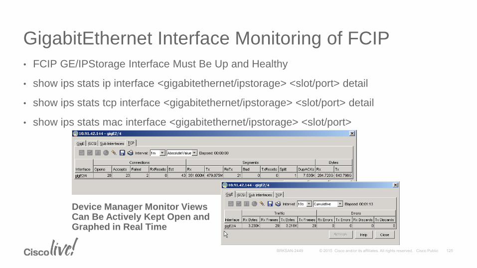
GigabitEthernet Interface Monitoring of FCIP
• FCIP GE/IPStorage Interface Must Be Up and Healthy
• show ips stats ip interface <gigabitethernet/ipstorage> <slot/port> detail
• show ips stats tcp interface <gigabitethernet/ipstorage> <slot/port> detail
• show ips stats mac interface <gigabitethernet/ipstorage> <slot/port>
Device Manager Monitor Views Can Be Actively Kept Open and Graphed in Real Time
