stock & quick build catalog - greenheck fan · stock & quick build catalog volume 23 this...
TRANSCRIPT

Greenheck Quick DeliveryStock & Quick Build CatalogVolume 23
This catalog is being sent to you on behalf of:
Greenheck Quick DeliveryStock & Quick Build CatalogVolume 23
3,000 Ventilation Products Available In-stock or on Quick Build Program
What’s NEW?
Make-Up Air & Lab Exhaust
Models

Roof Mounted Fans Page(s)Model G 4-5
Model GB 6-9
Models LD/LDP 10
Models LB/LBP 11
Models CUE/CUE-HP 12-13
Model CUBE 14-17
Model USGF 18
Models CW/CW-HP/CWB/CWB-HP 19-21
Models RDU/RBU/RBUMO 22-23
Models RGU 24
Models TAUD/TAUB/TAUB-CA 25-26
Model SAF 27-28
Models RSF/RSFP 29-30
Models R/RB 31-32
Models RPDR/RPBR 33-34
Models AE/AS 35
Gravity VentilatorsModel GRS/GRSF 36
Models FGI/FGR 37
Roof CurbsRoof Curbs & Extensions 38-39
Ceiling and Cabinet FansModel SP 40-41
Model CSP 42-43
SP/CSP Accessories 44-47
Inline FansModel BCF 48
Model BDF 49
Model SQ/BSQ 50-53
Inline Fans Accessories 54-55
Model TCB 56
Model TCF 57
Model QEI 58-59
Models TDI/TBI-FS/TBI-CA 60-61
Model VAB 62
Sidewall Exhaust FansModels S/SB 63-68
Model CBF 69
Model DF 69
Utility FansModels SFD/SFB 70-71
Model SWB 72-75
Centrifugal FansModels BISW/AFSW/BIDW/AFDW 77
Radial BlowersModels IPO/IPW/IPA 78
Plenum FanModel QEP 79
Vektor Laboratory Exhaust SystemsVektor-H 80-81
RO
OF
CU
RB
S
LA
B E
XH
AU
ST
SY
STE
MS
RO
OF M
OU
NTE
D F
AN
S &
GR
AV
ITY
VE
NTIL
ATO
RS
INLIN
E, C
EIL
ING
& S
IDE
WA
LL
EX
HA
US
T F
AN
S
UTIL
ITY,
CE
NTR
IFU
GA
L &
R
AD
IAL B
LO
WE
RS

Kitchen Ventilation Page(s)Type I Kitchen Hoods 82
Type II Kitchen Hoods 83
Energy Recovery VentilatorsModel ERV 84-85
Model Minivent-450/750 85
Make-Up Air SystemsModels DGK/DG/DGx 86-87
Models IG/IGx 88-89
Models KSFD/KSFB 90-91
Indoor Air Handlers and Fan CoilsModel VFCB/VFCD 92-93
Model HFCB/HFCD 94-95
Model LFC 96 & 98
Model MSCF 97-98
Underfl oor Fan DistributionModel UFT 99
CoilsCustom Coils 100
DampersCurtain and Multi-Blade Fire Dampers 101
Smoke Dampers 102
Fire Smoke Dampers 103-104
Access Doors 105
Marine Dampers 105
Ceiling Radiation Dampers 106
Volume Control Dampers 107
Insulated Control Dampers 108
Manual Balancing Dampers 108
Industrial Dampers 109
Barometric Relief Dampers 109
Backdraft Dampers 110
LouversDrainable Blade & Drainable Head 111
Nondrainable, Recessed Mullion & Thinline 112
Adjustable Blade & Combination Louvers/Dampers
113
Sightproof & Acoustical 114
Fabricated & Wind-Driven Rain 115
Florida Product Approved/Miami-Dade 116
Louvered Penthouses 117
Brick Vents 117
Options and AccessoriesMounting Options 118
Coatings 119
Electrical Accessories 120
Replacement Parts 120
Fan Fundamentals and Representatives DirectoryFan Fundamentals 121-125
Greenheck Representatives Directory 126-134
FA
N
FU
ND
AM
EN
TA
LS
&
RE
P D
IRE
CTO
RY
OP
TIO
NS
D
AM
PE
RS
LO
UV
ER
SE
NE
RG
Y R
EC
OV
ER
Y, M
AK
E-U
P A
IR,
IND
OO
R A
IR H
AN
DLE
RS
, FA
N C
OIL
S,
UN
DE
RFLO
OR
FA
NS
, CO
ILS
KIT
CH
EN
V
EN
TIL
ATIO
N
SPARTANWHITE
IVORyMARBLE
DESERT SAND
HAMPTONBROWN
TAUPE
MEDIUM BRONZE
CLASSICBRONZE

R O O F M O U N T E D F A N S4
MODEL A B C* ROOFOPENING
DAMPER SIZE
IN STOCK SIZES (n)
MIN/MAX RPM
SONES @ 0 IN.
PERFORMANCE IN INCHES WG0 .125 .25 .5 .75 1
G-060 17 193⁄8 121⁄8 101⁄2 x 101⁄2
8 x 8
n1050 1.7 138 731550 4.2 203 166 120
G-065 17 193⁄8 121⁄8 101⁄2 x 101⁄2 n1050 2.2 187 1101550 4.9 276 232 176
G-070 17 193⁄8 121⁄8 101⁄2 x 101⁄2 n1050 2.7 254 1791550 5.6 374 327 274
G-075 17 193⁄8 121⁄8 101⁄2 x 101⁄2 n1050 3.6 296 2001550 6.1 438 377 310
G-080 17 213⁄4 145⁄8 121⁄2 x 121⁄2
10 x 10
n1050 3.8 335 249 1341550 7.3 495 439 379 238
G-085 17 213⁄4 145⁄8 121⁄2 x 121⁄2 n1050 4.0 399 307 1791550 7.6 588 529 464 308
G-090 17 213⁄4 145⁄8 121⁄2 x 121⁄2 n1050 4.0 520 420 2921550 7.6 768 700 633 472
G-095 17 213⁄4 145⁄8 121⁄2 x 121⁄2 n1050 5.4 717 569 3891550 9.6 1059 969 863 623
G-101 19 245⁄8 20 141⁄2 x 141⁄212 x 12
n860 4.3 766 588 2391725 12.1 1536 1454 1374 1181 974
G-121 19 245⁄8 20 141⁄2 x 141⁄2 n860 5.6 922 723 4491725 14.1 1849 1753 1659 1453 1223
G-131 22 287⁄8 20 181⁄2 x 181⁄2
16 x 16
n860 6.5 1193 1011 7711725 19.2 2393 2310 2222 2030 1820 1555
G-141 22 287⁄8 20 181⁄2 x 181⁄2 n860 6.8 1376 1160 9191140 10.4 1824 1667 1498 1112
G-150 26 351⁄2 211⁄8 181⁄2 x 181⁄2 n860 7.9 1772 1552 13051140 11.7 2348 2184 2016 1629 1115
G-160 30 351⁄2 215⁄8 201⁄2 x 201⁄2
18 x 18
n860 8.0 2008 1783 1535 5521140 13.6 2662 2489 2319 1932 1411
G-170 30 351⁄2 215⁄8 201⁄2 x 201⁄2860 9.7 2572 2329 2077 14171140 16.3 3409 3226 3042 2647 2182 1458
G-180 30 351⁄2 223⁄4 201⁄2 x 201⁄2860 12.1 3240 3002 2733 19781140 19.5 4295 4122 3933 3509 2971 2247
Roof Mounted Fans and Gravity Ventilators Roof Exhaust Direct Drive - GModel G centrifugal roof exhaust fans are direct drive. These fans are specifically designed for roof mounted applications exhausting relatively clean air. Fan wheels are centrifugal, backward-inclined, and constructed of aluminum.
PERFORMANCEPerformance capabilities range from 73 cfm to 4,295 cfm and up to 1 in. wg of static pressure.
For complete product information refer to catalog Model G and GB, or contact your local representative.
Greenheck Fan Corporation certifies that the Model G fans shown herein are licensed to bear the AMCA Seal. The ratings shown are based on tests and procedures performed in accordance with AMCA Publication 211 and Publication 311 and comply with the requirements of the AMCA Certified Ratings Program.
n Performance for available in stock sizes is shown on page 5
*May be greater depending on motor. All dimensions in inches.Dimension A - given is the inside dimensions of the curb cap. The roof curb should be 11/2 in. less than the curb cap to allow for roofing and flashing. Performance certified is for installation type A: Free inlet, Free outlet. Power rating (BHP) does not include transmission losses. Performance ratings include the effects of a birdscreen. The sound ratings shown are loudness values in fan sones at 5 ft. (1.5 m) in a hemispherical free field calculated per AMCA Standard 301. Values shown are for installation type A: Free inlet hemispherical sone levels. The AMCA Certified Ratings Seal applies to sone ratings only.
A
B
C
13/4 in.
*

R O O F M O U N T E D F A N S 5
Roof Exhaust Direct Drive - G
G PERFORMANCE DATA - IN STOCK MODEL RPM TS SONES @
0 IN.MAXBHP
PRESSURE IN INCHES WG0 .125 .25 .375 .5 .625 .75
G-060-DGEX-QD1/60 HP3 Speed
E 1050 2234 1.7 .005 138 73G 1300 2765 2.9 .009 170 125D 1550 3297 4.2 .016 203 166 120
G-065-DGEX-QD1/30 HP3 Speed
E 1050 2234 2.2 .007 187 110G 1300 2765 3.2 .012 231 178 91D 1550 3297 4.9 .022 276 232 176 96
G-070-DGEX-QD1/30 HP3 Speed
E 1050 2234 2.7 .008 254 179G 1300 2765 4.1 .015 314 257 171D 1550 3297 5.6 .026 374 327 274 190
G-075-DGEX-QD1/25 HP3 Speed
E 1050 2234 3.6 .011 296 200G 1300 2765 4.1 .021 367 294 195D 1550 3297 6.1 .035 438 377 310 214
G-080-DGEX-QD1/20 HP3 Speed
E 1050 2990 3.8 .017 335 249 134G 1300 3701 5.4 .033 415 348 272 175D 1550 4413 7.3 .057 495 439 379 314 238
G-085-DGEX-QD1/20 HP3 Speed
E 1050 2990 4.0 .019 399 307 179G 1300 3701 5.5 .036 494 421 340 233D 1550 4413 7.6 .062 588 529 464 393 308 169
G-090-DGEX-QD1/15 HP3 Speed
E 1050 2990 4.0 .024 520 420 292G 1300 3701 5.4 .045 644 564 478 373D 1550 4413 7.6 .076 768 700 633 558 472 338
G-095-DGEX-QD1/8 HP
3 Speed
E 1050 2990 5.4 .037 717 569 389G 1300 3701 7.6 .071 888 780 640 493 184D 1550 4413 9.6 .120 1059 969 863 745 623 474
G-101-BX-QD1/6 HP 1140 3488 7.1 .06 1015 893 747 568
G-101-AX-QD1/4 HP 1725 5278 12.1 .22 1536 1454 1374 1277 1181 1086 974
G-121-BX-QD1/6 HP 1140 3712 8.1 .09 1222 1078 918 734 335
G-121-AX-QD1/4 HP 1725 5617 14.1 .30 1849 1753 1659 1560 1453 1341 1223
G-131-BX-QD1/6 HP 1140 4160 9.9 .13 1581 1452 1303 1129 889 381
G-141-BX-QD1/6 HP 1140 4365 10.4 .17 1824 1667 1498 1313 1112 794
G-150-BX-QD1/4 HP 1140 4775 11.7 .29 2348 2184 2016 1837 1629 1398 1115
G-160-BX-QD1/3 HP 1140 4887 13.6 .32 2662 2489 2319 2135 1932 1697 1411
SERVICE CHART IN STOCK
NEXT DAY
3 DAY
10 DAY
Sizes G-060 through 160 ✓ ✓ ✓ ✓
Sizes G-170 & G-180 ✓ ✓ ✓
in stock sizes include birdscreen, disconnect switch, UL/cUL 705 electrical.
OPTIONS AND ACCESSORIES • Gravityandmotorizeddampers(InStock)• Galvanizedroofcurbs(InStock)• Aluminumroofcurbs(Seepages38-39)• Extendedbases• Insectscreenbases• Aluminumbirdscreen• Curbseal• Hingedcurbcapw/cable• Curbadaptors• Tie-downpoints• Speedcontrols(InStock)• UL/cUL705Electrical• NEMA-3RandEXPdisconnectswitches• Highwind• Greenheckcoatings(Seecoatingspage119)
Performance certified is for installation type A: Free inlet, Free outlet. Power rating (BHP) does not include transmission losses. Performance ratings include the effects of a birdscreen. The sound ratings shown are loudness values in fan sones at 5 ft. (1.5 m) in a hemispherical free field calculated per AMCA Standard 301. Values shown are for installation type A: Free inlet hemispherical sone levels. The AMCA Certified Ratings Seal applies to sone ratings only.
STANDARD CONSTRUCTION FEATURES• Aluminumhousing • Non-overloadingbackward-inclinedwheel • Aluminumcurbcapwithprepunchedmountingholes• Integralreinforcedbeadforstrengthonhood • Galvanizedbirdscreen • Ballbearingmotors(sizes101-180),sleevebearingmotors (sizes 060-095) • Double-studdedisolatorsfortruevibrationisolation• Corrosion-resistantfasteners• NEMA-1disconnect

R O O F M O U N T E D F A N S6
A
B
C*
13/4 in.
For complete product information refer to catalog Model G and GB, or contact your local representative.
Greenheck Fan Corporation certifies that the Model GB fans shown herein are licensed to bear the AMCA Seal. The ratings shown are based on tests and procedures performed in accordance with AMCA Publication 211 and Publication 311 and comply with the requirements of the AMCA Certified Ratings Program.
*May be greater depending on motor. All dimensions in inches. Dimension A - given is the inside dimensions of the curb cap.The roof curb should be 11/2 in. less than the curb cap to allow for roofing and flashing. Performance certified is for installation type A: Free inlet, Free outlet. Power rating (BHP) does not include transmission losses. Performance ratings include the effects of a birdscreen. The sound ratings shown are loudness values in fan sones at 5 ft. (1.5 m) in a hemispherical free field calculated per AMCA Standard 301. Values shown are for installation type A: Free inlet hemispherical sone levels. The AMCA Certified Ratings Seal applies to sone ratings only.
GB CONDENSED PERFORMANCE RANGES & DIMENSIONAL DATA n Performance for available in stock sizes is shown on pages 8 & 9
UL/cUL 705E40001 - GB
MODEL A B C* ROOFOPENING
DAMPER SIZE
IN STOCK SIZES (n)
MIN/MAX RPM
SONES @ 0 IN.
PERFORMANCE IN INCHES WG0 .25 .5 .75 1 1.25 1.5 1.75 2.0
GB-071 19 243⁄8 233⁄4 141⁄2 x 141⁄2
12 x 12
n 600 1.2 131 68
1710 11.1 372 334 292 245 198
GB-081 19 243⁄8 233⁄4 141⁄2 x 141⁄2 n600 2.2 301 175
1710 12.5 856 784 710 629 480
GB-091 19 243⁄8 233⁄4 141⁄2 x 141⁄2 n600 2.7 455 271
1710 13.4 1295 1179 1061 934 785
GB-101 19 243⁄8 233⁄4 141⁄2 x 141⁄2 n700 3.7 593 455
1800 13.2 1525 1418 1320 1208 1064 793
GB-121 19 243⁄8 233⁄4 141⁄2 x 141⁄2 n595 3.3 721
1725 17.4 2093 1984 1871 1743 1600 1426
GB-131 19 283⁄8 233⁄4 141⁄2 x 141⁄2 n595 4.5 844 655
1685 16.9 2391 2278 2157 2020 1857 1654
GB-141 22 283⁄8 233⁄4 181⁄2 x 181⁄216 x 16
n525 4.4 974 709
1705 20 3163 3020 2883 2739 2574 2370
GB-161 22 283⁄8 233⁄4 181⁄2 x 181⁄2 n478 4.7 1412 1030
1375 21 4062 3815 3571 3304 3007 2609 2073
GB-180 30 351⁄2 28 201⁄2 x 201⁄218 x 18
n495 4.3 1924 1150
1460 26 5677 5514 5335 5155 4938 4698 4426 4123 3765
GB-200 30 351⁄2 28 201⁄2 x 201⁄2 n440 6.5 2434
1200 24 6640 6336 5968 5650 5274 4828 4177 3077
GB-220 34 423⁄4 311⁄2 261⁄2 x 261⁄224 x 24
330 6.6 2507985 23 7484 7212 6898 6568 6106 5547 4883
GB-240 34 423⁄4 311⁄2 261⁄2 x 261⁄2 n425 5.9 3902 3422 2691910 24 8355 7916 7467 6932 6240 5388 3707
GB-260 40 50 36 321⁄2 x 321⁄230 x 30
270 7.7 3487835 23 10784 10292 9794 9225 8606 7932 7157 6024 4294
GB-300 40 50 36 321⁄2 x 321⁄2 n300 9.3 4859 3976890 28 14416 13897 13335 12716 12072 11379 10536 9568 7963
GB-330 46 583⁄4 381⁄2 381⁄2 x 381⁄236 x 36
255 5.2 6159700 28 16908 16185 15408 14564 13624 12640 11538 10184
GB-360 46 583⁄4 381⁄2 381⁄2 x 381⁄2 215 4.8 5750685 30 18321 17560 16711 15773 14710 13534 12119
GB-420 52 651⁄4 44 441⁄2 x 441⁄2 42 x 42 180 2.5 7417600 30 24724 23765 22709 21620 20103 18584 16590
GB-480 58 733⁄4 471⁄4 501⁄2 x 501⁄2 48 x 48 150 5.6 9015485 31 29148 27622 26016 24290 22106 19516
GB-500 64 83 503⁄4 561⁄2 x 561⁄254 x 54
160 5.9 12893460 33 37068 34991 32805 30342 27917 25310
GB-540 64 83 503⁄4 561⁄2 x 561⁄2 160 6.3 14160505 40 44694 43221 41157 38813 36503 33869 31293 26758
Roof Exhaust Belt Drive - GBModel GB centrifugal roof exhaust fans are belt drive. These fans are specifically designed for roof mounted applications exhausting relatively clean air. Fan wheels are centrifugal, backward-inclined, and constructed of aluminum. Adjustable motor pulleys allow for final system balancing.
PERFORMANCEPerformance capabilities range from 140 cfm to 44,690 cfm and up to 2.0 in. wg of static pressure.

R O O F M O U N T E D F A N S 7
*May be greater depending on motor. All dimensions in inches.Dimension A - given is the inside dimensions of the curb cap.The roof curb should be 11/2 in. less than the curb cap to allow for roofing and flashing. Performance certified is for installation type A: Free inlet, Free outlet. Power rating (BHP) does not include transmission losses. Performance ratings include the effects of a birdscreen. The sound ratings shown are loudness values in fan sones at 5 ft. (1.5 m) in a hemispherical free field calculated per AMCA Standard 301. Values shown are for installation type A: Free inlet hemispherical sone levels. The AMCA Certified Ratings Seal applies to sone ratings only.
GB HIGH PRESSURE PERFORMANCE & DIMENSIONAL DATA in stock sizes not available for High Pressure
MODEL A B C* ROOF OPENING
DAMPER SIZE
MIN/MAX RPM
SONES @ 0.25 IN.
PERFORMANCE IN INCHES WG
.25 .5 .75 1 1.5 2 2.5 2.75 3 3.25
GB-101HP 19 243⁄8 233⁄4 141⁄2 x 141⁄2 12 x 121100 4.2 365
2550 17.9 1078 1032 982 928 807 639
GB-141HP 22 283⁄8 233⁄4 181⁄2 x 181⁄2
16 x 16
700 3.8 313
2170 22 1659 1598 1536 1472 1328 1163 919 757
GB-161HP 22 283⁄8 233⁄4 181⁄2 x 181⁄2700 5.8 821
1740 21 2659 2551 2442 2325 2066 1714 987
GB-180HP 30 351⁄2 28 201⁄2 x 201⁄2
18 x 18
700 8.7 1639
1700 34 4693 4560 4414 4263 3964 3560 3037 2642
GB-200HP 30 351⁄2 28 201⁄2 x 201⁄2700 9.1 2311 1695
1625 38 6168 5982 5812 5642 5233 4767 4196 3859 3377 2725
GB-220HP 34 423⁄4 311⁄2 261⁄2 x 261⁄2
24 x 24
600 8.8 3197 2489
1230 30 7338 7100 6858 6611 6009 5263 4265
GB-240HP 34 423⁄4 311⁄2 261⁄2 x 261⁄2635 9.6 3639 3035
1240 34 7838 7610 7333 7053 6469 5775 4776
GB-300HP 40 50 36 321⁄2 x 321⁄2 30 x 30460 10.3 4096 2912
1065 49 11009 10688 10351 10006 9233 8429 7255 6543
GB-360HP 46 583⁄4 381⁄2 381⁄2 x 381⁄2 36 x 36400 11.3 7118 5443
855 37 17382 16918 16236 15568 14315 12676 10368 8273
Roof Exhaust Belt Drive - GB
STANDARD CONSTRUCTION FEATURES•Aluminumhousing•Non-overloadingbackward-inclinedwheel•Galvanizedbirdscreen•Integralreinforcingbeadforstrength•Double-studdedisolatorsfortruevibrationisolation•Motoroutofairstream•Motorpulleyisadjustableforsystembalancing•NEMA-1disconnect•Liftinglugs(midandlargersizes)
OPTIONS AND ACCESSORIES •Gravityandmotorizeddampers(InStock)•Galvanizedroofcurbs(InStock)•Aluminumroofcurbs(Seepages38-39)•Extendedbases•Insectscreenbases•Aluminumbirdscreen•Curbseal•Hingedcurbcapw/cable•Curbadaptors•Tie-downpoints•Relubricatablebearings•Dualdrives•UL/cUL705Electrical•NEMA-3RandEXPdisconnectswitches• Highwind•Greenheckcoatings(See coatings page 119)
SERVICE CHART IN STOCK
NEXT DAY
3 DAY
10 DAY
GB-071 through 200, 240 & 300 ✓ ✓ ✓ ✓
GB-220, 260, 330 and above ✓ ✓ ✓
High Pressure GB-101HP through 360HP ✓ ✓ ✓
R O O F M O U N T E D F A N S8
Performance certified is for installation type A: Free inlet, Free outlet. Power rating (BHP) does not include transmission losses. Performance ratings include the effects of a birdscreen. The sound ratings shown are loudness values in fan sones at 5 ft. (1.5 m) in a hemispherical free field calculated per AMCA Standard 301. Values shown are for installation type A: Free inlet hemispherical sone levels. The AMCA Certified Ratings Seal applies to sone ratings only.
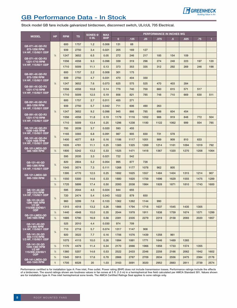
MODEL HP RPM TS SONES @ 0 IN.
MAX BHP
PERFORMANCE IN INCHES WG
0 .125 .25 .375 .5 .625 .75 1
GB-071-4X-QD-R2873-1256 RPM
1/4 HP, 115/60/1 ODP
GB-071-4X-QD-R31221-1710 RPM
1/4 HP, 115/60/1 ODP
1⁄4
600 1757 1.2 0.006 131 68
939 2750 3.4 0.021 205 169 127
1247 3652 6.5 0.05 272 246 217 185 154 109
1556 4558 9.3 0.098 339 319 296 274 248 223 197 120
1710 5009 11.1 0.13 373 353 335 312 292 269 246 198
GB-081-4X-QD-R2873-1256 RPM
1/4 HP, 115/60/1 ODP
GB-081-4X-QD-R31221-1710 RPM
1/4 HP, 115/60/1 ODP
1⁄4
600 1757 2.2 0.008 301 175
939 2750 4.7 0.031 470 404 330
1247 3652 7.6 0.073 625 575 525 470 403 284
1556 4558 10.8 0.14 779 740 700 660 615 571 517
1710 5009 12.5 0.19 856 821 785 748 710 669 630 511
GB-091-4X-QD-R2863-1256 RPM
1/4 HP, 115/60/1 ODP
GB-091-4X-QD-R31221-1710 RPM
1/4 HP, 115/60/1 ODP
1⁄4
600 1757 2.7 0.011 455 271
939 2750 5.7 0.042 711 606 490 263
1247 3652 9.2 0.098 945 866 785 698 604 454
1556 4558 11.8 0.19 1179 1116 1052 988 919 848 772 504
1710 5009 13.4 0.25 1296 1238 1180 1122 1062 999 934 785
GB-101-4X-QD-R31056-1400 RPM
1/4 HP, 115/60/1 ODP
GB-101-4X-QD-R41324-1688 RPM
1/4 HP, 115/60/1 ODP
GB-101-LMDX-QD588-1800 RPM
1⁄4
700 2039 3.7 0.020 593 455
1165 3393 6.8 0.091 987 905 830 731 578
1400 4077 8.9 0.16 1186 1117 1051 989 909 810 633
1635 4761 11.1 0.25 1385 1325 1269 1214 1161 1094 1019 792
1⁄3 1800 5242 13.2 0.33 1525 1471 1418 1367 1320 1270 1208 1064
GB-121-4X-QD980-1395 RPM
1/4 HP, 115/60/1 ODP
GB-121-LMDX-QD595-1550 RPM
1⁄4
595 2035 3.3 0.021 722 542
820 2804 5.2 0.054 995 877 728
1045 3574 7.3 0.111 1268 1177 1078 962 805
1395 4770 12.5 0.25 1692 1625 1557 1484 1404 1315 1214 907
1⁄3 1550 5300 14.6 0.33 1880 1820 1759 1696 1629 1555 1475 1289
1⁄2 1725 5899 17.4 0.50 2093 2038 1984 1928 1871 1810 1743 1600
GB-131-4X-QD942-1315 RPM
1/4 HP, 115/60/1 ODP
GB-131-5X-QD1299-1685 RPM
1/2 HP, 115/208-230/60/1
ODP
GB-131-LMDX-QD540-1685 RPM
1⁄4
595 2044 4.5 0.024 844 655
720 2474 5.4 0.043 1022 879 650
960 3299 7.6 0.103 1362 1262 1144 990
1315 4518 13.2 0.26 1866 1794 1718 1637 1545 1435 1305
1⁄3 1440 4948 15.0 0.35 2044 1978 1911 1838 1759 1674 1571 1299
1⁄2 1685 5790 16.9 0.56 2391 2335 2279 2219 2158 2093 2020 1857
GB-141-4X-QD614-865 RPM
1/4 HP, 115/60/1 ODP
GB-141-3X-QD906-1170 RPM
1/3 HP, 115/60/1 ODP
GB-141-5X-QD1049-1360 RPM
1/2 HP115/208-230/60/1
ODP
GB-141-LMDX-QD450-1545 RPM
1⁄4
525 2010 4.4 0.030 974 709
710 2718 5.7 0.074 1317 1147 908
920 3522 7.7 0.16 1706 1576 1439 1258 961
1075 4115 10.0 0.26 1994 1881 1771 1646 1489 1265
1⁄3 1170 4479 11.4 0.34 2170 2066 1966 1858 1733 1574 1355
1⁄2 1360 5207 14.6 0.53 2522 2433 2346 2258 2166 2062 1942 1602
3⁄4 1545 5915 17.6 0.78 2866 2787 2709 2634 2556 2475 2384 2176
1 1705 6528 20 1.03 3163 3091 3020 2952 2883 2811 2739 2574
GB Performance Data - In StockStock model GB fans include galvanized birdscreen, disconnect switch, UL/cUL 705 Electrical.

R O O F M O U N T E D F A N S 9
Performance certified is for installation type A: Free inlet, Free outlet. Power rating (BHP) does not include transmission losses. Performance ratings include the effects of a birdscreen. The sound ratings shown are loudness values in fan sones at 5 ft. (1.5 m) in a hemispherical free field calculated per AMCA Standard 301. Values shown are for installation type A: Free inlet hemispherical sone levels. The AMCA Certified Ratings Seal applies to sone ratings only.
MODEL HP RPM TS SONES @ 0 IN.
MAX BHP
PERFORMANCE IN INCHES WG
0 .125 .25 .375 .5 .625 .75 1 1.5 2
GB-161-5X-QD852-1100 RPM
1/2 HP 115/208-230/60/1 ODP
GB-161-LMDX-QD425-1375 RPM
1/4
478 2080 4.7 0.044 1412 1030
625 2720 6.4 0.097 1846 1574 1221
865 3764 10.6 0.26 2555 2359 2162 1932 1624
1⁄3 945 4113 12.6 0.34 2791 2612 2433 2236 2009 1692
1⁄2 1100 4787 15.3 0.53 3249 3094 2943 2786 2614 2428 2197
3⁄4 1250 5440 17.9 0.79 3692 3556 3421 3288 3149 2997 2838 2443
1 1375 5984 21 1.05 4062 3938 3815 3694 3571 3444 3304 3007 2073
GB-180-5X-QD676-940 RPM
1/2 HP115/208-230/60/1 ODP
GB-180-LMDX-QD495-1460 RPM
1⁄4495 2397 4.3 0.078 1924 1645 1150
730 3535 7.4 0.26 2838 2667 2469 2212 1882
1⁄3 810 3923 8.8 0.35 3149 2997 2832 2623 2375 2052
1⁄2 940 4552 12.7 0.55 3655 3526 3387 3234 3052 2843 2600
3⁄4 1055 5109 16.2 0.77 4102 3989 3866 3741 3596 3432 3251 2811
1 1185 5739 19.0 1.1 4607 4507 4400 4290 4179 4045 3900 3575
11⁄2 1335 6465 22 1.54 5191 5102 5010 4912 4814 4715 4599 4343
2 1460 7071 26 1.97 5677 5595 5514 5424 5335 5245 5155 4938 4426 3765
GB-200-LMDX-QD440-1200 RPM
1⁄4440 2462 6.5 0.103 2434 1975
600 3357 8.5 0.26 3320 2984 2637 2088
1⁄3 665 3721 9.6 0.35 3679 3378 3084 2705 2087
1⁄2 770 4308 12.1 0.55 4260 4013 3744 3477 3140 2643
3⁄4 860 4812 14.1 0.77 4759 4548 4289 4068 3810 3504 3085
1 965 5400 16.7 1.09 5340 5157 4927 4719 4519 4285 4015 3239
11⁄2 1090 6099 20 1.57 6031 5870 5681 5473 5301 5123 4924 4449
2 1200 6715 24 2.09 6640 6493 6336 6144 5968 5812 5650 5274 4177
GB-240-LMDX-QD300-910 RPM
1⁄4425 2726 5.9 0.21 3902 3422 2691
460 2950 6.7 0.26 4223 3784 3188 2036
1⁄3 505 3239 7.8 0.35 4636 4241 3760 3059
1⁄2 585 3752 10.3 0.55 5371 5030 4665 4194 3562 2112
3⁄4 660 4233 13.1 0.79 6059 5756 5449 5093 4636 4073 3217
1 730 4682 15.8 1.06 6702 6427 6157 5861 5506 5076 4567
11⁄2 825 5291 19.7 1.54 7574 7331 7091 6844 6573 6261 5901 5002
2 910 5836 24 2.06 8355 8134 7916 7699 7467 7214 6932 6240 3707
GB-300-LMDX-QD250-890 RPM
1⁄3300 2395 9.3 0.19 4859 3976
365 2914 9.2 0.35 5912 5222 4339
1⁄2 420 3353 9.6 0.53 6803 6221 5536 4640
3⁄4 475 3792 11.4 0.77 7694 7197 6615 5954 5094
1 530 4231 13.4 1.07 8584 8149 7639 7094 6455 5667 4194
11⁄2 600 4790 15.9 1.55 9718 9334 8906 8445 7951 7387 6721
2 665 5309 18.8 2.12 10771 10424 10059 9648 9228 8772 8268 7025
3 760 6068 23 3.15 12310 12007 11703 11357 10996 10629 10241 9369
5 890 7106 28 5.05 14416 14157 13897 13638 13335 13027 12716 12072 10536 7963
GB Performance Data - In StockStock model GB fans include galvanized birdscreen, disconnect switch, UL/cUL 705 Electrical.

R O O F M O U N T E D F A N S10
Greenheck Fan Corporation certifies that the Models LD, LDP, LB and LBP shown herein are licensed to bear the AMCA Seal. The ratings shown are based on tests and procedures performed in accordance with AMCA Publication 211 and AMCA Publication 311 and comply with the requirements of the AMCA Certified Ratings Program.
UL/cUL 705MH11745 - LD, LB, LDP & LBP
AC
B
A
D
1.75 in.
1.75 in.A
C
D
A
B
A
D
1.75 in.
B
LD/LDP DIRECT DRIVE CONDENSED PERFORMANCE RANGES & DIMENSIONAL DATA
All dimensions in inches. Dimension A - given is the inside dimensions of the curb cap. The roof curb should be 11/2 in. less than the curb cap to allow for roofing and flashing. Performance certified is for installation type A: Free inlet, Free outlet. Power rating (BHP) does not include transmission losses. Performance ratings include the effects of a birdscreen. The sound ratings shown are loudness values in fan sones at 5 ft. (1.5 m) in a hemispherical free field calculated per AMCA Standard 301. Values shown are for installation type A: Free inlet hemispherical sone levels. The AMCA Certified Ratings Seal applies to sone ratings only.
MODEL LD MODEL LDP
SERVICE CHART10
DAY
LD/LDP/LB/LBP - All models & sizes
✓
MODEL A sq.B C D ROOF
OPENINGDAMPER
SIZEMIN/MAX
RPMSONES @
0 IN.
PERFORMANCE IN INCHES WG
LD LDP LD LDP LD LDP 0 .125 .25 .375 .5 .625 .75
LD/LDP-60 17 22 23 27 23 13 131⁄2 101⁄2 x 101⁄2
8 x 8
1590 4.8 202 164 119
LD/LDP-65 17 22 23 27 23 13 131⁄2 101⁄2 x 101⁄2 1680 5.6 274 238 187 129
LD/LDP-70 17 22 23 27 23 13 131⁄2 101⁄2 x 101⁄2 1665 6.4 360 314 257 188
LD/LDP-75 17 22 23 27 23 13 131⁄2 101⁄2 x 101⁄2 1620 5.8 400 351 290 222
LD/LDP-80 19 28 25 27 25 16 161⁄2 121⁄2 x 121⁄2
10 x 10
1550 8.8 481 413 342 258
LD/LDP-85 19 28 25 27 25 16 161⁄2 121⁄2 x 121⁄2 1500 8.6 576 490 403 291
LD/LDP-90 19 28 25 27 25 16 161⁄2 121⁄2 x 121⁄2 1550 8.8 819 714 608 485 361
LD/LDP-95 19 28 25 27 25 16 161⁄2 121⁄2 x 121⁄2 1550 11.8 1052 942 825 695 552 396
LD/LDP-100 22 30 28 27 28 18 181⁄2 141⁄2 x 141⁄2
12 x 12
860 6.3 767 568
1725 16.2 1538 1458 1361 1256 1142 1024 891
LD/LDP-120 22 30 28 27 28 18 181⁄2 141⁄2 x 141⁄2860 6.6 921 703
1725 21 1848 1762 1652 1540 1412 1286 1143
Low Silhouette Roof Exhaust - LD/LDP Models LD and LB are available in Fabra Style hoods and Models LDP and LBP are available in louvered penthouse hoods. These fans offer attractive appearance combined with rugged construction, high performance, and low sound level. Fan wheels shall be centrifugal, backward-inclined and constructed of aluminum. Model LD and LDP Roof Exhaust fans are centrifugal direct drive.
Model LB and LBP roof exhaust fans are centrifugal belt drive. Adjustable motor pulleys allow for final system balancing.
PERFORMANCEModels LD and LDP performance capabilities range from 79 cfm to 1,848 cfm and up to 0.75 in. wg of static pressure.
Model LB and LBP performance capabilities range from 351cfm to 37,000 cfm and up to 1.25 in. wg of static pressure.
For complete product information refer to catalog Model LD/LDP & LB/LBP, or contact your local representative.

R O O F M O U N T E D F A N S 11
All dimensions in inches. Dimension A - given is the inside dimensions of the curb cap. The roof curb should be 11/2 in. less than the curb cap to allow for roofing and flashing. Performance certified is for installation type A: Free inlet, Free outlet. Power rating (BHP) does not include transmission losses. Performance ratings include the effects of a birdscreen. The sound ratings shown are loudness values in fan sones at 5 ft. (1.5 m) in a hemispherical free field calculated per AMCA Standard 301. Values shown are for installation type A: Free inlet hemispherical sone levels. The AMCA Certified Ratings Seal applies to sone ratings only.
LBP BELT DRIVE CONDENSED PERFORMANCE RANGES & DIMENSIONAL DATA
1.75 in.
E
A
C
D
A
B
MODEL LB
A
C
B
A
D
1.75 in.
MODEL LBP
MODEL A B C D E ROOF OPENING
DAMPER SIZE
MIN/MAX RPM
SONES @ 0 IN.
PERFORMANCE IN INCHES WG0 .125 .25 .5 .75 1
LB-10 22 x 22 28 39 17 31⁄4 141⁄2 x 141⁄2 12 x 12 600 3.0 539 3511767 13.5 1587 1533 1480 1385 1254 1112
LB-14 26 x 26 35 39 18 4 181⁄2 x 181⁄2 16 x 16 480 4.1 903 6141343 14.4 2525 2456 2372 2199 1979 1692
LB-18 30 x 30 40 39 21 41⁄2 201⁄2 x 201⁄218 x 18
465 3.6 1753 14221460 26 5505 5417 5328 5138 4936 4714
LB-21 30 x 30 43 51 23 6 201⁄2 x 201⁄2 465 6.6 2820 2420 17321200 26 7278 7156 7034 6712 6375 5954
LB-24 34 x 34 451⁄2 51 231⁄2 63⁄4 261⁄2 x 261⁄2 24 x 24 355 5.8 3419 2806910 27 8763 8549 8333 7889 7377 6713
LB-30 40 x 40 50 63 265⁄8 81⁄2 321⁄2 x 321⁄2 30 x 30 230 8.0 3910 2576835 27 14194 13914 13635 13062 12432 11728
LB-36 46 x 46 60 63 325⁄8 93⁄4 381⁄2 x 381⁄2 36 x 36 220 4.9 6204 4803678 30 19121 18770 18419 17621 16683 15636
LB-42 52 x 52 705⁄8 75 373⁄8 111⁄2 441⁄2 x 441⁄2 42 x 42 190 5.2 8328 6455515 25 22574 22037 21500 20214 18651 16871
LB-48 58 x 58 705⁄8 87 411⁄2 115⁄8 501⁄2 x 501⁄2 48 x 48 150 6.1 9666 6546420 23 27065 26278 25383 23363 21159 18029
LB-54 64 x 64 791⁄2 87 453⁄8 121⁄2 561⁄2 x 561⁄2 54 x 54 130 4.6 12159401 25 37506 36544 35583 33500 30332 26018
MODEL A B C D ROOF OPENING
DAMPER SIZE
MIN/MAX RPM
SONES @ 0 IN.
PERFORMANCE IN INCHES WG0 .125 .25 .5 .75 1
LBP-10 22 x 225⁄8 28 381⁄2 17 141⁄2 x 141⁄2 12 x 12 600 3.0 539 3511767 13.5 1587 1533 1480 1385 1254 1112
LBP-14 26 x 26 32 40 17 181⁄2 x 181⁄2 16 x 16 480 4.1 903 6141343 14.4 2525 2456 2372 2199 1979 1692
LBP-18 30 x 30 36 46 241⁄2 201⁄2 x 201⁄218 x 18
465 3.6 1753 14221460 26 5505 5417 5328 5138 4936 4714
LBP-21 30 x 30 36 46 241⁄2 201⁄2 x 201⁄2 465 6.6 2820 2420 17321200 26 7278 7156 7034 6712 6375 5954
LBP-24 34 x 34 40 491⁄2 231⁄2 261⁄2 x 261⁄2 24 x 24 355 5.8 3419 2806910 27 8763 8549 8333 7889 7377 6713
LBP-30 40 x 40 46 58 261⁄2 321⁄2 x 321⁄2 30 x 30 230 8.0 3910 2576835 27 14194 13914 13635 13062 12432 11728
LBP-36 46 x 46 513⁄4 63 343⁄8 381⁄2 x 381⁄2 36 x 36 220 4.9 6204 4803678 30 19121 18770 18419 17621 16683 15636
LBP-42 52 x 52 58 701⁄2 381⁄4 441⁄2 x 441⁄2 42 x 42 190 5.2 8328 6455515 25 22574 22037 21500 20214 18651 16871
LBP-48 58 x 58 64 761⁄2 403⁄8 501⁄2 x 501⁄2 48 x 48 150 6.1 9666 6546420 23 27065 26278 25383 23363 21159 18029
LBP-54 64 x 64 70 831⁄2 435⁄8 561⁄2 x 561⁄2 54 x 54 130 4.6 12159401 25 37506 36544 35583 33500 30332 26018
Low Silhouette Roof Exhaust - LB/LBP
STANDARD CONSTRUCTION FEATURES• Aluminumhousingwithhingedhood• Non-overloadingbackward-inclinedaluminumwheel• Curbcapwithprepunchedmountingholes• Motoranddrivesisolatedonshockmounts• Birdscreenmountedtothedischargeperimeter• Ballbearingmotors• Adjustablemotorpulley• Adjustablemotorplate• Fanshaftmountedinballbearingpillowblocks• Staticfreebelts• Corrosion-resistantfasteners• NEMA-1disconnect
OPTIONS AND ACCESSORIES • Galvanizedhousing• Performancebaffle(Directdrivemodels)• Gravityandmotorizeddampers• Galvanizedandaluminumroofcurbs
(See pages 38-39)• Curbseal• Curbadaptors• Aluminumbirdscreen• Speedcontrol(Directdrivemodels)• Relubricatablebearings• UL/cUL705Electrical• DualDrives• NEMA-3RandEXPdisconnectswitches• Greenheckcoatings(See coatings page 119)
LB BELT DRIVE CONDENSED PERFORMANCE RANGES & DIMENSIONAL DATA

R O O F M O U N T E D F A N S12
B
C*
A
13/4
"D
in.
Greenheck Fan Corporation certifies that the Model CUE fans shown herein are licensed to bear the AMCA Seal. The ratings shown are based on tests and procedures performed in accordance with AMCA Publication 211 and Publication 311 and comply with the requirements of the AMCA Certified Ratings Program.
*May be greater depending on motor. All dimensions in inches.^Dampers should not be used in grease applications.Dimension A - given is the inside dimensions of the curb cap.The roof curb should be 11/2 in. less than the curb cap to allow for roofing and flashing.Performance certified is for installation type A: Free inlet, Free outlet. Power rating (BHP) does not include transmission losses. Performance ratings do not include the effects of appurtenances (accessories). The sound ratings shown are loudness values in fan sones at 5 ft. (1.5 m) in a hemispherical free field calculated per AMCA Standard 301. Values shown are for installation type A: Free inlet hemispherical sone levels. The AMCA Certified Ratings Seal applies to sone ratings only.
n Performance for available in stock sizes is shown on page 13
UL/cUL 705UL/cUL 762 (size 98 and up)E40001 - CUE
MODEL A B C* D ROOF OPENING
DAMPER SIZE ^
IN STOCK SIZES (n)
MIN/MAX RPM
SONES @ 0 IN.
PERFORMANCE IN INCHES WG0 .125 .25 .5 .75 1.5
CUE-060 17 183⁄8 131⁄2 113⁄8 101⁄2 x 101⁄2
8 x 8
1050 1.7 133 811550 4.2 197 164 128
CUE-065 17 183⁄8 131⁄2 113⁄8 101⁄2 x 101⁄2 1050 2.2 180 1091550 4.7 266 222 172
CUE-070 17 183⁄8 131⁄2 113⁄8 101⁄2 x 101⁄2 1050 2.6 250 1711550 5.5 369 325 269
CUE-075 17 183⁄8 131⁄2 113⁄8 101⁄2 x 101⁄2 1050 3.4 287 1881550 6.0 424 359 291
CUE-080 19 21 133⁄8 111⁄2 121⁄2 x 121⁄2
10 x 10
1050 3.8 325 247 1331550 7.3 480 431 376 235
CUE-085 19 21 133⁄8 111⁄2 121⁄2 x 121⁄2 1050 4.0 389 305 1821550 7.5 574 520 461 312
CUE-090 19 21 133⁄8 111⁄2 121⁄2 x 121⁄2 1050 4.1 549 451 3061550 7.8 811 744 677 501
CUE-095 19 21 151⁄4 137⁄16 121⁄2 x 121⁄2 1050 5.3 711 570 3811550 9.6 1049 964 861 616
CUE-098 19 247⁄8 281⁄4 173⁄8 141⁄2 x 141⁄2
12 x 12
860 8.4 588 4091725 13.8 1180 1094 1017 824 586
CUE-101 19 247⁄8 281⁄4 173⁄8 141⁄2 x 141⁄2 n860 4.6 732 625 481
1725 13.3 1468 1422 1373 1255 1129
CUE-121 19 247⁄8 281⁄4 173⁄8 141⁄2 x 141⁄2 n860 5.3 1015 905 781
1725 15.6 2037 1979 1923 1816 1710 1176
CUE-131 19 247⁄8 281⁄4 173⁄8 141⁄2 x 141⁄2 860 8.5 1180 1057 9141725 18.8 2366 2305 2244 2122 1994
CUE-141 22 287⁄8 293⁄4 193⁄8 181⁄2 x 181⁄216 x 16
860 7.3 1558 1427 12641725 26 3125 3066 3005 2865 2711 2085
CUE-161 22 287⁄8 293⁄4 193⁄8 181⁄2 x 181⁄2 860 10.7 2472 2315 2126 16801725 30 4959 4882 4806 4646 4463 3855
CUE-180 30 233⁄8 285⁄8 21 201⁄2 x 201⁄218 x 18
860 12.3 3249 3074 2922 24741140 17.6 4307 4173 4045 3822 3470
CUE-200 30 233⁄8 285⁄8 21 201⁄2 x 201⁄2 860 15.7 4837 4587 4346 3815 30841140 24 6412 6224 6036 5674 5283 3445
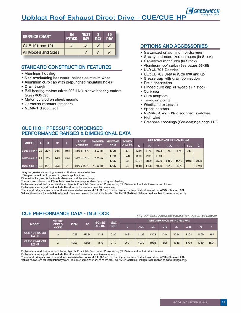
Upblast Roof Exhaust Direct Drive - CUE/CUE-HPModel CUE centrifugal roof exhaust fans are direct drive. These fans are specifically designed for roof mounted applications. Exhaust air is discharged directly upward, away from the roof surface. Fan wheels are centrifugal, backward-inclined and constructed of aluminum.
PERFORMANCEPerformance capabilities range from 130 cfm to 6,410 cfm and up to 1.5 in. wg of static pressure.
CUE CONDENSED PERFORMANCE RANGES & DIMENSIONAL DATA
For complete product information refer to catalog Series C, or contact your local representative.
R O O F M O U N T E D F A N S 13
Performance certified is for installation type A: Free inlet, Free outlet. Power rating (BHP) does not include drive losses. Performance ratings do not include the effects of appurtenances (accessories). The sound ratings shown are loudness values in fan sones at 5 ft. (1.5 m) in a hemispherical free field calculated per AMCA Standard 301. Values shown are for installation type A: Free inlet hemispherical sone levels. The AMCA Certified Ratings Seal applies to sone ratings only.
*May be greater depending on motor. All dimensions in inches.^Dampers should not be used in grease applications.Dimension A - given is the inside dimensions of the curb cap.The roof curb should be 11/2 in. less than the curb cap to allow for roofing and flashing.Performance certified is for installation type A: Free inlet, Free outlet. Power rating (BHP) does not include transmission losses. Performance ratings do not include the effects of appurtenances (accessories). The sound ratings shown are loudness values in fan sones at 5 ft. (1.5 m) in a hemispherical free field calculated per AMCA Standard 301. Values shown are for installation type A: Free inlet hemispherical sone levels. The AMCA Certified Ratings Seal applies to sone ratings only.
CUE HIGH PRESSURE CONDENSED PERFORMANCE RANGES & DIMENSIONAL DATA
MODELMOTOR
SPEED CODE
RPM TS SONES @ 0 IN.
MAX BHP
PERFORMANCE IN INCHES WG
0 .125 .25 .375 .5 .625 .75 1
CUE-101-AX-QD1/4 HP A 1725 5024 13.3 0.29 1468 1422 1372 1314 1254 1194 1129 969
CUE-121-AX-QD1/2 HP A 1725 5899 15.6 0.47 2037 1979 1923 1869 1816 1763 1710 1571
in stock sizes include disconnect switch, UL/cUL 705 electrical.
MODEL A B C* D ROOF OPENING
DAMPER SIZE^
MIN/MAX RPM
SONES @ 0.5 IN.
PERFORMANCE IN INCHES WG
.5 .75 1 1.25 1.5 1.75 2
CUE-141HP 22 227⁄8 243⁄4 193⁄8 181⁄2 x 181⁄2 16 x 16 1725 16.1 1256 1178 1098 999 879 747
CUE-161HP 22 287⁄8 243⁄4 193⁄8 181⁄2 x 181⁄2 16 x 161140 12.5 1645 1444 1175
1725 22 2787 2680 2560 2439 2310 2167 2003
CUE-180HP 30 233⁄8 255⁄8 21 201⁄2 x 201⁄2 18 x 18 1725 28 4613 4493 4353 4215 4078 3740
Upblast Roof Exhaust Direct Drive - CUE/CUE-HP
STANDARD CONSTRUCTION FEATURES• Aluminumhousing• Non-overloadingbackward-inclinedaluminumwheel• Aluminumcurbcapwithprepunchedmountingholes• Draintrough• Ballbearingmotors(sizes098-161),sleevebearingmotors
(sizes 060-095)• Motorisolatedonshockmounts• Corrosion-resistantfasteners• NEMA-1disconnect
OPTIONS AND ACCESSORIES • Galvanizedoraluminumbirdscreen• Gravityandmotorizeddampers(InStock)• Galvanizedroofcurbs(InStock)• Aluminumroofcurbs(Seepages38-39)• UL/cUL705Electrical• UL/cUL762Grease(Size098andup)• Greasetrapwithdrainconnection• Drainconnection• Hingedcurbcapkitw/cable(Instock)• Curbseal• Curbadaptors• Tie-downpoints• Windbandextension• Speedcontrols• NEMA-3RandEXPdisconnectswitches• Highwind• Greenheckcoatings(See coatings page 119)
CUE PERFORMANCE DATA - IN STOCK
SERVICE CHART IN STOCK
NEXT DAY
3 DAY
10 DAY
CUE-101 and 121 ✓ ✓ ✓ ✓
All Models and Sizes ✓ ✓ ✓

R O O F M O U N T E D F A N S14
For complete product information refer to catalog Series C, or contact your local representative.
B
C*D
A
13/4 in.
Greenheck Fan Corporation certifies that the Model CUBE fans shown herein are licensed to bear the AMCA Seal. The ratings shown are based on tests and procedures performed in accordance with AMCA Publication 211 and Publication 311 and comply with the requirements of the AMCA Certified Ratings Program.
*May be greater depending on motor. All dimensions in inches.^Dampers should not be used in grease applications.Dimension A - given is the inside dimensions of the curb cap.The roof curb should be 11/2 in. less than the curb cap to allow for roofing and flashing.Performance certified is for installation type A: Free inlet, Free outlet. Power rating (BHP) does not include transmission losses. Performance ratings do not include the effects of appurtenances (accessories). The sound ratings shown are loudness values in fan sones at 5 ft. (1.5 m) in a hemispherical free field calculated per AMCA Standard 301. Values shown are for installation type A: Free inlet hemispherical sone levels. The AMCA Certified Ratings Seal applies to sone ratings only.
CUBE CONDENSED PERFORMANCE RANGES & DIMENSIONAL DATA n Performance for available in stock sizes is shown on pages 16 & 17
UL/cUL 705UL/cUL 762MH 11745-CUBE
MODEL A B C* D ROOF OPENING
DAMPER SIZE^
IN STOCK SIZES (n)
MIN/MAX RPM
SONES @ 0 IN.
PERFORMANCE IN INCHES WG0 .25 .5 .75 1 2
CUBE-098 19 247⁄8 281⁄4 173⁄8 141⁄2 x 141⁄2
12 x 12
n650 8.1 445
1725 13.8 1180 1017 824 586
CUBE-101 19 247⁄8 281⁄4 173⁄8 141⁄2 x 141⁄2 n860 4.6 732 625 481
1820 14.3 1549 1459 1350 1234 1106
CUBE-121 19 247⁄8 281⁄4 173⁄8 141⁄2 x 141⁄2 n685 4.4 809
1725 15.6 2037 1923 1816 1710 1571
CUBE-131 19 247⁄8 281⁄4 173⁄8 141⁄2 x 141⁄2650 6.2 892
1645 17.9 2256 2128 2001 1864 1684
CUBE-141 22 287⁄8 293⁄4 193⁄8 181⁄2 x 181⁄216 x 16
n590 5.0 1069
1725 26 3125 3005 2865 2711 2539
CUBE-161 22 287⁄8 293⁄4 193⁄8 181⁄2 x 181⁄2 n730 8.1 2098 16691390 22 3996 3806 3584 3340 3078
CUBE-180 30 353⁄8 285⁄8 21 201⁄2 x 201⁄218 x 18
n630 7.1 2380 18611495 28 5648 5443 5254 5082 4921 3564
CUBE-200 30 353⁄8 285⁄8 21 201⁄2 x 201⁄2 n500 6.2 2812 18221210 25 6806 6451 6108 5748 5350
CUBE-220 34 423⁄4 337⁄8 251⁄2 261⁄2 x 261⁄224 x 24
450 7.3 3585 2624955 25 7607 7202 6799 6347 5844
CUBE-240 34 423⁄4 337⁄8 251⁄2 261⁄2 x 261⁄2 n410 6.4 3717 2471930 24 8431 7985 7536 6953 6375
CUBE-300 40 50 36 29 321⁄2 x 321⁄2 30 x 30 n355 6.9 5777 4227905 32 14727 14266 13788 13223 12614 9178
CUBE-360 46 565⁄8 391⁄8 293⁄8 381⁄2 x 381⁄2 36 x 36300 6.9 8092 6023690 30 18611 17884 17115 16236 15243
CUBE-420 52 653⁄8 443⁄4 351⁄4 441⁄2 x 441⁄2 42 x 42220 6.5 9353 5075600 29 25508 24604 23451 22295 21023
CUBE-480 58 743⁄16 481⁄8 36 501⁄2 x 501⁄2 48 x 48180 5.5 11016490 28 29988 28697 27291 25704 23674
Upblast Roof Exhaust Belt Drive - CUBEModel CUBE centrifugal roof exhaust fans are belt drive. These fans are specifically designed for roof mounted applications. Exhaust air is discharged directly upward, away from the roof surface. Fan wheels are centrifugal, backward-inclined, and constructed of aluminum. Adjustable motor pulleys allow for final system balancing.
PERFORMANCEPerformance capabilities range from 258 cfm to 30,000 cfm and up to 5 in. wg of static pressure.

R O O F M O U N T E D F A N S 15
CUBE HIGH PRESSURE CONDENSED PERFORMANCE RANGES & DIMENSIONAL DATA n Performance for available in stock sizes is shown on page 17
CUBE ExTENDED PRESSURE CONDENSED PERFORMANCE RANGES & DIMENSIONAL DATA in stock sizes not available for extended Pressure
*May be greater depending on motor. All dimensions in inches. Dimension A - given is the inside dimensions of the curb cap.^Dampers should not be used in grease applications.The roof curb should be 11/2 in. less than the curb cap to allow for roofing and flashing. Performance certified is for installation type A: Free inlet, Free outlet. Power rating (BHP) does not include transmission losses. Performance ratings do not include the effects of appurtenances (accessories). The sound ratings shown are loudness values in fan sones at 5 ft. (1.5 m) in a hemispherical free field calculated per AMCA Standard 301. Values shown are for installation type A: Free inlet hemispherical sone levels. The AMCA Certified Ratings Seal applies to sone ratings only.
SERVICE CHART IN STOCK
NEXT DAY
3 DAY
10 DAY
CUBE-098 through 121, 141 through 240 & 300 ✓ ✓ ✓ ✓
CUBE-098 through 480 ✓ ✓ ✓
High Pressure CUBE-141HP through 180HP & 240HP ✓ ✓ ✓ ✓
High Pressure CUBE-101HP through 360HP ✓ ✓ ✓
Extended Pressure CUBE-161xP through 360xP ✓ ✓ ✓
MODEL A B C* D ROOF OPENING
DAMPER SIZE^
IN STOCK
SIZES (n)
MIN/MAX RPM
SONES @ 0.5 IN.
PERFORMANCE IN INCHES WG
.5 .75 1.25 1.75 2.25 2.75
CUBE-101HP 19 247⁄8 281⁄4 173⁄8 141⁄2 x 141⁄2 12 x 12 1300 6.0 3352580 16.8 1014 969 861 735 550
CUBE-141HP 22 287⁄8 293⁄4 193⁄8 181⁄2 x 181⁄216 x 16
n895 6.1 331
2110 19.8 1592 1536 1409 1262 1073 804CUBE-161HP 22 287⁄8 293⁄4 193⁄8 181⁄2 x 181⁄2 825 7.0 889
1690 21 2722 2611 2365 2082 1664CUBE-180HP 30 353⁄8 285⁄8 21 201⁄2 x 201⁄2
18 x 18n
795 8.3 15701685 27 4495 4369 4085 3768 3325 2766
CUBE-200HP 30 353⁄8 285⁄8 21 201⁄2 x 201⁄2 740 8.1 20241600 29 5943 5775 5385 4971 4476 3760
CUBE-220HP 34 423⁄4 337⁄8 251⁄2 261⁄2 x 261⁄224 x 24
650 8.6 2909 19401240 26 6895 6684 6217 5637 4885 3633
CUBE-240HP 34 423⁄4 337⁄8 251⁄2 261⁄2 x 261⁄2 n635 8.1 3046
1230 26 7513 7280 6730 6090 5326CUBE-300HP 40 50 36 29 321⁄2 x 321⁄2 30 x 30 460 7.3 3125
1045 35 10909 10570 9855 9054 8002 6463CUBE-360HP 46 585⁄8 391⁄8 293⁄8 381⁄2 x 381⁄2 36 x 36 420 9.6 6407
865 33 17129 16631 15544 14315 12738 10197
MODEL A B C* D ROOF OPENING
DAMPER SIZE ^
MIN/MAX RPM
SONES @ 0 IN.
PERFORMANCE IN INCHES WG
1 1.5 2 3 4 5
CUBE-161XP 22 287⁄8 293⁄4 193⁄8 181⁄2 x 181⁄2 16 x 161550 10.0 968
2525 22 2339 2155 1946 1221
CUBE-240XP 34 423⁄4 337⁄8 251⁄2 261⁄2 x 261⁄2 24 x 241100 10.9 1292
2165 29 3927 3733 3535 3063 2461 1324
CUBE-300XP 40 50 36 29 321⁄2 x 321⁄2 30 x 30790 9.4 1776
1690 36 7643 7284 6920 6091 4951
CUBE-360XP 46 585⁄8 391⁄8 293⁄8 381⁄2 x 381⁄2 36 x 36700 10.5 3210
1490 33 10699 10294 9871 8907 7673 5830
Upblast Roof Exhaust Belt Drive - CUBE
STANDARD CONSTRUCTION FEATURES• Aluminumhousing• Non-overloadingbackward-inclined
aluminum wheel• Curbcapwithprepunchedmountingholes• Motoranddrivesisolatedonshockmounts• Draintrough• Ballbearingmotors• Adjustablemotorpulley• Adjustablemotorplate• Fanshaftmountedinballbearings• Static-resistantbelts• Corrosion-resistantfasteners• NEMA-1disconnect
• Galvanizedbirdscreen(Instock)• Aluminumbirdscreen• Gravityandmotorizeddampers
for non-UL/cUL 762 applications (In Stock)
• Galvanizedroofcurbs(Instock)• Aluminumroofcurbs(Seepages
38-39)• Ventedcurbextensions(See
pages 38-39)• Heatbaffles• UL/cUL705Electrical• UL/cUL762Grease• Nonstickwheels• Cleanoutport
• Drainconnection• Greasetrapw/drainconnection• Hingedcurbcapkitw/cable(In
stock)• Curbseal• Curbadaptors• Windbandextension• Tie-downpoints• Relubricatablebearings• Dualdrives• NEMA-3RandEXPdisconnect
switches• Highwind• Greenheckcoatings(See
coatings page 119)
OPTIONS AND ACCESSORIES

R O O F M O U N T E D F A N S16
MODEL HP RPM TS SONES @ 0 IN.
MAXBHP
PERFORMANCE IN INCHES WG
0 .125 .25 .375 .5 .625 .75 1
CUBE-098-4G-QD1259-1725 RPM
1/4 HP, 115/60/1 ODP1⁄4
1160 3302 9.2 0.006 793 672 522
1330 3786 10.7 0.09 909 804 689 361
1550 4412 13.0 0.14 1060 966 878 644 502
CUBE-101-4G-QD1191-1660 RPM
1/4 HP, 115/60/1 ODP
CUBE-101-3G-QD1408-1820 RPM
1/3 HP, 115/208-230/60/1 ODP
CUBE-101-LMDG-QD960-1820 RPM
1⁄4
860 2505 4.6 0.04 732 625 481
1205 3509 7.7 0.100 1025 957 873 782 662
1660 4834 12.7 0.26 1413 1364 1313 1251 1189 1125 1056 861
1⁄3 1820 5300 14.3 0.35 1549 1505 1458 1406 1350 1293 1234 1106
CUBE-121-3G-QD1068-1545 RPM
1/3 HP, 115/230/60/1 ODP
CUBE-121-LMDG-QD685-1545 RPM
1⁄4
685 2342 4.4 0.029 808 669
845 2889 5.3 0.056 997 885 757
1045 3573 6.5 0.105 1233 1141 1053 944 798
1410 4821 11.1 0.26 1664 1594 1528 1463 1398 1315 1224 965
1⁄3 1545 5283 12.8 0.34 1824 1760 1698 1639 1580 1518 1441 1262
CUBE-141-5G-QD951-1400 RPM
1/2 HP, 115/208-230/60/1 ODP
CUBE-141-7G-QD1215-1595 RPM
3/4 HP, 115/208-230/60/1 ODP
CUBE-141-LMDG-QD590-1595 RPM
1⁄4590 2259 5.0 0.040 1068 851
1105 4230 10.9 0.26 2001 1905 1792 1667 1515 1318 998
1⁄3 1210 4632 12.2 0.34 2191 2106 2006 1896 1772 1628 1442
1⁄2 1390 5322 14.9 0.52 2517 2445 2361 2271 2173 2068 1949 1642
3/4 1595 6106 20 0.79 2889 2825 2757 2683 2601 2517 2429 2225
CUBE-161-7G-QD935-1265 RPM
3/4 HP, 115/208-230/60/1 ODP
CUBE-161-LMDG-QD730-1390 RPM
1⁄4730 3177 8.1 0.15 2098 1904 1669 1389
875 3808 11.0 0.26 2515 2361 2177 1974 1743 1364
1⁄3 965 4200 12.4 0.35 2774 2637 2476 2300 2109 1893 1583
1⁄2 1110 4831 15.0 0.54 3190 3072 2940 2796 2640 2475 2297 1770
3⁄4 1265 5505 18.5 0.79 3636 3532 3425 3301 3172 3035 2893 2582
1 1390 6049 22 1.05 3995 3900 3806 3698 3584 3464 3340 3078
CUBE-180-LMDG-QD630-1495 RPM
1⁄4630 3051 7.1 0.16 2380 2154 1861 1403
745 3608 9.2 0.26 2814 2616 2448 2143 1763
1⁄3 820 3971 11.2 0.34 3097 2915 2759 2525 2257 1866
1⁄2 940 4552 13.8 0.52 3551 3388 3243 3115 2879 2654 2363
3⁄4 1075 5206 16.5 0.78 4061 3919 3786 3666 3554 3344 3141 2652
1 1185 5739 18.5 1.04 4476 4347 4223 4108 4005 3903 3702 3336
11⁄2 1360 6586 23 1.58 5137 5025 4913 4811 4710 4620 4531 4232
2 1495 7240 28 2.10 5647 5545 5443 5345 5253 5162 5082 4921
CUBE-200-LMDG-QD500-1210 RPM
1⁄4500 2797 6.2 0.15 2812 2386 1821
605 3385 8.1 0.26 3402 3054 2674 2144
1⁄3 665 3721 9.4 0.35 3740 3421 3095 2699 2072
1⁄2 760 4252 12.1 0.52 4274 3993 3718 3413 3048 2517
3⁄4 875 4896 16.3 0.79 4921 4676 4438 4192 3922 3626 3240
1 960 5372 18.7 1.04 5399 5175 4957 4742 4508 4253 3985 3168
11⁄2 1100 6155 23 1.57 6187 5991 5798 5610 5420 5216 5006 4528
2 1210 6771 25 2.09 6805 6628 6450 6279 6108 5932 5747 5349
CUBE Performance Data - In StockStock model CUBE fans include disconnect switch, UL/cUL 762 label and heat baffle.
Performance certified is for installation type A: Free inlet, Free outlet. Power rating (BHP) does not include transmission losses. Performance ratings do not include the effects of appurtenances (accessories). The sound ratings shown are loudness values in fan sones at 5 ft. (1.5 m) in a hemispherical free field calculated per AMCA Standard 301. Values shown are for installation type A: Free inlet hemispherical sone levels. The AMCA Certified Ratings Seal applies to sone ratings only.

R O O F M O U N T E D F A N S 17
Performance certified is for installation type A: Free inlet, Free outlet. Power rating (BHP) does not include transmission losses. Performance ratings do not include the effects of appurtenances (accessories). The sound ratings shown are loudness values in fan sones at 5 ft. (1.5 m) in a hemispherical free field calculated per AMCA Standard 301. Values shown are for installation type A: Free inlet hemispherical sone levels. The AMCA Certified Ratings Seal applies to sone ratings only.
MODEL HP RPM TS SONES @ 0 IN.
MAX BHP
PERFORMANCE IN INCHES WG0 .125 .25 .375 .5 .625 .75 1
CUBE-240-LMDG-QD 410-930 RPM
1⁄4410 2629 6.4 0.18 3716 3169 2471
465 2982 7.6 0.26 4215 3767 3187 21621⁄3 510 3271 8.9 0.34 4623 4242 3716 31341⁄2 585 3752 11.5 0.51 5303 4960 4539 4093 35653⁄4 670 4297 14.3 0.79 6073 5762 5460 5052 4059 4202 3524
1 735 4714 16.6 1.04 6663 6370 6133 5764 5409 5037 4618
11⁄2 845 5419 19.6 1.58 7660 7399 7183 6947 6615 6304 6002 5282
2 930 5965 24 2.10 8431 8194 7985 7798 7536 7233 6953 6375
CUBE-300-LMDG-QD355-905 RPM
1⁄3355 2834 6.9 0.31 5777 5131 4226
365 2914 7.2 0.34 5939 5316 44631⁄2 420 3353 9.0 0.52 6834 6314 5659 48203⁄4 480 3832 11.0 0.77 7811 7376 6844 6231 5440
1 530 4231 13.3 1.05 8624 8231 7771 7245 6636 5879
11⁄2 605 4830 17.0 1.56 9845 9500 9127 8705 8226 7707 7083
2 665 5309 20 2.07 10821 10508 10192 9410 8967 8495 7270
3 765 6108 24 3.15 12449 12176 11903 11607 11273 10938 10553 9743
5 905 7226 32 5.19 14727 14496 14266 14036 13788 13505 13203 12614
MODEL HP RPM TS SONES @ 0.5 IN.
MAXBHP
PERFORMANCE IN INCHES WG
.5 .75 1 1.25 1.5 1.75 2 2.25 2.5
CUBE-141HP-LMDG-QD895-2110 RPM
1⁄4895 3426 6.1 0.055 330
1465 5609 14.2 0.26 1015 920 797 642
1⁄3 1605 6145 15.2 0.34 1146 1062 965 845 703
1⁄2 1845 7064 17.0 0.52 1363 1292 1218 1136 1041 923 800
3⁄4 2110 8078 19.8 0.78 1592 1535 1472 1408 1341 1261 1178 1073 965
CUBE-180HP-LMDG-QD795-1685 RPM
1⁄4 795 3850 8.3 0.22 1570
1⁄3 925 4480 10.8 0.35 2104 1687
1⁄2 1065 5158 13.8 0.53 2581 2323 1932
3⁄4 1215 5884 15.0 0.79 3062 2867 2626 2286 1853
1 1335 6465 18.7 1.04 3440 3260 3075 2839 2523 2155
11⁄2 1530 7410 24 1.57 4034 3884 3728 3574 3375 3134 2859 2533
2 1685 8160 27 2.09 4495 4369 4225 4085 3945 3767 3574 3324 3061
CUBE-240HP-LMDG-QD635-1230 RPM
1⁄2 675 4329 9.4 0.52 3405 2606
3⁄4 775 4970 13.1 0.78 4232 3704 2940
1 850 5451 14.5 1.04 4811 4367 3845 3024
11⁄2 975 6253 18.4 1.56 5736 5386 4988 4538 4005
2 1070 6863 22 2.08 6404 6112 5774 5407 4990 4549 3624
3 1230 7889 26 3.16 7513 7279 7016 6729 6409 6090 5709 5325 4721
CUBE Performance Data - In StockStock model CUBE fans include disconnect switch, UL/cUL 762 label and heat baffle.
CUBE-HP Performance Data - In StockStock Model CUBE-HP fans include disconnect switch, UL/cUL 762 label and heat baffle.

R O O F M O U N T E D F A N S18
Greenheck Fan Corporation certifies that the Model USGF fan shown herein is licensed to bear the AMCA Seal. The ratings shown are based on tests and procedures performed in accordance with AMCA Publication 211 and Publication 311 and comply with the requirements of the AMCA Certified Ratings Program.
USGF STANDARD PERFORMANCE RANGES & DIMENSIONAL DATA
HIGH PRESSURE PERFORMANCE RANGES & DIMENSIONAL DATA
B
C*D
A
13/4 in.
ExTENDED PRESSURE PERFORMANCE RANGES & DIMENSIONAL DATA
*May be greater depending on motor. All dimensions in inches. Dimension A - given is the inside dimensions of the curb cap.The roof curb should be 11/2 in. less than the curb cap to allow for roofing and flashing. Performance certified is for installation type A: Free inlet, Free outlet. Power rating (BHP) does not include transmission losses. Performance ratings do not include the effects of appurtenances (accessories). The sound ratings shown are loudness values in fan sones at 5 ft. (1.5 m) in a hemispherical free field calculated per AMCA Standard 301. Values shown are for installation type A: Free inlet hemispherical sone levels. The AMCA Certified Ratings Seal applies to sone ratings only.
SERVICE CHART 10 DAY
USGF ✓
MODEL A B C* D ROOF OPENING
MIN/MAX RPM
SONES @ 0 IN.
PERFORMANCE IN INCHES WG0 .25 .5 .75 1 2
USGF-140 26 287⁄8 293⁄4 193⁄8 181⁄2 x 181⁄2590 5.0 1069
1725 26 3125 3005 2865 2711 2539
USGF-160 26 287⁄8 293⁄4 193⁄8 181⁄2 x 181⁄2730 8.1 2098 16691390 22 3996 3806 3584 3340 3078
USGF-180 30 353⁄8 285⁄8 21 201⁄2 x 201⁄2630 7.1 2380 18611495 28 5648 5443 5254 5082 4921 3564
USGF-200 30 353⁄8 285⁄8 21 201⁄2 x 201⁄2500 6.2 2812 18221210 25 6806 6451 6108 5748 5350
MODEL A B C* D ROOF OPENING
MIN/MAX RPM
SONES @ 0.5 IN.
PERFORMANCE IN INCHES WG.5 1 1.5 2 2.5 2.75
USGF-140HP 26 287⁄8 293⁄4 193⁄8 181⁄2 x 181⁄2895 6.1 3312110 19.8 1592 1473 1341 1178 965 804
USGF-160HP 26 287⁄8 293⁄4 193⁄8 181⁄2 x 181⁄2825 7.0 8891690 21 2722 2488 2228 1899
USGF-180HP 30 353⁄8 285⁄8 21 201⁄2 x 201⁄2795 8.3 15701685 27 4495 4226 3945 3575 3061 2766
USGF-200HP 30 353⁄8 285⁄8 21 201⁄2 x 201⁄2740 8.1 20241600 29 5943 5581 5182 4760 4189 3760
MODEL A B C* D ROOF OPENING
MIN/MAX RPM
SONES @ 1 IN.
PERFORMANCE IN INCHES WG1 1.5 2 2.5 3 3.25
USGF-160XP 26 287⁄8 293⁄4 193⁄8 181⁄2 x 181⁄21550 10.0 9682525 22 2339 2155 1946 1676 1221 810
Ultimate Steel Grease Fan - USGFModel USGF is specifically designed for severe grease exhaust applications and to discharge air directly away from the mounting surface. It is the only spun steel fan in the industry. Meets Miami-Dade protocol for Large Missile Impact Test.
PERFORMANCEPerformance capabilities up to 7,000 cfm and up to 3 in. wg of static pressure.
• Steelhousing• UL/cUL762Grease• Non-overloadingbackward-
inclined nonstick steel wheel• NEMA-3Rdisconnectswitches• CoatedwithPermatector™finish• Heatbaffle• Cleanoutport• Hingedcurbcapkitw/cables• Dualdrives• Steelcurbcapwithprepunched
mounting holes
• Motoranddrivesisolatedonshock mounts
• Draintrough• Ballbearingmotors• RelubricatableBearings• Adjustablemotorpulley• Adjustablemotorplate• Fanshaftmountedinball
bearings• Static-resistantbelts• Corrosion-resistantfasteners
OPTIONS AND ACCESSORIES • Galvanizedroofcurbs(Instock)• Ventedcurbextensions• Drainconnection• Greasetrapw/drainconnection• Curbseal• Curbadaptors• Windbandextension• Greenheckcoatings(Seecoatingspage119)
STANDARD CONSTRUCTION FEATURES
UL/cUL 705UL/cUL 762MH 11745-USGF
For complete product information refer to catalog Series C, or contact your local representative.
R O O F M O U N T E D F A N S 19
C
*
A
B**
Wal
l Op
enin
g
5 in.
Greenheck Fan Corporation certifies that the Models CW and CWB fans shown herein are licensed to bear the AMCA Seal. The ratings shown are based on tests and procedures performed in accordance with AMCA Publication 211 and Publication 311 and comply with the requirements of the AMCA Certified Ratings Program.
*Note: 2 inches minimum. 5 inches when motorized damper is required.
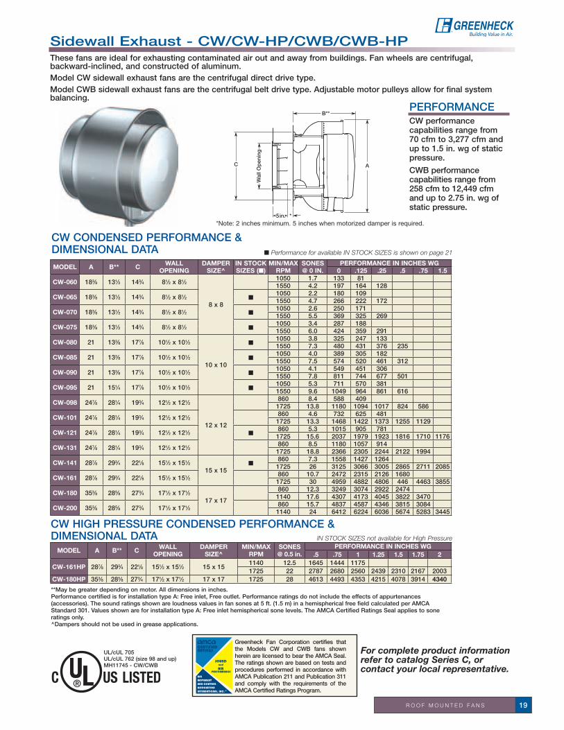
CW CONDENSED PERFORMANCE & DIMENSIONAL DATA n Performance for available in stock sizes is shown on page 21
**May be greater depending on motor. All dimensions in inches.Performance certified is for installation type A: Free inlet, Free outlet. Performance ratings do not include the effects of appurtenances (accessories). The sound ratings shown are loudness values in fan sones at 5 ft. (1.5 m) in a hemispherical free field calculated per AMCA Standard 301. Values shown are for installation type A: Free inlet hemispherical sone levels. The AMCA Certified Ratings Seal applies to sone ratings only.^Dampers should not be used in grease applications.
UL/cUL 705UL/cUL 762 (size 98 and up)MH11745 - CW/CWB
in stock sizes not available for High Pressure
CW HIGH PRESSURE CONDENSED PERFORMANCE & DIMENSIONAL DATA
MODEL A B** C WALL OPENING
DAMPER SIZE^
IN STOCK SIZES (n)
MIN/MAX RPM
SONES @ 0 IN.
PERFORMANCE IN INCHES WG0 .125 .25 .5 .75 1.5
CW-060 183⁄8 131⁄2 143⁄4 81⁄2 x 81⁄2
8 x 8
1050 1.7 133 811550 4.2 197 164 128
CW-065 183⁄8 131⁄2 143⁄4 81⁄2 x 81⁄2 n1050 2.2 180 1091550 4.7 266 222 172
CW-070 183⁄8 131⁄2 143⁄4 81⁄2 x 81⁄2 n1050 2.6 250 1711550 5.5 369 325 269
CW-075 183⁄8 131⁄2 143⁄4 81⁄2 x 81⁄2 n1050 3.4 287 1881550 6.0 424 359 291
CW-080 21 133⁄8 177⁄8 101⁄2 x 101⁄2
10 x 10
n1050 3.8 325 247 1331550 7.3 480 431 376 235
CW-085 21 133⁄8 177⁄8 101⁄2 x 101⁄2 n1050 4.0 389 305 1821550 7.5 574 520 461 312
CW-090 21 133⁄8 177⁄8 101⁄2 x 101⁄2 n1050 4.1 549 451 3061550 7.8 811 744 677 501
CW-095 21 151⁄4 177⁄8 101⁄2 x 101⁄2 n1050 5.3 711 570 3811550 9.6 1049 964 861 616
CW-098 247⁄8 281⁄4 193⁄4 121⁄2 x 121⁄2
12 x 12
860 8.4 588 4091725 13.8 1180 1094 1017 824 586
CW-101 247⁄8 281⁄4 193⁄4 121⁄2 x 121⁄2 860 4.6 732 625 4811725 13.3 1468 1422 1373 1255 1129
CW-121 247⁄8 281⁄4 193⁄4 121⁄2 x 121⁄2 n860 5.3 1015 905 781
1725 15.6 2037 1979 1923 1816 1710 1176
CW-131 247⁄8 281⁄4 193⁄4 121⁄2 x 121⁄2 860 8.5 1180 1057 9141725 18.8 2366 2305 2244 2122 1994
CW-141 287⁄8 293⁄4 221⁄8 151⁄2 x 151⁄215 x 15
n860 7.3 1558 1427 1264
1725 26 3125 3066 3005 2865 2711 2085
CW-161 287⁄8 293⁄4 221⁄8 151⁄2 x 151⁄2 860 10.7 2472 2315 2126 16801725 30 4959 4882 4806 446 4463 3855
CW-180 353⁄8 285⁄8 273⁄4 171⁄2 x 171⁄217 x 17
860 12.3 3249 3074 2922 24741140 17.6 4307 4173 4045 3822 3470
CW-200 353⁄8 285⁄8 273⁄4 171⁄2 x 171⁄2 860 15.7 4837 4587 4346 3815 30841140 24 6412 6224 6036 5674 5283 3445
MODEL A B** C WALLOPENING
DAMPER SIZE^
MIN/MAXRPM
SONES @ 0.5 in.
PERFORMANCE IN INCHES WG.5 .75 1 1.25 1.5 1.75 2
CW-161HP 287⁄8 293⁄4 221⁄8 151⁄2 x 151⁄2 15 x 151140 12.5 1645 1444 11751725 22 2787 2680 2560 2439 2310 2167 2003
CW-180HP 353⁄8 285⁄8 273⁄4 171⁄2 x 171⁄2 17 x 17 1725 28 4613 4493 4353 4215 4078 3914 4340
Sidewall Exhaust - CW/CW-HP/CWB/CWB-HPThese fans are ideal for exhausting contaminated air out and away from buildings. Fan wheels are centrifugal, backward-inclined, and constructed of aluminum.Model CW sidewall exhaust fans are the centrifugal direct drive type. Model CWB sidewall exhaust fans are the centrifugal belt drive type. Adjustable motor pulleys allow for final system balancing.
PERFORMANCECW performance capabilities range from 70 cfm to 3,277 cfm and up to 1.5 in. wg of static pressure.
CWB performance capabilities range from 258 cfm to 12,449 cfm and up to 2.75 in. wg of static pressure.
For complete product information refer to catalog Series C, or contact your local representative.

R O O F M O U N T E D F A N S20
CWB STANDARD PERFORMANCE& DIMENSIONAL DATA n Performance for available in stock sizes is shown on page 21
CWB HIGH PRESSURE PERFORMANCE & DIMENSIONAL DATA in stock sizes not available for High Pressure
**May be greater depending on motor. All dimensions in inches.Performance certified is for installation type A: Free inlet, Free outlet. Power rating (BHP) does not include transmission losses. Performance ratings do not include the effects of appurtenances (accessories). The sound ratings shown are loudness values in fan sones at 5 ft. (1.5 m) in a hemispherical free field calculated per AMCA Standard 301. Values shown are for installation type A: Free inlet hemispherical sone levels. The AMCA Certified Ratings Seal applies to sone ratings only.^Dampers should not be used in grease applications.
SERVICE CHART IN STOCK
NEXT DAY
3 DAY
10 DAY
CW-065 through 121 and 141 ✓ ✓ ✓ ✓
All sizes CW ✓ ✓ ✓
CWB-141 and 180 ✓ ✓ ✓ ✓
All sizes CWB standard and HP ✓ ✓ ✓
MODEL A B** C WALL OPENING
DAMPER SIZE^
IN STOCK SIZES (n)
MIN/MAX RPM
SONES @ 0 IN.
PERFORMANCE IN INCHES WG0 .25 .5 .75 1 2
CWB-098 247⁄8 281⁄4 193⁄4 121⁄2 x 121⁄2
12 x 12
650 8.1 4451725 13.8 1180 1017 824 586
CWB-101 247⁄8 281⁄4 193⁄4 121⁄2 x 121⁄2 860 4.6 732 4811820 14.3 1549 1459 1350 1234 1106
CWB-121 247⁄8 281⁄4 193⁄4 121⁄2 x 121⁄2 685 4.4 8091725 15.6 2037 1923 1816 1710 1571
CWB-131 247⁄8 281⁄4 193⁄4 121⁄2 x 121⁄2 650 6.2 8921645 17.9 2256 2128 2001 1864 1684
CWB-141 287⁄8 293⁄4 221⁄8 151⁄2 x 151⁄215 x 15
n590 5.0 1069
1725 26 3125 3005 2865 2711 2539
CWB-161 287⁄8 293⁄4 221⁄8 151⁄2 x 151⁄2 730 8.1 2098 16691390 22 3996 3806 3584 3340 3078
CWB-180 353⁄8 285⁄8 273⁄4 171⁄2 x 171⁄217 x 17
n630 7.1 2380 1861
1495 28 5648 5443 5254 5082 4921 3564
CWB-200 353⁄8 285⁄8 273⁄4 171⁄2 x 171⁄2 500 6.2 2812 18221210 25 6806 6451 6108 5748 5350
CWB-220 4225⁄32 337⁄8 311⁄4 201⁄2 x 201⁄220 x 20
450 7.3 3585 2624955 25 7607 7202 6799 6347 5844
CWB-240 4225⁄32 337⁄8 311⁄4 201⁄2 x 201⁄2 410 6.4 3717 2471930 24 8431 7985 7536 6953 6375
CWB-300 50 36 383/8 251⁄2 x 251⁄2 25 x 25 355 6.9 5777 4227765 24 12449 11904 11273 10554 9743
MODEL A B** CWALL
OPENINGDAMPER
SIZE^MIN/MAX
RPMSONES @
0.5 IN.PERFORMANCE IN INCHES WG
.5 .75 1.25 1.75 2 2.25 2.75
CWB-101HP 247⁄8 281⁄4 193⁄4 121⁄2 x 121⁄2 12 x 121300 6.0 3352580 16.8 1014 969 861 735 655 550
CWB-141HP 287⁄8 293⁄4 221⁄8 151⁄2 x 151⁄215 x 15
895 6.1 3312110 19.8 1592 1536 1409 1262 1178 1073 804
CWB-161HP 287⁄8 293⁄4 221⁄8 151⁄2 x 151⁄2825 7.0 889
1690 21 2722 2611 2365 2082 1899 1664
CWB-180HP 353⁄8 285⁄8 273⁄4 171⁄2 x 171⁄217 x 17
795 8.3 15701685 27 4495 4369 4085 3768 3575 3325 2766
CWB-200HP 353⁄8 285⁄8 273⁄4 171⁄2 x 171⁄2740 8.1 2024
1400 23 5110 4898 4436 3880 3515
CWB-220HP 4225⁄32 337⁄8 311⁄4 201⁄2 x 201⁄220 x 20
650 8.6 2909 19401085 23 5920 5678 5061 4210 3573
CWB-240HP 4225⁄32 337⁄8 311⁄4 201⁄2 x 201⁄2635 8.1 3046
1070 22 6404 6112 5407 4550 3625
CWB-300HP 50 36 383⁄8 251⁄2 x 251⁄2 25 x 25460 7.3 3125885 23 9014 8603 7678 6353
Sidewall Exhaust - CW/CW-HP/CWB/CWB-HP
•Aluminumhousing•Non-overloadingbackward-inclined
aluminum wheel•Birdscreenmountedtothe
discharge perimeter•Removablemountingplate•Ballbearingmotors•Motorsanddrivesisolatedonshock
mounts
• Adjustablemotorpulley• Adjustablemotorplate• Fanshaftmountedinballbearing
pillow blocks•Static-resistantbelts•Corrosion-resistantfasteners• NEMA-1disconnect
• Aluminumbirdscreen• Gravityandmotorizeddampers(In
stock for CW up to size 240)• Heatbaffles(Beltdrive)• UL/cUL705Electrical• UL/cUL762Grease(Size098andup)• Nonstickwheels(Beltdrive)• Wallgrille• Speedcontrols(Directdrive)• Relubricatablebearings(Beltdrive)• Dualdrives• NEMA-3RandEXPdisconnect
switches• Greenheckcoatings(Seecoatings
page 119)
OPTIONS AND ACCESSORIES
STANDARD CONSTRUCTION FEATURES

R O O F M O U N T E D F A N S 21
CWB PERFORMANCE DATA - IN STOCK stock model cWB fans include birdscreen, disconnect switch, UL/cUL762 and heat baffle.
stock Model cW fans include birdscreen, disconnect switch, UL/cUL 705 label.
MODEL RPM TS SONES @ 0 IN.
MAXBHP
PERFORMANCE IN INCHES WG
0 .125 .25 .375 .5 .625 .75
CW-065-DGEX-QD1/30 HP3 Speed
E 1050 2234 2.2 .009 180 109
G 1300 2765 3.2 .017 223 170 97
D 1550 3297 4.8 .028 266 222 172 95
CW-070-DGEX-QD1/30 HP3 Speed
E 1050 2234 2.5 .008 250 172
G 1300 2765 4.1 .015 309 255 152
D 1550 3297 5.6 .026 369 325 269 160
CW-075-DGEX-QD1/25 HP3 Speed
E 1050 2234 3.3 .012 287 188
G 1300 2765 4.4 .024 356 279 185
D 1550 3297 6.1 .039 424 359 291 204
CW-080-DGEX-QD1/20 HP3 Speed
E 1050 2990 3.8 .016 325 248 133
G 1300 3701 5.4 .031 403 343 272 173
D 1550 4413 7.3 .054 480 431 376 315 236
CW-085-DGEX-QD1/20 HP3 Speed
E 1050 2990 3.6 .018 389 305 182
G 1300 3701 5.4 .035 482 416 340 235
D 1550 4413 7.5 .061 574 520 462 395 313 161
CW-090-DGEX-QD1/15 HP3 Speed
E 1050 2990 3.8 .027 550 450 306
G 1300 3701 5.4 .052 680 600 516 391
D 1550 4413 7.5 .088 811 744 677 603 501 347
CW-095-DGEX-QD1/8 HP
3 Speed
E 1050 2990 4.9 .037 711 569 381
G 1300 3701 7.4 .072 880 773 641 484 200
D 1550 4413 9.6 .121 1049 964 861 746 616 443
CW-121-BX-QD1/6 HP B 1140 3898 7.4 0.14 1346 1260 1179 1091 980 833
CW-141-BX-QD1/4 HP B 1140 4364 11.3 0.29 2064 1972 1864 1744 1604 1429 1166
MODEL HP RPM TS SONES @ 0 IN.
MAX BHP
PERFORMANCE IN INCHES WG
0 .125 .25 .375 .5 .75 1 1.25 1.5 1.75
CWB-141-LMDG-QD590-1590 RPM
1⁄4590 2259 7.3 0.04 1069 851
1090 4173 10.7 0.25 1975 1877 1763 1633 1476
1⁄3 1200 4594 12.1 0.34 2174 2088 1987 1875 1749 1410
1⁄2 1400 5360 15.2 0.53 2537 2465 2382 2292 2196 1974 1675
3⁄4 1590 6087 19.9 0.78 2881 2817 2748 2674 2592 2420 2213 1952
1 1725 6605 26 1.0 3125 3066 3005 2936 2865 2711 2539 2339 2085 1704
CWB-180-LMDG-QD545-1480 RPM
1⁄4 740 3584 9.1 0.25 2795 2596 2422 2115 1723
1⁄3 830 4019 11.4 0.36 3135 2954 2799 2575 2315
1⁄2 960 4649 14.2 0.55 3626 3466 3323 3197 2981 2487
3⁄4 1070 5182 16.4 0.77 4042 3898 3765 3645 3533 3113 2613
1 1200 5811 18.8 1.08 4533 4405 4281 4168 4066 3778 3411 2948
11⁄2 1360 6586 22 1.58 5137 5024 4911 4809 4710 4531 4229 3909
2 1480 7168 26 2.03 5591 5487 5383 5284 5193 5021 4845 4517
CW PERFORMANCE DATA - IN STOCK
Performance certified is for installation type A: Free inlet, Free outlet. Performance ratings do not include the effects of appurtenances (accessories). The sound ratings shown are loudness values in fan sones at 5 ft. (1.5 m) in a hemispherical free field calculated per AMCA Standard 301. Values shown are for installation type A: Free inlet hemispherical sone levels. The AMCA Certified Ratings Seal applies to sone ratings only.
Sidewall Exhaust - CW/CW-HP/CWB/CWB-HP
Performance certified is for installation type A: Free inlet, Free outlet. Power rating (BHP) does not include transmission losses. Performance ratings do not include the effects of appurtenances (accessories). The sound ratings shown are loudness values in fan sones at 5 ft. (1.5 m) in a hemispherical free field calculated per AMCA Standard 301. Values shown are for installation type A: Free inlet hemispherical sone levels. The AMCA Certified Ratings Seal applies to sone ratings only.

R O O F M O U N T E D F A N S22
For complete product information refer to catalog Propeller Upblast Roof Fans - Model RBU, RBUMO, RDU and RGU, or contact your local representative.
Greenheck Fan Corporation certifies that the RBU, RBUMO, and RDU models shown herein are licensed to bear the AMCA seal. The ratings shown are based on tests and procedures performed in accordance with AMCA Publication 211 and AMCA Publication 311 and comply with the requirements of the AMCA Certified Ratings Program.
B
A
CurbCap
C
B
A
CurbCap
C
UL/cUL 705E40001-RBU, RBUMO, RDU
RBU RBUMO
SERVICE CHART 5 DAY
10 DAY
RDU/RBU/RBUMO All Models ✓ ✓
Propeller Upblast Roof Exhaust Fans - RDU/RBU/RBUMOUpblast propeller roof exhaust fans are designed to discharge contaminants up and away from the building for most commercial jobs and many industrial applications. These roof exhaust fans include both belt and direct drive fans with steel or aluminum blades.
Models RBU and RBUMO are belt drive fans that offer the ability to adjust fan speed for system balancing if necessary. These models also offer more flexibility in speeds and motor selections. Model RBU has the motor in the airstream. Model RBUMO has the motor out of the airstream, which allows for high temperature air to be exhausted.
RDU direct drive fans are often preferred for jobs where maintenance access is difficult. Maintenance costs are generally lower with direct drive fans since there are no belts or bearings to replace and no pulleys to adjust.
PERFORMANCERBU and RBUMO performance capabilities range from 3,100 cfm to 64,000 cfm and up to 1 in. wg of static pressure. RDU performance capabilities range from 2,800 cfm to 43,400 cfm and up to 1 in. wg of static pressure.
RDU STANDARD CONSTRUCTION FEATURES• Curb cap, drive frame and windband of
galvanized construction• Galvanized steel windband with built-in
damper stops• Aluminum butterfly dampers• Cast aluminum airfoil blade propeller• Ball bearing motors• Corrosion-resistant fasteners
RBU STANDARD CONSTRUCTION FEATURES• Curb caps and drive frame assemblies of
galvanized steel for sizes 20 to 48, painted steel for sizes 54 and 60
• Galvanized steel windband with built-in damper stops
• Aluminum butterfly dampers• Fabricated steel propeller• Ball bearing motors• Adjustable motor plate• Variable pitch motor pulley• Fan shaft mounted in pillow block bearings
with grease fittings• Static-resistant belts• Corrosion-resistant fasteners
RBUMO STANDARD CONSTRUCTION FEATURES• Fan base, motor cover and windband of galvanized steel• Panel and drive frame assemblies of galvanized steel for sizes
20 to 48, painted steel for sizes 54 and 60• Galvanized steel windband with built-in damper stops• Aluminum butterfly dampers • Fabricated steel propeller • Ball bearing motors • Adjustable motor plate • Variable pitch motor pulley • Relubricatablebearings• Static-resistant belts • Corrosion-resistant fasteners
OPTIONS AND ACCESSORIES• UL/cUL705Electrical• Inletandoutletguards• Extendedlubelines• Greasefittingsforshaftbearings• Bearingswithhightempgrease&fittings• Dualdrives• Belttube• Aluminumpropellers• Galvanizedbutterflydampers• Curbseal• Tie-downpoints• Magneticdamperlatches• Fusiblelinkdamperlifters• Roofcurbsandadaptors• High temperature options (level 2 and 3 - RBUMO)• Greenheckcoatings(Seecoatingspage119)

R O O F M O U N T E D F A N S 23
Please note: Optimum selections shown in bold. All dimensions in inches. *May be greater depending on motor. **RBUMO = 1/2 in. less. Dimension A - given is the inside dimensions of the curb cap. The roof curb should be 11/2 in. less than the curb cap to allow for roofing and flashing. Performance certified is for installation type A: Free inlet, Free outlet. Power rating (BHP/kW) does not include transmission losses. Performance ratings do not include the effects of appurtenances (accessories). The sound ratings shown are loudness values in fan sones at 5 ft. (1.5 m) in a hemispherical free field calculated per AMCA Standard 301. Values shown are for installation type A: Free inlet hemispherical sone levels. The AMCA Certified Ratings Seal applies to sone ratings only.
All dimensions in inches.
RBU STANDARD CONDENSED PERFORMANCE & DIMENSIONAL DATA
RBUMO STANDARD CONDENSED PERFORMANCE & DIMENSIONAL DATA
MODEL A BC
LEVEL CURB CAP
ROOFOPENING LEVEL SONES
@ 0 IN.MAXRPM
PERFORMANCE IN INCHES WG
0 .125 .25 .5 .75 11 & 2 3
RBU-20 271/4 24 15 15 30 24
1L 19.3 1084 5235 46161H 21 1443 4295 4041 36692L 19.3 1084 5235 46162H 21 1443 4295 4041 3669
RBU-24 311/8 26 151/2 163/4 34 28
1L 18.2 808 6791 59851H 28 1351 7382 7037 64912L 22 924 7766 7078 61272H 32 1477 8071 7755 7286 64113L 24 1135 8900 8197 74273H 28 1460 8358 7931 7459 6435 4404
RBU-30 373/8 30 151/2 163/4 40 34
1L 18 695 11108 9534 78451H 27 963 10943 10166 9279 70212L 30 964 15408 14272 131482H 34 1213 13783 13173 12515 11071 93153L 38 1154 17745 16855 158653H 50 1471 16466 15907 15355 14335 13226 11816
RBU-36 431/2 33 163/4 163/4 46 40
1L 20 547 15252 133261H 28 806 16441 15195 138302L 29 689 19212 17866 159172H 41 1014 20683 19637 18743 161453L 61 976 26247 25093 23979 210933H 66 1401 23827 23230 22633 21037 19260 17598
RBU-42 495/6 38 193/8 237/8 52 462L 39 718 32495 30584 28793 23522 141053L 33 652 26765 24942 226913H 57 1011 28701 27743 26759 24540 21672
RBU-48 56 40 193/8 237/8 58 522L 30 594 37987 36154 33838 282403L 45 690 44597 42591 40288 35204 296503H 51 876 40049 38737 37415 34563 31092 27129
RBU-54 625/8 45 191/4 267/8 661/2 602L 30 496 44670 41495 371223L 50 609 56220 53570 50445 42530 271903H 54 811 52094 50598 49059 44746 40046 35353
RBU-60 683/4 48 211/4 27 721/2 66 3L 43 504 64326 61083 561763H 48 673 58475 56434 54119 48865 43082 35057
MODEL A B C CURBCAP
ROOFOPENING LEVEL SONES
@ 0 IN.MAXRPM
PERFORMANCE IN INCHES WG0 .125 .25 .5 .75 1
RBUMO-20 271/4 431/2 193/4 291/2 24
1L 18.3 1060 4797 39791H 19.6 1393 3937 34752L 18.3 1060 4797 39792H 19.6 1393 3937 3475
RBUMO-24 311/8 455/6 171/2 331/2 28
1L 17.7 771 6234 52711H 24 1259 6540 6066 55302L 22 883 7140 6308 53322H 29 1377 7153 6723 6273 50963L 23 1089 7827 7094 62233H 26 1370 7163 6707 6208 4968
RBUMO-30 373/8 513/4 191/2 391/2 34
1L 17.9 673 9706 82021H 26 929 10221 9265 83012L 28 933 13456 12436 112792H 32 1167 12839 12092 11308 96333L 36 1109 15679 14675 136593H 49 1420 15223 14657 14044 12712 11285 9613
RBUMO-36 431/2 55 191/2 451/2 40
1L 19.3 530 14236 124031H 27 784 15501 14137 126772L 28 668 17943 16499 148522H 39 988 19535 18453 17368 149483L 49 943 24356 23220 22077 193343H 61 1343 22439 21888 21337 19655 17885 15850
RBUMO-42 495/6 595/8 195/8 511/2 462L 38 701 29635 28136 26190 21646 156943L 42 750 29671 27925 26138 218243H 53 960 26600 25403 24222 21531 18596 14837
RBUMO-48 56 635/6 213/4 571/2 522L 29 587 34761 32809 30166 240913L 40 676 40135 38262 35865 30524 215183H 47 842 37206 35684 34269 31241 27087 20830
RBUMO-54 625/8 705/8 223/4 66 602H 34 585 38905 36257 331843L 46 591 51679 48380 44763 364363H 50 776 48021 46336 44533 40247 35308
RBUMO-60 683/4 75 23 72 663L 40 493 61784 57265 517783H 46 650 55174 52967 50458 44728 37535 26609
RDU/RBU/RBUMO

R O O F M O U N T E D F A N S24
Nonpowered Gravity Upblast Ventilator - RGUModel RGU is an upblast ventilator designed for use as a weatherproof outlet on vertical high-velocity exhaust systems. They can be furnished without the curb cap for mounting directly on round stacks.
RGU Performance
0.00
0.05
0.10
0.15
0.20
0.25
0.30
0.35
0.40
0.45
0.50
0.55
0.60
0 10,000 20,000 30,000 40,000 50,000 60,000
Volume (cfm)
Sta
tic
Pre
ssur
e D
rop
(in.
wg
)
RGU-18
RGU-20
RGU-24
RGU-30
RGU-36
RGU-42
RGU-48
RGU-54
RGU-60
MINIMUM CFM REQUIRED TO OPEN DAMPERS
CurbCap
A
B
DE
A
C
CurbCap
A
B
DE
A
C
RGU with curb cap
RGU without curb cap
SIZE A B C D E CURB CAP
RECOMMENDED ROOF OPENING
18 25 22 201⁄4 13⁄4 181⁄2 28 2220 271⁄4 24 211⁄4 13⁄4 201⁄2 30 2424 311⁄8 26 24 13⁄4 241⁄2 34 2830 373⁄8 30 263⁄4 13⁄4 305⁄8 40 3436 431⁄2 33 291⁄4 13⁄4 365⁄8 46 4042 487⁄8 38 341⁄4 13⁄4 423⁄4 52 4648 56 40 341⁄4 13⁄4 481⁄2 58 5254 625⁄8 45 401⁄4 13⁄4 55 661⁄2 6060 683⁄4 48 431⁄8 13⁄4 61 721⁄2 66
SERVICE CHART 5 DAY
10 DAY
All Sizes ✓ ✓
SIZEDAMPER
ALUMINUM GALVANIZED18 2750 3520
20 3170 4090
24 3950 5220
30 6050 7130
36 7620 10980
42 11050 13550
48 12820 16420
54 21430 21430
60 24820 24820
For complete product information refer to catalog Propeller Upblast Roof Fans - Model RBU, RBUMO, RDU and RGU, or contact your local representative.
RGU STANDARD CONSTRUCTION FEATURES
• Standard construction is heavy gauge galvanized steel. Nine sizes are available, corresponding to powered units in sizes 18-60.
• Fusiblelinkdamperliftersareavailabletoallow RGU units to function as heat and smoke relief vents.

R O O F M O U N T E D F A N S 25
Greenheck Fan Corporation certifies that the models TAUD and TAUB-CA tube axial fans shown herein are licensed to bear the AMCA Seal. The ratings shown are based on tests and procedures performed in accordance with AMCA Publication 211 and comply with the requirements of the AMCA Certified Ratings Program.
A
21/2 in.
D
B
C
TAUD STANDARD CONDENSED PERFORMANCE & DIMENSIONAL DATA
All dimensions in inches. Performance certified is for installation type A: Free inlet, Free outlet. Performance ratings do not include the effects of appurtenances (accessories).
Greenheck Fan Corporation certifies that the TAUB-L and TAUB-H fans shown herein are licensed to bear the AMCA Seal. The ratings shown are based on tests and procedures performed in accordance with AMCA Publication 211 and AMCA Publication 311 and comply with the requirements of the AMCA Certified Ratings Program.
UL/cUL 705E40001 TAUD/TAUB
MODEL A B C D ROOFOPENING
MIN/MAXRPM
PERFORMANCE IN INCHES WG0 .125 .25 .5 .75 1
TAUD-18 26 46 221/4 251/4 201/2 x 201/2 1140 3221 27391725 4584 4348 4108 3536
TAUD-20 30 461/4 23 27 221/2 x 221/2 1140 4448 39891725 5568 5267 4926 4187
TAUD-24 34 521/4 257/8 307/8 261/2 x 261/2860 5090 4038
1140 7383 6740 60721725 10695 10288 9901 9073 8095 7603
TAUD-30 40 577/8 285/8 371/8 321/2 x 321/2860 10898 9636 82151140 13691 12762 11812 96951725 18144 17485 16789 15137 13450 11405
TAUD-36 46 623/4 31 431/4 381/2 x 381/2860 19008 17401 156041140 22914 21960 20736 18177 149771725 29680 28872 28042 26197 24193 22056
TAUD-42 52 697/8 331/4 495/8 441/2 x 441/2680 21959 19186 15981860 25086 23024 20771 14921
1140 36814 35197 33468 30373 25503
TAUD-48 58 753/8 375/8 553/4 501/2 x 501/2680 30936 27426 23440860 36360 33983 31147 24197
1140 46455 44268 42243 38672 32978 26099
Tube Axial Upblast Roof Exhaust - TAUD/TAUB/TAUB-CAModel TAUD direct drive tube axial upblast roof exhaust fans feature cast aluminum propellers and are designed to efficiently remove and disperse contaminated air. They are best suited for exhausting relatively clean, dry and cool air. Model TAUB belt drive tube axial upblast roof exhaust fans are designed to efficiently remove and disperse contaminated air. The TAUB L/H is available with high temperature options that meet IRI, SBCCI, or can be UL listed as a “Power Ventilator for Smoke Control Systems.”
TUBE AxIAL PERFORMANCETAUD performance capabilities are 2,800 to 46,000 cfm and up to 1 in. wg of static pressure. TAUB-L/H performance capabilities are 5,000 to 60,000 cfm and up to 1 in. wg of static pressure. TAUB-CA performance capabilities are 3,000 to 74,000 cfm and up to 1 in. wg of static pressure.
TAUD TAUB-CA TAUB-L/HSTANDARD
CONSTRUCTION FEATURES
n n nAMCA Certified
performance
n n n Permatector™coating
n nCast aluminum airfoil
propeller
n Fabricated steel propeller
n n Polished steel shaft
n n nHeavy-gauge curb cap,
tubular housing, and windband
n n nSteel or aluminum butterfly backdraft
dampers
n n Adjustable motor plate
n n nCorrosion-resistant
fasteners
n nCast iron pillow block
bearings
n n Extended lube lines
n nMinimum bearing life
L(10) 40,000 hrs
UL Listed “Power Ventilators for Smoke Control Systems” (TAUB-L/H)

R O O F M O U N T E D F A N S26
For complete product information refer to the CAPS program or to catalogs Models TAUD & TAUB-CA and Model TAUB-L/H, or contact your local representative.
TAUB-CA PERFORMANCE & DIMENSIONAL DATA
TAUB-L/H PERFORMANCE & DIMENSIONAL DATAAll dimensions in inches. Greenheck Fan Corporation certifies that the model shown herein is licensed to bear the AMCA Seal. The ratings shown are based on tests and procedures performed in accordance with AMCA Publication 211 and AMCA Publication 311 and comply with the requirements of the AMCA Certified Ratings Program. Performance certified is for installation type A: Free inlet, Free outlet. Power rating (BHP/kW) does not include transmission losses. Performance ratings do not include the effects of appurtenances (accessories). The sound ratings shown are loudness values in fan sones at 5 ft. (1.5 m) in a hemispherical free field calculated per AMCA Standard 301. Values shown are for installation type A: Free inlet hemispherical sone levels. The AMCA Certified Ratings Seal applies to sone ratings only.
All dimensions in inches. Greenheck Fan Corporation certifies that the model shown herein is licensed to bear the AMCA Seal. The ratings shown are based on tests and procedures performed in accordance with AMCA Publication 211 and comply with the requirements of the AMCA Certified Ratings Program. Performance certified is for installation type A: Free inlet, Free outlet. Power rating (BHP/kW) does not include transmission losses. Performance ratings do not include the effects of appurtenances (accessories).
MODEL A B C D ROOFOPENING
MIN/MAX RPM
PERFORMANCE IN INCHES WG0 .125 .25 .5 .75 1.25
TAUB-CA-18 26 46 221/4 251/4 201/2 x 201/2 1400 3288 30792235 4757 4615 4468 4136 3778
TAUB-CA-20 30 461/4 23 27 221/2 x 221/2 1265 3679 33572190 6369 6201 6016 5605 5157
TAUB-CA-24 34 521/4 257/8 307/8 261/2 x 261/2 1015 5241 4695 40591975 10199 9978 9682 9071 8436 6894
TAUB-CA-30 40 577/8 285/8 371/8 321/2 x 321/2 820 7863 6806 55871810 17357 16899 16422 15453 14455 12149
TAUB-CA-36 46 623/4 31 431/4 381/2 x 381/2 745 11254 9741 76581700 25682 25051 24415 23061 21625 17981
TAUB-CA-42 52 697/8 331/4 495/8 441/2 x 441/2 640 13876 116661580 34258 33374 32490 30737 28888 24735
TAUB-CA-48 58 753/8 375/8 553/4 501/2 x 501/2 615 18744 15794 119571550 47242 46125 45008 42744 40285 34427
TAUB-CA-54 64 841/4 411/2 625/8 561/2 x 561/2 585 29622 25840 206691270 64308 62672 61022 57557 53381 43216
TAUB-CA-60 70 903/8 443/4 687/8 621/2 x 621/2 415 32356 27799 22311950 74069 72235 70402 66235 62059 52483
MODEL A B C D MIN/MAXRPM
SONES@ 0 in.
PERFORMANCE IN INCHES WG0 .125 .25 .5 .75 1.25
TAUB-24L 34 521/4 257/8 307/8 830 16.4 5230 43781085 27 6837 6241 5395
TAUB-24H 34 521/4 257/8 307/8 1120 23 5671 5111 45361935 48 9797 9450 9122 8508 7826
TAUB-30L 40 577/8 285/8 371/8 645 15.8 8201 67841090 39 13859 13112 12294
TAUB-30H 40 577/8 285/8 371/8 800 20 7918 6962 57931635 62 16183 15751 15300 14317 13275 10448
TAUB-36L 46 623/4 31 431/4 525 15.2 12232 10170790 27 18406 17050 15725
TAUB-36H 46 623/4 31 431/4 675 21 10993 9732 79981275 59 20765 20131 19479 18046 16295
TAUB-42L 52 697/8 331/4 495/8 460 14.6 17130 14338735 32 27370 25873 24086
TAUB-42H 52 697/8 331/4 495/8 505 17.7 14273 12245 95271030 55 29111 28202 27270 25162 22788
TAUB-48L 58 753/8 375/8 553/4 355 15.2 20588 16454645 37 37407 35386 33209
TAUB-48H 58 753/8 375/8 553/4 450 23 19562 17103 13779905 65 39340 38238 37084 34466 31349
TAUB-54L 64 841/4 411/2 625/8 335 19.3 27859 22275595 53 49480 46830 43652
TAUB-54H 64 841/4 411/2 625/8 400 22 25557 22388 18006845 75 53990 52494 51022 48133 44364 35337
TAUB-60L 70 903/8 443/4 687/8 315 19.7 32133515 47 52534 48397
TAUB-60H 70 903/8 443/4 687/8380 23 31149 27226 21706735 68 60249 57945 56057 52062 47485
• UL/cUL - 705 (Electrical)• Shaft seal (TAUB-CA and TAUB-L/H) • Inlet and outlet guards • Access doors - bolted and hinged• Magnetic damper latches• Fusible link damper lifter• Curb seal• Bearings with high temperature grease and zerk
(TAUB L/H)• Tie-down points• Roof curbs (See page 38-39)
• NEMA-3R disconnect switches• High temperature options (TAUB-L/H) Option I - 200°F (93°C) to 500°F (260°C)
Continuous OperationOption II - 500°F (260°C) for minimum of 4 hoursOption III - 1000°F (538°C) for minimum of 15 minutesOption IV - UL Listed “Power Ventilators for Smoke Control Systems”
• Greenheck coatings (See coatings page 119)
OPTIONS AND ACCESSORIES
Tube Axial Upblast Roof Exhaust - TAUD/TAUB/TAUB-CAModel TAUD direct drive tube axial upblast roof exhaust fans feature cast aluminum propellers and are designed to efficiently remove and disperse contaminated air. They are best suited for exhausting relatively clean, dry and cool air. Model TAUB belt drive tube axial upblast roof exhaust fans are designed to efficiently remove and disperse contaminated air. The TAUB L/H is available with high temperature options that meet IRI, SBCCI, or can be UL Listed as a “Power Ventilator for Smoke Control Systems.”
SERVICE CHART 10 DAY
TAUD/TAUB-CA/TAUB-L/H ✓

R O O F M O U N T E D F A N S 27
Supply Air Fan - SAFThe SAF (Supply Air Fan) is a roof mounted, nontempered, filtered, belt driven make-up air unit. This cost effective forward-curved supply fan performs similar to the RSF and KSFB. Housing is straight sided heavy-gauge galvanized steel.
PERFORMANCEPerformance capabilities range from 725 to 14,000 cfm and up to 3.5 in. wg of static pressure.
SERVICE CHART IN STOCK
10 DAY
SAF-110 through 118 ✓ ✓
SAF-120 ✓
B
A D
C
E
SAF STANDARD CONDENSED PERFORMANCE & DIMENSIONAL DATA n Performance for available in stock sizes is shown on page 28
MODEL A B C D E RECOMMENDED ROOF OPENING
STOCK SIZES (n) CFM PERFORMANCE IN INCHES WG
.125 .25 .5 1 1.5 2.5 3 3.5
SAF-110 30 25 211⁄16 22 11⁄2 161⁄2 x 161⁄2 n
820 432 5491720 688 757 883 1110 13072620 977 1032
SAF-112 34 321⁄16 273⁄8 291⁄4 2 201⁄2 x 201⁄2 n
1250 390 4833000 697 743 843 1026 11793750 849 888 962
SAF-115 34 321⁄16 273⁄8 291⁄4 2 261⁄2 x 261⁄2 n
1300 316 407 5462350 432 498 610 800 952 11394800 780 815
SAF-118 40 361⁄16 311⁄16 32 2 321⁄2 x 321⁄2 n
2500 294 359 4665500 514 550 620 743 851 1042 11348500 760 786 831
SAF-120 46 481⁄16 441⁄16 3513⁄16 21⁄8 381⁄2 x 381⁄24000 275 325 414 5539000 513 538 591 687 772 928 995 1060
14000 772 791
All dimensions in inches. Performance certified is for installation type A: Free inlet, Free outlet. Power rating (BHP) does not include transmission losses. Performance ratings include the effects filters in the airstream.
For complete product information refer to catalog Model SAF, or contact your local representative.
UL/cUL 705E40001 - SAF
Greenheck Fan Corporation certifies that the Model SAF fans shown herein are licensed to bear the AMCA Seal. The ratings shown are based on tests and procedures performed in accordance with AMCA Publication 211 and AMCA Publication 311 and comply with the requirements of the AMCA Certified Ratings Program.

R O O F M O U N T E D F A N S28
Supply Air Fan - SAF
STANDARD CONSTRUCTION FEATURES•Heavy-gaugegalvanizedsteelhousing•Double-width,double-inletforward-curvedwheel•Removablecoverallowscompleteaccessibilitytoblowerassembly•1-inchwashablealuminumfilters,easilyremovableforcleaning•Vibrationisolationforentireblowerassembly•AMCACertifiedRatingsSealforSoundandAirPerformance•MountedandwiredNEMA-1disconnectswitch•Liftinglugs•Energyefficientmotor•UL/cUL705Electrical
OPTIONS AND ACCESSORIES • Ductadaptors(InStock)• Curbadaptors• Gravityandmotorizeddampers(Instock)• High-velocitysupplydampers• Galvanizedroofcurbs(Instock)• Aluminumroofcurbs(Seepages38-39)• Curbextensions• Replacementfiltersets• Curbseal• Curbadapter/reducer
SAF PERFORMANCE DATA - IN STOCK in stock sizes are galvanized steel construction and include washable aluminum filters. UL/cUL 705.
MODEL CFM OV MAXBHP
PERFORMANCE IN INCHES WG
.125 .25 .5 1 1.5 2 2.5 3
SAF-110-LMDX-QD
820 877 0.08 RPM 432 549
1180 1263 0.22 RPM 525 616 780
1540 1658 0.55 RPM 632 707 844 1082
1900 2033 1.02 RPM 745 809 927 1140 1328
2260 2418 1.05 RPM 859 920 1023 1210
2620 2803 0.97 RPM 977 1032
SAF-112-LMDx-QD
1250 1850 0.11 RPM 390 483
1750 2590 0.31 RPM 459 549 682
2250 3330 0.49 RPM 549 615 745
2750 4070 1.04 RPM 647 698 810 990
3250 4810 1.45 RPM 748 790 880 1063
3750 5550 1.5 RPM 849 888 962
SAF-115-LMDx-QD
1300 2717 0.23 RPM 316 407 546
2000 4180 1.05 RPM 387 463 586 781 934
2700 5643 1.89 RPM 479 534 642 821 970 1098
3400 7106 1.91 RPM 577 621 712 870 1011
4100 8569 2.04 RPM 677 717 785 935
4800 10032 1.96 RPM 780 815
SAF-118-LMDx-QD
2500 7400 0.37 RPM 294 359 466
3700 10952 1.67 RPM 376 426 516 664 800
4900 14504 4.46 RPM 466 508 582 713 828 932 1034 1127
6100 18056 4.73 RPM 563 594 661 775 878 973 1059
7300 21608 4.63 RPM 662 688 744 846 939
8500 25160 4.64 RPM 760 786 831
Performance certified is for Model SAF exhaust for installation type A: Free inlet, Free outlet. Power rating (BHP) does not include transmission losses. Performance ratings include the effects of filters in the airstream.The sound ratings shown are loudness values in fan sones at 5 ft. (1.5 m) in a hemispherical free field calculated per AMCA Standard 301. Values shown are for installation type A: Free inlet hemispherical sone levels.
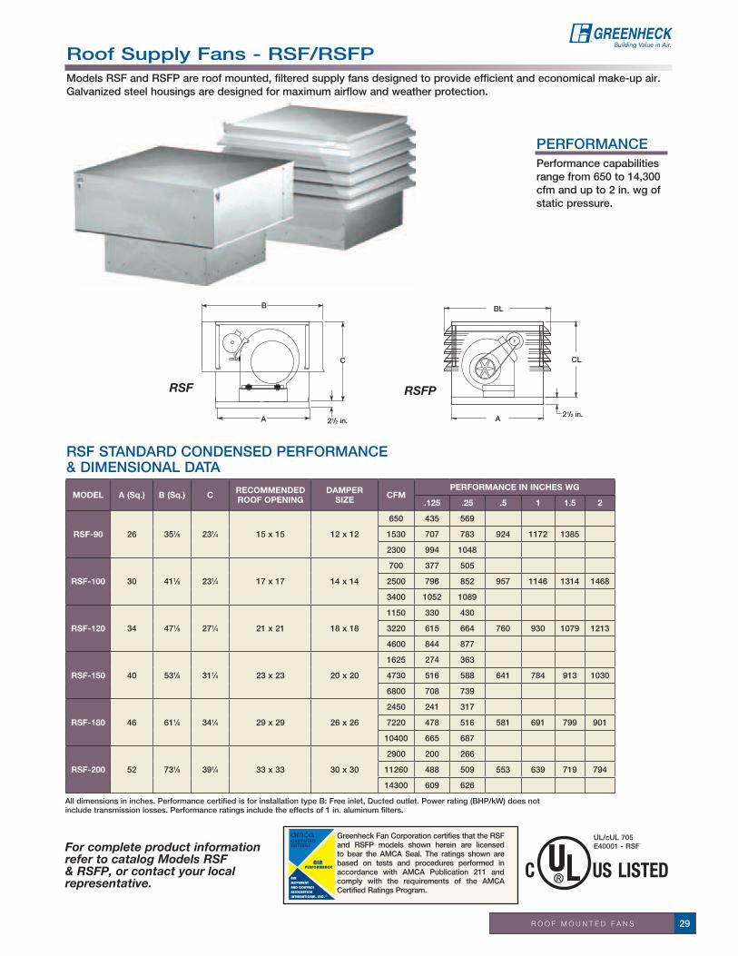
R O O F M O U N T E D F A N S 29
For complete product information refer to catalog Models RSF & RSFP, or contact your local representative.
Greenheck Fan Corporation certifies that the RSF and RSFP models shown herein are licensed to bear the AMCA Seal. The ratings shown are based on tests and procedures performed in accordance with AMCA Publication 211 and comply with the requirements of the AMCA Certified Ratings Program.
RSF STANDARD CONDENSED PERFORMANCE & DIMENSIONAL DATA
B
C
2A 1/2 in.
RSF
BL
CL
2A1/2 in.
RSFP
UL/cUL 705E40001 - RSF
MODEL A (Sq.) B (Sq.) C RECOMMENDED ROOF OPENING
DAMPER SIZE CFM
PERFORMANCE IN INCHES WG
.125 .25 .5 1 1.5 2
RSF-90 26 351⁄8 231⁄4 15 x 15 12 x 12
650 435 569
1530 707 783 924 1172 1385
2300 994 1048
RSF-100 30 411⁄8 231⁄4 17 x 17 14 x 14
700 377 505
2500 796 852 957 1146 1314 1468
3400 1052 1089
RSF-120 34 471⁄8 271⁄4 21 x 21 18 x 18
1150 330 430
3220 615 664 760 930 1079 1213
4600 844 877
RSF-150 40 531⁄8 311⁄4 23 x 23 20 x 20
1625 274 363
4730 516 588 641 784 913 1030
6800 708 739
RSF-180 46 611⁄8 341⁄4 29 x 29 26 x 26
2450 241 317
7220 478 516 581 691 799 901
10400 665 687
RSF-200 52 731⁄8 391⁄4 33 x 33 30 x 30
2900 200 266
11260 488 509 553 639 719 794
14300 609 626
Roof Supply Fans - RSF/RSFPModels RSF and RSFP are roof mounted, filtered supply fans designed to provide efficient and economical make-up air. Galvanized steel housings are designed for maximum airflow and weather protection.
PERFORMANCEPerformance capabilities range from 650 to 14,300 cfm and up to 2 in. wg of static pressure.
All dimensions in inches. Performance certified is for installation type B: Free inlet, Ducted outlet. Power rating (BHP/kW) does not include transmission losses. Performance ratings include the effects of 1 in. aluminum filters.

R O O F M O U N T E D F A N S30
All dimensions in inches. Performance certified is for installation type B: Free inlet, Ducted outlet. Power rating (BHP/kW) does not include transmission losses. Performance ratings include the effects of 1 in. aluminum filters.
RSFP STANDARD CONDENSED PERFORMANCE & DIMENSIONAL DATA
MODEL A (Sq.) BL (Sq.) CLRECOMMENDED ROOF OPENING
DAMPER SIZE
CFMPERFORMANCE IN INCHES WG
.125 .25 .5 1 1.5 2
RSFP-90 26 317⁄8 253⁄8 15 x 15 12 x 12
650 435 569
1530 707 783 924 1172 1385
2300 994 1048
RSFP-100 30 357⁄8 253⁄8 17 x 17 14 x 14
700 377 505
2500 796 852 957 1146 1314 1468
3400 1052 1089
RSFP-120 34 397⁄8 293⁄8 21 x 21 18 x 18
1150 330 430
3220 615 664 760 930 1079 1213
4600 844 877
RSFP-150 40 457⁄8 333⁄8 23 x 23 20 x 20
1625 274 363
4730 516 588 641 784 913 1030
6800 708 739
RSFP-180 46 517⁄8 353⁄8 29 x 29 26 x 26
2450 241 317
7220 478 516 581 691 799 901
10400 665 687
RSFP-200 52 583⁄16 403⁄8 33 x 33 30 x 30
2900 200 266
11260 488 509 553 639 719 794
14300 609 626
Roof Supply Fans - RSF/RSFP
STANDARD CONSTRUCTION FEATURES• Heavy-gaugegalvanizedsteelhousing• Double-width,double-inletforward-curvedwheel• Removable,insulatedcoverwithquickreleaselatches
allows complete accessibility for filters and blower assembly
• Washablealuminumfilters,easilyremovableforcleaning• Vibrationisolationforentireblowerassembly• AMCACertifiedratingssealforairperformance
OPTIONS AND ACCESSORIES • Ductadaptors• Performancebaffle• Gravityandmotorizeddampers• High-velocitysupplydampers• Galvanizedandaluminumroofcurbs(See
pages 38-39)• Aluminumconstruction• 2in.washablealuminumsupplyfilters• Replacementfiltersets• UL/cUL705Electrical• Tie-downpoints• Curbadaptors• Greenheckcoatings(See coatings page 119)
SERVICE CHART 5DAY
10 DAY
RSF/RSFP - All Models and Sizes ✓ ✓

R O O F M O U N T E D F A N S 31
W
B
A sq. 21/2 in.
Tall Base Option
TB
L
A sq.
Tall Base Option
For complete product information refer to catalog Hooded Propeller Roof Fans, or contact your local representative.
OPTIONS AND ACCESSORIES
• Tallbase• Aluminumhousingsand
propellers• Safetyguard• Hoodinsulation• UL/cUL705Electrical• Extendedand1-pointwiring• Aluminum and galvanized roof
curbs• Insectscreenbases• Curbadaptors• Rubbercurbcapstripping• Gravityandmotorizeddampers• Extendedlubricationlines(Belt
Drive)• Relubricatablebearings• Dualdrives• Liftinglugs• Greenheckcoatings(See
coatings page 119)
R/RB STANDARD CONSTRUCTION FEATURES• Motorsareheavy-dutyballbearingtype• Fastenersarecorrosion-resistant• Galvanizedsteelhoodandbasew/galvanizedbirdscreen• Galvanizedsteelwithonepiecedrawnventuri• Level1&2galvanizedandrivetedsteelblades• Level3heavyduty,weldedandreinforcedsteelblades
UL/cUL 705E40001-R
Greenheck Fan Corporation certifies that the R, RC, RB and RBC models shown herein are licensed to bear the AMCA Seal. The ratings shown are based on tests and procedures performed in accordance with AMCA Publication 211 and AMCA Publication 311 and comply with the requirements of the AMCA Certified Ratings Program.
Shown with tall base option.
SERVICE CHART 5 DAY
10 DAY
R/RB/RBC All Models ✓ ✓
Hooded Propeller Roof Fans - Models R/RBHooded propeller roof fans include both belt and direct drive fans with fabricated steel, fabricated aluminum, or cast aluminum blades. A variety of model configurations are available to handle exhaust and supply requirements. Belt drive fans offer the ability to adjust fan speed for system balancing if necessary. Direct drive fans are often preferred for jobs where maintenance access is difficult.
Hooded propeller roof fans can be used for supply or filtered supply with either belt or direct drive units. They can operate from general ventilation up to industrial duty applications with airstream temperatures up to 130°F.
PERFORMANCEPerformance capabilities range from 580 cfm to 86,600 cfm and up to 1.5 in. wg of static pressure.
RB E - 2 L 24 - 7Hooded Roof PropellerBelt DriveRB - Fabricated PropellerRBC - Cast Propeller
(Level 3 only)
Motor HP4=1/4 15=11/2 75=71/23=1/3 20=2 100=105=1/2 30=3 150=157=3/4 50=5 200=2010=1
Fan Size
Propeller TypeL - LowH - High
E - ExhaustS - SupplyF - Filtered Supply
Level ofConstruction1, 2, 3
Belt Drive Model Number CodeBelt Drive Model Number CodeThe model number system is designed to completely identify the fan. The correct code letters must be specified todesignate belt drive with exhaust, supply or filtered supply air configurations. The remainder of the model number isdetermined by the size and performance.

R O O F M O U N T E D F A N S32
RBE STANDARD CONDENSED PERFORMANCE RANGES & DIMENSIONAL DATA
All dimensions in inches. For performance for fan models RBCE, RBCS, RBCF, RBF, RCE3, RCS3, RE2, RS2 refer to catalog Hooded Propeller Roof Fans.*Sones shown apply to the highest cataloged cfm at each fan RPM.Performance certified is for installation type A: Free inlet, Free outlet. Power rating (BHP/kW) does not include transmission losses. Performance ratings include the effects of appurtenances (accessories). The sound ratings shown are loudness values in fan sones at 5 ft. (1.5 m) in a hemispherical free field calculated per AMCA Standard 301. Values shown are for installation type A: Free inlet hemispherical sone levels. The AMCA Certified Ratings Seal applies to sone ratings only.
RBS STANDARD CONDENSED PERFORMANCE RANGES & DIMENSIONAL DATA
MODELA
SQ.B
TALLBASE
TBW x L
ROOFOPENING
SQ.LEVEL
MAXRPM
SONES*PERFORMANCE IN INCHES WG
0 .125 .25 .5 .75 1 1.5
RBE-20 301⁄4 27 441⁄4 54 x 51 221⁄2
1L 1025 16.9 4525 4095 35621H 1348 24 4015 3721 3422 27332L 1171 21 5169 4791 4409 3135 17592H 1550 31 4617 4359 4109 3560 2638
RBE-24 341⁄4 29 461⁄4 66 x 63 261⁄2
1L 809 16.6 6418 5767 48131H 1152 29 5407 5003 44732L 888 19.2 7045 6450 5636 36502H 1311 34 6153 5817 5383 4430 3144 19863L 1278 26 7329 6926 6503 55023H 1461 29 7019 6628 6193 5313 3901 2764
RBE-30 401⁄4 34 511⁄4 75 x 75 321⁄2
1L 696 19.8 9938 8653 67951H 895 23 8717 7899 6992 41762L 864 28 12337 11329 10214 6789 36972H 1125 34 10958 10329 9632 8114 5500 43593L 996 30 11661 10987 10241 8026 5042 34493H 1239 36 12938 12331 11712 10290 8799 7147
RBE-36 461⁄4 391⁄2 563⁄4 88 x 87 381⁄2
1L 551 17.7 13614 11667 94801H 679 19.2 13075 11361 9946 52872L 693 27 17123 15591 13986 10416 51772H 856 34 16484 14985 13893 11342 71333L 922 37 19176 18329 17453 15416 12092 78653H 1357 55 21459 20919 20380 19309 17651 15848
RBE-42 521⁄4 421⁄2 593⁄4 86 x 99 441⁄22H 907 79 28151 26951 25492 22791 200043L 868 39 28038 27046 25859 23097 19272 13887 88373H 898 37 26074 24812 23791 21581 19109 16508 9159
RBE-48 581⁄4 431⁄2 603⁄4 93 x 111 501⁄22H 734 49 32802 31134 28991 25394 20980 167553L 690 32 33135 31527 29743 25451 19395 15045 65253H 842 45 35819 34434 32994 30055 27145 24209 15499
RBE-54 641⁄4 49 661⁄4 112 x 111 561⁄22H 562 72 37837 35477 32810 26992 20503 128783L 650 39 44393 42106 39669 34363 27707 21765 109993H 795 61 45490 43977 42593 39704 36651 32982 24770
RBE-60 701⁄4 50 671⁄4 124 x 123 621⁄22H 559 39 43719 41005 38264 32285 25738 144953L 582 43 56645 53978 50801 43881 36745 27742 169193H 677 49 52948 50706 48472 43809 38757 33604
RBE-72 821⁄2 53 701⁄4 136 x 135 741⁄2 3L 508 52 82283 78328 74199 65283 54396 42796 206433H 606 59 74799 72461 70066 64146 58111 50925 27100
MODEL ASQ. B
TALLBASE
TBW x L
ROOFOPENING
SQ.LEVEL MAX
RPM SONES*PERFORMANCE IN INCHES WG
0 .125 .25 .5 .75 1 1.5
RBS-20 301⁄4 27 441⁄4 54 x 51 221⁄2
1L 1052 22 5329 4701 38681H 1366 26 4325 4043 3684 27722L 1205 27 6104 5571 49762H 1564 34 4952 4712 4404 3732
RBS-24 341⁄4 29 461⁄4 66 x 63 261⁄2
1L 809 18.9 7356 6463 52691H 1157 25 5779 5369 4945 28622L 891 23 8102 7325 6382 28662H 1322 37 6603 6237 5902 4652 2926 20253L 1278 31 8103 7726 7269 56413H 1420 31 7447 7110 6762 5852 4121 2320
RBS-30 401⁄4 34 511⁄4 75 x 75 321⁄2
1L 696 22 10672 9677 77251H 906 29 9271 8573 7808 42892L 869 31 13325 12660 115232H 1136 38 11624 11075 10501 8793 56593L 995 33 12587 12039 11406 8432 47913H 1243 52 13248 12820 12366 11109 8746 6635
RBS-36 461⁄4 391⁄2 563⁄4 88 x 87 381⁄2
1L 551 20 15155 13822 100691H 621 21 13746 12352 92062L 690 33 18978 18190 16276 93512H 783 35 17331 16319 13933 100843L 919 45 20113 19360 18516 152743H 1417 82 21831 21376 20922 19775 18438 16367
RBS-42 521⁄4 421⁄2 593⁄4 86 x 99 441⁄22H 907 75 31192 30325 29365 24974 20586 138563L 870 53 29703 28718 27706 24914 198353H 899 57 28328 27235 26518 24117 19830 15793
RBS-48 581⁄4 431⁄2 603⁄4 93 x 111 501⁄22H 734 43 36484 34764 33369 29323 211213L 689 49 34926 33453 31699 25920 196393H 851 74 38705 37638 36572 34182 29385 25478
RBS-54 641⁄4 49 661⁄4 112 x 111 561⁄22H 562 61 42604 40619 37181 27699 161313L 646 52 46542 44157 41722 34737 26145 197113H 779 81 50138 49057 47590 42687 36984 31629 18704
RBS-60 701⁄4 50 671⁄4 124 x 123 621⁄22H 559 41 45346 42331 39160 30942 218533L 582 54 59743 57010 54205 45052 36007 277243H 695 64 56378 53953 51528 46256 39019 32640
RBS-72 821⁄2 53 701⁄4 136 x 135 741⁄23L 504 55 86595 82944 78711 67046 520573H 620 60 77652 73388 70946 62164 54641 45820
Hooded Propeller Roof Fans - R & RB
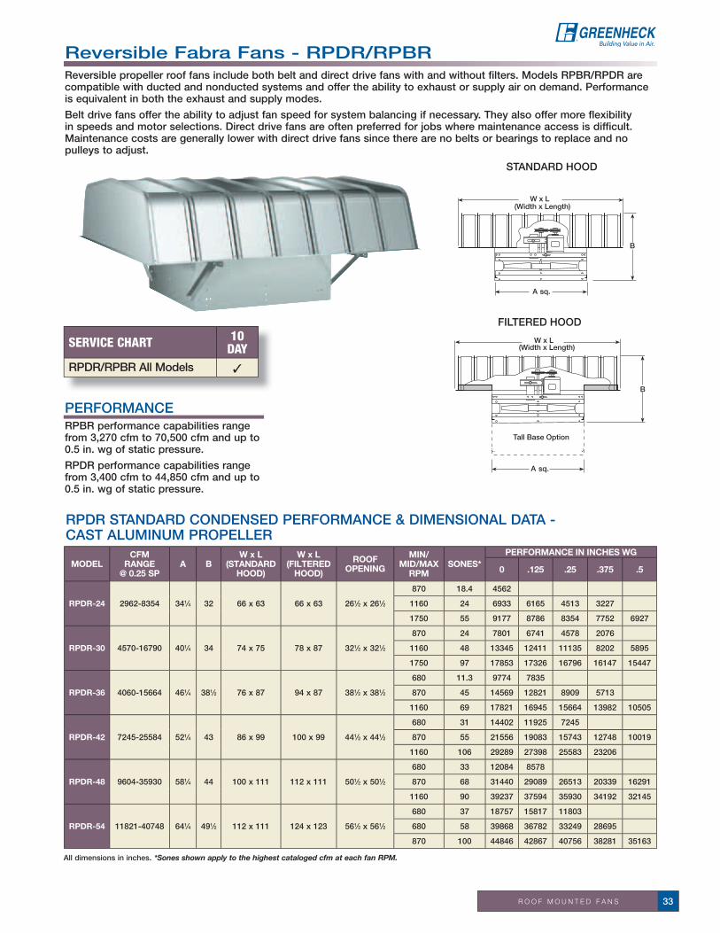
R O O F M O U N T E D F A N S 33
Tall Base Option
B
W x L(Width x Length)
RPBRF(Filtered)
A sq.
B
W x L(Width x Length)
A sq.
RPDR STANDARD CONDENSED PERFORMANCE & DIMENSIONAL DATA - CAST ALUMINUM PROPELLER
All dimensions in inches. *Sones shown apply to the highest cataloged cfm at each fan RPM.
SERVICE CHART 10 DAY
RPDR/RPBR All Models ✓
MODELCFM
RANGE@ 0.25 SP
A BW x L
(STANDARDHOOD)
W x L(FILTERED
HOOD)
ROOFOPENING
MIN/MID/MAX
RPMSONES*
PERFORMANCE IN INCHES WG
0 .125 .25 .375 .5
RPDR-24 2962-8354 341⁄4 32 66 x 63 66 x 63 261⁄2 x 261⁄2
870 18.4 4562
1160 24 6933 6165 4513 3227
1750 55 9177 8786 8354 7752 6927
RPDR-30 4570-16790 401⁄4 34 74 x 75 78 x 87 321⁄2 x 321⁄2
870 24 7801 6741 4578 2076
1160 48 13345 12411 11135 8202 5895
1750 97 17853 17326 16796 16147 15447
RPDR-36 4060-15664 461⁄4 381⁄2 76 x 87 94 x 87 381⁄2 x 381⁄2
680 11.3 9774 7835
870 45 14569 12821 8909 5713
1160 69 17821 16945 15664 13982 10505
RPDR-42 7245-25584 521⁄4 43 86 x 99 100 x 99 441⁄2 x 441⁄2
680 31 14402 11925 7245
870 55 21556 19083 15743 12748 10019
1160 106 29289 27398 25583 23206
RPDR-48 9604-35930 581⁄4 44 100 x 111 112 x 111 501⁄2 x 501⁄2
680 33 12084 8578
870 68 31440 29089 26513 20339 16291
1160 90 39237 37594 35930 34192 32145
RPDR-54 11821-40748 641⁄4 491⁄2 112 x 111 124 x 123 561⁄2 x 561⁄2
680 37 18757 15817 11803
680 58 39868 36782 33249 28695
870 100 44846 42867 40756 38281 35163
Reversible Fabra Fans - RPDR/RPBRReversible propeller roof fans include both belt and direct drive fans with and without filters. Models RPBR/RPDR are compatible with ducted and nonducted systems and offer the ability to exhaust or supply air on demand. Performance is equivalent in both the exhaust and supply modes.
Belt drive fans offer the ability to adjust fan speed for system balancing if necessary. They also offer more flexibility in speeds and motor selections. Direct drive fans are often preferred for jobs where maintenance access is difficult. Maintenance costs are generally lower with direct drive fans since there are no belts or bearings to replace and no pulleys to adjust.
PERFORMANCERPBR performance capabilities range from 3,270 cfm to 70,500 cfm and up to 0.5 in. wg of static pressure.
RPDR performance capabilities range from 3,400 cfm to 44,850 cfm and up to 0.5 in. wg of static pressure.
Tall Base Option
B
W x L(Width x Length)
RPBRF(Filtered)
A sq.
B
W x L(Width x Length)
A sq.
STANDARD HOOD
FILTERED HOOD

R O O F M O U N T E D F A N S34
For complete product information refer to catalog Hooded Propeller Roof Fans, or contact your local representative.
RPBR STANDARD CONDENSED PERFORMANCE & DIMENSIONAL DATA - CAST ALUMINUM PROPELLER
All dimensions in inches. *Sones shown apply to the highest cataloged cfm at each fan RPM.
MODELCFM
RANGE@ 0.25 SP
A BW x L
(STANDARDHOOD)
W x L(FILTERED
HOOD)
ROOFOPENING
MIN/MID/MAX
RPMSONES*
PERFORMANCE IN INCHES WG
0 .125 .25 .375 .5
RPBR-24 2866-7679 341⁄4 32 66 x 63 66 x 63 261⁄2 x 261⁄2
850 24 4457 3269
1295 34 6791 6241 5341 4221
1635 48 8574 8156 7680 6912 6024
RPBR-30 7070-14022 401⁄4 34 74 x 75 78 x 87 321⁄2 x 321⁄2
650 19.5 6943
1000 38 10682 9609 7900
1450 63 15489 14813 14022 13125 11850
RPBR-36 9150-20183 461⁄4 381⁄2 76 x 87 94 x 87 381⁄2 x 381⁄2
625 21 9602 6731
1040 48 15977 14955 13411
1415 83 21739 21021 20183 19081 17888
RPBR-42 8993-25002 521⁄4 43 86 x 99 100 x 99 441⁄2 x 441⁄2
500 20 11888 6714
875 47 20805 18756 15949 11889
1180 75 28057 26551 25002 22725 20603
RPBR-48 7338-32532 581⁄4 44 100 x 111 112 x 111 501⁄2 x 501⁄2
480 22 15117 9863
805 48 25352 23211 20633 15240
1130 86 35587 34108 32532 30814 28809
RPBR-54 12437-41542 641⁄4 491⁄2 112 x 111 124 x 123 561⁄2 x 561⁄2
400 22 21919 16286
645 47 35344 32897 28342 24564 21011
830 73 45482 43760 41542 38359 34546
RPBR-60 14113-43965 701⁄4 501⁄2 124 x 123 136 x 135 621⁄2 x 621⁄2
440 30 26801 20935 14113
630 49 38375 35117 30229 25640 20748
805 79 49034 46569 43965 40611 36072
RPBR-72 22926-63816 801⁄4 53 136 x 135 136 x 147 741⁄2 x 741⁄2
340 24 34031 20400
555 56 55551 51205 44148 28724
705 86 70565 67078 63816 58014 45701
Reversible Fabra Fans - RPDR/RPBR
STANDARD CONSTRUCTION FEATURES• Washablealuminumfilters• Baseandhoodsofgalvanizedsteel• Galvanizedwiremeshbirdscreen• Double-venturi• Reversiblecastaluminumairfoilbladepropeller• Protectiveguards• Ballbearingmotors• Adjustablemotorplate• Adjustablemotorpulley• Fanshaftmountedinballbearingpillowblocks• Static-resistantbelts• Corrosion-resistantfasteners• Tie-downpoints.
(Due to shipping size limitations, hoods for fans sizes 48 and larger will be shipped in sections. Hood assembly requires no special tools or training. Complete illustrated assembly and installation instructions are packed with each fan.)
OPTIONS AND ACCESSORIES• Filteredfanwith2in.filters• Aluminumhousing• Tallbases• Motorizeddampers• Galvanized roof curbs (See pages 38-39)•Aluminumroofcurbs(Seepages38-39)• Insectscreenbases• Rubbercurbcapstripping• Curbadaptors• Extendedlubelines(BeltDrive)• Tie-downpoints• Dualdrives• Hoodinsulation• Greenheckcoatings(Seecoatingspage119)

R O O F M O U N T E D F A N S 35
Propeller Roof Rans - AE/ASModels AE (Axial Exhaust) and AS (Axial Supply) spun aluminum direct drive fans are designed for economy and reliability in low pressure/low volume applications.
PERFORMANCEPerformance capabilities range from 200 cfm to 6,000 cfm and up to 1.0 in. wg of static pressure.
SERVICE CHART NEXT DAY
3 DAY
5 DAY
10 DAY
AE/AS - All Models ✓ ✓ ✓ ✓
STANDARD CONSTRUCTION FEATURES•Aluminumhousingand
propeller•Galvanizedwiremesh
birdscreen•NEMA-1 disconnect•Aluminumcurbcapwith
prepunched holes•Corrosion-resistant
fastners•ODP115Vmotor•UL/cUL705Electrical
MODEL A B C D RECOMMENDED ROOF OPENING HP RPM SONES @
0 IN.PERFORMANCE IN INCHES WG
0 .1 .125 .25 .375 .5 .75 1
AE-10-420-A8 19 245⁄8 151⁄2 51⁄2 141⁄2 x 141⁄2 1⁄8 1750 9.6 550 475 465 347 255 189
AE-12-433-B6 22 285⁄8 161⁄2 61⁄4 141⁄2 x 141⁄2 1⁄6 1140 5.1 1014 853 803 376 144
AE-12-433-A4 22 285⁄8 161⁄2 61⁄4 141⁄2 x 141⁄2 1⁄4 1750 9.0 1556 1460 1437 1291 1055 672 386
AE-14-438-B6 22 285⁄8 161⁄2 61⁄4 161⁄2 x 161⁄2 1⁄6 1140 8.2 1601 1381 1311 925 626 273
AE-14-438-A5 22 285⁄8 161⁄2 61⁄4 161⁄2 x 161⁄2 1⁄2 1750 16.8 2457 2332 2298 2093 1875 1603 1244 716
AE-16-428-B6 26 351⁄4 171⁄4 61⁄4 181⁄2 x 181⁄2 1⁄6 1140 10.5 1999 1817 1764 1418 904 682
AE-16-428-A5 26 351⁄4 171⁄4 61⁄4 181⁄2 x 181⁄2 1⁄2 1750 17.9 3068 2958 2928 2771 2590 2339 1686 1257
AE-18-433-B3 30 351⁄4 171⁄4 61⁄4 201⁄2 x 201⁄2 1⁄3 1140 11.7 2982 2713 2645 2264 1669 1276 499
AE-18-433-A10 30 351⁄4 171⁄4 61⁄4 201⁄2 x 201⁄2 1 1750 28 4578 4395 4349 4141 3908 3660 2935 2327
AE-20-430-B5 34 42 171⁄2 61⁄4 261⁄2 x 261⁄2 1⁄2 1140 11.3 3871 3606 3531 3100 2301 1925
AE-20-430-A15 34 42 171⁄2 61⁄4 261⁄2 x 261⁄2 11⁄2 1750 23 5943 5785 5745 5507 5260 5007 4246 3295
AE-24-422-B5 34 42 171⁄2 61⁄4 261⁄2 x 261⁄2 1⁄2 1140 17.2 5091 4782 4703 4277 3813 3279 2252
AE-24-431-B10 34 42 171⁄2 61⁄4 261⁄2 x 261⁄2 1 1140 19.8 6042 5714 5626 5137 4619 4146 3136 2028
AE STANDARD CONDENSED PERFORMANCE & DIMENSIONAL DATA
MODEL A B C D RECOMMENDED ROOF OPENING HP RPM SONES @
0 IN.PERFORMANCE IN INCHES WG
0 .1 .125 .25 .375 .5 .75 1
AS-10-420-A8 19 245⁄8 151⁄2 51⁄2 141⁄2 x 141⁄2 1⁄8 1750 7.9 503 413 401 343 280 188
AS-12-420-A4 22 285⁄8 161⁄2 61⁄4 141⁄2 x 141⁄2 1⁄4 1750 9.6 929 835 813 595 415
AS-12-433-A4 22 285⁄8 161⁄2 61⁄4 141⁄2 x 141⁄2 1⁄4 1750 11.4 1444 1412 1400 1203 953 641
AS-14-428-A4 22 285⁄8 161⁄2 61⁄4 161⁄2 x 161⁄2 1⁄4 1750 16.1 2041 1940 1912 1742 1567 1380 1018
AS-14-440-A5 22 285⁄8 161⁄2 61⁄4 161⁄2 x 161⁄2 1⁄2 1750 20 2586 2442 2395 2176 1971 1799 1380
AS-16-420-A5 26 351⁄4 171⁄4 61⁄4 181⁄2 x 181⁄2 1⁄2 1750 20 2353 2229 2195 2008 1819 1597 1121
AS-16-428-A7 26 351⁄4 171⁄4 61⁄4 181⁄2 x 181⁄2 3⁄4 1750 21 2920 2826 2802 2602 2376 2188 1693 1200
AS-18-427-A7 30 351⁄4 171⁄4 61⁄4 201⁄2 x 201⁄2 3⁄4 1750 30 3906 3739 3690 3454 3228 2990 2454
AS-18-431-A10 30 351⁄4 171⁄4 61⁄4 201⁄2 x 201⁄2 1 1750 31 4247 4110 4076 3846 3526 3259 2724
AS-20-428-B5 34 42 171⁄2 61⁄4 261⁄2 x 261⁄2 1⁄2 1140 16.7 3488 3202 3125 2715 2315 1847
AS-20-428-A15 34 42 171⁄2 61⁄4 261⁄2 x 261⁄2 11⁄2 1750 29 5355 5181 5137 4886 4648 4408 3830 3272
AS-24-418-B5 34 42 171⁄2 61⁄4 261⁄2 x 261⁄2 1⁄2 1140 24 4569 4289 4215 3841 3392 2958
AS-24-430-B10 34 42 171⁄2 61⁄4 261⁄2 x 261⁄2 1 1140 29 5742 5401 5315 4929 4556 4131 3066
AS STANDARD CONDENSED PERFORMANCE & DIMENSIONAL DATA
Greenheck Fan Corporation certifies that the AE and AS fans shown herein are licensed to bear the AMCA seal. The ratings shown are based on tests and procedures performed in accordance with AMCA Publication 211 and AMCA Publication 311 and comply with the requirements of the AMCA Certified Ratings Program.
For complete product information refer to Propeller Hooded Roof Fans - Series A, or contact your local representative.
UL/cUL 705E40001-AE/AS
Performance certified is for installation type A: Free inlet, Free outlet. Performance ratings include the effects of filters. Speed (RPM) shown is nominal. Performance is based on actual spped of test.
C
B
D
A 1 3/4 in.
OPTIONS AND ACCESSORIES• Galvanizedroofcurbs(InStock)• Aluminumroofcurbs(Seepages38-39)• Gravityandmotorizeddampers(InStock)• Curbextensions• UL/cUL705Electrical• Curbadaptors/reducers• Aluminum wire mesh birdscreen• Speedcontrollers(Instock)• NEMA-3R,NEMA-4andNEMA-4X
disconnect• Greenheckcoatings(Seecoatingspage119)

g R A V i T y V E N T i l A T O R S36
Gravity Ventilators
Spun Aluminum Gravity Ventilators - GRS/GRSFModel GRS is an aluminum ventilator designed for intake (Model GRSI) or relief (Model GRSR) applications with either natural gravity or positive pressure systems. The GRS appearance blends with other Greenheck products and with its low silhouette, avoids the problem of detracting from architectural aesthetics. Exceptional design and construction features make this unit a rugged, efficient, and economical air inlet or outlet. Optional built-in flashing flange (model GRSF) with prepunched holes for quick and easy installations without a roof curb.
All dimensions in inches (millimeters) and the weight in pounds (kilograms). NOTE: Models GRS-8 through GRS-24 have a one-piece cover and shroud. Access is gained through the removal of screws. Models GRS-30 through GRS-48 have a removable cover, separate from the shroud, to facilitate maintenance and servicing of dampers.
GRS DIMENSIONAL DATA n in stock sizes include birdscreen
For complete product information refer to catalog Gravity Ventilators-Model GRS, or contact your local representative.
SERVICE CHART IN STOCK
NEXT DAY
3 & 5 DAY
10 DAY
GRS-8 through 30 ✓ ✓ ✓ ✓
GRS-36 through 48 ✓ ✓ ✓
MODEL A B C D E DIA.THROAT
AREA(FT2)
STOCKSIZES
(n)
CAPACITIES (CFM)
.04 .06 .08 .1 .15 .2 .25 .3 .35
GRS-8 19 201⁄2 71⁄4 11⁄2 201⁄4 81⁄4 0.37 nRELIEF 231 282 326 365 446 516 576 631 682INTAKE 178 218 252 282 345 398 445 488 527
GRS-10 19 201⁄2 73⁄4 2 201⁄4 101⁄4 0.57 nRELIEF 331 406 468 524 641 741 828 907 980INTAKE 279 342 395 442 541 624 698 765 826
GRS-12 22 29 10 31⁄2 231⁄4 121⁄4 0.82 nRELIEF 468 573 662 740 907 1047 1171 1282 1385INTAKE 400 490 566 633 775 895 1001 1097 1184
GRS-15 22 29 10 31⁄2 231⁄4 141⁄4 1.12 nRELIEF 663 811 937 1048 1283 1481 1656 1814 1960INTAKE 553 677 782 874 1071 1237 1383 1515 1636
GRS-16 26 29 11 41⁄4 271⁄4 161⁄4 1.45 nRELIEF 870 1065 1230 1375 1685 1945 2175 2382 2573INTAKE 742 908 1049 1173 1436 1658 1854 2031 2194
GRS-18 30 351⁄2 93⁄4 13⁄4 311⁄4 201⁄4 1.83 nRELIEF 1060 1298 1499 1676 2052 2370 2649 2902 3135INTAKE 901 1104 1274 1425 1745 2015 2253 2468 2665
GRS-20 30 351⁄2 111⁄4 33⁄4 311⁄4 201⁄4 2.25 nRELIEF 1284 1572 1815 2029 2486 2870 3209 3515 3797INTAKE 1096 1343 1550 1733 2123 2452 2741 3002 3243
GRS-24 34 381⁄4 11 4 351⁄4 241⁄2 3.24 nRELIEF 1879 2301 2657 2971 3638 4201 4697 5145 5558INTAKE 1542 1888 2180 2438 2985 3447 3854 4222 4560
GRS-30 40 48 183⁄4 57⁄16 — 301⁄2 5.032 nRELIEF 2281 2794 3226 3607 4418 5101 5703 6247 6748INTAKE 2013 2465 2847 3183 3898 4501 5032 5512 5954
GRS-36 46 563⁄4 211⁄4 6 — 361⁄2 7.291RELIEF 3279 4016 4637 5184 6349 7331 8197 8979 9699INTAKE 2921 3577 4130 4618 5656 6531 7301 7998 8639
GRS-42 52 631⁄4 241⁄4 61⁄4 — 421⁄2 9.765RELIEF 4672 5722 6607 7387 9047 10447 11680 12795 13820INTAKE 3911 4791 5532 6185 7574 8746 9779 10712 11570
GRS-48 58 72 261⁄4 61⁄2 — 481⁄2 12.83RELIEF 6211 7607 8783 9820 12027 13888 15527 17009 18372INTAKE 5139 6294 7268 8126 9952 11491 12848 14074 15201
STANDARD CONSTRUCTION FEATURES• Aluminum housing• Aluminum curb cap with prepunched
mounting holes• Recommended roof opening dimension is
at least 2.5 in. larger than the damper size
OPTIONS AND ACCESSORIES• Gravityandmotorizeddampers(Instock)• Galvanizedroofcurbs(InStock)• Aluminumroofcurbs(Seepages38-39)• Extendedbases• Rubbercurbcapstripping• Aluminumcurbadaptors• Hoodinsulation(1/2in.and1in.)• Insectscreeninframe• Greenheckcoatings(See coatings page 119)
B
A
D
1¾ (44)
C
Dia.
GRS - Sizes 30 thru 48GRS - Sizes 8 thru 24
A
D
1¾ (44)
C
Dia.
B
B
DC
GRS with Optional Flashing Flange (Model GRSF) - Sizes 8 thru 24
EDia.

g R A V i T y V E N T i l A T O R S 37
Fabrahoods - Gravity Intake/Relief - FGI/FGRThe low silhouette Fabrahoods are designed for intake (Model FGI) or relief (Model FGR) applications with either natural gravity or positive pressure systems. In appearance, load bearing strength, weather resistance and dimensional flexibility, the Fabrahood design is superior. The selections in this area are based on nonducted applications.
STANDARD CONSTRUCTION FEATURES• Precision formed locked rib construction• Available in aluminum or galvanized steel construction• 0.5 in. galvanized steel mesh birdscreens• Heavy-gauge galvanized steel support members• Tie-down points• Units with a throat size exceeding 60 in. x 120 in. will have
12 in. galvanized bases as standard• Recommended roof opening dimension is at least 2.5 in.
larger than the damper size
For complete product information refer to catalog Gravity Ventilatiors-Models FGI & FGR, or contact your local representative.
FABRAHOOD - GRAVITy - INTAKE PERFORMANCE DATA (Per Square Foot Of Throat Area)
SERVICE CHART 5 DAY
10 DAY
Fabrahood Intake and ReliefSizes - 8 in. x 8 in. - 72 in. x 180 in. ✓ ✓
INTAKE STATIC PRESSURE DROP
DUCTED .03 .047 .071 .089 .119 .149
NONDUCTED .053 .085 .127 .158 .212 .267
HOOD INTAKE VELOCITY 235 297 364 406 470 527
THROAT VELOCITY 475 600 735 820 950 1065
FABRAHOOD - GRAVITy - RELIEF PERFORMANCE DATA (Per Square Foot Of Throat Area)
RELIEF STATIC PRESSURE DROP
DUCTED .024 .043 .06 .084 .107 .136
NONDUCTED .042 .075 .105 .146 .186 .236
HOOD/THROAT VELOCITY 420 560 660 780 880 990
OPTIONS AND ACCESSORIES• 12in.highbase• Aluminumorgalvanizedroofcurbs• Gravityandmotorizeddampers• Aluminumbirdscreenorinsectscreen• Fiberglassinsulation(1/2 in. or 1 in.)• 2in.washablealuminumsupplyfilters(10dayonly)• Greenheckcoatings(Seecoatingspage119)

R O O F C U R b S38
Roof Curbs & ExtensionsGreenheck roof curbs, extended bases, sound curbs, equipment supports, bases and adaptors are available from both stock and Quick Build programs in a variety of styles and materials.
For complete product information refer to our Roof Curbs, Extensions and Equipment Supports catalog, or contact your local representative.
•DamperTrays•Insulation(AllexceptGPE,VCEandGPFV)•StepforInsulation(GPRonly-upto6in.)
•Double-ShellConstruction(AllexceptATandGPE)•Single-Pitch(GPI,GPFandATS)•RidgeMount(GPI,GPFandATS)
For complete product information
ROOF TYPE/APPLICATION DESCRIPTION MODEL & SERVICE
CHARTIN
STOCKNEXT DAY
3 & 5 DAY
10 DAY
Flat, insulated or non-
insulated roof decks Welded, straight
sided construction with rigid fiberglass insulation and 2 in.
mounting flange
GPI - Galvanized 12 in. high, with or without damper tray, square sizes for stock fans
✓ ✓ ✓ ✓
Flat, pitched or ridged,
insulated or non-insulated
roof decks
GPI - Aluminum or galvanized,
other heights, non-stock square and rectangular sizes
✓* *18 in. high galvanized
GPI curbs are available from
Miami, FL stock
✓ ✓ ✓
Flat, non-insulated roof
decks
Welded, canted construction with
rigid fiberglass insulation
GPS - All types, sized to meet your
requirements✓ ✓ ✓
Flat, pitched or ridged, non-insulated roof
decks
Welded, straight sided construction with rigid fiberglass insulation and 5 in.
mounting flange
GPF - All types, sized to meet your
requirements✓ ✓ ✓
Flat, insulated roof decks
Welded, raised cant construction
with rigid fiberglass insulation
GPR - All types, sized to meet your
requirements✓ ✓ ✓
Adaptors/Reducers
Used to match new fans to existing
roof curbs. Welded galvanized steel or
aluminum.
Curb Adaptors and Reducers ✓ ✓ ✓
OPTIONS AND ACCESSORIES
Roof Curbs

R O O F C U R b S 39
ROOF TYPE/APPLICATION DESCRIPTION MODEL &
SERVICE CHARTIN
STOCKNEXT DAY
3 & 5 DAY
10 DAY
Flat roof decks in kitchen
applications
Welded, vented straight sided curb
designed for use with the Greenheck Model CUBE fan to provide the 40 in. minimum discharge height
above the roof line (per NFPA 96)
GPFV - Galvanized,
square sizes for stock fans
✓ ✓ ✓ ✓
Flat roof decks in kitchen
applications
GPFV - Aluminum or galvanized, other heights,
nonstock square sizes
✓*Wisconsin
only✓ ✓ ✓
Curb extensions in kitchen systems
Welded, vented curb extension designed for use with an 8 in. high roof curb and
the Greenheck Model CUBE fan to provide the 40 in. minimum discharge height
above the roof line (per NFPA 96)
VCE - Galvanized, square sizes for
stock fans✓ ✓ ✓ ✓
Curb extensions in kitchen systems
VCE - Aluminum or galvanized, other heights,
nonstock square sizes
✓ ✓ ✓
Curb extensions
Welded, with access door for easy access to the damper and damper actuator
as well as fulfilling additional height
requirements
GPE/GPEx ✓ ✓ ✓
Equipment supports
Welded aluminum or galvanized canted
construction
GESS/GESR/ES Equipment supports
✓ ✓ ✓
Insulated and non-insulated flat roof decks, pitched roofs,
curb extensions
Welded aluminum or galvanized canted
construction for curbs, straight sided for
extensions with rigid fiberglass insulation
ATS/ATR/ATE/ATI Sound
attenuating curbs✓
Flat, non-insulated
roof decks for high-wind and hurricane
zones
Welded straight-sided, insulated, 5 in.
fl ashing fl angeH-GPF ✓ ✓ ✓
Flat, non-insulated
roof decks for high-wind and hurricane
zones
Welded straight-sided, insulated, 5 in. fl ashing fl ange with
12 gauge steel
SD-Curb ✓
Specifi cally for Lab Exhaust
Fans
Welded, straight sided, insulated, 5 in.
fl ashing fl angeGPE-LE ✓
Roof Curbs & Extensions

C E i l i N g , C A b i N E T A N D i N l i N E F A N S40
SP-A SP-B
SERVICE CHART IN STOCK
3 DAY
10 DAY
Standard Construction ✓ ✓ ✓
Speed Control, Mounted & Wired
✓ ✓
Light, SP-A50, 70, 90, 110, 125 SP-B50, 80, 150
✓ ✓
Light, SP-B70, 90, 110 ✓ ✓
Fan/CRD UL Listed Assembly ✓ ✓
277 volt SP-A 110, 125, 190 ✓ ✓
277 volt SP-B 110, 150, 200 ✓ ✓
Contractor 4-Packs ✓ ✓
Contractor Packs-Housings (sizes B70-B110) - Miami
✓ ✓ ✓
Motion Sensor - Grille Mounted ✓
SP FANSSTANDARD FEATURES
A B C
✓ ✓ ✓Backdraft Damper - Prevents unwanted backdrafts.
✓Spring Loaded Aluminum Backdraft Damper - Eliminates rattling or unwanted backdrafts (sizes 110 and up).
✓Outlet - Both square and round outlets are fi eld rotatable from horizontal to vertical discharge.
✓ ✓ ✓Round Outlet (4 or 6 in.) - up to size A90. Versatile for quick, easy connections.
✓ ✓Power Assembly - Removes quickly for maintenance.
✓External Electrical Access - Eliminates removing motor pack, saving installation time.
✓ ✓ Electrical Knockout - Eliminates drilling holes.
✓ ✓ ✓Disconnect (Plug Type) - Servicing is quick and safe.
✓ ✓Electrical Junction Box - Large for easy wiring.
✓ ✓Attractive Designer Grille - Concealed attachment screws securely to fasten grille to housing for quiet, rattle free operation.
✓ ✓ ✓Mounting Brackets - Fully adjustable for multiple installation types.
✓ ✓Housing - Embossed galvanized steel for rigidity and low-profi le for height restricted areas.
✓ ✓ ✓
PSC Compatible Motors - 50 cycle, 220v, and 240v options. 60 cycle, 115v, 208v, 220v, 230v, and 277v options. (Check factory for availability)
✓ ✓ ✓ 3 year Warranty
✓ ✓ ✓UL listed for above showers w/ GFCI branch protected circuit
OPTIONS AND ACCESSORIES •Grilles•Lights•Ceilingradiationdampers(CRD)•Vibrationisolationkits•Speedcontrols•Motiondetectors•Timedelays•Roofdischargeaccessories•Walldischargeaccessories•Transitions•Filters•Contractorpaksnote: see pages 44-47 for full stock accessory listing
PERFORMANCEModels SP-A, SP-B, and SP-C are compact exhaust fans with performance capabilities of 29 cfm to 1600 cfm and up to 1 in. wg.
Ceiling Exhaust - SPModel SP ceiling exhaust fans are designed for clean air applications where low sound levels are desired. Low sound levels are achieved through quiet running forward-curved wheels.
SP-C
Inline, Ceiling andSidewall Exhaust

C E i l i N g , C A b i N E T A N D i N l i N E F A N S 41
C
D
B A
E
B A
C D
BA
C D
E
E
C
B A
DE
All dimensions in inches. Grille dimensions are for the designer grille except on model SP-C50 where the dimensions are shown for the decorative grille.Performance certified is for installation type B: Free inlet, Ducted outlet. Performance ratings include the effects of an inlet grille and backdraft damper. Speed (RPM) shown is nominal. Performance is based on actual speed of test. The sound ratings shown are loudness values in fan sones at 5 ft. (1.5 m) in a hemispherical free field calculated per AMCA Standard 301. Values are for installation type B: free inlet sone levels. The AMCA Certified Ratings Sound Seal applies to sone ratings only.
For complete product information refer to catalog
Models SP and CSP, or contact your local representative.
SP PERFORMANCE & DIMENSIONAL DATA - IN STOCK
UL/cUL 507E33599 Ceiling Exhaust Fans are also UL Listed for sizes 50 through 390 for above bathtub/shower with GFCI branch protected circuit. File No. E33599
MODEL A B COUTLET
RPM AMPS WATTS SONES @ 0 IN. GRILLE SIZE
PERFORMANCE IN INCHES WGD E 0.00 .100 .125 .250 .375 .500 .625 .750 1.00
SP-C50-QD 71⁄2 71⁄2 35⁄8 3 dia. x 15⁄8 1680 0.80 46 2.9 91⁄4 x 9 52 49 48 47 44 38 29
SP-B50-QD 137⁄8 111⁄2 615⁄16 4 dia. x 3⁄4 625 0.50 38 1.7 147⁄8 x 131⁄4 67 54 51 41 30
SP-B70-QD 137⁄8 111⁄2 615⁄16 4 dia. x 3⁄4 675 0.53 45 1.7 147⁄8 x 131⁄4 77 71 68 57 50 40
SP-B80-QD 137⁄8 111⁄2 615⁄16 4 dia. x 3⁄4 900 0.60 54 2.9 147⁄8 x 131⁄4 87 80 78 69 61 54 44 30
SP-B90-QD 137⁄8 111⁄2 715⁄16 6 dia. x 11⁄4 700 0.65 50 1.9 147⁄8 x 131⁄4 102 93 89 75 59 45 30
SP-B110-QD 137⁄8 111⁄2 715⁄16 6 dia. x 11⁄4 950 1.14 80 2.0 147⁄8 x 131⁄4 133 114 111 98 96 94 92 85 51
SP-B150-QD 137⁄8 111⁄2 715⁄16 6 dia. x 11⁄4 1050 1.70 129 3.0 147⁄8 x 131⁄4 160 156 156 154 152 150 147 139 92
SP-B200-QD 137⁄8 111⁄2 715⁄16 6 dia. x 11⁄4 1100 2.20 173 4.4 147⁄8 x 131⁄4 197 195 195 191 188 184 181 166 128
SP-A50-QD 131⁄4 105⁄8 115⁄8 6 6 700 0.31 18 0.7 147⁄8 x 131⁄4 76 51 48 30
SP-A70-QD 131⁄4 105⁄8 115⁄8 6 6 850 0.27 20 1.1 147⁄8 x 131⁄4 83 70 67 42
SP-A90-QD 131⁄4 105⁄8 115⁄8 6 6 900 0.34 29 1.1 147⁄8 x 131⁄4 99 88 85 62 25
SP-A110-QD 131⁄4 105⁄8 101⁄2 8 6 950 0.58 49 1.3 147⁄8 x 131⁄4 119 110 106 89
SP-A125-QD 131⁄4 105⁄8 101⁄2 8 6 1100 0.62 53 1.4 147⁄8 x 131⁄4 135 123 121 105
SP-A190-QD 131⁄4 105⁄8 101⁄2 8 6 1400 1.30 113 3.2 147⁄8 x 131⁄4 216 197 192 167 134
SP-A200-QD 14 117⁄8 111⁄4 8 8 900 0.43 48 2.0 147⁄8 x 131⁄4 247 226 220 197 172 142 105 68
SP-A250-QD 14 117⁄8 111⁄4 8 8 1000 0.77 83 2.9 147⁄8 x 131⁄4 272 252 246 228 211 186 158 119
SP-A290-QD 14 117⁄8 111⁄4 8 8 1050 0.72 81 3.2 147⁄8 x 131⁄4 315 293 287 258 232 207 176 125
SP-A390-QD 14 117⁄8 111⁄4 8 8 1350 1.34 135 5.4 147⁄8 x 131⁄4 410 395 392 369 345 325 308 280
SP-A410-QD 18 143⁄8 141⁄2 8 8 1000 1.74 121 4.1 193⁄8 x 163⁄8 443 413 405 351 306
SP-A510-QD 18 143⁄8 141⁄2 8 8 1070 3.30 224 6.0 193⁄8 x 163⁄8 557 512 501 439 392 325
SP-A700-QD 235⁄8 115⁄8 115⁄8 191⁄2 8 1100 3.20 350 6.1 251⁄8 x 131⁄2 757 730 723 700 680 650 613 560 397
SP-A710-QD 18 143⁄8 141⁄2 10 8 1080 4.40 285 7.4 193⁄8 x 163⁄8 752 714 701 653 588 486 320
SP-A780-QD 18 143⁄8 141⁄2 10 8 1600 3.30 348 10.2 193⁄8 x 163⁄8 812 783 776 741 704 665 625 582
SP-A900-QD 233⁄4 143⁄8 141⁄2 183⁄4 8 950 4.00 285 5.2 25 x 163⁄8 955 907 897 842 774 701
SP-A1050-QD 233⁄4 143⁄8 141⁄2 183⁄4 8 1095 6.30 420 7.2 25 x 163⁄8 1125 1059 1043 964 886 797 663
SP-A1410-QD 233⁄4 143⁄8 141⁄2 183⁄4 8 1450 7.40 786 11.6 25 x 163⁄8 1455 1415 1404 1354 1308 1263 1219 1174
SP-A1550-QD 233⁄4 143⁄8 141⁄2 183⁄4 8 1610 8.60 818 12.4 25 x 163⁄8 1607 1568 1558 1507 1449 1408 1369 1323
Ceiling Exhaust - SP
C
D
B A
E
B A
C D
BA
C D
E
E
C
B A
DE C
D
B A
E
B A
C D
BA
C D
E
E
C
B A
DE
C
D
B A
E
B A
C D
BA
C D
E
E
C
B A
DE
SP-C50 SP-A110 through SP-A510 and SP-A710 & SP-A780
SP-B50 through SP-B200 SP-A700, SP-A900 & SP-A1550
Greenheck Fan Corporation certifies that the SP models shown herein are licensed to bear the AMCA seal. The ratings shown are based on tests and procedures performed in accordance with AMCA Publication 211 and AMCA Publication 311 and comply with the requirements of the AMCA Certified Ratings Program.

C E i l i N g , C A b i N E T A N D i N l i N E F A N S42
C
AB
Ddia.
InletF x G
B A
C
DE
F
G
CSP-B
CSP-A
SERVICE CHART IN STOCK
3 DAY
10 DAY
CSP-B110 through -A1550 - 115 Volt Mtr Construction
✓ ✓ ✓
CSP-A1750 through -A3600 ✓ ✓
CSP-B110 through -A190 with 277 Volt Motor
✓ ✓
CSP FANSSTANDARD FEATURES
A B
✓ ✓Aluminum Backdraft Damper - Prevents unwanted backdrafts.
✓Spring Loaded Aluminum Backdraft Damper - Eliminates rattling or unwanted backdrafts.
✓ ✓Power Assembly - Removes quickly and is rotatable from horizontal to vertical discharge.
✓ ✓External Electrical Access - Eliminates removing motor pack, saving installation time.
✓ ✓Access Panel - Gain easy access to internal components once installed.
✓ ✓Mounting Brackets - Fully adjustable for multiple installation types.
✓ ✓ Compatible with Speed Controllers
✓ ✓ 3 year Warranty
✓ ✓UL listed for above showers w/ GFCI branch protected circuit.
Inline Cabinet Exhaust - CSPModel CSP inline cabinet fans are designed for clean air applications where low sound levels are desired. Low sound levels are achieved through quiet running forward-curved wheels.
PERFORMANCEModels CSP-B110 through A3600 are duct mounted with performance capabilities of 77 cfm to 3,778 cfm and up to 1 in. wg of static pressure.
A
C
B
CSP-A - DOUBLE-SCROLL
OPTIONS AND ACCESSORIES •Vibrationisolationkits•Speedcontrols•Motiondetectors•Timedelays•Roofdischargeaccessories•Walldischargeaccessories•Transitionsnote: see pages 44-47 for full stock accessory
listing

C E i l i N g , C A b i N E T A N D i N l i N E F A N S 43
Greenheck Fan Corporation certifies that the CSP models shown herein are licensed to bear the AMCA Seal. The ratings shown are based on tests and procedures performed in accordance with AMCA Publication 211 and comply with the requirements of the AMCA Certified Ratings Program.
For complete product information refer to catalog
Models SP and CSP, or contact your local representative.
CSP PERFORMANCE AND DIMENSIONAL DATA
UL/cUL 507E33599 Cabinet Fans are also UL Listed for above bathtub/shower with GFCI branch protected circuit. File No. E33599
Inline Cabinet Exhaust - CSP
MODEL A B C D E F G RPM AMPS WATTS WT PERFORMANCE IN INCHES WG0 .125 .25 .375 .5 .75 1
CSP-B110 137⁄8 111⁄2 715⁄16 6 11⁄4 101⁄4 31⁄4 950 1.14 80 101/4CFM 103 100 98 97 96 86
Sones 2.0 2.1 2.3 2.6 2.7 3.3
CSP-B150 137⁄8 111⁄2 715⁄16 6 11⁄4 101⁄4 31⁄4 1050 1.70 129 101/4CFM 151 150 148 148 146 135
Sones 2.5 2.7 2.9 3.0 3.4 3.9
CSP-B200 137⁄8 111⁄2 715⁄16 6 11⁄4 101⁄4 31⁄4 1100 2.20 173 101/4CFM 186 184 182 182 179 170
Sones 3.4 3.6 4.0 4.0 4.1 4.5
CSP-A110 131⁄4 105⁄8 101⁄2 8 6 12 91⁄4 950 0.62 51 16CFM 124 111 102 77
Sones 1.1 1.1 1.3 1.3
CSP-A125 131⁄4 105⁄8 101⁄2 8 6 12 91⁄4 1100 0.63 55 16CFM 138 124 114 91
Sones 1.4 1.3 1.4 1.7
CSP-A190 131⁄4 105⁄8 101⁄2 8 6 12 91⁄4 1400 1.10 100 16CFM 215 198 180 160 122
Sones 2.3 2.2 2.7 2.9 3.0
CSP-A200 14 117⁄8 111⁄4 8 8 127⁄8 10 900 0.43 48 23CFM 254 226 203 178 145 70
Sones 0.8 0.8 1.3 1.5 1.9 2.1
CSP-A250 14 117⁄8 111⁄4 8 8 127⁄8 10 1000 0.79 83 23CFM 266 242 222 206 188 133
Sones 1.3 1.5 2.3 3.3 3.4 3.0
CSP-A290 14 117⁄8 111⁄4 8 8 127⁄8 10 1050 0.71 80 23CFM 318 293 266 248 230 145
Sones 1.6 1.8 2.6 3.3 4.0 3.4
CSP-A390 14 117⁄8 111⁄4 8 8 127⁄8 10 1350 1.33 144 23CFM 412 398 383 363 340 309
Sones 2.8 2.8 3.2 3.7 4.7 6.5
CSP-A410 18 143⁄8 141⁄2 8 8 167⁄8 131⁄4 1000 1.87 139 36CFM 447 403 364 317 217
Sones 2.2 2.2 2.5 2.7 2.7
CSP-A510 18 143⁄8 141⁄2 8 8 167⁄8 131⁄4 1070 3.11 217 36CFM 545 507 464 406 325
Sones 3.1 2.8 2.8 2.7 3.1
CSP-A700 235⁄8 115⁄8 115⁄8 191⁄2 8 225⁄8 101⁄2 1100 3.20 350 34CFM 766 753 740 726 703 636 419
Sones 2.6 2.4 2.4 2.5 2.6 3.0 4.9
CSP-A710 18 143⁄8 141⁄2 10 8 167⁄8 131⁄4 1080 4.40 325 36CFM 737 688 635 567 475
Sones 3.2 3.2 3.3 2.7 2.5
CSP-A780 18 143⁄8 141⁄2 10 8 167⁄8 131⁄4 1600 3.77 405 36CFM 813 777 742 707 672 603 527
Sones 3.8 3.6 3.5 3.4 3.5 3.8 4.3
CSP-A900 233⁄4 143⁄8 141⁄2 183⁄4 8 225⁄8 131⁄4 950 4.87 328 59CFM 908 841 782 715 631
Sones 1.9 2.0 2.3 2.6 2.9
CSP-A1050 233⁄4 143⁄8 141⁄2 183⁄4 8 225⁄8 131⁄4 1095 6.65 455 59CFM 1182 1094 1013 923 832
Sones 3.5 3.1 3.1 3.4 3.4
CSP-A1410 233⁄4 143⁄8 141⁄2 183⁄4 8 225⁄8 131⁄4 1450 7.80 822 59CFM 1584 1533 1484 1440 1396 1294 1182
Sones 4.2 4.0 4.1 4.2 4.3 4.6 5.0
CSP-A1550 233⁄4 143⁄8 141⁄2 183⁄4 8 225⁄8 131⁄4 1610 8.32 830 59CFM 1672 1604 1543 1484 1427 1307 1172
Sones 5.8 5.3 5.4 5.4 5.1 3.2 5.8
CSP-A1750 35 143⁄4 143⁄4 28 6 323⁄4 13 1130 6.60 550 68CFM 1842 1749 1619 1464 1284 772
Sones 6.4 6.0 5.5 5.3 4.7 3.8
CSP-A2150 35 143⁄4 143⁄4 28 6 323⁄4 13 1100 7.80 735 68CFM 2249 2157 2045 1901 1702 1114
Sones 6.0 5.8 5.2 5.0 4.6 3.4
CSP-A3600 451⁄2 161⁄2 161⁄2 40 11 431⁄4 145⁄8 1100 7.10 1330 122CFM 3778 3622 3460 3280 3092 2551 1751
Sones 6.4 6.1 5.7 5.4 5.1 4.7 4.3
All dimensions in inches.Performance certified is for installation type D: Ducted inlet, Ducted outlet. Performance ratings include the effects of a backdraft damper. Speed (RPM) shown is nominal. Performance is based on actual speed of test. The sound ratings shown are loudness values in fan sones at 5 ft. (1.5 m) from the test inlet duct in a hemispherical free field calculated per AMCA Standard 301. Values are for installation type D: Ducted inlet fan sone levels. Ratings do not include the effects of duct end correction.

C E i l i N g , C A b i N E T A N D i N l i N E F A N S44
Lighted Grilles & Grille Accessories
SP Grilles
Standard Designer (B50-B200, A50-A390) (White Plastic Finish)
(With and without motion detector/time delay)
Aluminum Grille (optional on B50-B200, A50-A390)(Standard on A410 and
larger)(White enamel fi nish)
Decorative (optional on B50-B200, A50-A390)(White plastic fi nish)
(With and without motion detector/time delay)
Stainless Steel (optional on B50-B200, A50-A390)(Polished stainless fi nish)
The frosted lens option is a traditional design which lets approximately 80% of light through the lens. The lens may be easily removed to replace light bulbs.
FROSTED LENS
The prismatic lens design provides approximately 25% more light than a traditional frosted lens. The lens may be easily removed to replace light bulbs. (Patent Pending)
PRISMATIC LENS
COMPACT FLUORESCENT LAMPS (CFL)•Quickstartbulbs(1or2)•Patentpending•Reflectivelightbox•Produces90%lessheat•Lowerenergycosts•Two13wattCFLbulbsequals
100 watts of incandescent light (included)
INCANDESCENT LAMPS•Dimmable•Patentpending•Reflectivelightbox•Lowfirst-costlight•Onebulbprovidesupto
100 watts of light (by others)
Lighted Grilles

C E i l i N g , C A b i N E T A N D i N l i N E F A N S 45
All dimensions in inches.
All dimensions in inches.All dimensions in inches.
All dimensions in inches.
MODEL RCC-7• Weathertightaluminum construction • Integralbirdscreen • Built-incurbcap • Requiresroofcurb
MODEL RJ Pitched Roof Cap•Steelconstructionwithblackenamelfinish •Integralflashingflange •Built-inbirdscreenanddamper
MODEL GRS• Allaluminumexterior construction • Galvanizedsteel internal supports • Integralbirdscreen • Built-incurbcap • Requiresroofcurb
MODEL EL - 10x3 Elbow Discharge with Grille•Designedforinstallationunderroofeaves•Paintedsteellouveredgrille •Built-indamper •ForSP/CSPsizes50-290
CURB CAP
MODEL RFC-7• Weathertight aluminum construction • Integralbirdscreen • Built-inflashingflange
MODEL GRSF• Allaluminumexterior construction • Galvanizedsteelinternal supports • Integralbirdscreen • Built-inflashingflange
FLASHING FLANGE
HANGING VIBRATION ISOLATORSVibration isolator kits are available for suspended installations. Kits include all hardware necessary to mount one unit, with the exception of 10-32 threaded rod to be supplied by others. Fan mounting brackets include prepunched mounting holes for ease of installation.
MODEL FOR USE WITH SIZES A B C D Dia.
RCC-7 50-390 15 12 10 63⁄8 7
GRS-10 410-710 19 201⁄2 61⁄4 3 101⁄4
GRS-12 780-1050 22 243⁄4 75⁄8 31⁄4 121⁄4
GRS-16 1410-2150 26 285⁄8 83⁄4 33⁄4 165⁄16
GRS-20 3600 30 35 91⁄4 41⁄4 205⁄16
MODEL FOR USEWITH SIZES A B C D E THROAT
RJ-4 C50, B50-B80 11 91⁄4 81⁄4 55⁄16 41⁄2 4 in. Dia.
RJ-6 x 9 B90-B200 A50-A390 183⁄4 141⁄4 141⁄2 103⁄8 61⁄2 6 x 9
RJ-10 x 10 A410-A1050 181⁄2 271⁄2 153⁄4 235⁄8 91⁄2 10 x 10
MODEL FOR USE WITH SIZES A B C D Dia.
RFC-7 50-390 18 12 10 63⁄8 7
GRSF-10 410-710 23 201⁄2 61⁄4 3 101⁄4
GRSF-12 780-1050 26 243⁄4 77⁄8 31⁄4 121⁄4
GRSF-16 1410-2150 30 285⁄8 83⁄4 33⁄4 165⁄16
GRSF-20 3600 34 35 91⁄4 41⁄4 205⁄16
UNIT SIZE A B
B50-B200 41⁄2 155⁄8
A50-A190 51⁄2 145⁄8
A200-A390 63⁄4 151⁄2
A410, A510 A710, A780 91⁄4 195⁄8
A700 51⁄2 251⁄8
A900-A1050 A1410-A1550 91⁄4 253⁄8
A1750, A2150 91⁄4 363⁄4
A3600 91⁄4 485⁄8
Roof Discharge Accessories
Flat Roof Caps
AB
10-32 hangingsupport rod
by others
CD
E
AB
3.5 (89)
10(254)
11.125(283)
2.875 (73)
6.5 (165)
1.625 (42)
9.375(238)
11.5 (292)5.125
(130)
3.375 (86)
CD
E
A
B
B
Dia. DC
A
B
CD
Dia.A
B
CD
Dia.A
13/4 in.
B
CD
Dia.A
B
Dia. DC
A
11/2 in.
RJ-4 and RJ-6x9
RJ-10x10

C E i l i N g , C A b i N E T A N D i N l i N E F A N S46
MODEL WL Wall Louvered Discharge• Anodizedaluminum
grille• Built-indamper• Notrecommended
for exterior applications exposed to severe weather conditions. An external wall louver is recommended for such applications.
MODEL WC (Round Connection)Hooded Wall Cap• Aluminumconstruction-
aluminum finish• Foroutsidewallapplications• Built-inbirdscreen(not
available on WC-4) and damper
MODEL WC (Square/Rectangular Connections)Hooded Wall Cap• Steelconstruction
with black enamel finish
• Foroutsidewallapplications
• Built-inbirdscreenand damper
MODEL RDC Round Duct Connector• Replacesthestandardsquare
discharge duct- connector and damper.
• Usesexistingmountingholes• Galvanizedsteelconstruction• RDC6includesadamper• RDC8does not include a
damper
MODEL BVEBrick Vent• Designedfor
installation in masonry walls
• Anodizedaluminumconstruction
• Built-inaluminummesh insect screen
30
20
10
98
7
6
5
4
3
2
1.01 .02 .03 .04 .05 .06 .07 .08 .09.10 .2 .3 .4 .5 .6
Pressure Drop in Inches of Water Gauge
Above accessories tested with 4 feet of inlet duct
WC-10x3WC-6RJ-6x9EL-10x3WL-10x3BVE-808RFC-7RCC-7
BVE-128WC-8x8WC-8
BVE-157WC-18x8
RJ-10x10
WL-18x6
CF
M x
100
ACCESSORy PRESSURE DROPSThe chart below can be used with all of the discharge accessories shown on these two pages. Specific pressure drop values for these accessories must be included in total system calculations for proper fan selection.
*Used in conjunction with RDC-6.
All dimensions in inches.All dimensions in inches.
All dimensions in inches.All dimensions in inches.
All dimensions in inches.
All dimensions in inches.
MODEL FOR USEWITH SIZES A B C D E
WC-4 C50, B50-B80 61⁄2 6 4 23⁄4 5
WC-6 B90-B200A50-A190 8 8 6 41⁄8 5
WC-8 A200-A510 11 11 8 51⁄8 31⁄2
MODEL FOR USEWITH SIZES A B C D E F G
WC-10 x 3 50-290 51⁄2 123⁄4 31⁄2 101⁄4 111⁄8 41⁄4 5
WC-8 x 8 200-510 101⁄4 101⁄4 81⁄4 81⁄4 81⁄4 63⁄4 5
WC-18 x 8 700-1550 101⁄4 201⁄4 81⁄4 181⁄4 181⁄4 63⁄4 5
MODEL FOR USEWITH SIZES A B C D E
WL-10 x 3 50-290 12 51⁄4 10 73⁄4 31⁄2
WL-18 x 6 390-1550 19 3⁄4 8 18 9 6
MODEL FOR USEWITH SIZES A B C
BVE808 50-290 81⁄8 73⁄4 4
BVE128 390-510 12 73⁄4 4
BVE157 700-1050 155⁄8 73⁄4 4
MODEL FOR USEWITH SIZES DIA.
RDC-6 A110-A190 6
RDC-8 A200-A510 8
Wall Discharge Accessories
MODEL TR 6x4Transition Duct Reducer• Reducesductfrom6to4inches.• Galvanizedsteelconstruction
MODEL FOR USEWITH SIZES
TR 6 x 4
B50-B200
A50-A90
A110-A190*
B
ECA
DE
D
A
G
C
B
E
F
EB
C
AD
RDC-8RDC-6
RDC-8RDC-6

C E i l i N g , C A b i N E T A N D i N l i N E F A N S 47
Fans used in most applications, even where air is not excessively dirty, will collect airborne dirt on wheels and motors over time. Accumulations of dirt on the fan wheel will sharply reduce performance and cause imbalance. Dirt buildup on the motor can cause it to overheat. All of these conditions will shorten the life of the fan. To help reduce this accumulation, washable aluminum mesh filters are available to trap dirt before it enters the fan. These filters should be regularly cleaned to maintain performance. Fig. A (Filter Loss Chart) shows the effect the filter will have on performance. To determine the added resistance, divide the desired cfm by the filter area (ft2). This will give FPM. Use this with the filter loss chart to get the added resistance.In addition to reducing dirt accumulations on the motor and wheel, filters also reduce sound levels.
MeshFilter
SPGrille
0 1 2 3 4 5 6 7 8 9 Velocity FPM x 100
.24
.22
.20
.18
.16
.14
.12
.10
.08
.06
.04
.02
.00
Res
ista
nce
in w
.c.
Filter loss Chart
Fig. a
H1
BLKSWITCH BOX
SWITCH
115 V MOTOR
277 V SUPPLY
277V TO 115V TRANS.750 VA
H2 H3
REDX1 X2
RED
BLK BLK
Model T-2.0 - UL/cUL Listed• Ratedfor230/277to115,2Amps
Model T-4.3 - UL/cUL Listed• Ratedfor230/277to115,4.3Amps
Model T-6.5 - UL/cUL Listed• Ratedfor230/277to115,6.5Amps
Model T-8.6 - UL/cUL Listed• Ratedfor230/277to115,8.6Amps
Transformers are available for applications requiring voltage reduction. Selection is based on motor amperage. All transformers are shipped loose.
TRANSFORMERS
FILTERS
CEILING RADIATION DAMPERSThe Greenheck SP-A and SP-B ceiling radiation dampers are UL/cUL Classified, rated at three to four hours fire resistance, and are available on all SP-A and SP-B fans and fan/light combinations. This design saves space by allowing the dampers to be mounted directly beneath the fan.
Model MDW - For use on fan or lights. Available shipped loose. • Ratedfor115V• UL/cULListed• Requires2x4handybox
MOTION DETECTORSMotion detectors may be used with Models SP and CSP fans, or fan and light combinations. Motion detectors use a passive infrared motion detector that will automatically turn on the fan when a change in temperature is sensed. They have a viewing area of 180 degrees, however they must be placed in the line-of-sight. They also have an adjustable time delay shutoff setting of 1 to 20 minutes.
GND.
HOTBLACK
GREEN
RED
LOAD
(12.5 AMPS MAX)NEUTRAL
All dimensions in inches.
SP MODEL CRD LENGTH WIDTH HEIGHT
A50 - A190 310 131⁄2 111⁄8 3
B50 - B200A200 - A390
320 143⁄8 121⁄4 3
A410 - A510A710 - A780
350 187⁄16 1415⁄16 3
A-700 700 243⁄16 121⁄4 3
A900 - A1550 360 243⁄16 1415⁄16 3
SP MODELDESIGNER
GRILLEFILTERMODEL
FILTERAREA (FT2)
SP-A50 - A190 F-200 F-210 0.739
SP-B50 - B200, A200 - A390 F-200 F-220 0.911
SP-A410 - A510SP-A710 - A780
NA F-250 1.518
SP-A900 - A1550 NA F-260 2.078
Accessories

C E i l i N g , C A b i N E T A N D i N l i N E F A N S48
For complete product information refer to catalog Model BCF, or
contact your local representative.
F C
E
A
1 in.
B
Greenheck Fan Corporation certifies that the BCF fans shown herein are licensed to bear the AMCA Seal. The ratings shown are based on tests and procedures performed in accordance with AMCA Publication 211 and comply with the requirements of the AMCA Certified Ratings Program.
BCF STANDARD CONDENSED PERFORMANCE RANGES & DIMENSIONAL DATA
All dimensions in inches.Performance certified is for installation type D: Ducted inlet, Ducted outlet. Power rating (BHP) does not include transmission losses. Performance ratings do not include the effects of appurtenances (accessories).
UL/cUL 705E40001 - BCF with TEFC motors
MODEL A B C E F CFM PERFORMANCE IN INCHES WG.125 .25 .5 .75 1 1.5
BCF-106 20 231⁄4 11 12 6170 743 988490 1391 1499 1721 1923 2113 2468770 2086 2153
BCF-107 23 29 13 15 8360 596 7261080 1419 1468 1561 1654 1744 19151260 1642 1683
BCF-108 26 32 16 18 10650 537 660 8681450 964 1022 1141 1259 1370 15781850 1200 1247 1339
BCF-110 32 36 19 24 12860 490 593 7552000 950 984 1070 1169 1262 14262260 1066 1092 1163 1248
BCF-112 36 42 23 28 14930 413 495 639 7642530 887 927 1004 1076 1144 12663330 1146 1176 1237 1294
BCF-206 34 231⁄4 11 26 6600 983 1152 1424980 1397 1525 1754 1942 2110 24271300 1783 1877
BCF-207 38 29 13 30 8760 623 7421805 1202 1266 1385 1498 1600 18032260 1474 1527
BCF-208 44 32 16 36 101150 541 6692700 982 1048 1180 1299 1411 16193450 1222 1274 1379
BCF-210 48 36 19 40 121660 501 590 7563940 975 1029 1120 1203 1280 14294410 1078 1128 1215 1291
BCF-212 58 42 23 50 142050 438 515 642 7655110 919 954 1021 1085 1151 12715850 1043 1073 1133 1189
SERVICE CHART 5 DAY
10 DAY
BCF-106 through 212 ✓ ✓
Cabinet Exhaust Belt Drive - BCFModel BCF cabinet fans are belt drive and are designed for low sound levels in supply, exhaust or ducted return applications. Designed in a low-profile cabinet with heights ranging from 11 in. to 23 in. Fan wheels are galvanized steel, forward-curved, centrifugal type.
STANDARD CONSTRUCTION FEATURES• Galvanizedsteelhousing• Hingedaccesspanelonsizes106,206,107,
207 and bolted access panels on all larger sizes
• Motoranddriveframeisolatedonshockmounts
• Inletandoutletductconnectionflanges• Ballbearingmotors• Fanshaftsmountedinballbearingpillow
blocks• Adjustablemotorpulley• Static-resistantbelts• Corrosion-resistantfasteners
OPTIONS AND ACCESSORIES • Upblastdischarge• Fiberglassinsulation• Filterboxesandfilters•Mixingbox• Slideoutfilterbox• Sideaccessdoors• Isolators• UL/cUL705Electrical• Dualdrives• Greenheckcoatings(See
coatings page 119)note: see pages 54-55 for detailed accessory information
PERFORMANCEPerformance capabilities range from 170 cfm to 3,330 cfm for single-fan models and 620 cfm to 5,875 cfm for double-fan models and up to 1.5 in. wg of static pressure.

C E i l i N g , C A b i N E T A N D i N l i N E F A N S 49
For complete product information refer to catalog Model BDF, or contact your local representative.
1 in.
C
B
2 in.
A
DAMPER OUTLET
OPENING
INLET OPENING
D
E
W
H
BDF STANDARD PERFORMANCE & DIMENSIONAL DATA
Greenheck Fan Corporation certifies that the BDF fans shown herein are licensed to bear the AMCA Seal. The ratings shown are based on tests and procedures performed in accordance with AMCA Publication 211 and Publication 311 and comply with the requirements of the AMCA Certified Ratings Program.
All dimensions in inches.Performance certified is for installation type D: Ducted inlet, Ducted outlet. Power rating (BHP/kW) does not include transmission losses. Performance ratings do not include the effects of appurtenances (accessories).The sound ratings shown are loudness values in fan sones at 5 ft. (1.5 m) from the test inlet duct in a hemispherical free fi eld calculated per AMCA Standard 301. Values shown are for installation type D: ducted inlet, ducted outlet. Ratings do not include the effects of duct end correction.
BDF Model is listed for Electrical (UL/cUL 705 with TEFC motor only. File no. E40001.)
SERVICE CHART 3 DAY
10DAY
BDF - All models and sizes ✓ ✓
MODEL A B C DAMPER OUTLET OPENING (WxH)
INLET OPENING (DxE)
MIN/MAXCFM
SONES@ 0.25 in.
PERFORMANCE IN INCHES WG0 .25 .75 1.25 1.75
BDF-80 231⁄4 181⁄2 157⁄8 93⁄4 x 87⁄8 153⁄16 x 1211⁄16300 4.7 280
1300 14.0 1211 1351
BDF-90 241⁄4 211⁄4 183⁄4 121/4 x 101/2 181/4 x 157⁄8 800 4.1 334 5842500 17.4 1042 1112 1298 1464 1624
BDF-100 261⁄4 223⁄4 203⁄4 133⁄4 x 117⁄8 193⁄4 x 177⁄8 800 4.8 255 5012800 16.4 893 933 1080 1243 1394
BDF-120 33 271⁄4 223⁄4 16 x 133⁄8 241⁄8 x 197⁄8 1000 3.7 1984000 18.6 792 802 917 1057 1187
BDF-150 343⁄4 325⁄8 273⁄4 191⁄8 x 163⁄8 285⁄8 x 237⁄8 2500 7.0 328 4065800 24 761 797 876 931 1009
BDF-180 401⁄4 413⁄4 313⁄4 221/2 x 187⁄8 371/2 x 277⁄8 4000 7.6 251 353 5299400 24 591 632 722 806 893
BDF-200 501⁄4 491⁄4 393⁄4 231⁄8 x 251⁄4 451⁄8 x 36 5000 12.5 222 310 46415000 35 666 697 756 814 871
Ceiling Exhaust Belt Drive - BDFModel BDF are belt drive duct fans. These fans are designed for low sound levels in supply, exhaust or ducted return applications. Forward-curved wheels provide high efficiency with low sound levels.
PERFORMANCEPerformance capabilities range from 400 cfm to 17,000 cfm and up to 2.5 in. wg of static pressure.
STANDARD CONSTRUCTION FEATURES•Galvanizedsteelhousingandforward-curvedwheel•Sideaccesspanels•Motoranddriveframeisolatedonshockmounts•Inletandoutletductconnectionflanges•Ballbearingmotors•Fanshaftsmountedinballbearings•Adjustablemotorpulley•Fanshaftpulley•Static-resistantbelts
OPTIONS AND ACCESSORIES • UL/cUL705Electrical• Insulation• Filterboxes• Gravityandmotorizeddampers• Externalisolators• Dualdrives• Greenheckcoatings(Seecoatingspage119)• Tophorizontalmountingarrangement
note: see pages 54-55 for detailed accessory information

C E i l i N g , C A b i N E T A N D i N l i N E F A N S50
For complete product information refer to catalog Models SQ and BSQ or contact your local representative.
A
C sq.
D*
C sq.B sq.
Greenheck Fan Corporation certifies that the SQ and BSQ fans shown herein are licensed to bear the AMCA Seal. The ratings shown are based on tests and procedures performed in accordance with AMCA Publication 211 and Publication 311 and comply with the requirements of the AMCA Certified Ratings Program.
A 1 in.1 in.
C sq.
B sq.
C sq.
B sq.
SQ STANDARD CONDENSED PERFORMANCE RANGES & DIMENSIONAL DATA n Performance for available in stock sizes is shown on page 52
* May vary depending on motor size.
SQ
BSQ
All dimensions in inches.Performance certified is for installation type B: Free inlet, Ducted outlet. Performance ratings do not include the effects of appurtenances (accessories). The sound ratings shown are loudness values in fan sones at 5 ft. (1.5 m) in a hemispherical free field calculated per AMCA Standard 301. Values shown are for installation type B: free inlet fan sone levels. The AMCA Certified Ratings Seal applies to sone ratings only.
UL/cUL 705E40001 - SQ/BSQ
MODEL A B C DAMPER SIZE
IN STOCKSIZES (n)
MIN/MAXRPM
SONES@ 0 in.
PERFORMANCE IN INCHES WG
0 .125 .25 .5 .75 1 1.25 1.75
SQ-60 13 12 87⁄8
9 x 9
1050 1.7 1261550 4.0 186 145 105
SQ-65 13 12 87⁄8 1050 2.1 154 791550 4.2 228 184 128
SQ-70 13 12 87⁄8 1050 2.7 212 1181550 5.6 313 252 189
SQ-75 13 12 87⁄8 n1050 3.6 241 1461550 6.1 356 294 229
SQ-80 16 15 117⁄8
12 x 12
n1050 3.8 306 225 1041550 7.3 451 394 342 201
SQ-85 16 15 117⁄8 n1050 4.0 357 272 1421550 7.6 528 474 413 254
SQ-90 16 15 117⁄8 n1050 4.0 500 369 1881550 7.6 738 654 564 334
SQ-95 16 15 117⁄8 n1050 4.9 623 475 2741550 9.6 919 829 720 461
SQ-100 21 17 137⁄8 14 x 14 n860 4.7 725 611 410
1725 13.1 1454 1402 1349 1227 1077 830
SQ-120 21 19 157⁄8 16 x 16 n860 4.4 971 843 704
1725 14.7 1948 1883 1818 1692 1562 1416 1239
SQ-130 21 21 177⁄8 18 x 18 860 6.2 1180 1048 8901725 17.4 2368 2307 2247 2105 1961 1791 1559
SQ-140 22 23 197⁄8 20 x 20 n860 7.0 1637 1487 1316
1725 20 3283 3211 3139 2985 2825 2645 2424 1624
SQ-160 26 26 227⁄8 23 x 23 860 8.8 2506 2334 2147 16051725 26 5027 4941 4856 4683 4504 4312 4094 3575
Inline Direct Drive and Belt Drive - SQ/BSQModels SQ and BSQ are the ideal selection for clean air applications (intake, exhaust, return, or make-up air systems) where space is a prime consideration. Fan wheels are centrifugal, backward-inclined, and constructed of aluminum.
Model SQ centrifugal inline fans are direct drive. Maximum operating temperature is 130°F
Model BSQ centrifugal inline fans are belt drive. Maximum operating temperature is 180°F.
PERFORMANCESQ performance capabilities range from 80 cfm to 5,025 cfm and up to 1.75 in. wg of static pressure.
BSQ performance capabilities range from 62 cfm to 26,600 cfm and up to 3.5 in. wg of static pressure.

C E i l i N g , C A b i N E T A N D i N l i N E F A N S 51
BSQ HIGH PRESSURE PERFORMANCE & DIMENSIONAL DATA
n Performance for available in stock sizes is shown on page 53
BSQ STANDARD CONDENSED PERFORMANCE RANGES & DIMENSIONAL DATA
*May vary with motor size. All dimensions in inches.
*May vary with motor size. All dimensions in inches. Performance certified is for installation type B: Free inlet, Ducted outlet. Power rating (BHP) does not include transmission losses. Performance ratings do not include the effects of appurtenances (accessories). The sound ratings shown are loudness values in fan sones at 5 ft. (1.5 m) in a hemispherical free field calculated per AMCA Standard 301. Values shown are for installation type B: free inlet fan sone levels. The AMCA Certified Ratings Seal applies to sone ratings only.
SERVICE CHART INSTOCK
NEXTDAY
3 DAY
5 DAY
10 DAY
All SQ Models and Sizes ✓ ✓ ✓ ✓
SQ-75 through 100, 120 & 140 ✓ ✓ ✓ ✓ ✓
BSQ-70 through 180 & 240 ✓ ✓ ✓ ✓ ✓
BSQ-200, 300 through 420 ✓ ✓ ✓
BSQ-HP 130HP through 300HP ✓ ✓ ✓ ✓
All BSQ-HP Sizes ✓ ✓ ✓
MODEL A B C D* DAMPER SIZES
IN STOCKSIZES (n)
MIN/MAXRPM
SONES@ .125 in.
PERFORMANCE IN INCHES WG.125 .25 .5 .75 1.25 2.25
BSQ-70 21 15 117⁄8 121⁄2
12 x 12
n790 6.0 1072486 25 521 504 468 426 334
BSQ-80 21 15 117⁄8 121⁄2 n790 6.0 239
2645 28 1065 1041 994 944 834 534
BSQ-90 21 15 117⁄8 121⁄2 n790 6.0 3532691 28 1579 1549 1488 1420 1271 866
BSQ-100 21 17 137⁄8 121⁄2 14 x 14 n790 6.0 5282556 26 2066 2029 1956 1882 1734
BSQ-120 21 19 157⁄8 121⁄2 16 x 16 n790 6.5 758 5902490 31 2779 2736 2650 2563 2386 1984
BSQ-130 21 21 177⁄8 121⁄2 18 x 18 n790 6.9 914 6762355 30 3111 3074 2970 2876 2659 1988
BSQ-140 22 23 197⁄8 121⁄2 20 x 20 n790 6.1 1341 11602135 30 4009 3958 3856 3741 3494 2861
BSQ-160 26 26 227⁄8 133⁄8 23 x 23 n590 6.1 1470 11012001 40 5713 5648 5519 5390 5103 4392
BSQ-180 28 28 237⁄8 133⁄4 24 x 24 n590 9.9 2153 17771645 29 6656 6565 6376 6178 5744 4450
BSQ-200 32 32 277⁄8 16 28 x 28 390 10.0 16091375 27 7313 7191 6947 6677 6076
BSQ-240 34 39 347⁄8 19 35 x 35 n390 8.6 3271 23421225 41 11972 11801 11460 11070 10245 8149
BSQ-300 38 46 417⁄8 18 42 x 42 375 9.6 6176 5271967 33 17693 17396 16776 16124 14888 11047
BSQ-360 42 52 477⁄8 18 48 x 48 300 10.1 7524 6149811 33 22967 22607 21888 21011 19146 14128
BSQ-420 50 58 537⁄8 18 54 x 54 325 7.6 12424 11253 7320670 39 27237 26778 25749 24660 22322
MODEL A B C D* DAMPER SIZE
MIN/MAXRPM
SONES@ .75 in.
PERFORMANCE IN INCHES WG.15 .25 .75 1.25 2 2.5 3 3.5
BSQ-130HP 21 21 177⁄8 121⁄2 18 x 18 790 6.2 513 3922770 28 2184 2162 2056 1950 1750 1608 1421 1110
BSQ-140HP 22 23 197⁄8 121⁄2 20 x 20 790 6.7 785 6542641 33 3061 6036 2907 2768 2512 2319 2088 1759
BSQ-160HP 26 26 227⁄8 133⁄8 23 x 23 690 5.4 1203 10292321 34 4614 4582 4411 4234 2918 3660 3351 3001
BSQ-180HP 28 28 237⁄8 133⁄4 24 x 24 590 7.3 1433 12201913 32 5273 5243 5050 4816 4396 4058 3620 3006
BSQ-200HP 32 32 277⁄8 16 28 x 28 390 9.4 9841602 26 6025 5968 5659 5291 4669 4089 2894
BSQ-240HP 34 39 347⁄8 19 35 x 35 400 9.5 2142 15991605 42 10464 10397 10066 9675 9007 8512 7987 7348
BSQ-300HP 38 46 417⁄8 18 42 x 42 400 10.3 3869 34551196 30 12856 12751 12228 11681 10677 9853 8840 7545
BSQ-360HP 42 52 477⁄8 18 48 x 48 300 13.8 3869 32051026 34 15458 15320 14631 13957 12806 11838 10796 8982
Inline Direct Drive and Belt Drive - SQ/BSQ
• Galvanizedsteelhousing• Non-overloadingbackward-
inclined aluminum wheel• Sideaccesspanels• Inletandoutletduct
connection flanges• Ballbearingmotors
• Adjustablemotorpulley• Adjustablemotorplate• Fanshaftmountedinball
bearing pillow blocks• Static-resistantbelts• Corrosion-resistantfasteners
STANDARD CONSTRUCTION FEATURES
SQ BSQOPTIONS AND ACCESSORIES
n nMotor covers-standard and insulated
n n Aluminum construction (5-Day)n n Inlet and outlet guards
n nFilter boxes and filters (3, 5 & 10 Day)
n n Insulated fan housing
n nGravity and motorized dampers (stock)
n n Isolators (stock)n n Aluminum rub ringn n UL/cUL 705 Electrical
nRelubricatable bearings(Belt drive)
n n Dual drives
n nNEMA-3R and ExP disconnect switches
n nGreenheck coatings (See coatings section of this catalog)
n n Side discharge
note: see pages 54-55 for detailed accessory information

C E i l i N g , C A b i N E T A N D i N l i N E F A N S52
SQ PERFORMANCE DATA - IN STOCK
Base Vibration IsolatorModel BVI
Backdraft Damper Model WD-330
Hanging Vibration Isolator - Model HVI(Hanger rods supplied by others)
Housing Insulation Kit
SQ & BSQ OPTIONS AND ACCESSORIES
stock Model sQ fans include disconnect switch. sizes 100 and above also include a motor cover and UL/cUL 705.
MODEL HP RPM TS SONES @ 0 IN.
MAXBHP
PERFORMANCE IN INCHES WG0 .125 .25 .375 .5 .625 .75 1 1.25
SQ-75-DGEX-QD3-Speed
1⁄90 1050 2233 3.6 0.011 241 146
1⁄45 1300 2765 4.1 0.210 298 224 133
1⁄25 1550 3297 6.1 0.035 356 294 229 137
SQ-80-DGEX-QD3-Speed
1⁄50 1050 2989 3.8 0.016 306 225 104
1⁄30 1300 3701 5.4 0.032 378 312 244 140
1⁄15 1550 4412 7.3 0.055 451 394 342 280 201
SQ-85-DGEX-QD3-Speed
1⁄140 1050 2989 4.0 0.017 357 272 142
1⁄30 1300 3701 5.5 0.033 442 377 298 185
1⁄15 1550 4412 7.6 0.057 528 474 413 343 254
SQ-90-DGEX-QD3-Speed
1⁄50 1050 2989 4.0 0.020 500 369 188
1⁄25 1300 3701 5.4 0.040 619 519 397 245
1⁄10 1550 4412 7.6 0.068 738 654 564 457 334
SQ-95-DGEX-QD3-Speed
1⁄30 1050 2989 4.9 0.031 623 475 274
1⁄15 1300 3701 7.6 0.059 771 659 522 352
1⁄8 1550 4412 9.6 0.100 919 829 720 603 461 276
SQ-100-AX-QD 1⁄4 1725 5052 13.1 0.25 1455 1403 1350 1292 1227 1156 1078 831
SQ-120-AX-QD 1⁄2 1725 5927 14.7 0.48 1948 1884 1819 1754 1692 1625 1563 1417 1240
SQ-140-BX-QD 1⁄3 1140 4346 10.8 0.30 2107 2061 1942 1818 1666 1447 1121
Performance certified is for installation type B: Free inlet, Ducted outlet. Power rating (BHP/kW) does not include transmission losses. Performance ratings do not include the effects of appurtenances (accessories). The sound ratings shown are loudness values in fan sones at 5 ft. (1.5 m) in a hemispherical free field calculated per AMCA Standard 301. Values shown are for installation type B: free inlet fan sone levels. The AMCA Certified Ratings Seal applies to sone ratings only.
Inline Direct Drive and Belt Drive - SQ/BSQ
Side DischargeThe side discharge option provides several advantages, from removing a system effect problem, increasing performance, or even reducing installation labor. The most notable is reducing system effects. Notice Fig. 1 how the air, when discharged into the corner, will take several duct lengths before becoming smooth again. This is not the case with a side discharge. Notice now in Fig. 2 as air comes into the fan/corner and leaves the fan/corner you have nice smooth airflow providing a more predictable system. (Remember the duct length prior to or following the installation location should be approximately two to three wheel diameters to achieve catalog performance).
Fig. 1
Fig. 2
Fan
Fan

C E i l i N g , C A b i N E T A N D i N l i N E F A N S 53
BSQ PERFORMANCE DATA - IN STOCK
Performance certified is for installation type B: Free inlet, Ducted outlet. Power rating (BHP/kW) does not include transmission losses. Performance ratings do not include the effects of appurtenances (accessories). The sound ratings shown are loudness values in fan sones at 5 ft. (1.5 m) in a hemispherical free field calculated per AMCA Standard 301. Values shown are for installation type B: free inlet fan sone levels. The AMCA Certified Ratings Seal applies to sone ratings only.
Stock Model BSQ fans include disconnect switch, motor cover UL/cUL 705.
MODEL HP RPMSONES @
0 IN.MAXBHP
PERFORMANCE IN INCHES WG.125 .25 .375 .5 .625 .75 1 1.25 1.5 1.75
BSQ-70-4X-QD1368-1970 RPM
1/4 HP, 115/60/1 ODP
1⁄41370 11.8 0.088 265 227 186 140 901730 16.1 0.18 349 323 293 260 227 192 1121970 19.1 0.26 404 383 358 330 301 272 211 141
BSQ-80-4X-QD1222-1835 RPM
1/4 HP, 115/60/1, ODP
BSQ-80-LMDX-QD1050-2485 RPM
1⁄41050 8.0 0.049 372 298 1841835 17.2 0.26 721 688 651 614 571 525 426
1⁄3 1885 17.7 0.28 742 710 675 640 598 555 459 2971⁄2 2100 21 0.39 834 805 775 743 711 674 595 508 3673⁄4 2645 28 0.79 1065 1041 1018 995 970 945 894 835 773 705
BSQ-90-4X-QD1168-1690 RPM
1/4 HP, 115/60/1 ODP
BSQ-90-LMDX-QD1050-2690 RPM
1⁄41050 8.0 0.061 547 443 2901360 11.7 0.14 753 684 605 509 3831695 16.0 0.26 966 915 859 798 730 655 439
1⁄3 1750 16.5 0.29 1000 951 898 841 776 708 5281⁄2 1910 18.1 0.37 1100 1057 1009 958 904 845 705 5173⁄4 2220 22 0.59 1291 1255 1216 1175 1132 1086 987 879 733 5401 2690 28 1.05 1578 1548 1519 1487 1453 1419 1347 1270 1185 1097
BSQ-100-4X-QD1073-1610 RPM
1/4 HP, 115/60/1 ODP
BSQ-100-LMDX-QD1050-2555 RPM
1⁄41050 7.9 0.073 774 671 4981265 9.8 0.13 966 893 798 6831610 15.0 0.26 1266 1207 1149 1089 1004 917
1⁄3 1765 16.3 0.34 1398 1345 1292 1240 1179 1101 9241⁄2 2030 19.7 0.52 1623 1577 1531 1484 1439 1396 1263 11203⁄4 2325 23 0.79 1872 1832 1791 1750 1710 1669 1593 1474 1360 12011 2555 26 1.05 2065 2028 1991 1954 1917 1880 1809 1732 1624 1521
BSQ-120-4X-QD923-1370 RPM
1/4 HP, 115/60/1 ODP
BSQ-120-LMDX-QD1000-2490 RPM
1⁄41000 7.7 0.102 1026 914 7831370 11.0 0.26 1475 1396 1315 1230 1136 1026
1⁄3 1500 12.4 0.34 1629 1557 1484 1410 1331 1243 10101⁄2 1725 15.2 0.52 1893 1831 1768 1705 1641 1572 1425 12433⁄4 1974 19.7 0.785 2183 2129 2075 2020 1964 1908 1791 1663 1518 13071 2170 23 1.05 2410 2361 2312 2262 2212 2161 2059 1951 1833 1709
11⁄2 2490 31 1.57 2779 2737 2694 2651 2607 2563 2475 2387 2294 2198
BSQ-130-LMDX-QD900-2355 RPM
1⁄4900 7.7 0.087 1084 911 635
1293 11.9 0.26 1652 1563 1462 1328 1170 9581⁄3 1424 13.7 0.35 1838 1754 1672 1568 1443 12991⁄2 1630 16.2 0.52 2126 2050 1983 1908 1820 1714 1468 11213⁄4 1866 21 0.78 2448 2389 2324 2266 2202 2128 1949 1740 1462 16861 2053 25 1.05 2702 2655 2592 2357 2484 2426 2286 2117 1926 2359
11⁄2 2355 35 1.58 3112 3074 3026 2971 2923 2877 2777 2659 2514
BSQ-140-LMDX-QD800-2135 RPM
1⁄4800 6.3 0.11 1362 1185 860
1075 10.7 0.26 1925 1808 1679 1535 13071⁄3 1180 12.0 0.35 2132 2029 1916 1795 1651 14421⁄2 1355 14.2 0.52 2474 2390 2295 2195 2092 1977 16313⁄4 1550 16.2 0.78 2852 2781 2702 2619 2532 2442 2246 1955 14291 1710 18.3 1.05 3161 3096 3030 2955 2880 2800 2638 2453 2181 1758
11⁄2 1960 24 1.58 3640 3584 3528 3469 3404 3338 3201 3059 2904 27182 2135 30 2.04 3975 3923 3872 3821 3763 3703 3583 3454 3324 3181
BSQ-160-LMDX-QD650-2000 RPM
1⁄4650 6.6 0.11 1671 1391860 8.7 0.25 2333 2165 1966 1691
1⁄3 960 9.8 0.35 2637 2497 2331 2142 18831⁄2 1100 12.3 0.52 3058 2941 2808 2662 2500 22963⁄4 1265 15.6 0.79 3550 3448 3346 3226 3101 2961 2629 21011 1390 18.0 1.05 3920 3827 3734 3638 3525 3412 3157 2830 2334
11⁄2 1590 22 1.57 4509 4428 4347 4266 4184 4086 3887 3664 3397 30652 1750 28 2.08 4979 4905 4831 4757 4683 4610 4431 4247 4044 38103 2000 40 3.07 5710 5645 5581 5516 5451 5387 5256 5100 4943 4770
BSQ-180-LMDX-QD700-1645 RPM
1⁄3700 10.0 0.24 2649 2387 2023790 10.6 0.35 3046 2840 2569 2210 1499
1⁄2 905 12.2 0.52 3546 3366 3167 2928 2621 21753⁄4 1035 14.5 0.78 4101 3947 3789 3606 3398 3166 24111 1140 16.5 1.04 4545 4408 4265 4122 3944 3755 3283 2510
11⁄2 1310 20 1.58 5259 5145 5021 4896 4772 4630 4302 3911 33652 1440 23 2.07 5803 5699 5590 5476 5363 5250 4979 4678 4318 38383 1645 29 3.14 6656 6566 6475 6377 6278 6179 5981 5744 5485 5216
BSQ-240-LMDX-QD500-1225 RPM
1⁄2500 10.7 0.35 4518 4001 3325570 12.3 0.53 5279 4845 4363 3704
3⁄4 650 14.3 0.78 6121 5757 5360 4933 43751 715 16.1 1.04 6795 6476 6133 5757 5358 4847
11⁄2 820 19.4 1.56 7874 7616 7317 7016 6688 6349 54942 900 22 2.07 8689 8457 8198 7926 7646 7347 6713 58333 1035 28 3.15 10058 9856 9653 9420 9184 8947 8433 7894 7234 63025 1225 41 5.22 11973 11802 11631 11460 11270 11070 10671 10245 9804 9345
Inline Direct Drive and Belt Drive - SQ/BSQ

C E i l i N g , C A b i N E T A N D i N l i N E F A N S54
MULTI DISCHARGE POSITIONSBDF fans have been designed for horizontal mounting and are standard with a Bottom Horizontal Discharge. Optional Top Horizontal Discharge is also available. BCF fans are available with either Top Horizontal or Upblast Discharge positions. SQ and BSQ fans are available with Right Side Discharge, Left Side Discharge, Inline Discharge positions, or a combination of Right, Left, and Inline positions.
HORIZONTAL MOUNTINGFor ease of installation knockouts are provided at each location where mounting brackets are shown in diagram below. Universally adjustable brackets are available to mount the fan in hanging or base mounted positions.
HANGING ISOLATORS - Complete hanging isolator kits are available with either neoprene or spring isolators. The isolators are sized to match the weight of the fan. (Hanging rods supplied by others).
BASE ISOLATORS - Complete base isolator kits are avail-able with either neoprene or spring isolators and are sized to match the weight of the fan.
HANGING SPRINGHANGING NEOPRENE
STANDING NEOPRENE STANDING SPRING
A
Acces
s
Panel
C A
AC
Acces
s
Panel
A B
BA
BDF
Unit
Access
Panel
Filter
Box
Access
Panel
C
A
Access
Panel
C
C A
Inline Fans Options & Accessories
BDF Discharge Positions
Bottom Horizontal Top Horizontal
SQ/BSQ Discharge Positions
Right Side Left Side Inline Combination
BCF Discharge Positions
Top Horizontal Upblast

C E i l i N g , C A b i N E T A N D i N l i N E F A N S 55
K* is length of fan and filter box combined.All dimensions in inches.
2 in.
K*
Fan
Access
Panel
Filter B
ox
Access
Panel
BDF
MODEL K*FILTER
SIZE NO.
FILTERS
80 493⁄4 16 x 20 2
90 547⁄8 20 x 25 2
100 517⁄8 20 x 20 2
120 639⁄16 12 x 25 4
150 621⁄16 16 x 20 8
180 753⁄8 20 x 25 6
200 851⁄4 16 x 25 12
FILTER BOxFilter boxes incorporate a vee bank design constructed of galvanized steel. Filters are available in 1 in. or 2 in. throwaway (pleated) or permanent (washable aluminum mesh). Side access panels are standard for easy maintenance.
Inline Fans Options & Accessories - BDF, BCF, SQ & BSQ
INSULATED HOUSINGSThe interior of the fan housings and filter boxes can be lined with a fiberglass duct liner for noise reduction and condensation control. The duct liner can be utilized to reduce radiated noise from inline fan housings. It is recommended for applications when fans are placed in acoustically sensitive locations. The duct liner also reduces the noise radiating from the inlet and outlet of the fan.
SQ
MODEL K* FILTER SIZE
NO. FILTERS
60-75 221⁄8 10 x 12 180-95 455⁄8 14 x 25 1100 471⁄4 16 x 20 2120 523⁄16 16 x 25 2130 463⁄8 20 x 20 2140 523⁄8 20 x 25 2160 513⁄8 20 x 20 4
BSQ
MODEL K* FILTER SIZE
NO. FILTERS
70 - 80 - 90 505⁄8 14 x 25 1100 471⁄4 16 x 20 2120 523⁄16 16 x 25 2
130 - 130HP 463⁄8 20 x 20 2140 - 140HP 523⁄8 20 x 25 2160 - 160HP 513⁄8 20 x 20 4180 - 180HP 551⁄16 20 x 25 4
200 - 200HP 6611⁄1612 x 25 316 x 25 3
240 - 240HP 687⁄820 x 25 416 x 25 4
300 - 300HP 721⁄8 20 x 25 8
360 - 360HP 791⁄416 x 25 1020 x 25 5
420 931⁄816 x 25 520 x 25 10
BCF
MODELK*
FILTER SIZE NO. FILTERS
SINGLE-FAN
DOUBLE-FAN
SINGLE-FAN
DOUBLE-FAN
SINGLE-FAN
DOUBLE-FAN
106 206 451⁄2 16x20 20x20 1 1107 207 52 16x20 16x20 1 2108 208 56 16x20 16x20 2 4110 210 61 20x20 20x20 2 4112 212 65 16x20 20x25 4 4

C E i l i N g , C A b i N E T A N D i N l i N E F A N S56
A
B
E
C
DMax. W/Motor Cover
H
Greenheck Fan Corporation certifies that the model TCB tubular centrifugal inline fans shown herein are licensed to bear the AMCA seal. The ratings shown are based on tests and procedures performed in accordance with AMCA Publication 211 and Publication 311 and comply with the requirements of the AMCA Certified Ratings Program.
* May vary depending on motor size. All dimensions in inches. Performance certified is for installation type B: Free inlet, Ducted outlet. Power rating (BHP) does not include transmission losses. Performance ratings do not include the effects of appurtenances (accessories). The sound ratings shown are loudness values in fan sones at 5 ft. (1.5 m) in a hemispherical free field calculated per AMCA Standard 301. Values shown are for installation type B: free inlet fan sone levels. The AMCA Certified Ratings Seal applies to sone ratings only.
TCB PERFORMANCE & DIMENSIONAL DATA
For complete product information refer to catalog Model TCB, or contact your local representative. UL/cUL - 705
UL-762
SERVICE CHART 10 DAY
TCB - All sizes ✓
MODEL A B C D* E H LEVEL CFM SONES@ .125 in.
PERFORMANCE IN INCHES WG.125 .25 .5 1 2 3 4
TCB-9 23 215/8 131/4 213/4 175/8 193/4 1 360 5.3 846 1000 1260
840 11.0 1689 1753 1883 2143 2630
2 560 8.6 1379 1480 1686 2059 26721040 18.0 2431 2483 2590 2810 3251 3649 4027
TCB-10 23 215/8 11 11 175/8 193/4 1 480 4.9 858 1012 1253
960 9.7 1442 1542 1717 2024 2506
2 700 8.3 1359 1454 1631 1967 25601500 18.4 2754 2798 2883 3064 3398 3721 4027
TCB-12 23 215/8 11 11 175/8 193/4 1 700 6.2 854 958 1158 1519
1600 13.4 1729 1782 1887 2084 2437
2 900 5.8 1009 1120 1315 1648 21821650 13.6 1715 1768 1887 2128 2535 2904 3233
TCB-13 241/2 235/8 137⁄8 231/4 19 213/4 1 600 4.1 661 793 1020
1800 11.2 1553 1613 1729 1936 2294
2 1200 5.6 964 1049 1207 1480 19622000 12.8 1510 1565 1670 1868 2218
TCB-16 281/2 275/8 161⁄8 26 213/4 253/4 1 1000 3.7 507 613 803
3750 18.5 1491 1530 1600 1725 1957
2 1800 6.7 777 843 970 1207 16173600 16.4 1456 1487 1553 1687 1940 2189 2416
TCB-18 31 335/8 183⁄8 291/4 261/4 321 1500 4.3 486 568 724
4200 14.6 1140 1176 1244 1367 1600
2 2100 10.1 696 753 858 1045 13704200 19.9 1302 1331 1392 1505 1716 1907 2090
TCB-22 351/2 395/8 221⁄2 333⁄4 301/2 381 1600 3.2 388 477
4400 10.9 831 870 944 1082 1339
2 3000 7.7 574 621 706 864 11275500 16.5 987 1016 1069 1168 1353 1526 1681
TCB-24 42 453/4 245/8 371⁄4 347/8 443/16
1 2500 3.3 356 417 5377500 19.1 865 892 946 1045 1212
2 4900 10.2 520 556 623 744 9508400 20 849 872 915 994 1145 1283 1407
TCB-30 481/2 523/4 291/2 423/4 42 503/4 1 3750 4.4 294 344
9750 15.0 629 656 705 789 940
2 5600 8.1 427 462 528 643 84410400 18.5 746 766 804 878 1017 1143 1259
TCB-36 54 591/4 313/4 471/4 463/4 571/4 1 5600 5.4 274 312 379
12800 19.1 545 565 604 673 796
2 9600 12.9 397 420 468 557 72115600 19.0 620 635 665 722 838 944 1046
Centrifugal Belt Drive - TCBModel TCB centrifugal inline fans are the ideal choice for installations with straight-through airflow in ducted systems. The centrifugal wheels used in this design provide higher efficiencies and lower sound levels than axial type inline fans when used in medium pressure ducted systems. These fans can be mounted in any position from horizontal to vertical, allowing installation in the smallest possible space at the lowest installation cost. Also available in roof supply and roof exhaust configurations.
PERFORMANCEPerformance capabilities range from 360 cfm to 24,000 cfm and up to 4.5 in. wg of static pressure.
• AMCACertifiedforSoundandAir Performance
• AMCATypeBsparkresistance• Backward-inclinedaluminum
wheel• Aluminumrubring• Permatector™coating
• Continuouslyweldedsteelhousing
• Heavyduty,self-aligningpillowblock bearings
• Inletandoutletflangeswithmounting holes
• Extendedlubelines
• Allaluminumconstruction
• Beltguard• Companionflanges• Dualdrives• Easyaccessdoor• Inspectiondoor-
bolted or hinged• Isolators• Inletandoutlet
guards
• Motorcover• UL/cUL-705
(Electrical)• UL-762(Kitchen
grease exhaust)• Mountingrails• Greenheckcoatings
(See coatings page 119)
STANDARD CONSTRUCTION FEATURESOPTIONS AND ACCESSORIES

C E i l i N g , C A b i N E T A N D i N l i N E F A N S 57
For complete product information refer to catalog Model TCF, or
contact your local representative.
A
C
BH
G
A
EDF
Base Mount UnitsCeiling Hung Units
Motor Positions for Horizontal Fans(Discharge Views)
Airflow Airflow Airflow Airflow
UBCH DBFM DBCHUBFM
Optional Discharge and MountingBracket Locations for Vertical Fans
UL/cUL - 705
UL Listed “Power Ventilators for Smoke Control Systems”
ARRANGEMENT MOUNTING CLASS MOTOR POSITION
3, 9
Horizontal Base Mount
I, II A, B, C, G, H
Horizontal Ceiling Hung
I, II A, D, E, F
9
Vertical Base Mount
I Not Applicable
Vertical Ceiling Hung
I Not Applicable
SERVICE CHART 10 DAY
Tubular Centrifugal Fans All Models ✓
Tubular Centrifugal Fans - TCFTubular centrifugal fans are for use in commercial and industrial applications that demand quiet, efficient and reliable air movement. Models can be used in exhaust, supply, and return-air, clean or contaminated air ventilation installations with continuous airstream temperatures up to 200°F. Units may be ceiling hung, floor mounted or roof mounted.
STANDARD CONSTRUCTION FEATURES• AMCA Certified for air performance• Permatector™coating• Finalassemblyvibrationanalysis• MinimumbearinglifeofL(10)80,000hours
(Average life - L(50) of 400,000 hours)• Continuouslyweldedhousing• Airfoilbladesteelbackward-inclinedwheel• Inletandoutletflangeswithmountingholes• Drivechamberandbelttube• Straighteningvanes• Extendedlubelines
OPTIONS AND ACCESSORIES • Hingedaccessdoor• Totallyenclosedbeltguard• Companionflanges• Drainconnection• Inletandoutletguards• Shaftseal-feltorneoprene• TypeCConstruction(Arr.9)• TypeBConstruction(Arr.9)• Isolators-neopreneandspring
(Motor positions A & E only)• Motorcover• UL/cUL-705(Electrical)• ULlisted“PowerVentilatorsforSmoke
Control Systems”• Greenheckcoatings(Seecoatingspage119)
PERFORMANCEPerformance capabilities range from 1,600 cfm to 90,000 cfm for TCF Horizontal with up to 81/2 in. wg of static pressure, and 1,600 cfm to 30,200 cfm for TCF Vertical with up to 5 in. wg of static pressure.
Greenheck Fan Corporation certifies that the TCF fans shown herein are licensed to bear the AMCA seal. The ratings shown are based on tests and procedures performed in accordance with AMCA Publication 211 and comply with the requirements of the AMCA Certified Ratings Program.

C E i l i N g , C A b i N E T A N D i N l i N E F A N S58
LOWER SOUND POWER, BETTER SOUND QUALITyThe sound quality of the QEI is as beneficial to low sound design as is the reduced overall sound power. The sound chart compares units of similar outer tube diameters at an operating point of 20,000 cfm with 1.5 inches wg of static pressure (Ps). Tubular centrifugals (green) have dominant tones in the 63 hz through 250 hz octave bands, while vane axials (red) have more mid to high frequency sound. The QEI does not have a dominant tone. A bystander would hear a more bland sound that is quieter than a tubular centrifugal or vane axial.
60
70
80
90
100
62 125 250 500 1000 2000 4000 8000
Frequency, Hz
Sound P
ow
er,
dB
30
40
50
60
70
80
14000 16000 18000 20000 22000 24000CFM
SE
QEITypical Vane AxialTypical Centrifugal
QEI
Typical Vane AxialTypical Centrifugal
60
70
80
90
100
62 125 250 500 1000 2000 4000 8000
Frequency, Hz
Sou
nd
Pow
er,
dB
30
40
50
60
70
80
14000 16000 18000 20000 22000 24000CFM
SE
QEITypical Vane AxialTypical Centrifugal
QEI
Typical Vane AxialTypical Centrifugal
Axial Mixed FlowCentrifugal
Integral, spun inlet cone provides even airflow into the wheel in ducted or nonducted applications and helps to reduce system effects associated with uneven duct velocity profiles.
Aerodynamically designed straightening vanes improve performance by converting kinetic energy of swirling air into useful static pressure.
Extended collar on inlet and outlet allow for quick and easy slip-fit duct connections to ductwork or plenum wall.
Cast flange mounted bearings are air-handling quality and use concentric bore locking systems for smooth operation. Bearings are selected for a minimum L(10) life in excess of 80,000 hours at the maximum fan class RPM. {Average life - L(50) of 400,000 hours}
Mixed flow wheels are designed with single-thickness, cambered blades to maximize free area and efficiency. Tight wheel to cone tolerances further improve the mechanical efficiency.
Flexible “Universal Mounting System” allows for field rotation of motor location. Sealed belt guard protects
personnel and minimizes air leakage around motor shaft.
All motors are mounted on adjustable pivot bases for easy adjustments.
Permatector™coatingis an industrial grade, electrostatic powder paint. Provides a durable, long lasting finish for interior or exterior applications.
Fan Duct
Flexible Sleeve
Mixed Flow - QEIThe QEI mixed flow fan is a low sound, highly efficient alternative for inline ventilation. The unique axial/centrifugal hybrid wheel design captures the highly efficient “straight-through” airflow of vane axials and the lower sound levels of tubular centrifugal fans to provide an energy efficient product that won’t be a noise distraction in your ventilation system.

C E i l i N g , C A b i N E T A N D i N l i N E F A N S 59
• Office Buildings• ConcertHalls• Libraries
• ParkingGarages• Educational Facilities• Dormitories
For complete product information refer to catalog Models QEI
& QEID or contact your local representative.
B
G
HA
CF
G
ED
A
C
Horizontal Base MountFig. 1
Horizontal Base MountMotor at 3 (“C”) or 9 O’clock (“G”) Position
Fig. 2
OptionalMounting Rails
Horizontal Ceiling HungMotor at 3 (“C”) or 9 O’clock (“G”) Position
Fig. 4
OptionalMounting Rails
Horizontal Ceiling HungFig. 3
Vertical Ceiling Hung
Vertical Base MountFig. 5
MOUNTING FOR SIZES 15 - 27(Viewed from discharge)One configuration for horizontal and vertical applications. Allows for field rotation of motor position.
MOUNTING FOR SIZES 30 - 54(Viewed from discharge)Available in horizontal and vertical configurations. Horizontal applications allow for field rotation of motor position.
MODEL QEID(Consult factory for Direct Drive availability)
UL/cUL - 705UL Listed “Power Ventilators for Smoke Control Systems”
UL 762UL Listed “Power Ventilators for Restaurant Exhaust Systems”
TyPICAL APPLICATIONS
SERVICE CHART 10 DAY
QEI - Class I & II - All Sizes ✓
Mixed Flow - QEIMixed flow fans are for use in commercial and industrial applications that demand quiet, efficient and reliable air movement. Models can be used in exhaust, supply, and return-air, clean or contaminated air ventilation installations with continuous airstream temperatures up to 200°F. Units may be ceiling hung, floor mounted or roof mounted.
STANDARD CONSTRUCTION FEATURES• AMCACertifiedforSoundandAirPerformance• Permatector™coating• Finalassemblyvibrationanalysis • MinimumbearinglifeofL(10)80,000hours {Average life - L(50) of 400,000 hours} • Continuouslyweldedhousing • Universalmountingsystem • Slip-fitcollarforductconnections • Mixedflowwheelw/steelcamberedblades• Straighteningvanes • Extendedlubelines • Boltedinspectiondoor
OPTIONS AND ACCESSORIES • Belttube • Companionflange• Inletandoutletguards• Isolators-neopreneandspring• Motorcover • Mountingrails(Horizontalandallvertical
applications)• Copperlubelines• UL/cUL-705(Electrical)• ULListed“PowerVentilatorsforSmoke
Control Systems” • ULListed“PowerVentilatorsforRestaurant
Exhaust Systems” • Greenheckcoatings(Seecoatingspage119)• Roofupblastoptionsavailable• Totallyenclosedbeltguardormotorcover• Sure-Aire™airflowmonitoringstation
PERFORMANCEPerformance capabilities range from 2,000 cfm to 95,000 cfm and up to 81/2 in. wg of static pressure.
TheSure-Aire™airflowmonitoring station measures fan flow within an accuracy of 2-3%. Unlike traditional flow probes that block air passing through the inlet of the fan venturi, the Sure-Aire™doesnotinterferewith airflow and will not impact the fan’s air or sound performance.
Greenheck Fan Corporation certifies that the Models QEI and QEID mixed flow inline fans shown herein are licensed to bear the AMCA seal. The ratings shown are based on tests and procedures performed in accordance with AMCA Publication 211 and AMCA Publication 311 and comply with the requirements of the AMCA Certified Ratings Program.
For QEID performance pages showing AMCA licensed data for sound and air performance, please refer to the QEID Sound and Air Performance Supplement.

C E i l i N g , C A b i N E T A N D i N l i N E F A N S60
Model TDI direct drive tube axial fans are best suited for applications moving relatively clean, dry and cool air in commercial and industrial applications.
APPLICATIONSCleanAir•FumeExhaust•Spark-Resistant Construction
PERFORMANCECapacities range from 2,100 cfm to 48,400 cfm and up to 0.875 in. wg of static pressure.
TBI-CA STANDARD PERFORMANCE & DIMENSIONAL DATA
Model TBI-CA belt drive is a good selection where the motor must be mounted out of the airstream. Used with temperatures up to 200°F or contaminated air. Three levels of construction available.
APPLICATIONSCleanAir•FumeExhaust•Spark-Resistant Construction
PERFORMANCECapacities range from 800 cfm to 96,000 cfm and up to 3.25 in. wg of static pressure.
Model TBI-FS belt drive fans have motors out of the airstream. They are a good choice for clean or contaminated airstreams with temperatures up to 400°F. Three levels of construction available.
APPLICATIONSHighTemperatureProcess•UL/cULEmergencySmoke•IndustrialSpace•ContaminatedAir
PERFORMANCECapacities range from 4,800 cfm to 76,000 cfm and up to 4 in. wg of static pressure.
Greenheck Fan Corporation certifies that the models TDI & TBI-CA tube axial fans shown herein are licensed to bear the AMCA Seal. The ratings shown are based on tests and procedures performed in accordance with AMCA Publication 211 and comply with the requirements of the AMCA Certified Ratings Program.
TDI STANDARD PERFORMANCE & DIMENSIONAL DATA
All dimensions in inches.Performance certified is for installation type D: Ducted inlet, Ducted outlet. Performance ratings do not include the effects of appurtenances (accessories).
All dimensions in inches.Performance certified is for installation type B: Free inlet, Ducted outlet. Power rating (BHP/kW) does not include transmission losses. Performance ratings do not include the effects of appurtenances (accessories).
Charts shown are for level 3 performance. For complete performance ratings for levels 3, 4 & 5, refer to the CAPS program or to catalogs Model TDI, TBI-CA level 3 and Model TBI-CA level 4 & 5, or contact your local representative.
MODEL A (I.D.) B (O.D.) C (B.C) D MIN/MAXRPM
PERFORMANCE IN INCHES WG0 .125 .25 .5 .75 .875
TDI-3-18 183/8 211/16 193/4 18 1140 4190 3773 31891725 5873 5657 5417 4749 3919
TDI-3-20 203/8 231/16 213/4 19 1140 5336 4946 44541725 7018 6683 6355 5594 4443
TDI-3-24 243/8 271/16 253/4 19860 6215 5391 43131140 9028 8399 76671725 12599 12226 11837 10922 9919 9380
TDI-3-30 303/8 339/16 32 21860 12478 11175 96591140 15600 14763 13793 114941725 20634 19895 19175 17718 15819 14739
TDI-3-36 363/8 399/16 38 21860 21839 20153 182361140 26098 24952 23760 21096 179681725 33394 32488 31582 29765 27577 26395
TDI-3-42 421/2 453/4 443/16 27680 24214 21392 18362860 27070 25358 23243 178501140 40594 39128 37338 34109 29879 25360
TDI-3-48 481/2 523/4 503/4 27680 32194 28973 24774860 38105 35525 32712 258511140 48408 46588 44919 41349 35525 32815
MODEL A (I.D.) B (O.D.) C (B.C) D E MIN/MAX RPM
PERFORMANCE IN INCHES WG.125 .25 .5 .75 1 1.25
TBI-CA-3L18 183/8 215/8 193/4 22 213/4 1890 1914 16593000 3225 3103 2825 2427 1868 1253
TBI-CA-3H18 183/8 215/8 193/4 22 213/4 1610 2171 19372710 3874 3758 3502 3209 2832
TBI-CA-3H18 183/8 215/8 193/4 22 213/4 1189 2698 23312290 5583 5450 5152 4781 4358
TBI-CA-3H20 203/8 235/8 213/4 22 231/4 1056 3126 26182225 7186 7032 6673 6234 5761 5483
TBI-CA-3H24 243/8 275/8 253/4 23 26 977 4931 42231990 10858 10619 10085 9422 8718 7926
TBI-CA-3H30 303/8 335/8 32 24 291/4 848 7473 64051815 17648 17222 16278 15321 14327 13167
TBI-CA-3H36 363/8 395/8 38 29 333/4 763 10388 86201710 25929 25301 23973 22609 21122 19364
TBI-CA-3H42 421/2 453/4 441/4 30 371/4 594 13266 107281326 32585 31815 30334 28652 26506 23892
TBI-CA-3H48 481/2 523/4 503/4 33 401/2 490 16808 140831024 38804 37720 35371 33046 30421 25718
TBI-CA-3H54 55 591/4 571/4 371/2 471/4 476 27099 23391910 56134 54567 51229 47707 42975
TBI-CA-3H60 61 651/4 631/4 40 503/4 507 37656 33757970 76735 74906 71249 67412 62911 57746
Tube Axial TDI/TBI-CA/TBI-FS

C E i l i N g , C A b i N E T A N D i N l i N E F A N S 61
OPTIONS AND ACCESSORIES TDI TBI-CA / FS OPTIONS AND ACCESSORIES
n n UL/cUL-705 (Electrical)
n Shaft Seal
n Belt Guard
n n Bolted or Hinged Access Door
n Motor Cover
n n Inlet and Outlet Guards
n n Inlet Bell
n n Companion Flanges
n n Isolators - Base, Hanging, and Spring
n n NEMA-1 & 3R Disconnect Switches
n n Greenheck Coatings (See page 119)
n n Inspection Section
n Mounting Rails
n (FS) Continuous Duty High Temperature
n (FS) UL Power Ventilators For Smoke Control
For complete product information on Greenheck’s Tube Axial fans,
please refer to the CAPS program or to catalogs TDI, TBI-CA level 3, TBI-CA level 4 & 5, and TBI-FS, or contact your local representative.
STANDARD CONSTRUCTION FEATURESD
AI.D.
Airflow
BO.D.
E
C
Greenheck Fan Corporation certifies that the model TBI-FS shown herein are licensed to bear the AMCA Seal. The ratings shown are based on tests and procedures performed in accordance with AMCA Publication 211 and Publication 311 and comply with the requirements of the AMCA Certified Ratings Program.
TBI-FS INLINE PERFORMANCE & DIMENSIONAL DATA
All dimensions in inches.Performance certified is for installation type B: Free inlet, Ducted outlet. Power ratings (BHP/kW) do not include transmission losses. Performance ratings do not include the effects of appurtenances (accessories). The sound power level ratings shown are in decibels, referred to 10-12 watts calculated per AMCA Standard 301. Values shown are for inlet LwiA, sound power levels for installation type B: free inlet, ducted outlet. Ratings do not include the effects of end correction.
SERVICE CHART 10 DAY
TDI - All sizes ✓
TBI-CA - All sizes ✓
TBI-FS - All sizes ✓
TDI TBI-CA TBI-FSSTANDARD CONSTRUCTION
FEATURES
n n n Continuously Welded Housing
n n Cast Aluminum Hub and Blades
n Fabricated Steel Hub and Blades
n n nAMCA Certified for Air
Performance
n AMCA Certified for Sound
n n n Permatector™Coating
n n n Universal Mounting System
n n Belt Tube and Bearing Cover
n nMinimum Bearing Life of
L(10) 80,000 Hrs
n n Extended Lubrication Lines
MODEL A B C (B.C) D E MIN/MAXRPM
PERFORMANCE IN INCHES WG.125 .5 1.5 2 3 4
TBI-FS-3H 24 243/8 275/8 253/4 23 26 971 54251988 9990 9416 6827
TBI-FS-4H 24 243/8 275/8 253/4 28 28 1122 54392707 12829 11825 11228 9161 5907
TBI-FS-3H 30 303/8 335/8 32 24 291/4 794 82561834 14545 13838 11006
TBI-FS-4H 30 303/8 335/8 32 33 323/4 870 76532306 20075 18271 17201 13614 9546
TBI-FS-3H 36 363/8 395/8 38 29 333/4 660 118341476 23800 22460 16514
TBI-FS-4H 36 363/8 395/8 38 34 351/4 782 118241824 27723 25857 24376 20432 13643
TBI-FS-3H 42 421/2 453/4 441/4 30 371/4 611 165531271 26614 25157 17430
TBI-FS-4H 42 421/2 453/4 441/4 39 40 689 153431607 33454 30713 29526 24753 15561
TBI-FS-3H 48 481/2 523/4 503/4 33 401/2 479 184831147 34369 31753 22055
TBI-FS-4H 48 481/2 523/4 503/4 44 451/2 795 298491509 47501 44702 42568 37957 30148
TBI-FS-3H 54 55 591/4 571/4 371/2 471/4 423 25121999 48511 46357 35171
TBI-FS-4H 54 55 591/4 571/4 48 491/4 675 396771337 61340 57710 56126 48925 36972
Tube Axial TDI/TBI-CA/TBI-FS

C E i l i N g , C A b i N E T A N D i N l i N E F A N S62
For complete product information, refer to the CAPS program or to the catalogs pertaining to the Vane Axial product line, or contact your local representative.
AMCA Licensed air performance can be found in Greenheck Fan Corporation’s supplement VxPM-12-96 R - December 1996.
VAB DIMENSIONAL DATA
VERTICAL BASE OR SUSPENSION BRACKETS Brackets welded to the fan housing for vertical base mount or vertical ceiling hung applications are punched to accept vibration isolators. Customer must specify one of the mounting arrangements shown below.
HORIZONTAL MOUNTING LEGS Heavy-gauge steel support legs welded to the fan are punched to accept neoprene or spring vibration isolators.
HORIZONTAL SUSPENSION BRACKETS Brackets welded to the fan housing for horizontal ceiling hung applications are punched to accept hanging neoprene or spring isolators.
UBFM DBFMUBCH DBCH
B A
D
C
Optional
BellVane
Axial Fan
Optional Inlet/Outlet
ConeInlet
AIRFLOW
All dimensions in inches.
SERVICE CHART 10 DAY
VAB - Sizes 18-48 - Class I ✓
MODEL A B C D
VAB-18 183/8 213/4 131/2 32
VAB-20 203/8 233/4 15 32
VAB-24 243/8 273/4 171/2 36
VAB-30 303/8 333/4 211/4 40
VAB-36 363/8 393/4 25 40
VAB-42 421/2 47 29 44
VAB-48 481/2 53 34 48
Vane Axial Belt Drive - VABModel VAB fans feature the advantages of final system balancing, motor access, manually adjustable blade pitch, economical future upgrading, and the capability to operate in airstream temperatures up to 200°F. Fan sizes 18-48 are available on QB.
PERFORMANCECapacities available on QB range from 2,000 cfm to 70,000 cfm and up to 7 in. wg of static pressure. Arrangement 9 belt drive.
STANDARD CONSTRUCTION FEATURES• AMCACertifiedforairperformance• Permatector™coating• Finalassemblyvibrationanalysis• Continuouslyweldedhousing• Castaluminumhubandblades• Straighteningvanes• Extendedlubricationlines
OPTIONS AND ACCESSORIES • Beltguard• Motorcover• Inletbell• Companionflanges• Inspectionsection• Inlet/outletcone• Safetyscreenforhousings,inletbell,and
inlet/outlet cones• Horizontalorverticalmountingoptions• UL/cUL-705(Electrical)• Greenheckcoatings(Seecoatingspage119)
MOUNTING OPTIONS

C E i l i N g , C A b i N E T A N D i N l i N E F A N S 63
For complete product information refer to catalog Sidewall Propeller Fans, or contact your local representative.
F*D
B*C* D
E
AirflowExhaust
AirflowSupply
A Sq.
Greenheck Fan Corporation certifies that the S models shown herein are licensed to bear the AMCA Seal. The ratings shown are based on tests and procedures performed in accordance with AMCA Publication 211 and AMCA Publication 311 and comply with the requirements of the AMCA Certified Ratings Program.
DIRECT DRIVE S STANDARD CONDENSED PERFORMANCE RANGES & DIMENSIONAL DATA - STEEL PROPELLER
*May vary due to motor sizes. All dimensions in inches.Performance certified is for installation type A: Free inlet, Free outlet. Performance ratings do not include the effects of appurtenances (accessories). The sound ratings shown are loudness values in fan sones at 5 ft. (1.5 m) in a hemispherical free field calculated per AMCA Standard 301. Values shown are for installation type A: Free inlet hemispherical sone levels. The AMCA Certified Ratings Seal applies to sone ratings only.
LEVEL 1 - SIZE 8-12 - D, G, E Motor Speeds
LEVEL 1 - SIZE 12-24 - A, B, C Motor Speeds, LEVELS 2 & 3
n Performance for available in stock sizes is shown on page 64
E
F*D
B*C* D
AirflowExhaust
AirflowSupply
A sq.G sq.
UL/cUL 705E40001-S
MODEL A PANEL B* EXHAUST
LEVEL F* SUPPLY
LEVELC* EXHAUST
LEVEL DE EXHAUST
LEVELSTOCKSIZES
(n)
MIN/MAXRPM
SONES@ 0 in.
#BLADES
PROP PITCH
PERFORMANCE IN INCHES WG
0 .1 .15 .25 .5 1
1 2 1 2 1 2 1 2
S-8 13 7 - 8 - 5 - 1 83⁄8 - n1050 1.5 4 40 311 1261650 3.9 4 28 329 266 214
S-10 15 83⁄4 - 8 - 5 - 1 103⁄8 - n1050 3.2 4 40 626 3611650 5.2 4 28 606 536 484 272
S-12 18 103⁄4 - 131⁄8 - 81⁄4 - 1 123⁄8 - n860 4.0 4 32 804 511 348
1750 8.7 4 32 1636 1515 1447 1282 947
S-14 20 111⁄4 - 141⁄4 - 81⁄2 - 1 143⁄8 - n860 5.9 4 40 1189 919 649 408
1750 14.8 4 36 2734 2615 2553 2422 1829
S-16 22 113⁄4 131⁄2 14 14 87⁄8 101⁄4 1 163⁄8 163⁄8 n860 5.0 4 36 2003 1732 1433 849
1750 23 4 30 3531 3344 3250 3058 2303
S-18 24 14 131⁄2 141⁄4 141⁄4 107⁄8 101⁄4 1 183⁄8 183⁄8 n860 8.7 4 34 2661 2202 1874
1750 22 4 21 4177 4015 3931 3683 3059
S-20 26 171⁄4 171⁄4 18 18 11 131⁄2 1 201⁄2 201⁄2 n860 10.8 4 28 3133 2823 2641 2085
1750 35 4 35 7266 6980 6837 6543 5453
S-24 32 20 20 21 21 125⁄8 131⁄2 11⁄4 243⁄8 245⁄8860 9.1 4 32 5000 4540
1750 41 6 15 9537 9310 9197 8961 8315 6559
S-30 38 - 201⁄2 - 213⁄4 - 163⁄8 11⁄4 - 305⁄8860 23 6 18 9698 9066 8707 7892
1160 33 6 20 13905 13434 13198 12665 11144
S-36 44 - 201⁄2 - 28 - 163⁄8 2 - 365⁄8860 27 6 7 9985 9347 9012 8255 5325
1160 40 6 14 18400 17945 17718 17263 15787 10993
S-42 50 - 26 - 28 - 181⁄4 2 - 425⁄8860 30 6 2 8673 7991 7632 6888 4937860 41 6 27 28811 27924 27480 26533 24002
S-48 56 - 265⁄8 - 281⁄2 - 205⁄8 2 - 491⁄4860 43 4 7 18124 17081 16565 15499 12067860 53 4 22 34332 33166 32583 31257 27990
S-54 62 - 28 - 301⁄8 - 227⁄16 2 - 553⁄8690 52 4 20 41542 39736 38845 37177 32089860 54 4 16 45612 44465 43892 42745 39103 30171
Direct Drive - SSidewall propeller direct drive fans have varied model configuration arrangements available to handle exhaust and supply requirements. Propellers are available in fabricated aluminum, fabricated steel, or cast aluminum blades depending on the level of construction. Three levels of construction are available. Direct drive fans are often preferred for jobs where maintenance access is difficult.
PERFORMANCEPerformance capabilities range from 115 cfm to 51,206 cfm and up to 1 in. wg of static pressure.

C E i l i N g , C A b i N E T A N D i N l i N E F A N S64
*May vary due to motor sizes. All dimensions in inches.Performance certified is for installation type A: Free inlet, Free outlet. Performance ratings do not include the effects of appurtenances (accessories). The sound ratings shown are loudness values in fan sones at 5 ft. (1.5 m) in a hemispherical free field calculated per AMCA Standard 301. Values shown are for installation type A: Free inlet hemispherical sone levels. The AMCA Certified Ratings Seal applies to sone ratings only.
All dimensions in inches.Performance certified is for installation type A: Free inlet, Free outlet. Performance ratings do not include the effects of appurtenances (accessories). The sound ratings shown are loudness values in fan sones at 5 ft. (1.5 m) in a hemispherical free field calculated per AMCA Standard 301. Values shown are for installation type A: Free inlet hemispherical sone levels. The AMCA Certified Ratings Seal applies to sone ratings only.
DIRECT DRIVE SE1 PERFORMANCE DATA - IN STOCKStock Model SE1 fans are direct drive exhaust and include aluminum propeller, heavy-gauge wire motor support, fan guard, UL/cUL 705 and CSA labels.
SERVICE CHART IN STOCK
3 DAY
5 DAY
10 DAY
SE1-8 through 20 ✓ ✓ ✓ ✓
SE1-24 & all other models, levels & sizes up to 48 ✓ ✓ ✓
All other models, levels & sizes 54 and up ✓ ✓
MODEL A PANEL B* EXHAUST
LEVEL F* SUPPLY
LEVELC* EXHAUST
LEVELD E
MIN/MAXRPM
SONES@ 0 in.
#BLADES
PROP PITCH
PERFORMANCE IN INCHES WG0 .1 .15 .25 .5 1
SC3-20 26 171⁄4 18 131⁄2 1 201⁄2 1160 22 6 17 3243 2990 2851 25291750 42 4 29 6005 5797 5692 5434 4739
SC3-24 32 20 21 131⁄2 11⁄4 245⁄8 860 16.7 6 20 4777 4292 3999 33121750 53 6 20 9721 9501 9391 9159 8488 6886
SC3-30 38 201⁄2 213/4 163⁄8 11⁄4 305⁄8 860 16.5 3 15 7276 5972 5236 28161160 40 6 25 14779 14160 13849 13220 11276
SC3-36 44 201⁄2 28 163⁄8 2 365⁄8 860 25 4 7 11645 10275 9546 76321160 49 6 17 21781 20957 20546 19710 17398
SC3-42 50 26 28 181⁄4 2 425⁄8 690 25 6 10 14274 13009 12182 10210860 36 6 20 24242 23108 22474 21181 16580
SC3-48 56 265⁄8 281⁄2 205⁄8 2 491⁄4 690 32 4 10 18398 15714 14090 10042860 53 6 30 43290 41324 40167 37745 30731
SC3-54 62 28 301⁄8 227⁄16 2 553⁄8 690 28 3 6 24805 22316 20953 17603860 50 3 23 51206 48980 47828 45404 39307
MODEL MOTOR SPEED
SONES @ 0 in.
FANRPM
#BLADES
PROPPITCH DAMPER
PERFORMANCE IN INCHES WG
0 .1 .125 .25 .375
SE1-8-DGEX-QD
E 1.5 1050 4 40 10 x 10 311 126 100
G 3.5 1350 4 40 10 x 10 399 256 198
D 4.9 1550 4 40 10 x 10 459 351 307 167
SE1-10-DGEX-QD
E 3.2 1050 4 40 12 x 12 626 361
G 4.9 1350 4 40 12 x 12 804 655 615
D 5.9 1550 4 40 12 x 12 924 800 763
SE1-12-DGEX-QD
E 4.3 1050 4 32 14 x 14 981 744 678 383
G 6.0 1350 4 32 14 x 14 1262 1097 1037 798 540
D 7.5 1550 4 32 14 x 14 1449 1309 1271 1042 860
SE1-14-BX-QD B 7.3 1160 4 40 16 x 16 1604 1406 1350 908 720
SE1-16-436-BX-QD B 9.5 1160 4 36 18 x 18 2702 2512 2461 2067 1359
SE1-18-BX-QD B 7.2 1160 4 29 20 x 20 3238 2987 2908 2434 1510
SE1-20-BX-QD B 14.3 1160 4 28 22 x 22 4227 4030 3974 3621
Direct Drive - S
STANDARD CONSTRUCTION FEATURES• Heavy-gauge,galvanizedsteelfanpanelwithpre-punchedmountingholes• Resilientmotormountsisolatemotorvibrations• Corrosion-resistantfasteners• ODPsingle-phase• Thermaloverloadprotectionwithallmotors• Level1RivetedAluminumBlades Sizes 8-12 (D, G, E motor speeds) - Heavy-gauge welded zinc plated wire
drive frame Sizes 12-24 (A, B, C motor speeds) - Die formed, galvanized steel drive frame assembly
• Level2WeldedsteelbladesandDieformed,galvanizedsteeldriveframe assembly
• Level3CastAluminumbladesandDieformed,galvanizedsteeldriveframe assembly
DIRECT DRIVE SC STANDARD CONDENSED PERFORMANCE RANGES & DIMENSIONAL DATA - CAST ALUMINUM PROPELLER in stock sizes not available for sc

C E i l i N g , C A b i N E T A N D i N l i N E F A N S 65
SERVICE CHART INSTOCK
3DAY
5DAY
10DAY
SBE-20 through 36 ✓ ✓ ✓ ✓
SBE, SBS & SBC up to size 48 ✓ ✓ ✓
All other models, levelsand sizes 54 and up ✓ ✓
Belt Drive - SBSidewall propeller belt drive fans have varied model configuration arrangements available to handle exhaust and supply requirements. Propellers are available in fabricated steel, or cast aluminum blades depending on the level of construction. Three levels of construction are available. Also two blade designs are available: The “L” design is for low static pressures and low sound levels. The “H” design is for higher static pressures. Belt drive fans offer the ability to adjust fan speed for system balancing if necessary.
PERFORMANCEPerformance capabilities range from 304 cfm to 87,025 cfm and up to 1 in. wg of static pressure.
For complete product information refer to catalog Sidewall Propeller Fans, or contact your local representative.
Greenheck Fan Corporation certifies that the SB models shown herein are licensed to bear the AMCA Seal. The ratings shown are based on tests and procedures performed in accordance with AMCA Publication 211 and AMCA Publication 311 and comply with the requirements of the AMCA Certified Ratings Program.
E
B
AirflowExhaust
F
AirflowSupply
A sq.
C D D
LEVEL 1 & 2 LEVEL 3
A sq.
D
E
AirflowExhaust
AirflowSupply
FC
BD
UL/cUL 705E40001-SB
STANDARD CONSTRUCTION FEATURES• Dieformed,galvanizedsteeldriveframe
assembly• Adjustablemotorpulley• Ballbearingmotors• Fanshaftmountedinballbearingpillowblocks• Static-resistantbelts• Corrosion-resistantfasteners• Level1Galvanizedandrivetedsteelblades• Level2ReinforcedGalvanizedsteelblades• Level3(SB)WeldedSteelBlades• Level3(SBC)CastAluminumBlades
OPTIONS AND ACCESSORIES - S/SB In Stock 3 Day
5 Day
10 Day
Wall Housings (sizes 8 through 36) ✓ ✓ ✓ ✓Wall Housings (sizes 42 and 48) ✓ ✓ ✓Wall Housings (sizes 54 and up) ✓ ✓Wall Collar Kit (sizes 8 through 36) ✓* ✓ ✓ ✓Wall Collar Assembled (sizes 42 and 48) ✓ ✓ ✓Wall Collar Assembled (sizes 54 and up) ✓ ✓Motor Side Guard (sizes 14 through 36) ✓ ✓ ✓ ✓Motor Side Guard (sizes 42 and 48) ✓ ✓ ✓Motor Side Guard (sizes 54 and up) ✓ ✓Damper Guard ✓* ✓ ✓ ✓45° Weatherhoods exhaust only (sizes 8 through 36) ✓ ✓ ✓ ✓45° Weatherhoods exhaust only (sizes 42 and 48) ✓ ✓ ✓45° Weatherhoods exhaust only (sizes 54 and up) ✓ ✓90° Turndown Weatherhoods (sizes 8 through 36) ✓* ✓ ✓90° Turndown Weatherhoods (sizes 42 and 48) ✓ ✓ ✓90° Turndown Weatherhoods (sizes 54 and up) ✓ ✓Extended and 1-Point wiring + ✓ ✓End Switches ++ ✓ ✓ ✓Gravity and Motorized Dampers ✓ ✓ ✓ ✓* WI only+ Is available where a fan and motorized damper are factory mounted together in a
wall housing++Available only if selected with a motorized damper
OPTIONS•Aluminumpropellers(SB1andSB-2)•UL/cUL705Electrical•Relubricatablebearings•ExtendedLubeLines•DualDrives•HorizontalMounting•GreenheckCoatings(Seecoatingspage119) (5 & 10 day quick build)

C E i l i N g , C A b i N E T A N D i N l i N E F A N S66
BELT DRIVE SB CONDENSED PERFORMANCE RANGES & DIMENSIONAL DATA - STEEL PROPELLER
BELT DRIVE SBC CONDENSED PERFORMANCE RANGES & DIMENSIONAL DATA - CAST ALUMINUM PROPELLER
All dimensions in inches. Please note: Optimum selections shown in bold. *Sones shown apply to the highest cataloged CFM in bold type at each fan RPM.Performance certified is for installation type A: Free inlet, Free outlet. Power rating (BHP) does not include transmission losses. Performance ratings do not include the effects of appurtenances (accessories). The sound ratings shown are loudness values in fan sones at 5 ft. (1.5 m) in a hemispherical free field calculated per AMCA Standard 301. Values shown are for installation type A: Free inlet hemispherical sone levels. The AMCA Certified Ratings Seal applies to sone ratings only.
n Performance for available in stock sizes is shown on page 67
in stock sizes not available for sBc
MODEL A PANELB EXHAUST
LEVELF SUPPLY
LEVELC EXHAUST
LEVEL DE EXHAUST
LEVELSTOCK SIZES
(n)
Level 1 only
LEVELMAX RPM
SONES*
PERFORMANCE IN INCHES WG
0 .125 .25 .5 .75 11 & 2 3 1 & 2 3 1 & 2 3 1 & 2 3
SB-20 26 191⁄2 - 20 - 161⁄4 - 1 201/2 - n
1L 1085 17.9 5550 4919 42691H 1221 20 4587 4277 3873 2514 10642L 1241 22 6348 5764 53252H 1391 25 5226 4954 4639 3741 1886 1138
SB-24 32 191⁄2 19 20 201⁄2 161⁄8 155⁄8 11⁄4 245⁄8 245⁄8 n
1L 809 17.4 7598 6935 59481H 1010 19.9 5281 4819 4193 2108 9042L 986 33 9260 8738 81392H 1148 25 6003 5606 5122 3343 1853 9103L 1127 27 8873 8337 7686 55693H 1485 28 7746 7425 7073 6271 5208 3470
SB-30 38 211⁄2 211⁄2 21 20 171⁄4 171⁄4 11⁄4 305⁄8 305⁄8 n
1L 696 19.2 11517 10456 88741H 882 22 10078 9342 85602L 950 32 15720 14985 14152 117602H 1221 36 13951 13414 12889 11734 99803L 1100 41 17423 16709 15991 14241 112543H 1432 49 15173 14820 14468 13586 12446 11176
SB-36 44 211⁄2 28 22 27 161⁄2 23 2 365⁄8 365⁄8 n
1L 551 17.7 15896 14146 117311H 694 20 15253 13798 121112L 693 27 19993 18744 171062H 870 34 19121 18096 16736 138713L 819 28 22544 21378 20081 165053H 1321 59 23810 23304 22799 21711 20233 18473
SB-42 50 25 28 251⁄2 291⁄4 20 23 2 423⁄4 423⁄4
1L 424 18.8 19759 167051H 533 21 18408 16388 137522L 723 39 33693 32120 30386 263222H 907 56 31324 30294 29095 26299 229153L 762 33 32563 31113 29634 259343H 951 43 28764 27822 26939 25063 22589 19606
SB-48 56 25 311⁄2 251⁄2 301⁄2 19 271⁄2 2 483⁄4 483⁄4
1L 355 15.4 22875 192201H 429 19.3 21827 18907 135062L 608 36 39177 37271 35157 292092H 734 39 37344 35695 33991 29911 222153L 686 44 45088 43262 41495 368663H 862 54 39021 37910 36800 34248 30989 27270
SB-54 62 26 353⁄4 24 361⁄4 201⁄2 301⁄4 2 551⁄4 551⁄4
1L 343 17.3 30129 26014 165371H 377 19.0 28832 25408 199242L 508 44 44623 41857 39088 283632H 562 40 42980 41032 38498 320793L 619 56 54526 52198 49736 42826 338703H 779 75 50022 48396 47032 44548 41129 35732
SB-60 68 28^ 35 24^ 351⁄2 217⁄16 287⁄16 2 611⁄4 611⁄4
2L 399 31 53242 47929 416762H 521 47 45754 43208 41233 348353L 503 72 67120 62923 585823H 659 70 57873 55735 54054 50625 45470
SB-72 82 - 35 - 351⁄2 - 281⁄4 21⁄8 - 731⁄43L 492 57 86854 83861 80838 735373H 559 75 84449 81436 79030 74244 67313
MODEL A PANEL B EXHAUST F SUPPLY C EXHAUST D E LEVEL MAX RPM SONES* PERFORMANCE IN INCHES WG
0 .125 .25 .5 .75 1
SBC-24 32 19 201⁄2 155⁄8 11⁄4 245⁄83L 1194 24 8225 7788 7253 5677
3H 1396 26 7958 7564 7126 6208 5051 1966
SBC-30 38 211⁄2 20 171⁄4 11⁄4 305⁄83L 1262 40 17404 16632 15835 13842 11164
3H 1616 47 15634 15111 14596 13579 12487 11270
SBC-36 44 28 27 23 2 365⁄83L 1183 51 27372 26355 25194 22246
3H 1480 58 25311 24537 23751 22117 20313 18538
SBC-42 50 28 291⁄4 23 2 423⁄43L 916 42 31269 29539 27517 23038
3H 1259 57 29397 28561 27590 25446 22881 19615
SBC-48 56 311⁄2 301⁄2 271/2 2 483⁄43L 908 50 45707 43334 40528 34664
3H 1182 75 43876 42275 40859 37668 34068 29382
SBC-54 62 353⁄4 361⁄4 301⁄4 2 551⁄43L 727 61 50894 49204 46850 41235
3H 856 61 50182 48654 47126 43599 39367 33873
SBC-60 68 35 351⁄2 287⁄16 2 611⁄43L 620 56 61816 58573 55354 44587
3H 775 63 59656 56913 54624 49309 42537 31181
SBC-72 82 35 351⁄2 281⁄4 21⁄8 731⁄43L 578 72 87026 81173 73547 53266
3H 795 104 85183 82395 79290 73186 65974 55871
Belt Drive - SB
All dimensions in inches. *Sones shown apply to the highest cataloged CFM in bold type at each fan RPM.^ = LEVEL 2 ONLyPlease note: Optimum selections shown in bold.

C E i l i N g , C A b i N E T A N D i N l i N E F A N S 67
Performance certified is for installation type A: Free inlet, Free outlet. Power rating (BHP/kW) does not include transmission losses. Performance ratings do not include the effects of appurtenances (accessories). The sound ratings shown are loudness values in fan sones at 5 ft. (1.5 m) in a hemispherical free field calculated per AMCA Standard 301. Values shown are for installation type A: Free inlet hemispherical sone levels. The AMCA Certified Ratings Seal applies to sone ratings only.*Sones shown apply to the highest cataloged CFM in bold type for each fan RPM.
in stock sizes are belt drive exhaust and include steel propellers UL/cUL 705.
MODEL NUMBER MOTOR HP
FANRPM
MAx BHP SONES*
PERFORMANCE IN INCHES WG
0 .1 .125 .15 .2 .25 .3 .375 .5 .625 .75 1
SBE-1L20-LMDX-QD705-1085 RPM
1⁄4705 0.17 11.6 3606 2836 2451
861 0.30 14.3 4404 3795 3672 3455
1⁄3889 0.33 14.9 4547 3950 3830 3655 3067
947 0.40 16.1 4844 4271 4156 4044 3648
1⁄21021 0.50 17.0 5222 4675 4566 4461 4181 3747
1085 0.60 17.9 5550 5021 4919 4817 4621 4269 3712
SBE-1H20-LMDX-QD773-1221 RPM
1⁄4773 0.17 11.1 2904 2453 2293 2112 1596 924 676 304
953 0.30 16.2 3581 3247 3148 3034 2769 2469 2002 1160 657
1⁄3998 0.37 16.7 3750 3436 3342 3244 3006 2727 2398 1588 873 393
1039 0.40 17.2 3904 3608 3517 3427 3212 2954 2676 2037 1064 603
1⁄21107 0.50 18.0 4159 3885 3805 3720 3534 3315 3065 2599 1368 935 502
1221 0.60 20 4587 4339 4277 4203 4049 3873 3675 3333 2514 1456 1064
SBE-1L24-LMDX-QD513-748 RPM
1⁄4513 0.19 10.3 4818 3784
593 0.30 11.8 5569 4803 4551 4050
1⁄3614 0.33 12.4 5766 5040 4807 4396
653 0.40 12.8 6133 5466 5256 5037
1⁄2704 0.50 13.8 6612 6000 5831 5628 4992
748 0.60 14.8 7025 6455 6300 6128 5723 4939
SBE-1L30-LMDX-QD390-685 RPM
1⁄4390 0.16 9.5 6453
475 0.30 11.6 7860 6394 5880
1⁄3491 0.33 12.1 8125 6742 6249
523 0.40 13.0 8654 7427 6970 6503
1⁄2564 0.50 14.3 9333 8261 7862 7436
598 0.60 15.5 9895 8898 8583 8185 7366
3⁄4645 0.75 17.2 10673 9766 9508 9190 8446 7562
685 0.90 18.7 11335 10496 10253 10009 9332 8622
SBE-1L36-LMDX-QD329-551 RPM
1⁄3329 0.25 12.3 9491 6448
384 0.41 11.8 11078 8915 8018 6662
1⁄2412 0.50 12.7 11886 9913 9250 8354
438 0.61 13.6 12636 10809 10290 9572
3⁄4471 0.76 14.5 13588 11925 11442 10947 9408
500 0.90 15.3 14425 12890 12435 11981 10808 8915
1518 1.01 16.1 14944 13482 13044 12605 11569 10084
551 1.21 17.7 15896 14558 14146 13733 12908 11731 10007
Belt Drive - SB
SB PERFORMANCE DATA - IN STOCK

C E i l i N g , C A b i N E T A N D i N l i N E F A N S68
WALL HOUSING DIMENSIONAL DATAWALL HOUSING & ACCESSORIESWall housings are the safest and most efficient platform for mounting of sidewall propeller fans and their optional accessories. Wall housings allow for a wide range of mounting arrangements to meet specific applications, and can be mounted flush inside, flush outside, or centered in wall. Standard construction is of galvanized steel.
*Select only one. Shown together for illustration only.
Damper
Wall Housing and OSHA Guard - (Std.)
Damper Guard*
Weatherhood*(45°Exhaust only shown)
B
A W.O.
C E
FD
WALL COLLAR & ACCESSORIESWall collars offer an alternate method for mounting sidewall propeller fans and the optional accessories shown here. Standard construction is of galvanized steel.
*Select only one. Shown together for illustration only.
BG
C E
FDAW.O.
WALL COLLAR DIMENSIONAL DATA
Weatherhood*(90°Turndown
shown)Damper Guard*
DamperWall Collar
Motor - Side Guard
H
J
* B dimension will increase by 6 in. when a heavy duty motorized backdraft damper is specified.For complete dimensional information refer to submittal. All dimensions given in inches.
** Dimensions are for exhaust fan guard. See CAPS for supply fan and optional OSHA motor side guard dimensions.For complete dimensional information refer to submittal. All dimensions given in inches.
SIZE WALL HOUSING DAMPER GUARD 45º WEATHERHOOD 90ºWEATHERHOOD DAMPER
SIZEA B* W.O. C D E F WIDTH H J8 131⁄4 19 141⁄4 51⁄2 101⁄4 131⁄4 111⁄4 101⁄2 163⁄8 12 10 x 10
10 151⁄4 19 161⁄4 61⁄2 121⁄4 147⁄8 133⁄8 121⁄2 181⁄2 14 12 x 12
12 181⁄4 23 191⁄4 53⁄8 141⁄4 163⁄8 155⁄8 141⁄2 203⁄8 163⁄8 14 x 14
14 201⁄4 26 211⁄4 63⁄8 161⁄4 171⁄2 175⁄8 161⁄2 221⁄2 183⁄8 16 x 16
16 221⁄4 27 231⁄4 63⁄4 181⁄4 193⁄8 195⁄8 181⁄2 25 203⁄8 18 x 18
18 241⁄4 28 251⁄4 6 201⁄4 22 215⁄8 201⁄2 271⁄2 223⁄8 20 x 20
20 261⁄4 32 271⁄4 61⁄2 221⁄4 243⁄4 235⁄8 221⁄2 293⁄4 243⁄8 22 x 22
24 321⁄4 37 333⁄4 63⁄8 261⁄4 267⁄8 303⁄8 291⁄8 36 313⁄4 26 x 26
30 381⁄4 38 393⁄4 61⁄2 321⁄4 291⁄8 361⁄2 351⁄8 401⁄8 377⁄8 32 x 32
36 441⁄4 39 453⁄4 63⁄4 381⁄4 33 421⁄2 411⁄8 451⁄2 437⁄8 38 x 38
42 503⁄8 44 513⁄4 10 441⁄4 353⁄4 481⁄2 471⁄8 491⁄4 497⁄8 44 x 44
48 563⁄8 44 573⁄4 9 501⁄4 403⁄8 545⁄8 531⁄4 551⁄2 56 50 x 50
54 623⁄8 52 633⁄4 71⁄2 561⁄4 443⁄4 607⁄8 591⁄2 611⁄4 621⁄4 56 x 56
60 683⁄8 54 69 3⁄4 71⁄4 621⁄4 483⁄8 67 655⁄8 661⁄2 683⁄8 62 x 62
72 831⁄8 60 843⁄4 71⁄2 741⁄4 531⁄4 791⁄2 781⁄8 721⁄8 807⁄8 74 x 74
SIZE WALL COLLAR
(WI - STOCK ONLY) DAMPERGUARD
45º WEATHERHOOD
90ºWEATHERHOOD
MOTOR-SIDE GUARD
DAMPERSIZESQ.A B* W.O. C D E F WIDTH H J G**
8 127⁄8 161⁄8 141⁄4 51⁄2 101⁄4 131⁄4 111⁄4 101⁄2 163⁄8 12 85⁄8 1010 147⁄8 161⁄8 161⁄4 61⁄2 121⁄4 147⁄8 133⁄8 121⁄2 181⁄2 14 9 1212 177⁄8 161⁄8 191⁄4 53⁄8 141⁄4 163⁄8 155⁄8 141⁄2 203⁄8 163⁄8 11 1414 197⁄8 183⁄8 211⁄4 63⁄8 161⁄4 171⁄2 175⁄8 161⁄2 221⁄2 183⁄8 11 1616 217⁄8 183⁄8 231⁄4 63⁄4 181⁄4 193⁄8 195⁄8 181⁄2 25 203⁄8 11 1818 237⁄8 183⁄8 251⁄4 6 201⁄4 22 215⁄8 201⁄2 271⁄2 223⁄8 11 2020 257⁄8 183⁄8 271⁄4 61⁄2 221⁄4 243⁄4 235⁄8 221⁄2 293⁄4 243⁄8 16 2224 317⁄8 183⁄8 333⁄4 63⁄8 261⁄4 267⁄8 303⁄8 291⁄8 36 313⁄4 18 2630 377⁄8 183⁄8 393⁄4 61⁄2 321⁄4 291⁄8 361⁄2 351⁄8 401⁄8 377⁄8 21 3236 437⁄8 183⁄4 453⁄4 63⁄4 381⁄4 33 421⁄2 411⁄8 451⁄2 437⁄8 22 3842 497⁄8 183⁄4 513⁄4 9 441⁄4 353⁄4 481⁄2 471⁄8 491⁄4 497⁄8 24 4448 557⁄8 187⁄8 573⁄4 9 501⁄4 403⁄8 545⁄8 531⁄4 551⁄2 56 27 5054 617⁄8 201⁄8 633⁄4 71⁄2 561⁄4 443⁄4 607⁄8 591⁄2 611⁄4 621⁄2 32 5660 677⁄8 21 69 3⁄4 71⁄4 621⁄4 483⁄8 67 655⁄8 661⁄2 683⁄8 32 6272 817⁄8 22 833⁄4 71⁄2 741⁄4 531⁄4 791⁄2 781⁄8 721⁄8 807⁄8 32 74
Sidewall Fan Accessories - S/SB

C E i l i N g , C A b i N E T A N D i N l i N E F A N S 69
PERFORMANCE DATA
Performance shown is for installation type A: Free inlet, Free outlet.
18.50
10.50
12.00
7.625
15.625
Airflow
All dimensions in inches.
SERVICE CHART IN STOCK
CBF-205 ✓
MODEL AMPSPERFORMANCE IN INCHES WG
0 0.1 0.125 0.25 0.375 0.4
CBF-205-QD 1.0CFM 500 465 453 390 320 300
SONES 8.3 8.3 8.1 7.8 7.5 9.4
Cement Block Fan - CBFModel CBF direct drive transfer fans are designed for economy and reliability in small size, high volume applications. Efficient propeller, venturi, and motor design results in low sound levels with minimal restriction to airflow. Works great for ventilating equipment rooms, plumbing and electrical chases.
•Mountableinanywallconstruction• Fitsinplaceofastandard16by8inchconcreteblock• Performanceto500cfmandupto0.4in.wg•UL/cULRecognizedmotor•Mountingflangesforeasyinstallation
21.0015.00
25.7530.50
5.63
9.00
35.00(with light installed)
Dock Fan - DFGreenheck’s dock fan, model DF, is a high velocity fan designed to recirculate air in and around loading docks, trailers, and personnel working in the area. The model DF is available with a light to provide additional visibility in dark trailers or corners. The dock fan is constructed of 14-gauge steel housing, 12-gauge steel arm and an aluminum propeller. The fan and optional light both plug into a standard 115 volt outlet.
•Easyinstallation•ULRecognizedmotor•GuardsmeetOSHAguidelines
SERVICE CHART 10-DAY
DF-18 ✓
MODEL RPM Motor HP CFM Free air BHP dBA @
5 ft. Throw (ft)
DF-18 1725 1/2 3,800 0.55 75 45
PERFORMANCE DATA

UTiliTy, CENTRiFUgAl AND RADiAl blOwERS70
For complete product information refer to the CAPS program or to catalog Centrifugal Utility Fans -
Models SWB/SFD/SFB, or contact your local representative.
Greenheck Fan Corporation certifies that the SFD and SFB models shown herein are licensed to bear the AMCA Seal. The ratings shown are based on tests and procedures performed in accordance with AMCA Publication 211 and comply with the requirements of the AMCA Certified Ratings Program.
F
GB
EA
D
H
C
F
GB
EA
D
H
C
SFD STANDARD CONDENSED PERFORMANCE & DIMENSIONAL DATA
All dimensions in inches.Performance certified is for installation type B: Free inlet, Ducted outlet. Power rating (BHP) does not include transmission losses. Performance ratings do not include the effects of appurtenances (accessories).
SERVICE CHART 5 DAY
10 DAY
SFD/SFB All Models and Sizes ✓ ✓
MODEL A B C D E F G HMIN/MAX
RPM PERFORMANCE IN INCHES WG
.125 .5 .875 1.5 2 2.5
SFD-6 1411⁄16 16 111⁄4 11 83⁄16 51⁄4 6 91⁄16
1140 407
1725 667 541 330
SFD-7.5 145⁄16 181⁄16 1311⁄16 121⁄4 81⁄8 51⁄4 8 95⁄81140 672 467
1725 1062 949 825
SFD-9 177⁄8 205⁄16 1513⁄16 133⁄4 103⁄8 61⁄4 10 103/4 860 839 487
1725 1806 1683 1549 1298 989
SFD-10 193⁄8 245⁄16 185⁄8 161⁄4 113⁄8 63/4 12 123/4 860 1259 965
1725 2641 2525 2403 2179 1942 1621
Centrifugal Utility Fans - SFD/SFBModel SFD forward-curved, direct drive utility fans have been designed for applications requiring low to medium air volumes and pressures. These utility fans feature quiet and efficient forward-curved wheels.
Model SFB forward-curved, belt drive utility fans operate at a relatively slow speed and provide relatively high volumes at low static pressures. The advantages are low sound levels and a wide operating range.
PERFORMANCEModel SFD performance capabilities range from 232 cfm to 2,641 cfm and up to 2.5 in. wg of static pressure. Model SFB performance capabilities range from 300 cfm to 20,000 cfm and up to 2.5 in. wg of static pressure.
Utility, Centrifugal and Radial Blowers

UTiliTy, CENTRiFUgAl AND RADiAl blOwERS 71
CWTH
CWTAD
CWDB
CWBAD
CCWTH
CCWTAD
CCWDB
CCWBAD
CWBH
CWBAU
CWUB
CWTAU
CCWBH
CCWBAU
CCWUB
CCWTAU
SFB STANDARD CONDENSED PERFORMANCE & DIMENSIONAL DATA
SFD STANDARD CONSTRUCTION FEATURES
HOUSING:• Heavy-gauge galvanized steel housing with Lock-
seam construction• Corrosion-resistant fasteners
WHEEL:• Forward-curved aluminum wheel (Fans with ExP.
motors include: aluminum rub ring, and shaft seal)
OPTIONS AND ACCESSORIES
• Vibrationisolators• Weatherhood• Beltguard(BeltDrive)• Gravityandmotorizeddampers-ModelWD• Shaftsealwithaluminumrubring• Inletandoutletguards• Speedcontrols(DirectDrive)• Heatslinger(BeltDrive)• Drainconnection(BeltDrive)• Accessdoors-BoltedorHinged(BeltDrive)• Flangedinletsoroutlets(BeltDrive)• Dualdrives• Extendedlubelines(BeltDrive)• Stainlesssteelshaft(BeltDrive)• Greenheckcoatings(Seecoatingspage119)
DISCHARGE POSITIONS(Viewed from Drive Side)
SFB STANDARD CONSTRUCTION FEATURES
HOUSING:• Heavy-gauge steel housing with Lock-seam
construction• Unit support angles with prepunched mounting holes• Adjustable motor plate• Corrosion-resistant fasteners• Entire unit is phosphatized and coated
BEARINGS, SHAFT, AND WHEEL:• Heavy-duty lubricatable, self-aligning ball bearing
pillow blocks• Polished, solid steel shafts• Forward-curved fan wheel
(Fans with ExP. motors include: aluminum inlet cone, aluminum rub ring, and shaft seal)
All dimensions in inches.Performance certified is for installation type B: Free inlet, Ducted outlet. Power rating (BHP) does not include transmission losses. Performance ratings do not include the effects of appurtenances (accessories).
MODEL A B C D E F G H MIN/MAXCFM
PERFORMANCE IN INCHES WG.125 .5 .875 1.5 2 2.5
SFB-9 20 24 167/8 141⁄4 115/16 65⁄8 10 133⁄4 300 4721400 1282 1422 1552 1797 1969
SFB-10 22 265⁄8 193⁄8 167⁄8 12 81⁄2 11 151⁄8 700 450 7182300 1080 1211 1335 1518 1644
SFB-12 221⁄2 283⁄8 213⁄8 167⁄8 12 9 13 151⁄8 900 373 6132900 880 979 1087 1255
SFB-15 275⁄8 311⁄4 233⁄8 187⁄8 13 123⁄4 153⁄8 165⁄8 1600 326 5114200 658 761 858 1000 1098 1186
SFB-18 367⁄8 42 307⁄8 251⁄8 18 173⁄4 191⁄4 223⁄8 2400 285 4546600 607 693 770 888 976
SFB-20 37 46 335⁄8 273⁄8 191⁄2 157⁄8 211⁄8 241⁄2 3100 263 3987900 549 617 680 778 851 919
SFB-22 395⁄8 521⁄2 363⁄4 303⁄4 20 171⁄2 23 283⁄4 4000 241 359 44710000 508 562 617 703 772 832
SFB-25 411⁄2 573⁄4 403⁄8 335⁄8 197⁄8 191⁄2 257⁄8 311⁄2 5800 205 308 38713800 410 460 508 587 646 699
SFB-27 46 611⁄8 44 375⁄8 221⁄4 213⁄8 281⁄2 33 9000 225 302 370 46417000 387 431 473 539 592 641
SFB-30 481⁄4 68 483⁄4 411⁄8 221⁄2 233⁄8 313⁄4 365⁄8 10400 225 297 355 437 49420000 398 437 476 539 585 626
Centrifugal Utility Fans - SFD/SFB
AE
F
G
C
D
B
H
AE
F
G
C
D
B
H

UTiliTy, CENTRiFUgAl AND RADiAl blOwERS72
SWB SERIES 100Greenheck’s Model SWB Series 100 backward-inclined utility fans are available in seven sizes (110 - 124) with capacities from 500 to 10,000 cfm and static pressures to 2.5 in. wg.
• BlowerscrollconstructedofGalvanizedsteel
• DriveframeiscoatedwithPermatector™
• Aluminumwheel
• Clockwiseandcounterclockwisewheelrotation
SWB SERIES 200Greenheck’s Model SWB Series 200 backward-inclined utility fans are available in thirteen sizes (210 - 236) with capacities from 500 to 25,000 cfm and static pressures to 5 in. wg.
• EntirefanisconstructedofsteelandiscoatedwithPermatector™
• Largershafts,bearings,andincreasedmaterialthickness
• Steelwheel
• Clockwiseandcounterclockwisewheelrotation
Greenheck Fan Corporation certifies that the SWB fans shown herein are licensed to bear the AMCA Seal. The ratings shown are based on tests and procedures performed in accordance with AMCA Publication 211 and comply with the requirements of the AMCA Certified Ratings Program.
SERVICE CHART IN STOCK
5 DAY
10 DAY
SWB 100 Series Sizes 110-124 ✓ ✓
SWB 200 Series Sizes 210,212, 216, 220 & 224 ✓ ✓ ✓
SWB 200 Series Sizes 213, 215, 222 & 224 ✓ ✓
SWB 200 Series Sizes 227 & 236 ✓
Centrifugal Utility Fans - SWBModel SWB backward-inclined, belt drive utility fans have several advantages of higher operating efficiencies, a non-overloading horsepower curve, and higher pressure capability.
PERFORMANCEPerformance capabilities range from 500 cfm to 25,000 cfm and up to 5 in. wg of static pressure.

UTiliTy, CENTRiFUgAl AND RADiAl blOwERS 73
STANDARD CONSTRUCTION FEATURES
OPTIONS AND ACCESSORIES
Model SWB Arrangement 10, single-width, backward-inclined, utility fans feature:
INLET CONESThe streamlined inlet cone design provides a low turbulence air intake. This reduces intake losses and sound levels.
HOUSINGUtility fan housings are constructed of heavy-gauge steel. Series 100 housings are constructed from galvanized steel. Series 200 fans are constructed of steel and are coatedwithPermatector™.TheyareavailableinCWorCCW rotation and are field rotatable to the eight standard discharge positions. Housing sides are bonded to the fan scroll with an airtight lock seam.
HOUSING SUPPORTS AND DRIVE FRAMEHousing supports are constructed of structural steel with formed flanges for extra strength. Rugged welded steel drive frame members support the shaft and bearings and provide rigid reinforcement for the housing. A pivoting motor plate with adjusting screws make belt tensioning a quick and easy operation. Prepunched mounting holes are provided for ease of installation.
FINISHAll structural steel parts are phosphatized and coated with Greenheck’sPermatector™foralonglastingfinish.
WHEELSBackward-inclined wheels are constructed of heavy-gauge, single-thickness blades securely riveted or welded to a heavy-gauge backplate and wheel cone. Each wheel is statically and dynamically balanced to precise tolerances.
DRIVESDrives are sized for a minimum of 150% of driven horsepower. Machined cast iron motor pulleys are factory set to the required RPM and adjustable for final system balancing.
MOTORSHeavy duty ball bearing motors are carefully matched to the fan load. Open drip proof, totally enclosed and explosion-proof enclosures are available.
SHAFTS AND BEARINGSPrecision turned, ground and polished solid steel shafts are sized so the first critical speed is at least 25% over the maximum operating speed. Stainless steel shafts are available on Series 200 SWB’s. Heavy duty, self aligning pillow block ball bearings are selected for a minimum L50 life in excess of 200,000 hours at maximum cataloged operating conditions.
SWB 100 SWB 200 STANDARD FEATURES
n nHOUSING: Heavy-gauge steel housing with lock formed seams
n nUnit support angles with prepunched mounting holes
n n Adjustable motor plate
n n Corrosion-resistant fasteners
n n Slip Fit Outlet
n n
BEARINGS, SHAFT AND WHEEL:Heavy duty lubricatable, self-aligning ball bearing pillow blocks
n n Polished, solid steel shafts
nBackward-inclined steel wheel (sizes 212 through 236)
nBackward-inclined aluminum wheels
SWB 100 SWB 200 OPTIONS AND ACCESSORIES
n n Vibration Isolators
n n Weatherhood
n n Belt Guard
n nGravity and Motorized Dampers - Model WD (In Stock)
n nExternal Inlet Vane Damper & Companion Flange
n n Shaft Seal with Aluminum Rub Ring
n n Inlet and Outlet Guards
n n Heat Slinger
n n Drain Connection
n n Access Doors - Bolted
n Access Doors - Hinged
n n Flanged Inlets or Outlets
n n Dual Drives
STD n Aluminum Wheel
n nUL/cUL 705 Electrical with Weatherhood
nUL/cUL 762 Grease - Indoor and Outdoor Mounting
n Performance Baffles
n Welded Scroll Construction
n n Extended Lube Lines
n Stainless Steel Shaft
nGreenheck Coatings (See coatings page 119)
n Aluminum Construction
nUL Listed for Emergency & Smoke Control
Centrifugal Utility Fans - SWB

UTiliTy, CENTRiFUgAl AND RADiAl blOwERS74
SWB STANDARD CONDENSED PERFORMANCE & DIMENSIONAL DATA
All dimensions in inches.Performance certified is for installation type B: Free inlet, Ducted outlet. Power rating (BHP) does not include transmission losses. Performance ratings do not include the effects of appurtenances (accessories).
SWB STANDARD CONDENSED PERFORMANCE & DIMENSIONAL DATA n Performance for available in stock sizes
is shown on page 75
All dimensions in inches.Performance certified is for installation type B: Free inlet, Ducted outlet. Power rating (BHP) does not include transmission losses. Performance ratings do not include the effects of appurtenances (accessories).
C
D
B
E F
H
A O.D.C
D
B
E F
H
A O.D.
MODEL A B C D E F H MIN/MAXCFM
PERFORMANCE IN INCHES WG.25 .5 1 1.5 2 2.5
SWB-110 231⁄2 265⁄8 183/4 167⁄8 151⁄2 93⁄4 11500 898 10941200 1631 1759 1983 2176 2351 25112000 2571 2652
SWB-113 251⁄8 311⁄4 233⁄8 187⁄8 163/4 105⁄8 14700 767 9391800 1496 1591 1767 1928 2073 22112700 2154 2228 2356
SWB-115 281⁄4 343⁄4 253⁄4 211⁄8 181⁄2 115⁄8 157⁄81000 737 8802200 1294 1388 1557 1704 1835 19543500 1956 2024 2150
SWB-116 303⁄8 381⁄8 28 227⁄8 191⁄2 123⁄4 171⁄21200 625 7512800 1164 1237 1368 1492 1606 17094800 1903 1953
SWB-118 34 42 307⁄8 25 22 141⁄8 191⁄41500 545 6673260 940 1016 1141 1255 1373 14785500 1491 1544 1640
SWB-120 37 46 335⁄8 273⁄8 233⁄4 153⁄8 211⁄81800 471 5913600 723 807 943 1069 1184 12876300 1151 1207 1316
SWB-124 411⁄2 573⁄4 405⁄8 335⁄8 25 19 257⁄82800 413 5035600 668 727 827 917 10058800 989 1030 1108 1178
MODEL A B C D E F H STOCK SIZES (n)
MIN/MID MAX/CFM
PERFORMANCE IN INCHES WG.5 1 2 3 4 5
SWB-210 22 265⁄8 183⁄4 167⁄8 151⁄2 81⁄4 11 n
625 1158 15011250 1770 1968 2317 2657 3003 33262375 3096 3201
SWB-212 229⁄10 283⁄8 213⁄8 167⁄8 151⁄2 95⁄8 13 n
600 1020 13721650 1775 1943 2262 2569 2868 31473100 3108 3199
SWB-213 251⁄8 311⁄4 233⁄8 187⁄8 163⁄4 105⁄8 141000 998 12872200 1680 1821 2085 2346 2615 28763800 2729 2817
SWB-215 281⁄4 343⁄4 253⁄4 211⁄8 181⁄2 115⁄8 157⁄81200 8862575 1447 1580 1829 2079 23294700 2460
SWB-216 303⁄8 381⁄8 28 227⁄8 191⁄2 123⁄4 171/2 n
1200 7623300 1359 1472 1696 1919 2143 23485700 2208 2279
SWB-218 34 42 307⁄8 25 22 141⁄8 191⁄42000 762 9633600 1117 1233 1459 1682 1888 20697000 2003 2067
SWB-220 37 46 335⁄8 273⁄8 233⁄4 153⁄8 211⁄8 n
2000 647 8604600 1072 1171 1365 1556 1754 19308500 1846 1904
SWB-222 395⁄8 521⁄2 367⁄8 301⁄2 24 17 232500 602 7834550 841 952 1173 1370 1554 1733
10000 1539 1596 1703
SWB-224 411⁄2 573⁄4 405⁄8 335⁄8 25 19 257⁄8 n
3000 5267200 914 992 1138 1282 1424 1573
12000 1440 1486
SWB-227 46 611⁄8 443⁄4 375⁄8 27 21 281⁄24000 495 6488350 799 872 1012 1167 1307 1430
14000 1259 1303 1391
SWB-230 481⁄4 68 483⁄4 411⁄8 27 233⁄8 313⁄44000 418
12000 816 873 985 1090 119519000 1238 1274
SWB-233 52 75 551⁄2 441⁄8 29 251⁄4 347⁄86000 402 508
13000 661 720 828 933 1035 113221000 1006 1044 1119
SWB-236 553⁄8 823⁄8 607⁄8 485⁄8 30 281⁄4 381⁄27000 361 472
13000 520 586 703 820 94527000 978 1010 1069
Centrifugal Utility Fans - SWB

UTiliTy, CENTRiFUgAl AND RADiAl blOwERS 75
Performance certified is for installation type B: Free inlet, Ducted outlet. Power rating (BHP) does not include transmission losses. Performance ratings do not include the effects of appurtenances (accessories).
SWB PERFORMANCE DATA - IN STOCK
UL/cUL 705UL/cUL 762E40001-SWB
MODEL RPM HP MAXBHP
PERFORMANCE IN INCHES WG.25 .5 .75 1 1.5 2 2.5 3 4
SWB-210-LMDX-QD
1670 1⁄4 .25 1246 1158 1046 9221833 1⁄3 .33 1383 1307 1214 1108 7372103 1⁄2 .50 1608 1542 1471 1388 1198 7882408 3⁄4 .75 1860 1801 1744 1680 1528 1359 11112650 1 1.0 2059 2004 1952 1900 1775 1629 1469 12373033 11⁄2 1.5 2372 2322 2277 2231 2135 2023 1894 1764 13853339 2 2 2621 2576 2533 2491 2408 2315 2209 2092 1842
SWB-212-LMDX-QD
1500 1⁄4 .251 1443 1323 1185 9901651 1⁄3 .334 1606 1504 1388 12521770 1⁄2 .414 1734 1645 1538 1421 10481891 1⁄2 .501 1867 1786 1685 1583 13132029 3⁄4 .612 2017 1940 1851 1757 1544 11702169 3⁄4 .751 2169 2092 2016 1928 1742 14902265 1 .863 2273 2196 2128 2044 1871 1655 12982376 1 1.001 2392 2315 2257 2176 2016 1833 15742486 11⁄2 1.150 2509 2434 2377 2306 2153 1986 1772 14352600 11⁄2 1.316 2629 2559 2501 2440 2293 2140 1962 17182716 11⁄2 1.501 2751 2686 2627 2574 2434 2293 2132 19292857 2 1.740 2899 2840 2779 2730 2603 2470 2326 2164 16202998 2 2.001 3047 2992 2930 2884 2770 2643 2513 2367 1975
SWB-216-LMDX-QD
919 1⁄4 .270 2212 1925 1359982 1⁄3 .334 2396 2140 17731124 1⁄2 .501 2805 2599 2352 19961287 3⁄4 .752 3267 3092 2897 26761347 1 .861 3435 3267 3089 2887 22841416 1 1.001 3628 3468 3307 3117 26341526 11⁄2 1.252 3933 3786 3639 3473 3092 21531621 11⁄2 1.503 4195 4057 3917 3774 3438 29761705 2 1.748 4426 4295 4163 4034 3721 33471784 2 2.003 4643 4519 4392 4267 3980 3652 31911905 3 2.439 4974 4858 4740 4621 4368 4083 3737 32312042 3 3.004 5348 5240 5031 5019 4800 4537 4257 39042200 5 3.756 5778 5678 5576 5474 5270 5045 4800 4529 3732
SWB-220-LMDX-QD
734 1⁄3 .307 3125 2675 1550815 1⁄2 .502 3551 3179 2653876 3⁄4 .621 3860 3527 3114934 3⁄4 .752 4156 3856 3499 2994980 1 .869 4389 4113 3779 3368
1028 1 1.003 4631 4366 4061 37091100 11⁄2 1.228 4991 4742 4475 4174 32421176 11⁄2 1.501 5369 5136 4903 4625 39341230 2 1.718 5636 5414 5195 4937 43421295 2 2.004 5956 5746 5536 5308 4781 39941395 3 2.506 6447 6253 6056 5866 5398 4832 27811482 3 3.004 6872 6690 6505 6323 5906 5433 47791622 5 3.939 7554 7389 7220 7051 6703 6300 5842 52231757 5 5.007 8209 8056 7920 7746 7439 7083 6706 62621942 71⁄2 6.76 9107 8971 8834 8692 8407 8128 7792 7451 6597
SWB-224-LMDX-QD
614 1⁄2 .550 4782 4133 2995681 3⁄4 .753 5420 4878 4198715 1 .870 5739 5236 4631 3650749 1 1.002 6057 5589 5028 4299799 11⁄2 1.216 6516 6093 5592 5013858 11⁄2 1.506 7050 6664 6227 5726 3775895 2 1.709 7384 7019 6614 6151 4874944 2 2.005 7824 7485 7120 6692 5671
1014 3 2.482 8449 8143 7807 7435 6583 52221080 3 3.003 9037 8758 8442 8118 7349 62631175 5 3.867 9878 9623 9345 9054 8401 7650 66501281 5 5.011 10813 10580 10339 10072 9512 8870 8150 71881514 71⁄2 8.22 12865 12661 12463 12262 11811 11343 10813 10240 8849
Centrifugal Utility Fans - SWB
For complete product information refer to the CAPS program or to catalog Centrifugal Backward-Inclined - Model SWB Utility Fans, or contact your local representative.
stock Model sWB fans come with cW-tH rotation and discharge and include: aluminum wheel (sWB-210), steel wheel (sWB-212-224), weatherhood and UL/cUL 705.

UTiliTy, CENTRiFUgAl AND RADiAl blOwERS76
Industrial Process Open WheelOpen material handling wheels are suitable for material handling such as wood chips, abrasives and dust. Industrial Process Wool WheelThe wool wheel, or backplate material handling wheel, is designed for handling long, fibrous, stringy material such as paper or yarn.Industrial Process Air Handling WheelAir handling wheels are designed for applications ranging from clean air exhaust to light material handling.
Backward-inclined WheelCentrifugal, non-overloading style with single-thickness flat blades. Most versatile wheel. Excellent for clean, high-temp, or contaminated air.Airfoil WheelCentrifugal, non-overloading style with Airfoil shaped blades. Higher operating efficiencies. Used for clean air applications.
BH BAU UB TAU TH
MOTOR POSITIONS (ARR 1 & 3 ONLy) Motor position determined from the drive side. Letter assignment is independent of discharge position and fan rotation.
ISOLATION BASE
FANZ
Y X
W
Motor position and fan rotation are determined from drive side
DISCHARGE POSITIONSChart shows discharge positions available on QB centrifugal fans. Determined from the drive side. Some models and sizes allow for field rotation.
WHEEL TyPES
ARRANGEMENTS
ROTATIONChoice between clockwise (CW) and counterclockwise (CCW) as determined from the drive side. Rotation changes discharge location as illustrated below.
ISOLATION BASE
FANZ
Y X
W
Motor position and fan rotation are determined from drive side
ARRANGEMENT 1SInGLE-WIDTH
Backward-inclined or Airfoil Wheel
Motor is mounted on a structural base. Mounting base required. See page 118 for more details.
ARRANGEMENT 9SInGLE-WIDTH
Backward-inclined or Airfoil Wheel
Motor is mounted on the side of the bearing pedestal, limited motor frames sizes, smaller overall size than arrangement 1. No mounting base required.
ARRANGEMENT 10SInGLE-WIDTH
Backward-inclined or Airfoil Wheel
This is the most common fan arrangement. Motor is mounted on the fan under the bearing pedestal and can be enclosed with a motor cover, limited motor frame sizes, smallest overall package size. No mounting base required.
ISOLATION BASE
DOUBLE WIDTH
SINGLE WIDTH
FANZ
Y X
W
Motor position and fan rotation are determined from drive side
ARRANGEMENT 3SInGLE-WIDTH AnD DOUBLE-WIDTH
Backward-inclined or Airfoil Wheel
DW (when compared to SW) can supply an equal amount of air with a smaller wheel diameter resulting in lower overall unit size. Bearing located in the airstream limits temperatures and does not permit spark-resistant construction. Mounting base required. See page 118 for more details.
FAN WIDTHSINGLE-WIDTH (SW) Single-Inlet - Single-Outlet
• Usedinawiderangeofapplications• Contaminatedair,elevatedtemperatures,moisture content, kitchen exhaust, fume exhaust• Typicallyusedinductedin-ductedoutapplications,but can be unducted at either end as neededDOUBLE-WIDTH (DW) Double-Inlet - Single-Outlet
• Generallyusedforhighvolumeapplicationsor air handlers• Cleanairapplicationsonlyduetobearingsbeing located in the airstream• Typicallyappliedasfreeinlet-ductedoutlet
SPARK-RESISTANT CONSTRUCTION• SPARK C - Includes aluminum inlet cone and rub ring• SPARK B - Includes aluminum wheel and rub ring• SPARK A - All airstream parts constructed from aluminum (Consult factory for availability)
CCW CW
Centrifugal Fans - Selection Guide

UTiliTy, CENTRiFUgAl AND RADiAl blOwERS 77
AMCA Licensed Sound and Air Performance can be found in Greenheck Fan Corporation’s supplements: Single-Width Cent Fan Supp R Rev 1 February 2004 and Double-Width Cent Fan Supp Rev 1 July 2004.
For complete product information refer to catalog Centrifugal Fans-Series 21 and Series 41 and the Single-Width Centrifugal Fan Performance Supplement and the Double-Width Centrifugal Fan Performance Supplement, or contact your local representative.
STANDARD CONSTRUCTION FEATURES• AMCA Certified for Sound and Air Performance• Permatector™coating• Final assembly vibration analysis • Minimum bearing life of L(10) 80,000 hours {Average Life - L(50) of 400,000 hours}• Rotatable housings (sizes 7 - 30) Arr. 1, 9 and 10• Availableinarrangements1,3,9and10 (See page 76)
OPTIONS AND ACCESSORIES• Bolted or hinged access doors• Copper lube lines• Extended life bearings• Drain connection• Inlet, outlet flanges and guards• Companion flanges• Totally enclosed belt guard (w/GFC supplied
motor & drives)• Totally enclosed shaft guard• Structuralbaseormotor slide base (Arr. 1, 3)*• Shaft seal (Arr. 1, 9, 10)• Spark-resistant Type B Construction• Spark-resistant Type C Construction• UL/cUL - 705 (Electrical)• ULlisted“PowerVentilatorsforSmokeControl
Systems”• Weatherhood (Arr. 10)• Neoprene isolators (sizes 7 - 30, Arr. 10, Class I only)• Spring isolators (sizes 7 - 30, Arr. 10, Class I only)• Greenheck coatings (See coatings page 119)
* Arrangement 1 & 3 must be mounted on Isolation Base. See Greenheck Structural Base page reference 118 for more information.
Backward-inclined WheelCentrifugal, non-overloading style with single-thickness flat blades. Most versatile wheel. Excellent for clean, high-temp, or contaminated air.
Airfoil WheelCentrifugal, non-overloading style with Airfoil shaped blades. Higher operating efficiencies. Used for clean air applications.
WHEEL TyPES
SERIES 21 PERMALOCK™ HOUSINGSFan sizes 7-49, Class I and II feature Greenheck’s exclusive air-tight PermaLock™ seam. This seam provides a structural bond between the side panels and scroll wrap.
SERIES 41 WELDED HOUSINGS Fan sizes 7-73 in Class I and II and sizes 12-73 in Class III feature fully welded housings.
UL/cUL - 705 UL Listed “Power Ventilators for Smoke Control Systems”
UL/cUL - 762 UL Listed “Restaurant Exhaust” (BISW)
SERVICE CHART 10 DAY
Centrifugal Fans - All Models through size 54, Arrangements 1, 3, 9, 10 - Class I, II ✓
Centrifugal Fans - Series 21 & 41-BISW/AFSW/BIDW/AFDWGreenheck centrifugal fans are designed for clean or contaminant ventilation applications up to 200°F. Units can be mounted (both indoor or outdoor) in ducted inlet and/or ducted outlet installations such as exhaust air, supply air, filtration, comfort conditioning, light industrial processes, fume exhaust, fluid bed pressurization and combustion air.
PERFORMANCEPerformance capabilities available on QB range from: •1,400 cfm to 50,000 cfm for AFSW •50cfmto48,000cfmforBISW •3,000cfmto95,000cfmforAFDW •1,300cfmto94,000cfmforBIDW •Upto81/2 in. wg of static pressure.

UTiliTy, CENTRiFUgAl AND RADiAl blOwERS78
For complete product information refer to catalog Industrial Fans
and Industrial Fans Performance Manual, or contact your local
representative.
IPO WHEELOpen material handling wheels are suitable for most industrial requirements.
IPA WHEELAir handling wheels are designed for applications ranging from clean air exhaust to light material handling.
AMCA Licensed air performance can be found in Greenheck Fan Corporation’s supplement: Industrial Process Fan PM October 2002.
IPW WHEELThe wool wheel or backplate material handling wheel is designed for handling long, fibrous, stringy material.
SERVICE CHART 10 DAY
IPA, IPW & IPO - Sizes 5-19 - Arrangements 1, 9, and 10 ✓
Industrial Fans - Open and Radial Tip - IPO/IPW/IPAGreenheck industrial fans are engineered and built for reliable operation in harsh environments where high static pressures and material handling requirements are encountered. Three wheel types are offered: Model IPO - Open Radial, Model IPW - Wool (Backplate), and Model IPA - Air Handling.
STANDARD CONSTRUCTION FEATURES• AMCA Certified for air performance• Permatector™ coating • Final assembly vibration analysis • Minimum bearing life of L(10) 80,000 hrs {Average life - L(50) of 400,000 hours}• Fully welded scroll housing• Fully welded heavy-gauge steel wheel • Rotatable housing • Available in arrangements 1, 9, 10 (see page 76)
OPTIONS AND ACCESSORIES • Bolted access door• Drain connection• Extended lube lines• Inlet, outlet and companion flanges• Totally enclosed belt guard• Inlet, outlet and shaft guards• Shaft seal• Weatherhood (Arrangement 10)• Greenheck coatings (See coatings page 119)• Structural base or motor slide base* •Neopreneorspringisolators
* Arrangement 1 only must be mounted on Structural Base/Platform. See Greenheck Structural Base page reference 118 for more information.
PERFORMANCEPerformance capabilities available range from: •50 cfm to 20,000 cfm for IPO •50cfmto20,000cfmforIPW •100cfmto22,000cfmforIPA •Up to 22 in. wg of static pressure.

UTiliTy, CENTRiFUgAl AND RADiAl blOwERS 79
For complete product information refer to catalogs Plenum Fans -Models QEM & QEP, or contact your local representative.
AMCA Licensed Sound and Air Performance can be found in Greenheck Fan Corporation’s QEM & QEP, Rev. 1, September 2008.
RADIAL
RADIAL
AXIAL
AXIAL
RADIAL
* Arrangement 1 & 3 units with horizontal mounting must be mounted on Structural Base/Platform.
TYPICAL INSTALLATION
QEP ON STRUCTURAL BASE (TYPICAL INSTALLATION)
SERVICE CHART 10 DAY
QEP - Class I & II ✓
MOUNTING SIZE CLASS ARRANGEMENT
Horizontal*
12 - 30 I,II,III 1
18 - 54 I,II 3
18 - 49 III 3
Horizontal - Motor on Frame (Top)
12 - 16 I,II 1
18 - 54 I,II 3
Horizontal - Motor on Frame (Side)
12 - 16 I,II 1
18 - 54 I,II 3
Vertical -Motor on Frame (Side)
12 - 16 I,II 1
18 - 54 I 3
18 - 36 II 3
Plenum Fans - QEPGreenheck plenum fans are designed for clean air handling applications where the fan operates unhoused within a pressurized plenum with airstream temperatures up to 200°F. The compact size of the plenum fan makes it an excellent selection for retrofit and replacement applications and in variable air volume systems.
PERFORMANCEPerformance capabilities for units available on QB range from 800 cfm to 60,000 cfm with up to 7 in. wg of static pressure.
STANDARD CONSTRUCTION FEATURES• AMCA Certified for Sound and Air Performance• Permatector™coating• Final assembly vibration analysis• Minimum bearing life of L(10) 80,000 hours
{Average life - L(50) of 400,000 hours}• Airfoil wheel, aluminum• 12-Bladed wheel design• Heavy-gauge spun inlet cone
OPTIONS AND ACCESSORIES• Inletcollars,flanges,andscreens• Companioninletflange• Protectivecage• Totallyenclosedbeltguard• Extendedlubelinekit• Extended life bearings• Greenheck coatings (See coatings page 119)• Sure-Aire™

l A b O R A T O R y E X H A U S T S y S T E M S80
Laboratory ExhaustSystems
How Vektor High Plume Dilution Technology Works... Laboratory exhaust is drawn into the Vektor fan (A). The exhaust is discharged into the Vektor multistage induction nozzle and ambient dilution air is induced into the Vektor windband (B). The laboratory exhaust plus induced dilution air is discharged at high velocity to atmosphere (C). Available on the Vektor-MD and Vektor-CD.
Why use Greenheck Vektor Lab Exhaust Systems? The main objective of a laboratory exhaust system is to remove hazardous or noxious fumes from a laboratory, dilute the fumes as much as possible and expel them from the lab building so that the fumes do not contaminate the roof area nor are re-entrained into the building makeup air system.
GreenheckVektor™laboratoryexhaustsystemsofferthefollowingbenefits:
Vektor-H
Housing Style Inline Centrifugal
Stack Style High Plume Nozzle
Min Flow 270 CFM (850 m³/hr)
Max Flow 24,000 CFM (40,750 m³/hr)
Max ESP Up to 3.5 inches wg (875 Pa)
Family of Lab Exhaust Systems
Vektor-H
A
B
C• Significantplumerisewithout
unsightly exhaust stacks that detract from buildings aesthetics
• Significantdilutionoflaboratoryexhaust effluent, reducing contaminant concentration
• Inlineorsideinletcentrifugalarrangements
• Reliablebeltordirectdrivesystems• Efficientandquietblowertechnology
• Applicationtoconstantorvariablevolume exhaust systems
• Efficientdischargenozzledesign• Safeandeasymaintenance• Multiplefanassembliesonafactory
provided common plenum• MeetsANSIZ9.5,NFPA-45,and
ASHRAE lab design guidelines•EnergyRecoveryoptionsavailable

l A b O R A T O R y E X H A U S T S y S T E M S 81
Vektor-H Vektor-H models use a tapered outlet nozzle to accelerate the exhaust to a high velocity. This provides the exhaust with additional momentum for displacement high above the roof. Because the Vektor-H is a curb-mounted unit, installation time is reduced by eliminating costly field fabricated inlet and outlet duct. The optional bypass air plenum and damper accommodates constant and variable volume laboratories.
PERFORMANCEPerformance capabilities 270 cfm to 24,000 cfm and up to 3.5 in. wg of external static pressure.
SERVICE CHART 15 DAY STANDARD LEAD TIME
Vektor-H all models ✓ ✓
LaboratoryExhaust
Isolation Damper
Bypass Air
Bypass Air Damper
Bypass Air Plenum
Optional bypass air plenum shown Greenheck Fan Corporation certifies that the Model
Vektor-H lab exhaust fans shown herein are licensed to bear the AMCA seal. The ratings shown are based on tests and procedures performed in accordance with AMCA Publication 211 and Publication 311 and comply with the requirements of the AMCA Certified Ratings Program. The Ratings Seal applies to Sound and Air Performance as shown in the Vektor-H Performance Rev. 1 November 2005 catalog.
Vektor-H is listed for Electrical (UL/cUL 705)E40001
STANDARD CONSTRUCTION FEATURES• Galvanizedsteelconstruction• LabCoat™two-partelectrostaticallyappliedcoating• AMCACertifiedSoundandAirPerformance• Beltdriveconfiguration• Designedandguaranteedtowithstand125mph
wind load ratings• Constantspeeddrives• Premiumefficient,totallyenclosedfancooled
motors, Class F insulation, VFD compatible• Spark-ResistantTypeBconstruction• L(10)100,000hr.bearings• Aluminumwheelandshaftseal
OPTIONS AND ACCESSORIES• NEMA-3Rdisconnect• Roofcurb(12”,18”,or24”high)• Bypassairplenum(bottomorsideinlet)• UL762ratingforgreaseapplications• Factorymountedactuators(manualorelectric)• Isolationdampers• Bypassdampers
FAN SIZE
9” 10” 12” 13” 16” 18” 22” 24” 30” 36”
Min CFM 270 420 600 810 1050 1320 1650 2760 3690 5310
Max CFM 1760 1760 2640 3160 7080 7880 10560 14760 19640 24000
Plume Rise @ 3000 fpm (ft.)
(min) 14 15 16 17 18 19 20 22 24 26
(max) 19 19 20 21 25 26 30 33 37 42
Performance certified is for installation type A: Free Inlet, Free outlet. Performance ratings do not include the effects of appertrnances (accessories). Power rating (Bhp) does not include transmission losses. Plume rise calculated assuming a 10 mph crosswind. 3,000 ft/min is the minimum recommended outlet velocity per ANSI Z9.5.
For a full range of fan performance, consult the Laboratory Exhaust Systems, Vektor-H Performance Supplement. (Vektor-H Performance Rev. 1 Nov. 2005)
Vektor-H is listed for Grease Removal (UL/cUL 762) Power Ventilators for Restaurant Exhaust Applications E40001
For complete product information refer to the CAPS program or to catalog Vektor-H, or contact your local representative.

K i t c h e n V e n t i l a t i o n S y S t e m S82
Type I HoodsType I hoods are used for collecting and removing grease vapors and smoke. They are available in wall, double-island and single-island styles.
Filter Types
Air Curtain Supply Plenum introduces air in a downward pattern that contains contaminated air while providing cooling to the cooks.
Back Supply Plenum introduces air below and behind the cooking equipment allowing air to rise and mix with room air.
E xhaust Only
Wall Style
E xhaust Only
Single-iSland V-Bank
The Grease-X-Tractor™ high efficiency stainless steel or aluminum filters have twice the grease extraction capability of a baffle filter. The filters shall be UL/cUL 1046 Classified and NSF Certified.
Aluminum or stainless steel baffle type are the traditional choice for inexpensive grease removal. The filters shall be UL/cUL 1046 Classified.
The high velocity stainless steel cartridge filters offer dry cartridge performance with lower cost. The filters shall be UL/cUL 1046 Classified and NSF Certified.
The Grease Grabber™
(stainless steel) two-stage filtration system is utilized in conjunction with the Grease-X-Tractor™ to be 80% efficient. UL/cUL 1046 Classified and NSF Certified.
MODEL G __ __ __ CAnOPy HOOD (Filter) (Supply) (Style)
For model designation add the appropriate suffix, i.e. GHEW
Filter type q G - Grease Grabber™
q X - Grease-X-Tractor™
q H - Baffle q K - High Velocity Cartridge Supply q Exhaust Only q Face q Combination Face & Air
Style q Wall q V-Bank (Single-Island)
q UL/cUL Listed without Fire Damper
Face Supply hood(s) full compensating model with the capability to replace exhausted air with outside air.
Supply Plenums
Style
internal
STANDArD FEATUrES• UL/cULListedandNSF Certified • 18Ga.304SSor430SS construction • Integral3in.airspacefor clearance to limited combustibles
5 DAy ACCESSOrIES•Light/Fanswitches,hoodor
remote mounted •Ductcollarsshippedloose(factory
attached std.)•Fillerpanelsforclearancetolimited
combustibles •Enclosurepanelstospanbetween
hood and ceiling •Kitchenfancontrolcenter
10 DAy ACCESSOrIES• Stainlesssteelbacksplashpanel,
(non) insulated• Endskirtsforimprovedcaptureand
performance • Insulatedsupplyplenum• Exhaustairbalancingbaffle• Firecabinet-utilitycabinet• Firesuppressionsystem-fullor
prepiped• Trimstrips
SErvicE chart
All hoods are available in 5 or 10 days depending upon the accessories chosen.
Sizes Available
Length 36in.to192in.
Width 39in.to60in.
Height 24in.or30in.
Sizes Available
Length 36in.to192in.
Width 48 in. to 78 in.
Height 24in.or30in.
external
Variable Supply Plenum distributes air out into the kitchen through the face and/or introduces air down onto cooking personnel through the curtain.
KitchenVentilation

K i t c h e n V e n t i l a t i o n S y S t e m S 83
kitCHen HOOdS - See pages 82-83
Make-up air unitS - kSFd, kSFB, dgk, dgX, ig, igX - See pages 86-91
eXHauSt FanS - CuBe - See pages 14-17 CWB - See pages 19-21 SWB - See pages 72-75 tCB - See page 56
rOOF CurBS & eXtenSiOnS - See pages 38-394
3
2
1
Model gOOven HoodThe GO Hood is designed to capture heat and vapor, creating a more comfortable environment for the cooking staff.
Model gd3Condensate Hood, 2 BafflesTheGD3Hoodisdesignedforheavy condensate applications. The baffles catch and drain all moisture - no drips.
Model gd2Condensate Hood, 1 BaffleThe GD2 Hood is designed for moderate condensate applications. With one baffle, the duct collar position can be adjusted.
Model gd1Condensate Hood, no BafflesThe GD1 Hood is designed for light condensate applications. The lack of baffles means the duct collar can be freely positioned - a design plus.
codE information Greenheck Kitchen Hoods are built-in
accordance with the following codes, standards, and recommended practices.
•UL/cUL710Listed •NSF •NFPA96 •SBCCI •BOCA •IMC
Type II HoodsType II hoods are used for collecting and removing steam, vapor, heat and odors. They are used for non-grease applications including heat and condensate hood models.
SErvicE chart 5 daY
10 daY
GO,GD1,GD2,GD3 3 3
The Complete Solution in 10 Days or LessGreenheck is a single-source manufacturer of a complete, flexible kitchen system. Our patented methods of grease extraction are some of the most efficient in the industry, resulting in energy savings and low maintenance costs.
24
3
1
What products make up a complete kitchen system at Greenheck?

e n e R G y R e c o V e R y V e n t i l a t o R S84
Energy recovery Ventilators - ErVEnergy recovery ventilators precondition outdoor air to near room conditions. Fresh outdoor air flows through one side of the unit, while stale exhaust air from the building flows through the other side. An energy recovery wheel rotates between the two airstreams, transferring temperature and moisture properties. In the summer, this transfer reduces the temperature and moisture level of the outdoor air. Likewise in the winter, this transfer increases the temperature and moisture of the outdoor air. The overall effect is a significant reduction in the amount of energy used to condition the outdoor air. All ErV modelscanberoofmountedormountedindoorsforcleanairapplicationsupto130°F.Energyrecoveryventilatorsareprimarily used in institutional and commercial air conditioned applications.
PErFOrMANCEPerformance capabilities 500 cfm to 6000 cfm and up to 11/2 in. wg of external static pressure.
For complete product information refer to catalog Model ERV, Energy Recovery Ventilators, or contact your local representative.
All dimensions in inches.
ErV DIMENSIONAL DATA
Greenheck Fan Corporation certifies that the ErV models shown herein are licensed to bear the AMCA seal. The ratings shown are based on tests and procedures performed in accordance with AMCA publication 211 and comply with the requirements of the AMCA Certified ratings Program.
C
B A
D
E
Arrangement B
Exhaust Air Inlet
Outdoor Air Discharge
Intake HoodExhaust Hood
Energy recovery wheels certified by the AHrI Air-to-Air Energy recovery Ventilation Equipment Certification Program in accordance with AHrI Standard 1060. Actual performance in packaged equipment may vary. Certified ratings are available in the Certified Product Directory.
SErvicE chart 10 daY
ErV All Models 3
STANDArD CONSTrUCTION FEATUrES•Galvanizedsteelconstruction•AMCACertifiedAirPerformance•TotalenthalpywheelcertifiedtoARIStandard1060•1 in. foil face insulation •Forward-curvedblowers•Single-pointwiring•Motorstarters•Nonfuseddisconnect
OPTIONS AND ACCESSOrIES•Freshair&exhaustairfilters,2in.pleated(30%eff.)•Supply&exhaustdampers•Roofcurbs•ListedtoUL-1995(openmotorsonly)•Enthalpysensor(Economizer)•Temperaturesensor(Economizer)•Timedexhaustfrostcontrol•Ductflanges•Hingedaccessdoors (361,521,581only)•Weatherhood•Dirtyfiltersensor•Serviceoutlet•Permatector™
MOdelEXTErIOr DIMENSIONS WEIGHT
(LBS.)CUrB OUTSIDE
DIMENSIONSA B C D E
erV-251 46 34 27 12 8 340 421/2x301/2
erV-361 62 51 34 18 15 860 581/2 x 471/2
erV-521 67 67 44 16 15 1290 631/2 x 631/2
erV-581 75 70 67 16 22 1470 713/4 x 66
BENEFITS FOr BUILDING OCCUPANTS AND OWNErS •Humiditycontrol•Reducedlatentloadonairconditioningequipment•Improvedindoorairqualityofbuilding•Increasedcomfortofbuildingoccupants•Reducedventilationcostsbyasmuchas75%
producing year round energy savings•Eliminatesproblemsassociatedwithhighindoor
moisture levels
APPLICATION OF ErVsEnergy recovery technology is well suited for commercial and institutional applications such as classrooms, offices, meeting rooms, condominiums and assisted living facilities.
Energy recoveryVentilators

e n e R G y R e c o V e R y V e n t i l a t o R S 85
A B
C
MINIVENT DIMENSIONAL DATA
All dimensions in inches.
SErvicE chart in StocK
10 daY
MiniVent-450, 750 3 3
MOdelEXTErIOr DIM. WEIGHT
(LBS.)A B C
450 40 29 20 150
750 46 36 22 210
SErVICE AND MAINTENANCEErVs are engineered for minimal maintenance and have numerous panels for easy access to internal components requiring maintenance. Outdoor air and exhaust airstreams typically have throwaway filters that need to be replaced on a regular schedule. The energy wheel is segmented and slides out to allow personnel to transport the wheel segments to a convenient location for cleaning. While the wheel should be checked annually, cleaningisrequiredonlyonceevery2-3years, and mild detergent and water is all that is required.
Energy recovery Ventilators - MiniVent 450 & 750TheMiniVentisanenergyrecoveryventilatorforcommercialandinstitutionalapplicationsthatrequire300cfmto800cfmof ventilation air. The compact design provides an economical solution for individual spaces, such as school classrooms and small offices.
The MiniVent is designed for indoor installations and may be floor mounted or ceiling hung. A removable panel enables easy access to filters and enthalpy wheel.
PErFOrMANCEPerformancecapabilities300cfmto800 cfm and 1 in. wg of external static pressure.
STANDArD CONSTrUCTION FEATUrES•Galvanizedsteelconstruction•TotalenthalpywheelcertifiedtoAHRIStandard1060•Forward-curvedblower•Single-pointwiring•1in.pleatedfilters•Insulated •ListedtoUL-1995
ACCESSOrIES• IntakeandexhaustaccessoriesGRSandGRSF (seepage36)• WallmountaccessoriesBV-BrickVentand WC-Wall Cap • Speedcontrol• Motiondetector(MiniVent450only)• Hangingvibrationisolatorkits
Energy recovery Ventilators - ErV
For complete product information refer to catalog Model MiniVent or contact your local representative.
Exhaust Air87°F Exhaust Air
75°FReturn Air75°F
Supply55°F
Preconditioned Outdoor Air79°F
Outdoor Air91°F
AHU
EnergyRecovery
Ventilator

m a K e - U p a i R86
DirectFiredGas-Make-UpAirSystems-DGK/DG/DGXTheGreenheckmodelsDGK,DGandDGXaredesignedtoprovideheatedmake-upairforcommercialandindustrialapplications. The direct gas-fired burner provides a 100% efficient heating system with an ETL label. Airflow capacities up to 15,000 cfm and heating capacities up to 1,600,000 Btu/Hr are available. Installation may be stand-alone or on a combination package with exhaust fan on a common curb.
PErFOrMANCEPerformance capabilities are 15,000 cfm with up to 2 in. of wg of static pressure.
Direct FiredGas Heat
remote panels feature a variety of control switches and indicator lights mounted on a Permatector™ coated galvaneal steel box.
OPTIONAL rEMOTE PANEL
OPTIONS AND ACCESSOrIES
The evaporative cooling section includes a galvanized steel housing with a louvered intake, 2-inch aluminum mesh filters and a stainless steel evaporative cooling module. The evaporative cooling media is Munters GLASdek and has adepthof12inchesfor90%cooling effectiveness.
The entire section mounts directly to the front of the unit, eliminating transition or ductwork by others.
OPTIONAL EVAPOrATIVE COOLING (DG & DGX)
For complete product information refer to catalog Model DGK, Model DG or Model DGX, or contact your local representative. For roof opening dimensions and locations refer to the factory submittal/IOM.
SErvicE chart 3 daY
5 daY
10 daY
DGK-Housing15 3 3 3
DG-Housings10,20,30 3 3
DGX-Housings12,22,32 3
dgk dg dgX OptiOnS and aCCeSSOrieS
n n n Insulated Housing
n n Air Filter Gauge
n n n Intake Dampers
n n n Gas Pressure regulator
n n n Fiberglass Insulation
n n n Inlet Air Sensor
n n Combination Curb Extension
n n n roof Curbs
n n n Duct Adaptor
n n n Weatherhood
n n n Propane Gas
n n Freezestat
n n Discharge Diffuser
n n Double-Wall Construction
n n Exhaust Fan Starter
n Variable Volume
n recirculation
n Thru-Wall Mounting
n n Evaporative Cooling
n n remote Control Panels
n n 115 volt Service receptacle
n n n Discharge Temperature Control
n n room Override
n n room Temperature Control
n DDC Interface
STANDArD CONSTrUCTION FEATUrES• Galvanizedsteelconstruction• Controlcenterwithstarteranddisconnect• Vibrationisolation• Factorywiredandtested• ETLlabel• V-bankfilters(DG&DGX)
Make-Up Air Systems

m a K e - U p a i R 87Thru-Wall Arrangement
Consult your representative for dimensional data when
the evaporative cooling option is selected. For roof opening
dimensions and locations, refer to the factory submittal/IOM.
THrU-WALL INSTALLATION - DGXModel DGX is available with a pre-engineered, thru-wall installation option, which is ideal when a roof penetration is not desirable.
Factory options that facilitate easy installation and ensure problem-free operation:
Weatherhood: A full downturn design with generous intake area to minimize intake velocity and moisture entrainment.
thru-Wall Sleeve: Sleeve provides attachment interface between weatherhood and burner section. Accommodates walls up to 15 inches in depth.
Filter Section: Aluminum mesh media filters outdoor air and strips fine mist from the air. A drain pan weeps moisture out the front of the wall sleeve.
STAND-ALONEARRANGEMENTS-DGK/DG/DGXModelDGK,DGandDGXareavailableforeitherdownblast(ArrangementDB)or horizontal (Arrangement HZ) discharge. An upblast discharge (Arrangement UB) is also available on the DGX.
COMBINATIONPACKAGES-DG/DGXThe Greenheck combination kitchen package simplifies installation and reduces field labor costs. The pre-engineered design ensures that the supply fan, exhaust fan, curb and combination extension components interface properly.
Equally important, Greenheck combination packages are specifically designed to complywithNFPA96.
Combination package - Arrangement DBC
10 ft. min.
A max.
Horizontal discharge - Arrangement HZ
10 ft. min.
A max.
downblast discharge - Arrangement DB
10 ft. min.
A max.
All dimensions are in inches.
HousingSize
thru-Wall MOunt
a B Width
H12 122 40 33
H22 145 46 36
H32 160 49 52
All dimensions are in inches.
DirectFireGas-ModelsDGK/DG/DGX
HousingSize
arr. dBC
a B Width
H10 179 46 30
H20 200 54 40
H30 225 62 52
HousingSize
arr. dBC
a B Width
H12 171 46 33
H22 225 54 44
H32 261 62 52
DG
X
Dim
ensi
ons
DG
D
imen
sio
ns
HousingSize
arr. dB/HZ
a B Width
H15 108 30 32
HousingSize
arr. dB/HZ
a B Width
H10 131 34 28
H20 148 34 36
H30 160 42 48
HousingSize
arr. dB/HZ
a B Width
H12 127 40 33
H22 160 46 44
H32 1920 49 52
DG
X
Dim
ensi
ons
DG
D
imen
sio
nsD
GK
D
imen
sio
ns
All dimensions are in inches.
DG
X
Dim
ensi
ons

m a K e - U p a i R88
PErFOrMANCEPerformance capabilities are 15,000 cfm with up to 2 in. of wg of static pressure.
Indirect Gas-Fired Make-Up Air - IG/IGXThe Greenheck models IG and IGX feature 80% efficient indirect gas fired furnace(s) that are ETL Listed. Heating capacity ranges from 75,000 to 1,200,000 BTU/hr and airflow volumes are available up to 15,000 cfm.
The evaporative cooling section includes a galvanized steel housing with a louvered intake, 2-inch aluminum mesh filters and a stainless steel evaporative cooling module. The evaporative cooling media is Munters CELdek or GLASdek with a depth of 12inchesfor90%coolingeffectiveness.
The entire section mounts directly to the front of the unit, eliminating transition or ductwork by others.
For complete product information refer to catalog Model IG or Model IGX, or contact your local representative.
OPTIONAL EVAPOrATIVE COOLING
SErvicE chart 10 daY
IG -Housings10,20,30 4
IGX -Housings12,22,32 4
IG IGX OPTIONS AND ACCESSOrIES
n n Aluminized Steel Heat Exchanger
n n Stainless Steel Heat Exchanger
n n Air Filter Gauge
n n Motorized Damper
n n Exhaust Fan Starter(s)
n n Inlet Air Sensor
n n Evaporative Cooling
n n 115V Service receptacle
n n roof Curb
n n Freezestat
n n Propane Gas
n n Duct Adapter
n n Double-Wall Construction
n n Gas Pressure regulator
n n Mixing Box
n n Evaporative Cooling
n n remote Control Panel(s)
n n Modulation Control (4:1, 2:1 turndown)
n n Staged Control (8:1, 2:1 turndown)
n DDC Temperature Control
OPTIONS AND ACCESSOrIES
STANDArD CONSTrUCTION FEATUrES• Powervented• Galvanizedsteelconstruction• Controlcenterwithstarteranddisconnect• Vibrationisolation• Factorywiredandtested• ETLlabel• V-bankfilters• ETLListedforIndoorandOutdoorinstallationtoANSI StandardZ83.8-2002andCGAStandard2.6-2002• 80%thermalefficiency• Electronicstagedormodulatinggascontrols• Directsparkignitionsystem• Easyaccessburnercontrols• Insulateddouble-wallfurnacesectionconstruction
COMBINATIONPACKAGESThe Greenheck combination kitchen package (Arrangement DBC) simplifies installation and reduces field labor costs. The pre-engineered design ensures that the supply fan, exhaust fan, curb and combination extension components interface properly.
Equally important, Greenheck combination packages arespecificallydesignedtocomplywithNFPA96.
STAND-ALONE ArrANGEMENTSModels IG and IGX are available for either downblast (Arrangement DB) or horizontal (Arrangement HZ) discharge.
Indirect FiredGas Heat

m a K e - U p a i R 89
IG Dimensional Data
Consult your representative for dimensional data when the evaporative
cooling option is selected. For roof opening locations refer to factory
submittal/IOM.
All dimensions are in inches.* “A” dimension for units with only one furnace. Add33in.foreachadditionalfurnace.+ Furnace section width is 44 in. for 200 MBH and 250 MBH furnace sizes.
Dimensions are in inches.Dimensions are in inches and include mixing box and standard weatherhood. For roof opening dimensions and locations refer to factory submittal.
10 ft. min.
A
36in.
BA max
10 ft.min
B max
Stand-alone - arrangement dB/HZ
Stand-alone - arrangement dB/HZ
Combination package - arrangement dBC
Combination package - arrangement dBC
HousingSize
arr. dB/HZ
a B Width
H10 90 26 44
H20 93 26 53
H30 102 26 53
HousingSize
arr. dBC
a B Width
H10 182 56 48
H20 183 56 53
H30 181 56 53
HousingSize
arr. dB/HZ
a B Width
H12 122 40 33+
H22 140* 46 44
H32 173* 49 52
HousingSize
arr. dBC
a B Width
H12 166 46 33+
H22 206* 54 44
H32 242* 62 52
IGX Dimensional Data
Indirect FiredGas Heat
Consult your representative for dimensional data when the evaporative
cooling option is selected. For roof opening locations refer to factory
submittal/IOM.

m a K e - U p a i R90
STANDArD ArrANGEMENTSModelsKSFDandKSFBhaveacompactdesignavailable with a horizontal discharge (arrangement HZ) or a downblast discharge (arrangement DB).
Installation may be as a stand-alone supply fan or a combination package with exhaust and supply fan on a common curb.
COMBINATIONPACKAGESThe Greenheck combination package simplifies installation and reduces field labor costs. The pre-engineered design ensures that the supply fan, exhaust fan, curb and combination extension components interface properly.
Equally important, Greenheck combination packages are specifically designed to comply withNFPA96.
OPTIONS AND ACCESSOrIES
For complete product information refer to catalog Models KSFB and KSFD, or contact your local representative.
Prewired in compliance to the National Electric Code,theKFCCsimplifiesfieldwiring,thereby
reducing installation time and mistakes. The control center is a UL Listed NEMA-1 panel for mounting indoors and is designed to interlock with the fire suppression system. The KFCCisavailableontheKSFDandKSFB.
Code,
OPTIONAL rEMOTE PANEL
Stock model is constructed of galvanized steel. Features include weatherhood with aluminum mesh filters and are ETL label.
KSFD KSFB OPTIONS AND ACCESSOrIES
n n Control Panel (rSCP shipped loose)
n n roof Curb
n n Combo Curb
n n Duct Adapter
n n Dampers
n Speed Controller
n n Ext. Weatherhood
n n UL/cUL 705
n n Horizontal Discharge
n n Downblast Discharge
rEMOTE STArTEr CONTrOL PANEL (rSCP)The remote Starter Control Panel (rSCP) offers safety and reliability for remote operation of up to four fans. Standard NEMA-3Rhousingallowspaneltobemountedoutdoors.
• Multiplesupplyvoltages• Widerangeofhorsepowers• Disconnectswitch(es)• Controltransformerforlow
voltage remote switching• Terminalstrips• Fuseblocks• Electronicmotoroverloadprotection
STOCKUNITS
Model HP Voltage Phase
KSFD-70-H05-01-QD 1/4 115 1
KSFD-80-H05-01-QD 3/4 115 1
KSFD-90-H05-01-QD 1/2 115 2
SErvicE chart
in StocK
3 daY
5 daY
10 daY
KSFD 3 3 3 3
KSFB 3 3 3
UntemperedMake-UpAirSystems-KSFD/KSFBTheGreenheckmodelsKSFDandKSFBaredesignedtoprovideuntemperedmake-upairforcommercialandinstitutional kitchens. Installation may be stand-alone or on a combination curb with model CUBE exhaust fan.
PErFOrMANCEA variety of blowers provide airflow capacities as high as 10,500 cfm with static pressures up to 2 in. wg.
STANDArD CONSTrUCTION FEATUrES•Durableconstruction•Weatherhood•Vibrationisolators•Hingedaccesspanels•Factorywiredandtested •Intakefilters

m a K e - U p a i R 91
kSFd and kSFB - arr. dB3
B
A
10 ft.min.
A
B
10 Ft. HOriZOntal SeparatiOn COMBinatiOn paCkage - eXtended WeatHerHOOd
3 Ft. VertiCal SeparatiOn COMBinatiOn paCkage - Standard WeatHerHOOd
A
B 3 ft.min.
Stand-alOne - eXtended WeatHerHOOd
All dimensions are in inches.*Maximum dimensions (dependent on CUBE fan).
kSFd and kSFB - arr. dBC
Dimensions are in inches and include mixing box and standard weatherhood. For roof opening dimensions and locations refer to factory submittal.
Consult your representative for dimensional data when the evaporative cooling option is selected.
Housing Size a B Width
H05 130.0 18.5 19.8
H08 124.8 18.5 36.8
H15 145.3 25.3 31.8
H25 152.5 34.0 40.0
kSFd and kSFB - arr. dB
Housing Size a* B* Width*
H05 70.0 45.0 25.0
H08 82.3 46.5 36.8
H15 131.5 48.8 42.8
H25 159.8 51.5 50.0
Housing Size a* B* Width*
H05 159.3 45.0 25.0
H08 166.3 46.5 36.8
H15 196.5 48.8 42.8
H25 212.8 51.5 50.0
All dimensions are in inches.
Housing Size a B Width
H05 40.8 14.5 19.8
H08 40.8 14.5 36.8
H15 80.3 22.3 31.8
H25 99.3 29.5 40.0
Housing Size a B Width
H05 31.5 18.5 19.8
H08 31.5 18.5 36.8
H15 71.0 25.3 31.8
H25 81.3 34.0 40.0
kSFd and kSFB - arr. dB
kSFd and kSFB - arr. HZ
B
A
B
A
DBHz.
Stand-alOne - Standard WeatHerHOOd
Make-UpAirSystems-KSFD/KSFB
All dimensions are in inches.*Maximum dimensions (dependent on CUBE fan).
All dimensions are in inches.
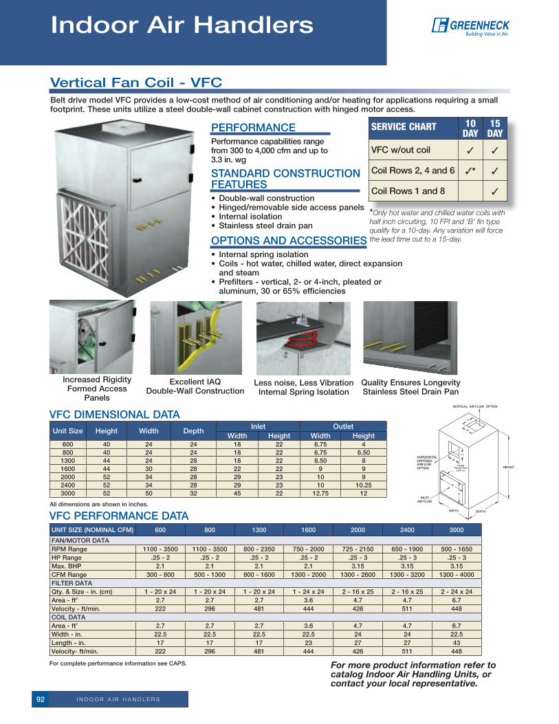
i n d o o R a i R h a n d l e R S92
QualityEnsuresLongevityStainless Steel Drain Pan
ExcellentIAQDouble-Wall Construction
All dimensions are shown in inches.
Unit Size Height Width DepthInlet Outlet
Width Height Width Height 600 40 24 24 18 22 6.75 4800 40 24 24 18 22 6.75 6.501300 44 24 28 18 22 8.50 81600 44 30 28 22 22 9 92000 52 34 28 29 23 10 92400 52 34 28 29 23 10 10.253000 52 50 32 45 22 12.75 12
VFC DIMENSIONAL DATA
For complete performance information see CAPS.
Increased rigidityFormed Access
Panels
Less noise, Less Vibration Internal Spring Isolation
SErvicE chart 10 daY
15 daY
VFC w/out coil 3 3
Coil rows 2, 4 and 6 3* 3
Coil rows 1 and 8 3
UNIT SIZE (NOMINAL CFM) 600 800 1300 1600 2000 2400 3000
FAN/MOTOr DATArPM range 1100-3500 1100-3500 800-2350 750 - 2000 725 - 2150 650-1900 500 - 1650HP range .25 - 2 .25 - 2 .25 - 2 .25 - 2 .25-3 .25-3 .25-3Max. BHP 2.1 2.1 2.1 2.1 3.15 3.15 3.15CFM range 300-800 500-1300 800 - 1600 1300-2000 1300-2600 1300-3200 1300-4000FILTEr DATAQty.&Size-in.(cm) 1 - 20 x 24 1 - 20 x 24 1 - 20 x 24 1 - 24 x 24 2 - 16 x 25 2 - 16 x 25 2 - 24 x 24Area - ft2 2.7 2.7 2.7 3.6 4.7 4.7 6.7Velocity - ft/min. 222 296 481 444 426 511 448COIL DATAArea - ft2 2.7 2.7 2.7 3.6 4.7 4.7 6.7Width - in. 22.5 22.5 22.5 22.5 24 24 22.5Length - in. 17 17 17 23 27 27 43Velocity- ft/min. 222 296 481 444 426 511 448
Vertical Fan Coil - VFCBelt drive model VFC provides a low-cost method of air conditioning and/or heating for applications requiring a small footprint. These units utilize a steel double-wall cabinet construction with hinged motor access.
STANDArD CONSTrUCTION FEATUrES• Double-wallconstruction• Hinged/removablesideaccesspanels• Internalisolation• Stainlesssteeldrainpan
OPTIONS AND ACCESSOrIES• Internalspringisolation• Coils-hotwater,chilledwater,directexpansion
and steam• Prefilters-vertical,2-or4-inch,pleatedoraluminum,30or65%efficiencies
PErFOrMANCEPerformance capabilities range from300to4,000cfmandupto3.3in.wg
VFC PErFOrMANCE DATA
For more product information refer to catalog Indoor Air Handling Units, or contact your local representative.
*Only hot water and chilled water coils with half inch circuiting, 10 FPI and ‘B’ fin type qualify for a 10-day. Any variation will force the lead time out to a 15-day.
Indoor Air Handlers

i n d o o R a i R h a n d l e R S 93
Vertical Fan Coil - VFCDDirect drive model VFCD provides a low-cost method of air conditioning and/or heating for applications requiring a small footprint. These units utilize a steel double-wall cabinet construction with hinged motor access.
OutletVetrtical Air Flow
Option
InletAir Flow
FilterProjection2 or 4 in.
FG
B C
A
D
E
ExcellentIAQDouble-Wall Construction
All dimensions are shown in inches.
Unit Size Height Width DepthInlet Outlet
Width Height Width Height 600 40 24 24 18 22 5.5 5.50800 40 24 24 18 22 7.25 5.501300 44 24 28 18 22 18 5.631600 44 30 28 22 22 18 5.632000 52 34 28 29 23 26 5.632400 52 34 28 29 23 26 5.633000 52 50 32 45 22 32.88 10.38
VFCD DIMENSIONAL DATA
For complete performance information see CAPS.
Increased rigidityFormed Access
Panels
Easy Slide Out Motor and Scroll
UNIT SIZE (NOMINAL CFM) 600 800 1300 1600 2000 2400 3000
FAN/MOTOr DATA
rPM range 960-1600 900-1500 870 - 1450 966-1610 660 - 1100 870 - 1450 660 - 1100
HP range .25 - 2 .25 - 2 .25 - 2 .25 - 2 .25-3 .25-3 .25-3
Max. BHP 3.8 3.8 7.8 9 7.8 5.6 7.1
CFM range 250-770 250-950 700-1640 900-1640 900-2400 1300-3000 1300-4000
FILTEr DATA
Qty.&Size-in.(cm) 1 - 20 x 24 1 - 20 x 24 1 - 20 x 24 1 - 24 x 24 2 - 16 x 25 2 - 16 x 25 2 - 24 x 24
Area - ft2 2.7 2.7 2.7 3.6 4.7 4.7 6.7
Velocity - ft/min. 222 296 481 444 426 511 448
COIL DATA
Area - ft2 2.7 2.7 2.7 3.6 4.7 4.7 6.7
Width - in. 22.5 22.5 22.5 22.5 25 25 22.5
Length - in. 17 17 17 23 27 27 43
Velocity- ft/min. 222 296 481 444 426 511 448
STANDArD CONSTrUCTION FEATUrES• Double-wallconstruction• Hinged/removablesideaccesspanels• Easyslideoutmotorandscroll• Stainlesssteeldrainpan
OPTIONS AND ACCESSOrIES• Coils-hotwater,chilledwater,directexpansion
and steam• Prefilters-vertical,2-or4-inch,pleatedoraluminum,30or65%efficiencies
PErFOrMANCEPerformance capabilities range from300to4,000cfmandupto1.5 in. wg
QualityEnsuresLongevityStainless Steel Drain Pan
VFCD PErFOrMANCE DATA
For more product information refer to catalog Indoor Air Handling Units, or contact your local representative.
*Only hot water and chilled water coils with half inch circuiting, 10 FPI and ‘B’ fin type qualify for a 10-day. Any variation will force the lead time out to a 15-day.
*
SErvicE chart 10 daY
15 daY
VFCD w/out coil 3 3
Coil rows 2, 4 and 6 3* 3
Coil rows 1 and 8 3

i n d o o R a i R h a n d l e R S94
Horizontal Fan Coil - HFCBGreenheck’s indoor air handling series, model HFCB, provides air conditioning and/or heating for buildings and specific spaces. These competitively priced units are designed with a wide range of construction features allowing it to be used in a number of applications such as schools, office buildings, apartments, medical facilities, and many other commercial applications.
Modular construction allows the engineer to configure the unit to meet their exact requirements. The modular construction also make this unit ideal for retrofit applications. Each model has a variety of options, accessories, and a wide performance range with quiet, trouble-free operation.
SErvicE chart 10 daY
HFC w/out coil 3
Coil rows 2, 4 and 6 3
STANDArD CONSTrUCTION FEATUrES• Double-wallconstruction• Removablesideaccesspanels• Internalisolation• Stainlesssteeldrainpan
OPTIONS AND ACCESSOrIES• Coils-hotwater,chilledwater,anddirect
expansion• Prefilters-vertical,2-inchpleated,30%
efficiencies
PErFOrMANCEPerformance capabilities rangefrom330to5,000cfmandupto3.3in.wg.
For more product information refer to catalog Model HFC, or contact your local representative.
OUTLET ArEA
Model HFCB008 0.30012 0.30016 0.36020 0.36030 1.00040 1.00
Dimensions shown in ft2
HFCB DIMENSIONAL DATA MODULE SIZING
SizeNominal
CFM
Mixing Box
Coil w/Filter
Blower Height Width Inlet OutletFlange
A B C DUnit
WidthHeight Width Height Width
008 800 22.0 23.5 29.0 17.75 26.5 13.5 22.25 10.52 7.31 1.50
012 1200 22.0 23.5 29.0 21.75 26.5 17.5 22.25 10.52 7.31 1.50
016 1600 22.0 23.5 29.0 21.75 33.0 17.5 28.75 11.88 8.75 1.50
020 2000 26.0 23.5 29.0 21.75 41.0 17.5 36.75 11.88 8.75 1.50
030 3000 28.0 23.5 29.0 33.25 41.0 29.0 36.75 11.88 13.63 1.50
040 4000 28.0 23.5 32.0 33.25 51.0 29.0 46.75 14 11.25 1.50
Dimensions shown in inches.
CBA
HFCB/D
AIRFLOW
D
HFC FILTEr CHArTFILTEr CHArT
SizeVertical
Filter Size (in.)
Qty.Face
Area (ft²)
008 16 x 25 1 2.8
012 20 x 25 1 3.5
016 16 x 20 2 4.4
020 20 x 20 2 5.6
030 16 x 20 4 8.9
040 16 x 25 4 11.1
Dimensions shown in inches.

i n d o o R a i R h a n d l e R S 95
Horizontal Fan Coil - HFCDDirect drive model HFCD, provides air conditioning and/or heating for buildings and specific spaces. These competitively priced units are designed with a wide range of construction features allowing it to be used in a number of applications such as schools, office buildings, apartments, medical facilities, and many other commercial applications.
Modular construction allows the engineer to configure the unit to meet their exact requirements. The modular construction also make this unit ideal for retrofit applications. Each model has a variety of options, accessories, and a wide performance range with quiet, trouble-free operation.
STANDArD CONSTrUCTION FEATUrES• Double-wallconstruction• Removablesideaccesspanels• Internalisolation• Stainlesssteeldrainpan
OPTIONS AND ACCESSOrIES• Coils-hotwater,chilledwater,anddirect
expansion• Prefilters-vertical,2-inchpleated,30%
efficiencies
PErFOrMANCEPerformance capabilities range from 450 to 2,475 cfm and up to 1.8 in. wg.
For more product information refer to catalog Model HFC, or contact your local representative.
OUTLET ArEA
Model HFCD008 0.28012 0.70016 0.70020 1.02030 —040 —
Dimensions shown in ft2
HFCD DIMENSIONAL DATA MODULE SIZING
SizeNominal
CFM
Mixing Box
Coil w/Filter
Blower Height Width Inlet OutletFlange
A B C DUnit
WidthHeight Width Height Width
008 800 22.0 23.5 29.0 17.75 26.5 13.5 22.25 5.88 7.75 1.50
012 1200 22.0 23.5 29.0 21.75 26.5 17.5 22.25 5.75 18.0 1.50
016 1600 22.0 23.5 29.0 21.75 33.0 17.5 22.25 5.75 18.0 1.50
020 2000 26.0 23.5 29.0 21.75 41.0 17.5 36.75 5.88 26.38 1.50
Dimensions shown in inches.
CBA
HFCB/D
AIRFLOW
D
SErvicE chart 10 daY
HFC w/out coil 3
Coil rows 2, 4 and 6 3
HFC FILTEr CHArTFILTEr CHArT
SizeVertical
Filter Size (in.)
Qty.Face
Area (ft²)
008 16 x 25 1 2.8
012 20 x 25 1 3.5
016 16 x 20 2 4.4
020 20 x 20 2 5.6
030 16 x 20 4 8.9
040 16 x 25 4 11.1
Dimensions shown in inches.

i n d o o R a i R h a n d l e R S96
All dimensions are shown in inches.
Unit Size
AB Width
Inlet Outletw/o
Filterw/ 2 in. Filter
w/ 4 in. Filter
Height Width Height Width
15 40 42 44 11 38 9.0 36 4.0 6.7520 40 42 44 14 38 12 36 6.50 6.7525 40 42 44 16 38 14 36 8.0 8.5030 45 47 49 18.5 38 16.5 36 9.0 9.045 45 47 49 18.5 50 16.5 48 9.0 1050 48 50 52 21 50 19 48 10.25 1065 52 54 56 26 50 24 48 12 12.7585 52 54 56 26 62 24 60 12 15
A
B
LFC DIMENSIONAL DATA
For more product information refer to catalog Indoor Air Handling Units, or
contact your local representative.
SErvicE chart 10 daY
15 daY
LFC 3 3
Coil rows 2, 4 and 6 3* 3
Coil rows 1 and 8 3
PErFOrMANCEPerformance capabilities range from 360to5,300cfmandup to 4 in. wg.
Low-Profile Fan Coil - LFC
*Only hot water and chilled water coils with half inch circuiting, 10 FPI and ‘B’ fin type qualify for a 10-day. Any variation will force the lead time out to a 15-day.
Mix Air Evenly Mixing Box Module
Less Noise, Less Vibration Internal Spring Isolation
ExcellentIAQDouble-Wall Construction
QuickEasyMaintenanceFilter Access
Increased rigidityFormed Access Panels
QualityEnsuresLongevityStainless Steel Drain Pan
• Low-profile-asshortas11inches• Double-wallconstruction• Twoaccesspanelspermodule• Internalisolation• Stainlesssteeldrainpan
• Heatingcoils(hotwaterandsteam)• Coolingcoils(chilledwaterandDX)• Reheatcoils• Prefilter• Mixingbox
• Internalspringisolation• Coils-hotwater,chilledwater,direct
expansion and steam• Prefilter-verticalorsloped,2-or
4-inch,pleatedoraluminum,30,65or95%efficiencies
•Mixing box - w/ or w/o dampers, w/ or w/o filters, inlet configuration any two of top, end, bottom, right or left
STANDArD CONSTrUCTION FEATUrES MODULE SELECTION OPTIONS AND ACCESSOrIES
Model LFC provides a low-cost method of air conditioning and/or heating a building or specific space. These units come standard with a low-profile, double-wall constructed cabinet designed to fit in tight ceiling spaces. They utilize two types of forward-curved wheels providing a wide performance range and quiet operation.

i n d o o R a i R h a n d l e R S 97
24 PLENUM
12 PLENUM
CHILLED WATER
COILHEATING
COILVERTICAL
FILTERFANMIXING BOX
w/DAMPER24
PLENUM12
PLENUM
CHILLED WATER
COILHEATING
COILVERTICAL
FILTERFANMIXING BOX
w/DAMPER
A
Mixing Box Plenum Filter Heating Cooling Fan
B C D E F
G
MSCF DIMENSIONAL DATA
All dimensions are in inches. For complete dimensional information, see CAPS submittal drawings.
unit Size
a B C de F g unit
inlet Outletw/o
Filterw/ Filter 12 in. 24 in. Vertical Sloped
Hot Water1 & 2 row
4 row HW & Steam
Height Width Height Width
15 11 24.5 12.75 24.5 12.75 24.5 12.75 15.5 24.5 25 11 38 9 36 4 6.7520 14 24.5 12.75 24.5 12.75 24.5 12.75 15.5 24.5 25 14 38 12 36 6.50 6.7525 16 27 12.75 24.5 12.75 27 12.75 15.5 24.5 29 16 38 14 36 8 8.5030 18.5 31 12.75 24.5 12.75 31 12.75 15.5 24.5 32 18.5 38 16.5 36 9 945 18.5 32 12.75 24.5 12.75 32 12.75 15.5 24.5 32 18.5 50 16.5 48 9 1050 21 32 12.75 24.5 12.75 32 12.75 15.5 24.5 38 21 50 19 48 10 10.2565 26 38 12.75 24.5 12.75 38 12.75 15.5 24.5 42 26 50 24 48 12 12.7585 26 38 12.75 24.5 12.75 38 12.75 15.5 24.5 42 26 62 24 60 12 15
Modular Small Cabinet Fan - MSCFModel MSCF provides a low-cost method of air conditioning and/or heating a building or specific space. These units come standard with a low-profile, double-wall constructed cabinet designed to fit in tight ceiling spaces. They utilize two types of forward-curved wheels providing a wide performance range and quiet operation. The MSCF is also available with a backward-inclined (BI) wheel.
For more product information refer to catalog Indoor Air Handling Units, or contact your local representative.
PErFOrMANCEPerformance capabilities rangefrom360to5,300cfm and up to 4.5 in. wg.
• Modularconstruction• Low-profile-asshortas11inches• Double-wallconstruction• Twoaccesspanelspermodule• Internalisolation• Stainlesssteeldrainpan
• Heatingcoils(hotwaterandsteam)• Coolingcoils(chilledwaterandDX)• Reheatcoils• Prefilterand/orpostfilters• Mixingbox• Preand/orpostaccessplenums
• Internalspringisolation• Coils-hotwater,chilledwater,direct
expansion and steam• Prefilter-verticalorsloped,2or4
inch,pleatedoraluminum,30,65or95%efficiencies
•Mixing box - w/ or w/o dampers, w/ or w/o filters, inlet configuration any two of top, end, bottom, right or left
STANDArD CONSTrUCTION FEATUrES MODULE SELECTION OPTIONS AND ACCESSOrIES
Easy InstallationModular Construction
Less Noise, Less Vibration Internal Spring Isolation
ExcellentIAQDouble-Wall Construction
QuickEasyMaintenanceFilter Module
Increased rigidityFormed Access Panels
QualityEnsuresLongevityStainless Steel Drain Pan
Mix Air Evenly Mixing Box Module
SErvicE chart 10 daY
15 daY
MSCF 3 3
Coil rows 2, 4 and 6 3* 3
Coil rows 1 and 8 3
*Only hot water and chilled water coils with half inch circuiting, 10 FPI and ‘B’ fin type qualify for a 10-day. Any variation will force the lead time out to a 15-day.

i n d o o R a i R h a n d l e R S98
^ Available for MSCF unit only. For complete performance information see CAPS.
unit SiZe 15 20 25 30 45 50 65 85
nOMinal CFM 800 1100 1350 1600 2250 2600 3350 4300
FAN/MOTOr DATA
rPM range 1100-3500 1100-3500 800-3050 750 - 2500 725 - 2400 650 - 2200 500 - 2000 500 - 2200
HP range .25 - 2 .25 - 2 .25-3 .25-3 .25-3 .25 - 5 .25 - 7.5 .25 - 10
Max. BHP 2.1 2.1 2.1 3.15 3.15 5.25 7.875 10.5
CFM range 300-800 600 - 1100 900-1800 1200 - 2400 1500-2900 1800-3600 2400 - 4200 3000-5800
VErTICAL FILTEr DATA
Qty.&Size-in. 2-9x18 1 - 12 x 12 2 - 14 x 18 1 - 16 x 16 2 - 16 x 24 2 - 18 x 24 2 - 24 x 24 1 - 12 x 241 - 12 x 24 1 - 16 x 20 2 - 24 x 24
Area - ft2 1.8 2.5 3.0 3.4 4.8 5.4 7.2 8.9
Velocity - ft/min. 444 440 450 471 469 481 465 483
^ SLOPED FILTEr DATA
Qty.&Size-in. 1 - 12 x 12 1 - 16 x 16 2 - 16 x 20 1 - 12 x 24 2 - 24 x 24 2 - 24x24 4 - 24x24 2 - 12 x 24 1 - 12 x 24 1 - 16 x 20 1 - 24 x 24 4 - 24 x 24
Area - ft2 2.5 3.4 3.8 5.3 7.2 7.2 14.4 17.8
Velocity - ft/min. 320 324 355 302 313 361 233 242
COIL DATA
Area - ft2 1.6 2.2 2.7 3.2 4.5 5.2 6.7 8.6
Width - in. 7.50 10.00 12.50 15.00 15.00 17.50 22.50 22.50
Length - in. 31.00 31.00 31.00 31.00 43.00 43.00 43.00 55.00
Velocity- ft/min. 500 500 500 500 500 500 500 500
LFC/MSCF Performance Data

i n d o o R a i R h a n d l e R S 99
ETL Listed for Fan Coil Unit and in accordance with UL/cUL1995.
UFT STANDArD CONDENSED PErFOrMANCE rANGES & DIMENSIONAL DATA
For complete information refer to catalog Underfloor Fan Terminal - Model UFT, or contact your local representative.
R
24 in.
24 in.Double-Scroll UFT
Single-Scroll UFT
raised floor support pedestals
Airflow
Airflow
SErvicE chart 10 daY
UFT without Coil 3
UFT with Hot Water 3
115,230&277Volt 3
MOdel CFMunit
HeigHt (in.)
FlOOr HeigHtS
12 14 16 18
uFt-10-1 600 10.38 3 3 3 3
uFt-13-1 851 13.13 3 3 3
uFt-10-2 1336 10.38 3 3 3 3
uFt-13-2 1742 13.13 3 3 3
Underfloor Fan Terminal - UFTThe Greenheck model UFT is designed for an underfloor air distribution system to provide cooling or heating to the perimeterzonesorinteriorrooms.Performancerangesfrom130to1798cfmwithstaticpressuresto0.875incheswg. Underfloor systems offer reduced energy and equipment costs, simple installation, cleaner, healthier air, more design flexibility and individual occupant flow control.
STANDArD CONSTrUCTION FEATUrES• Highercfmperterminal• Cost-effectiveinstallation• Integralreheat• Quietoperation• Easeofmaintenance
INSTALLATION - FAN PLACEMENTraised floor systems are designed to allow for cables and equipment to be run under the floor. To accomplish this task, the floor is supported with pedestals that are placed 24 inches apart. The UFT is designed specifically for the raised floor application, allowing it to fit perfectly between these pedestals, while allowing an outlet duct to be attached if desired.
raised floor heights range from 12 inches and above. Greenheck has designed the UFT in two heights, Series 10 and13toaccommodatethevariousheights.

c o i l S100
Greenheck specializes in manufacturing competitively priced, quality-engineered replacement and OEM coils. Every coil we build is leak tested under water with 450 PSIG of dry nitrogen to guarantee 100% quality assurance. Greenheck’s experienced team of application specialists are only a phone call away, ready to quickly respond to any questions you may have.
OurQuickBuild(QB)programensuresthatyourcoilswillbemanufactured to your specifications and shipped according to your needs.
Coil Type (Style)
Custom Booster
Chilled Water
Hot Water
direct expansion
CondenserStandard
SteamSteam
distributingHot
WaterStandard
Steam
Tube Diameter (inches)3/8 3 3 3 3
1/2 3 3 3 3
5/8 3 3 3 3 3 3 3 3
rowsMin rows 1 1 1 1 1 1 1 1Max rows 12 12 12 12 2 2 2 2
Fin Height (inches)Min
Fin height is dependent on tube diameter (see Tube Diameter chart)
6 6Max 24 24
Increments of 3 3Fin Length (inches)
Min Minimum fin length is 1 inch 6 6Max Max fin length is 250 inches w/ center supports every 50 inches 48** 48**
Increments of no restriction on fin length increments 1 1recommended Face Velocity (FPM)
Min 400 500 400 600 500 500 500 500Max 550 800 550 750 850 850 800 850
recommended Fluid Velocity (FPS - for water coils)Min 1.5 1.5 NA NA NA NA 1.5 NAMax 4.0 4.0 NA NA NA NA 4.0 NA
recommended Pressure Drop (ft. of H2O or psi)Min 1 1 1.5 3 1 1 1 1Max 20 10 9 10 125* 125* 10 125*
* Higher steam pressures will require heavier tube wall thicknesses. ** Booster coil fin lengths are dependent on fin height.
Tube Diameter3/8 1/2 5/8
Wall Thickness (inches)0.016 3 30.020 3 30.025 30.035 30.049 3
Fin TypeAluminum 3 3 3Copper 3Fins Per Inch (FPI)Min 10 12 6Max 20 16 14Fin TypeSine-wave 3 3Corrugated 3Flat 3Connection Size (inches)Min 0.5 0.5 0.5Max 4.0 4.0 4.0Fin Height (inches)Min 4.0 5.0 4.5Max 60 120 120Increments of 1.00 1.25 1.50
refrigerant Types
r-22R-134ar-404Ar-407Cr-410Ar-502
Casing MaterialStandard Optional
16 gauge galvanized steel
14 gauge galvanized steel
16 gauge stainless steel
.06or.09in.thick copper
Fluid Flow rates
For water coils, connections sizes are based on GPM of water
GPM 1-4 4-8 8-16 16-30 30-40 40-70 75-150Conn. 3/4 1 1 1/4 1 1/2 2 2 1/2 3
Fin Material
Aluminum CopperTube Diameter
3/8 3
1/2 3
5/8 3 3
Fin Thickness0.006 3 3
0.008 3
0.010 3
Fin TypeSine-wave 3 3
Corrugated 3
Flat 3
Casing Types
Std. (1.5-inch flange)
Standard Booster (1-inch flange)
Slip and driveEndplates onlyInverted S. P. flange
Connection Types
FPT - Female pipe thread
MPT - Male pipe thread
Sweat
To guarantee your coil is going to perform as required, check for AHrI Certification.
SErvicE chart 3 daY
5 daY
10 daY
Custom Coils 3 3 3
For more product information refer to Catalog Custom Coils, or contact your local representative.
Custom Coils
Custom Coils

D A M P E R S 101
Curtain and Multi-Blade Fire DampersGreenheck fire dampers are qualified under UL/cUL 555 Standard for fire dampers. Fire dampers are required by all building codes to maintain the required fire resistance ratings of walls, partitions, and floors when they are penetrated by air ducts or other ventilation openings. Fire dampers close automatically upon detection of heat (usually by the melting of a fusible link at 165°F) blocking the opening and preventing the spread of fire into the adjoining compartment or spaces.
StanDarD ConStrUCtion FeatUreS• Galvanizedsteel• Fabricatedtoyoursizerequirements• UL/cUL 555 Classified• Dynamic (DFD) and static (FD) rated models• Horizontalandverticalmounts
Type A Blades In Airstream
Type B*Blades Out Of
Airstream
Type C*100% Free Area
Type CO*100% Free Area
Type CR*100% Free Area
Type R*High Free Area
PoC UnMoUnteD
tranSition tyPeS - CUrtain
SSC oPtionS
Retaining Bar
Cross-Section A-A
WallboardSteel Stud Frame
Steel Stud Wall
Steel StudFrame
A-A
DamperSleeve
Type A Blades In Airstream
Type B*Blades Out Of
Airstream
Type C*100% Free Area
Type CO*100% Free Area
Type CR*100% Free Area
Type R*High Free Area
* For Blade Stack Dimensions, refer to specification sheets on www.greenheck.com
Service chart iN StOcK SizeS NeXtDaY
3 DaY
5 DaY
10 DaY
11/2 HoUr rateD CUrtain Fire DaMPerStandard Frame Model 150 - type a, B, B2, r, Cr, C, Co 3 3 3 3
Standard Frame (Sealed) Model 155 - type Cr, C, Co, r
3 3 3
integral Sleeve Model 150X - type a, B, r, Cr, C, Co
(DFD-150 X 12)aV 8 x 8, 10 x 10, 12 x 12, 18 x 18, 24 x 24
3 3 3 3
narrowline Model 110 - type a, B, B2 3 3 3 3
Ultra thin Model 100 - type a, B 3 3
Stainless Steel 150, 155 (304SS) 3
out of Wall oFD-150, oDFD-150 3 3 3
11/2 HoUr rateD roUnD Fire DaMPer
round FDr-510, DFDr-510, 3 3 3 3
SSFDr-510, SSDFDr-510 (304SS) 3
SeDFDr-510 Severe environment (316SS) 3
MULti-BLaDe Fire DaMPer
DFD-210, 230 3 3 3 3
SeDFD-210 (316SS) 3
DFDtF-210, DFDaF-310 3 3 3 3
3 HoUr rateD CUrtain Fire DaMPerStandard Frame Model 350 - type a, B, B2, r, Cr, C, Co 3 3 3 3
Standard Frame (Sealed) Model 355 - type Cr, C, Co 3 3 3
narrowline Model 310 - type a, B, B2 3 3 3 3
Ultra thin Model 300 - type a, B, B2 3 3
Stainless Steel 350, 355 3
oPtionS anD aCCeSSorieS• P.o.C. - one piece retaining angles (loose or mounted)• Flanged sleeves• SSCoption,ETL(curtainonly)• Duct access doors - hinged and cam-style (Stock sizes available: 6x6, 8x8, 10x10, 12x12, 14x14,
16x16, 18x18, 20x20, 24x24 - Stocked in WI, CA, and KY)• Sleeves - (20 Ga.): 10, 12, 14, 16, 21, 24 inches
(16 Ga.): 10, 12, 14, 16, 21, 24 inches (14 Ga.): 10, 12, 14, 16, 21, 24 inches
• Fusiblelinktemperatureoptions-165°F, 212°F & 286°F• 316stainlesssteel-severeenvironmentdampers• Breakaway• Sealedtransition/sleeve• Factorymountedaccessdoor
Dampers
Greenheck Fan Corp. certifies that the models DFD-210, DFD-230, DFDtF-210, SeDFD-210, and SSDFD-210 shown herein are licensed to bear the aMCa Seal. the ratings shown are based on tests and procedures performed in accordance with aMCa Publication 511 and comply with the requirements of the aMCa Certified ratings Programs. the aMCa Certified ratings Seal applies to air performance ratings only.

D A M P E R S102
Smoke DampersGreenheck’s smoke dampers are qualified under UL/cUL 555S, Standard for smoke dampers. Smoke dampers prevent the circulation of air and smoke through a duct or a ventilation opening in a smoke separation.
Type A Blades In Airstream
Type B*Blades Out Of
Airstream
Type C*100% Free Area
Type CO*100% Free Area
Type CR*100% Free Area
Type R*High Free Area
Type A Blades In Airstream
Type B*Blades Out Of
Airstream
Type C*100% Free Area
Type CO*100% Free Area
Type CR*100% Free Area
Type R*High Free Area
oCithe oCi control option is an
SPDt switch typically used to indicate whether the smoke
damper blades are open or closed.
Greenheck Fan Corporation certifies that the models SMD-201, 202, 203, 301, 302, 301M, 302M; SeSMD-201 and SSSMD-201 shown herein are licensed to bear the aMCa Seal. the ratings shown are based on tests and procedures performed in accordance with aMCa Publication 511 and comply with the requirements of the aMCa Certified ratings Programs. the aMCa Certified ratings Seal applies to air performance only.
triPLe Vee
airFoiL
roUnD
Service chart NeXtDaY
3 DaY
5 DaY
10 DaY
3V BLaDe StyLe (aMCa Licensed air Performance)(recommended for velocities up to 2000 fpm and 4 in. wg)
SMD-201, 202, 203 - leakage class i, ii, iii 3 3 3 3
airFoiL BLaDe StyLe(recommended for velocities up to 3000 fpm and 6 in. wg)SMD-301,302,SMD-301M,302M,SMD-301V-galvanized,leakage class i, ii 3 3 3 3
SMD-401, SMD-401M - aluminum, leakage class i 3 3 3 3
roUnD BLaDe StyLe(recommended for velocities up to 2000 fpm and 4 in. wg)
SMDr-501, 502 3 3 3 3
StainLeSS SteeL MoDeLS(recommended for velocities up to 2000 fpm and 4 in. wg)
SSSMDr-501, 502 (304SS) stainless steel round 3
SeSMD-201 (316SS) 3
SeSMDr-501 (316SS) 3
SSSMD-201 (304SS) 3 3 3
StanDarD ConStrUCtion FeatUreS• Galvanizedsteelandaluminum• Fabricated to your sizerequirements• UL/cUL 555S Classified• Factory mounted actuators (120 vac, 24 vac, 230 vac, and
Pneumatic)• three blade styles
• oCi - open/Closed indicator• transitions - oval, round
and rectangular • Factory sleeves -
(20 Ga.): 16, 21, 24 inches (16 Ga.): 16, 21, 24 inches (14 Ga.): 16, 21, 24 inches• Stainless steel bearings• eP switch, transformers,
momentary switch• P.O.C.onepieceretaining
angle (loose or mounted)
• Smokedetector• Momentaryswitch• 316stainlesssteelsevere
environment dampers•GTS-3>S-4•Securitybars• Breakaway•Quickconnections•S&Driveconnection• Factorymountedaccess
door
PerForManCePerformance capabilities up to 3000 fpm and 6 in. wg of static pressure.
type o type r
type C
oPtionS anD aCCeSSorieS
tranSition tyPeS
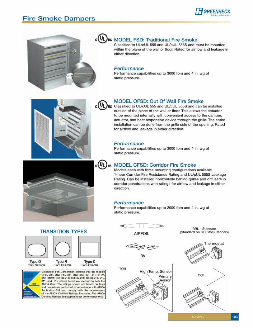
D A M P E R S 103
Fire Smoke Dampers
oCi
tor High T emp. Sensor
Primary Sensor
airFoiL
3V
MoDeL FSD: traditional Fire SmokeClassified to UL/cUL 555 and UL/cUL 555S and must be mounted within the plane of the wall or floor. rated for airflow and leakage in either direction.
PerformancePerformance capabilities up to 3000 fpm and 4 in. wg of static pressure.
MoDeL CFSD: Corridor Fire SmokeModels each with three mounting configurations available. 1-hour Corridor Fire resistance rating and UL/cUL 555S Leakage Rating.Canbeinstalledhorizontallybehindgrillesanddiffusersincorridor penetrations with ratings for airflow and leakage in either direction.
PerformancePerformance capabilities up to 2000 fpm and 4 in. wg of static pressure.
MoDeL oFSD: out of Wall Fire SmokeClassified to UL/cUL 555 and UL/cUL 555S and can be installed outside of the plane of the wall or floor. this allows the actuator to be mounted internally with convenient access to the damper, actuator, and heat responsive device through the grille. the entire installation can be done from the grille side of the opening. rated for airflow and leakage in either direction.
PerformancePerformance capabilities up to 3000 fpm and 4 in. wg of static pressure.
Greenheck Fan Corporation certifies that the models CFSD-211, 212; FSD-211, 212, 213, 231, 311, 311M, 312, 312M; SSFSD-211; SeFSD-211; oFSD-211, 212, 311, and 312 shown herein are licensed to bear the aMCa Seal. the ratings shown are based on tests and procedures performed in accordance with aMCa Publication 511 and comply with the requirements of the aMCa Certified ratings Programs. the aMCa Certified ratings Seal applies to air performance only.
Type C100% Free Area
Type O100% Free Area
Type R100% Free Area
tranSition tyPeSrrL - Standard
(StandardonQDStockModels)
Thermostat

D A M P E R S104
Fire Smoke Dampers
Service chart iNStOcK
NeXtDaY
3 DaY
5 DaY
10 DaY
Fire SMoKe
3V BLaDe StyLe (aMCa Licensed air Performance) (Maximum ratings up to 2000 fpm and 4 in. wg)
FSD-211, 212, 213 - 11/2 hour rated, leakage class i, ii, iiiFSD-212 (rrL only)
Sizes8x8, 10 x 10, 12 x 12, 16 x 16, 20 x 20, 24 x 24
3 3 3 3
FSD-231 - 3 hour rated, leakage class i 3 3 3 3
FSDr-511, 512 - 11/2 hour rated round 3 3 3 3
airFoiL BLaDe StyLe (Maximum ratings up to 3000 fpm and 4 in. wg)
FSD-311, FSD-311M, FSD-312, FSD-312M - 11/2 hour rated, leakage class i, ii
3 3 3 3
3 3 3 3
FSD-311V - 11/2 hour rated, leakage class i, vert. blade 3 3 3 3
FSD-331 - 3 hour rated, leakage class i, vert. blade 3 3 3 3
CorriDor Fire/SMoKe
3V BLaDe StyLe (aMCa Licensed air Performance) (Maximum ratings up to 2000 fpm and 4 in. wg)
CFSD-211 - 1 hour rated, leakage class i 3 3 3 3
CFSD-212 - 1 hour rated, leakage class ii 3 3 3 3
oUt-oF-WaLL Fire/SMoKe
3V Vee BLaDe StyLe (aMCa Licensed air Performance) (Maximum ratings up to 2000 fpm and 4 in. wg)
oFSD-211, 212 - 11/2 hour rated, leakage class i, ii 3 3 3 3
airFoiL BLaDe StyLe (Maximum ratings up to 3500 fpm and 8 in. wg)
oFSD-311, 312 - 11/2 hour rated, leakage class i, ii 3 3 3 3
StainLeSS SteeL MoDeLS
SSFSD-211 (304SS) 3 3 3
SeFSDr-511 (316SS), SSFSDr-511 (304SS) 3
SeFSD-211 (316SS) 3
FSD OFSD CFSD StanDarD COnStruCtiOn FeatureS
3 3 3 GalvanizedSteel
3 3 3 UL/cUL555 Classified/ UL/cUL555S Classified
3 3 3 Factory Mounted actuators (120 vac, 24 vac and Pneumatic)
3 Corridor rated
3 GalvanizedSleeve-wrappedwiththermalblanket
3 3 3 rrL - resettable Link
StanDarD ConStrUCtion FeatUreS
•P.O.C.-Onepieceretainingangle•RRL/OCI•TOR-TemperatureOverride•Transitions-oval,round and rectangular•Factorysleeves
(20 Ga.): 16, 21, 24 inches (16 Ga.): 16, 21, 24 inches (14 Ga.): 16, 21, 24 inches
•Stainlesssteelbushings
•EPswitch•Transformers•Factoryflanges•Smokedetector(FSDonly)•Momentaryswitch•PRV-PneumaticReliefValue•GreenheckTestSwitch-GTS-1,2, 3, 4• Breakawayflanges• Sealedtransitionsleeve• Factorymountedaccessdoor
oPtionS anD aCCeSSorieS

D A M P E R S 105
access Doorsaccess doors are designed for use in low to medium pressure duct systems. they provide a durable, practical, and inexpensive means of gaining access to damper components inside the ductwork.
StanDarD ConStrUCtion FeatUreS•Galvanizedsteel•Camstyle(CAD)•Hingedstyle(HAD)•Roundstyle(RAD)
Marine DampersMarine dampers are United States Coast Guard Class a-60 division and aBS approved. the marine dampers were testedatUnderwritersLaboratories(UL)inaccordancewithInternationalMaritimeOrganization’s(IMO)FireTestProcedure code. Fire and combination fire/smoke dampers can be used in marine and offshore ventilation systems.
StanDarD ConStrUCtion FeatUreS•Galvanizedsteel(IMO-310,IMO-311)•304StainlessSteel(SSIMO-310,SSIMO-311)•Airfoilbladedesign
Service chart 3 DaY
5 DaY
10DaY
SSiMo-310 3
iMo-310 3 3 3
iMo-311 3 3 3
SSiMo-311 3
Service chart iN StOcK SizeS* 10 DaY
CaD(Wi, Ca, FL & tX)
6x6, 8x8, 10x10, 12x12, 14x14, 16x16, 18x18, 20x20, 24x24
3
HaD(Wi, Ca, FL & tX)
6x6, 8x8, 10x10, 12x12, 14x14, 16x16, 18x18, 20x20, 24x24
3
raD insulated or Uninsulated(Wi, FL & tX)
6x6, 8x8, 10x10, 12x12, 14x14, 16x16 3
Greenheck Fan Corporation certifies that the models iMo-311 and SSiMo-311 shown herein is licensed to bear the aMCa Seal. the ratings shown are based on tests and procedures performed in accordance with aMCa Publication 511 and comply with the requirements of the aMCa Certified ratings Programs. the aMCa Certified ratings Seal applies to air performance ratings only.

D A M P E R S106
Ceiling radiation DampersGreenheck’s ceiling radiation dampers are qualified under UL/cUL 555C, Standard for ceiling dampers. Ceiling radiation dampers are designed to function as a heat barrier in duct outlets penetrating fire resistive membrane ceilings. these dampers may be used in lieu of hinged door type dampers, in ceiling designs listed in the UL/cUL Fire resistance Directory which allow penetrations.
3 3/4" Max.
Thermal Blanket
Lay-In Diffuser
Ceiling Radiation Damper
Tee Bar
eXaMPLe oF tHerMaL BLanKet aPPLiCation
reCtanGULar CrD-1
roUnD CrD-2
CrD-60X CrD-60B
CUrtain CrD-60
Service chart StOcK SizeS* 3 DaY
5 DaY
10DaY
rectangular Frame (CrD-1) 6x6, 8x8, 9x9,10x10, 12x12, 14x14,
22x10, 22x223 3 3
round Frame (CrD-2) 6, 8, 10, 12, 16 3 3 3
Curtain Frame (CrD-60) not applicable 3 3 3
Curtain Frame (CrD-60B) not applicable 3 3
Curtain Frame (CrD-60X) not applicable 3 3
rectangular Frame, Low-profile (CrD-1LP) 3 3 3
StanDarD ConStrUCtion FeatUreS• Galvanizedsteel• UL/cUL 555C Listed• Fabricatedtoyoursize
requirements• rectangular, round or
curtain type
oPtionS anD aCCeSSorieS• thermal blankets (1 in. mineral wool or
quilted ceramic) - 24 in. x 24 in.• adjustable volume controller
(not available on stock units)• top and bottom extension (5 & 10 day only)
* Stocked in WI & CA.

D A M P E R S 107
Volume Control DampersGreenheck’s control dampers are designed to control pressure, temperature or flow in an HVaC system. these dampers are available in parallel or opposed blade operation and can be supplied in both standard and low leakage construction. a control damper regulates pressure, temperature or flow by means of modulating or two position control. these dampers require operation by either manual, electric, or pneumatic actuators.
Service chart iNStOcK
NeXtDaY
3 DaY
5 DaY
10 DaY
3V BLaDe StyLe (aMCa Licensed air Performance)(recommended for velocities up to 1500 fpm and 2 in. wg)
VCD-15, 18 - non low leakage and low leakage 3 3 3 3
3V BLaDe StyLe (aMCa Licensed air Performance)(recommended for velocities up to 2000 fpm and 2.5 in. wg)
VCD-20 - non low leakage/VCD-20V (vertical) 3 3 3 3
VCD-23 - low leakage/VCD-23V (vertical)HorizontalSizes 10x10, 12x12,
16x16, 18x18, 24x243 3 3 3
GaLVaniZeD airFoiL BLaDe StyLe(recommended for velocities up to 4000 fpm and 8 in. wg)
VCD-33, 34 - low leakage 3 3 3 3
eXtrUDeD aLUMinUM airFoiL BLaDe StyLe(recommended for velocities up to 6000 fpm and 6 in. wg)
VCD-42, 43 - low leakage 3 3 3 3
VCD-40 - ultra low leakage 3 3 3 3
roUnD BLaDe StyLe(recommended for velocities up to 2000 fpm and 2.5 in. wg)
VCDr-50, 53 - non low leakage and low leakage 3 3 3 3
VCDrM-50, 53 - non low leakage and low leakage 3
SeVere enVironMent DaMPerS (316SS)
SeVCD-23 3
SeVCD-33 3
VCD-20V, 23V, 33V, 42V, 43V 3 3 3 3
StanDarD ConStrUCtion FeatUreS• Galvanizedsteelandaluminum• Fabricated to your sizerequirements• three blade styles
oPtionS anD aCCeSSorieS• transformers• Factory mounted actuators - manual,
electric and pneumatic• Flanged frame (3, 5, and 10-day)• Bronzeorstainlesssteelbearings• Stainless steel axles and linkages -
except VCD-15, VCD-18, VCDr-50/53• transitions - oval, round and rectangular• P.O.C.onepieceretainingangle• Factory Sleeves -
(20 Ga.): 16, 21, 24 inches (16 Ga.): 16, 21 inches (14 Ga.): 16, 21 inches
• Severeenvironmentdampers(316SS)
PerForManCePerformance capabilities up to 6000 fpm, and 8 in. wg of static pressure.
airFoiL 3V roUnD
Greenheck Fan Corporation certifies that the VCD-15, 18, 20, 23 and SeVCD-23 models shown herein are licensed to bear the aMCa Seal. the ratings shown are based on tests and procedures performed in accordance with aMCa Publication 511 and comply with the requirements of the aMCa Certified ratings Programs. the aMCa Certified ratings Seal applies to air performance ratings only.

D A M P E R S108
Manual Balancing DampersGreenheck’s manual balancing dampers are designed to regulate flow of air in an HVaC system. they are used to accomplish system balancing. each damper is equipped with a locking quadrant which fixes the damper blades in place after adjustment. these dampers are not intended to be used in applications as a positive shut off or for automatic control.
StanDarD ConStrUCtion FeatUreS• GalvanizedSteel• Fabricated to your sizerequirements
*note: MBDr-50 StoCK SiZeS aVaiLaBLeround Blade - 6, 8, 10, 12 - in Wi and Ca.
Extended Pin
Manual Hand Quadrant
Stand-off Bracket
eXPLoDeD VieW oF StanD-oFF BraCKet
oPtionS anD aCCeSSorieS• Stand-off brackets (accommodates for the
additional thickness of insulated duct)• Bronzebushings(MBD-15 only)• Factory sleeves (MBD-15 only) - (20 Ga.): 16, 21, 24 inches (16 Ga.): 16, 21 inches (14 Ga.): 16, 21 inches• Transitions-oval,round,andrectangular
(MBD-15 only)
StanDarD ConStrUCtion FeatUreS• Aluminumhatchannelframethermallybrokenwith
two polyurethane resin gaps and insulated on four sides with polystyrene
• Thermallybrokenaluminumairfoilbladeswithpolyurethane foam
• Siliconebladeandjambseals• Dualbearingwithacetalinnersleeveandflanged
outer bearing
insulated Control DamperICD-45damperistypicallyusedinapplicationswhereitisnecessarytominimizethetransferofheatorcoldpenetrationand reduce condensation.
Service chart NeXt DaY
3 DaY
5 DaY
10 DaY
SinGLe-BLaDe - MBD-10, 10 M 3 3 3 3
MULti BLaDe - MBD-15 3 3 3 3
roUnD BLaDe - MBDr-50* 3 3 3 3
Greenheck Fan Corporation certifies that the model iCD-45 shown herein is licensed to bear the aMCa Seal. the ratings shown are based on tests and procedures performed in accordance with aMCa Publication 511 and comply with the requirements of the aMCa Certified ratings Programs. the aMCa Certified ratings Seal applies to air performance ratings only.
Service chart 10 DaY
iCD-45 3

D A M P E R S 109
SerViCe CHartBarOMetriC reLieFeXtruDeD aLuMinuM recommended for velocities up to 2000 fpm or 2 in. wgMODeL FLanGe V* H* e* i* 5 DaY 10 DaYBr-10 none X X 3 3
Br-11 Discharge X X 3 3
Br-12 intake X X 3 3
Br-30 none X X 3 3
Br-31 Discharge X X 3 3
Br-32 intake X X 3 3
Br-40 none X X 3 3
Br-41 Discharge X X 3 3
Br-42 intake X X 3 3
industrial Dampersindustrial dampers are heavy duty construction for applications with high pressure and large air velocities.
ControLindustrial Control Dampers are heavy duty flange style dampers used to control airflow and provide shutoff.
Service chart 5 DaY
10 DaY
HeaVy DUty inDUStriaL(recommended for velocities up to 6000 fpm and 8 in. wg)
HCD 100 Series - pressure class i - unpainted 3 3
HCD 100 Series - pressure class i - painted 3
BaCKDraFtindustrial Backdraft Dampers are designed with heavy duty flange style frames to allow airflow in one direction and prevent reverse airflow.
Barometric relief DampersBarometric relief dampers are backdraft dampers having an adjustable start-open pressure. they are used on gravity ventilation systems or other low velocity applications.
Service chart 5 DaY
10 DaY
HB MoDeLSUnpainted 3 3
Painted 3
*V - Vertical Mount *H - HorizontalMount *e - exhaust (airflow up) *i - intake (airflow down)

D A M P E R S110
Backdraft DampersGreenheck’s backdraft dampers are used in systems to allow airflow in one direction and prevent airflow in the opposite direction. For example, exhaust dampers allow airflow out of buildings only, preventing airflow into the building.
*V - Vertical Mount *H - HorizontalMount *e - exhaust (airflow up) *i - intake (airflow down)
Service chart iNStOcK
3 DaY
5 DaY
10 DaY
Motor Packs 3 3 3 3
end Switches 3 3 3 3
PerForManCePerformance capabilities up to 3000 fpm and 10 in. wg of static pressure.
StanDarD ConStrUCtion FeatUreS• Galvanizedandextrudedaluminummodels• Fabricated to your sizerequirements• Stocksizesonsomemodels
MateriaL MODeL FLanGe V* H* e* i* SerViCe StOCk SizeS
GaLVanizeDrecommendedfor velocities up to 2000 fpm or
2 in. wg
WD-100 none X X Stock, 3 5, 10 8x8, 10x10, 12x12, 16x16, 18x18, 24x24, 30x30
WD-110 Discharge X X 3, 5, 10
WD-120 intake X X 3, 5, 10
WD-200 none X X X X Stock, 3, 5, 10 8x8, 10x10, 12x12, 14x14, 16x16, 18x18, 24x24, 30x30
WD-210 Motor Side X X X X 3, 5, 10
WD-220opposite
Motor SideX X X X 3, 5, 10
WD-300 intake X X 3, 5, 10
WD-320 Discharge X X Stock, 3, 5, 1010x10, 12x12, 14x14, 16x16, 18x18, 20x20, 22x22, 26x26, 32x32,
38x38
WD-330 none X X Stock, 3, 5, 10 9x9, 12x12, 14x14, 16x16, 18x18, 20x20, 23x23, 24x24, 35x35
WD-400 none X X 3, 5, 10
WD-410 none X X Stock, 3, 5, 10 8x8, 10x10, 12x12, 14x14, 16x16, 18x18, 20x20, 24x24, 30x30
WD-420 Discharge X X 3, 5, 10
WD-430 intake X X 3, 5, 10
WDr-53 none X X X X 10
StanDarDDutY
eXtruDeD aLuMinuM
recommended for velocities up to 2000 fpm or
2 in. wg
eS-10 none X X
1, 3, 5, 10
eS-11 Discharge X X
eS-12 intake X X
eS-30 none X X
eS-31 Discharge X X
eS-32 intake X X
eS-40 none X X
eS-41 Discharge X X
eS-42 intake X X
MeDiuMDutY
eXtruDeD aLuMinuM
recommended for velocities up to 3000 fpm or
10 in. wg
eM-10 none X X
1, 3, 5, 10
eM-11 Discharge X X
eM-12 intake X X
eM-30 none X X
eM-31 Discharge X X
eM-32 intake X X
eM-40 none X X
eM-41 Discharge X X
eM-42 intake X X
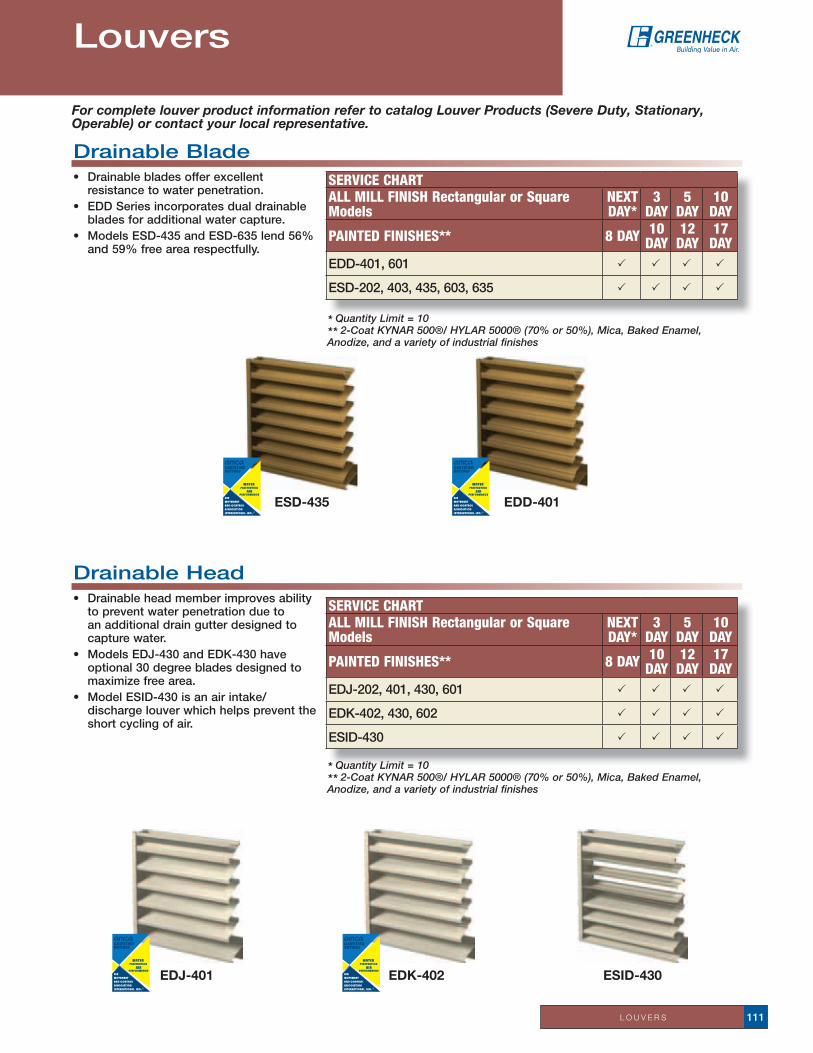
L O U V E R S 111
Drainable Blade • Drainablebladesofferexcellent
resistance to water penetration.• EDDSeriesincorporatesdualdrainable
blades for additional water capture.• ModelsESD-435andESD-635lend56%
and59%freearearespectfully.
Service chartall Mill FiNiSh rectangular or Square Models
NeXtDaY*
3DaY
5DaY
10DaY
PaiNteD FiNiSheS** 8 DaY 10 DaY
12 DaY
17 DaY
eDD-401, 601 P P P P
eSD-202, 403, 435, 603, 635 P P P P
Drainable Head • Drainableheadmemberimprovesability
to prevent water penetration due to an additional drain gutter designed to capture water.
• ModelsEDJ-430andEDK-430haveoptional 30 degree blades designed to maximizefreearea.
• ModelESID-430isanairintake/discharge louver which helps prevent the short cycling of air.
* Quantity Limit = 10 ** 2-Coat KYNAR 500®/ HYLAR 5000® (70% or 50%), Mica, Baked Enamel, Anodize, and a variety of industrial finishes
Louvers
Service chartall Mill FiNiSh rectangular or Square Models
NeXtDaY*
3DaY
5DaY
10DaY
PaiNteD FiNiSheS** 8 DaY 10 DaY
12 DaY
17 DaY
EDJ-202,401,430,601 P P P P
eDK-402, 430, 602 P P P P
eSiD-430 P P P P
eSiD-430
* Quantity Limit = 10 ** 2-Coat KYNAR 500®/ HYLAR 5000® (70% or 50%), Mica, Baked Enamel, Anodize, and a variety of industrial finishes
eSD-435 eDD-401
eDJ-401 eDk-402
For complete louver product information refer to catalog Louver Products (Severe Duty, Stationary, Operable) or contact your local representative.

L O U V E R S112
nondrainable • TraditionalstationaryJorKbladestyles.• Kbladehasasadditionaloffsetor“rainhook”forextraprotectionagainstwaterpenetration.• Designincorporateshiddenmullionsforcontinuousbladeappearancewhenmulti-widthsectionsareneeded.
recessed Mullion • RecessedMulliondesignoffersbetterbladealignmentforatruecontinuousbladeappearance.• Providesmorestructuralintegritybetweenmulti-widesections.• Easierinstallationwithminimalfieldadjustments.• Modelsareeasiertosealinfieldandthermalexpansionisaccountedforwithinthedesign.
Service chartall Mill FiNiSh rectangular or Square Models
NeXtDaY*
3DaY
5DaY
10DaY
PaiNteD FiNiSheS** 8 DaY 10 DaY
12 DaY
17 DaY
ESJ-401RM,602RM P P P
eSK-402rM, 602rM P P P
Service chartall Mill FiNiSh rectangular or Square Models
NeXtDaY*
3DaY
5DaY
10DaY
PaiNteD FiNiSheS** 8 DaY 10 DaY
12 DaY
17 DaY
ESJ-202,401,602 P P P P
eSK-402, 602 P P P P
thinline • RecessedMulliondesignoffersbetterbladealignmentforatruecontinuousbladeappearance.• Providesmorestructuralintegritybetweenmulti-widesections.• Easierinstallationwithminimalfieldadjustments.• Modelsareeasiertosealinfieldandthermalexpansionisaccountedforwithinthedesign.
Service chartall Mill FiNiSh rectangular or Square Models
NeXtDaY*
3DaY
5DaY
10DaY
PaiNteD FiNiSheS** 8 DaY 10 DaY
12 DaY
17 DaY
eSF-145 P P P P
ESJ-150 P P P P
eSU-130, 150 P P P P
eSU-130S, 150S P P P P
eSu-130S
eSF-145
eSu-150
eSJ-150
* Quantity Limit = 10 ** 2-Coat KYNAR 500®/ HYLAR 5000® (70% or 50%), Mica, Baked Enamel, Anodize, and a variety of industrial finishes
* Quantity Limit = 10 ** 2-Coat KYNAR 500®/ HYLAR 5000® (70% or 50%), Mica, Baked Enamel, Anodize, and a variety of industrial finishes
* Quantity Limit = 10 ** 2-Coat KYNAR 500®/ HYLAR 5000® (70% or 50%), Mica, Baked Enamel, Anodize, and a variety of industrial finishes
eSk-402eSJ-401
eSJ-401rM eSk-402rM

L O U V E R S 113
adjustable Blade• Designincorporatesoperablebladesthatcanbe
opened or closed to protect air intake and exhaust openings in exterior building walls.
• Louverbladesarecenterpivotedandcanbeoperatedmanually or by electric or pneumatic actuators.
• EADandEAHSeriesofferconcealedbladelinkage.• EADCSeriesofferbothconcealedbladelinkageanda
concealed electric actuator.• ModelEAH-690provides70%freeareawhenblades
are in full 90 degree open position.
Service chartall Mill FiNiSh rectangular or Square Models
NeXtDaY*
3DaY
5DaY
10DaY
PaiNteD FiNiSheS** 8 DaY 10 DaY
12 DaY
17 DaY
eaD-401, 601 P P P P
eaDC-401, 601 P
eaH-401, 690 P P P P
Combination Louver/Damper • Maintainsastationaryappearancewhenadjustableblades
are closed. • ECDSeriesofferexposedon-bladelinkage.• EACSeriesandModelEACN-601offerconcealedlinkage
and center pivot operable blades. • ModelEACA-601incorporatesairfoilblades.• EACCSeriesofferbothconcealedbladelinkageand
concealed electric actuator. • GCEandGCISeriesrequireanexhaustorintakefanfor
proper operation.
Service chartall Mill FiNiSh rectangular or Square Models
NeXtDaY*
3DaY
5DaY
10DaY
PaiNteD FiNiSheS** 8 DaY 10 DaY
12 DaY
17 DaY
eaC-401, 601 P P P P
eaCa-601 P P P P
eaCC-401, 601 P
eaCn-601 P P P P
eCD-401, 601 P P P P
GCe-202, 402 P P P P
GCi-202, 402 P P P P
* Quantity Limit = 10 ** 2-Coat KYNAR 500®/ HYLAR 5000® (70% or 50%), Mica, Baked Enamel, Anodize, and a variety of industrial finishes
eaDC-401
GCi-402 GCe-402eaCC-401
* Quantity Limit = 10 ** 2-Coat KYNAR 500®/ HYLAR 5000® (70% or 50%), Mica, Baked Enamel, Anodize, and a variety of industrial finishes
eaH-401 eaH-690 eaD-401
eaC-401 eaCa-601
eaCn-601 eCD-401

L O U V E R S114
Sightproof • Louversaredesignedtopreventvisualseethroughand
can be applied as air intake or discharge louvers or can be applied as louvered equipment screens.
• SESSeriesmosteconomicalofallsightproofmodels.• SEHSeriesincorporatesadrainableheadmemberfor
increased protection against water penetration.• SEDSeriesofferbothadrainableheadmemberand
drainable blades for maximum protection against water penetration.
• ModelSED-501offers57%freearea.• SEVSeriesofferaverticalsightproofbladedesign.
acoustical • Acousticallyinsulatedbladesprovidesoundabsorption
from escaping noise.• Availableinformedaluminumorsteelmaterial.• AFJSeriesmosteconomicalofallacousticalmodels.• ModelAFA-801offersthehighestfreeareaandlowest
airflow resistance and designed with acoustical blades. • ModelAFS-120offersthebestsoundabsorption
performance and incorporates sightproof blades.
Service chartall Mill FiNiSh rectangular or Square Models
NeXtDaY*
3DaY
5DaY
10DaY
PaiNteD FiNiSheS** 8 DaY 10 DaY
12 DaY
17 DaY
SeD-202, 401, 501 P P P P
SeH-202, 401 P P P P
SeS-202, 401 P P P P
SeV-401, 501 P P P P
SeS-401 SeV-401
Service chartall Mill FiNiSh rectangular or Square Models
NeXtDaY*
3DaY
5DaY
10DaY
PaiNteD FiNiSheS** 8 DaY 10 DaY
12 DaY
17 DaY
aFa-801 P
AFJ-601,801,120 P
aFS-120 P
* Quantity Limit = 10 ** 2-Coat KYNAR 500®/ HYLAR 5000® (70% or 50%), Mica, Baked Enamel, Anodize, and a variety of industrial finishes
* Quantity Limit = 10 ** 2-Coat KYNAR 500®/ HYLAR 5000® (70% or 50%), Mica, Baked Enamel, Anodize, and a variety of industrial finishes
aFa-801 aFJ-801 aFS-120
SeH-401 SeD-401

L O U V E R S 115
Fabricated• Fabricatedfromgalvanizedsteelandarelow-cost
compared to extruded aluminum models.• Allfabricatedmodelsareavailableinstainlesssteel
material.• FSJandFDSSerieshavestationarybladesonly.• FADandFAJSeriesareadjustableblademodels.
Service chartall Mill FiNiSh rectangular or Square Models
NeXtDaY*
3DaY
5DaY
10DaY
PaiNteD FiNiSheS** 8 DaY 10 DaY
12 DaY
17 DaY
FaD-402, 602, 635 P P P
FAJ-402,602 P P P
FDS-402, 602 P P P
FSJ-402,602 P P P
eHH-401 eVH-401
FSJ-402 FDS-402FaD-402 FaJ-402
* Quantity Limit = 10 ** 2-Coat KYNAR 500®/ HYLAR 5000® (70% or 50%), Mica, Baked Enamel, Anodize, and a variety of industrial finishes
Service chartall Mill FiNiSh rectangular or Square Models
NeXtDaY*
3DaY
5DaY
10DaY
PaiNteD FiNiSheS** 8 DaY 10 DaY
12 DaY
17 DaY
eHH-201, 401, 501, 601, 701 P P P P
eVH-201, 401, 602, 801 P P P P
Wind-Driven rain• Louversaredesignedtopreventvisualseethroughandcanbeappliedasairintakeordischargelouversorcanbe
applied as louvered equipment screens. • SESSeriesmosteconomicalofallsightproofmodels.• SEHSeriesincorporatesadrainableheadmemberforincreasedprotectionagainstwaterpenetration.• SEDSeriesofferbothadrainableheadmemberanddrainablebladesformaximumprotectionagainstwater
penetration.• ModelSED-501offers57%freearea.• SEVSeriesofferaverticalsightproofbladedesign.
* Quantity Limit = 10 ** 2-Coat KYNAR 500®/ HYLAR 5000® (70% or 50%), Mica, Baked Enamel, Anodize, and a variety of industrial finishes
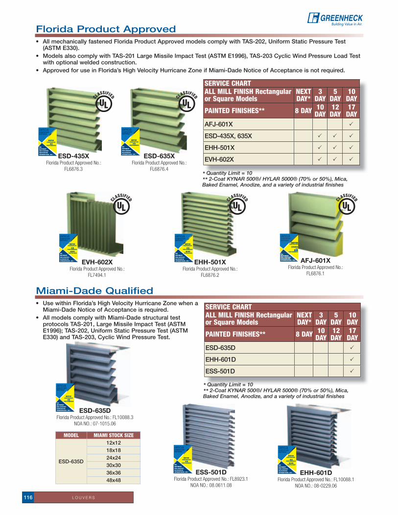
L O U V E R S116
Florida Product approved• AllmechanicallyfastenedFloridaProductApprovedmodelscomplywithTAS-202,UniformStaticPressureTest
(aStM e330).• ModelsalsocomplywithTAS-201LargeMissileImpactTest(ASTME1996),TAS-203CyclicWindPressureLoadTest
with optional welded construction. • ApprovedforuseinFlorida’sHighVelocityHurricaneZoneifMiami-DadeNoticeofAcceptanceisnotrequired.
Miami-DadeQualified• UsewithinFlorida’sHighVelocityHurricaneZonewhena
Miami-Dade notice of acceptance is required. • AllmodelscomplywithMiami-Dadestructuraltest
protocols taS-201, Large Missile impact test (aStM e1996); taS-202, Uniform Static Pressure test (aStM e330) and taS-203, Cyclic Wind Pressure test.
eSD-435XFlorida Product Approved No.:
FL6876.3
eSD-635XFlorida Product Approved No.:
FL6876.4
eHH-501XFlorida Product Approved No.:
FL6876.2
eVH-602XFlorida Product Approved No.:
FL7494.1
aFJ-601XFlorida Product Approved No.:
FL6876.1
Service chartall Mill FiNiSh rectangular or Square Models
NeXtDaY*
3DaY
5DaY
10DaY
PaiNteD FiNiSheS** 8 DaY 10 DaY
12 DaY
17 DaY
AFJ-601X P
eSD-435X, 635X P P P
eHH-501X P P P
eVH-602X P P P
eHH-601DFlorida Product Approved No.: FL10088.1
NOA NO.: 08-0229.06
eSD-635DFlorida Product Approved No.: FL10088.3
NOA NO.: 07-1015.06
eSS-501DFlorida Product Approved No.: FL8923.1
NOA NO.: 08.0611.08
Service chartall Mill FiNiSh rectangular or Square Models
NeXtDaY*
3DaY
5DaY
10DaY
PaiNteD FiNiSheS** 8 DaY 10 DaY
12 DaY
17 DaY
eSD-635D P
eHH-601D P
eSS-501D P
* Quantity Limit = 10 ** 2-Coat KYNAR 500®/ HYLAR 5000® (70% or 50%), Mica, Baked Enamel, Anodize, and a variety of industrial finishes
* Quantity Limit = 10 ** 2-Coat KYNAR 500®/ HYLAR 5000® (70% or 50%), Mica, Baked Enamel, Anodize, and a variety of industrial finishes
MODel MiaMi StOcK Size
eSD-635D
12x1218x1824x2430x3036x3648x48

L O U V E R S 117
For complete product information refer to catalog Model WIH Intake and WRH Relief, or contact your local representative.
DiMenSionaL Data
LoUVereD PentHoUSe - intaKe anD reLieF - PerForManCe Data (Per Square Foot of throat area)
* Quantity Limit = 10 ** 2-Coat KYNAR 500®/ HYLAR 5000® (70% or 50%), Mica, Baked Enamel, Anodize, and a variety of industrial finishes
MoDeL: W (LoUVereD PentHoUSe)
* Quantity Limit = 10 * Quantity Limit = 10 *
Service chart 5DaY
10DaY
PaiNteD FiNiSheS** 12DaY*
17DaY*
All ModelsandSizes P
Sizesupto48x48in. P P
MODeLSize ranGe LiMitS
a B C
LOuVereD PentHOuSe 12 in. - 80 in. 12 in. - 120 in. 121/4 in. - 493/4 in.
intakeStatiC PreSSure DrOP .008 .017 .03 .048 .069 .094 .123 .156 .192
tHrOat VeLOCitY 200 300 400 500 600 700 800 900 1000
reLieFStatiC PreSSure DrOP .024 .038 .06 .075 .097 .123 .152 .184 .22
tHrOat VeLOCitY 400 500 600 700 800 900 1000 1100 1200
Louvered Penthousesthe low silhouette louvered penthouses are designed for intake (Model WiH) or relief (Model WrH) applications with either natural gravity or positive pressure systems. these units feature a storm-proof aluminum louver with mitered cornersandcleanhorizontallines.Thedesignaffordslowerpressuredropswhilemaintaininglowhoodheights.All-aluminum construction assures lasting durability and appearance. removable cover is lined with fiberglass to prevent condensation.
Louvers are mounted 4 in. from the roof opening for added weather protection. each unit is factory made into four side sections and one cover. the units are shipped in pre-assembled sections that are easy to assemble on the jobsite without special tools.
Service chart Mill FiNiSh aNODizeD* PaiNteD**BVe 81⁄8 x 73⁄4 QDStock 5 Day 8 DayBVe 12 x 73⁄4 QDStock 5 Day 8 DayBVe 155⁄8 X 73⁄4 QDStock 5 Day 8 DayBVe 161⁄2 X 73⁄4 QDStock 5 Day 8 DayAllotherBVEsizes 5 Day 5 Day 12 DayAllBVFsizes 5 Day 5 Day 12 DayAllBVCsizes 5 Day na 12 Day***
* 204-R1, medium, dark, by others ** Primer, Baked Enamel, Acroflur, Kynar, Kynar-3 coat, Mica - all done at Greenheck*** Baked Enamel paint only
Brick Ventsa permanent means of ventilation for crawl spaces, hung ceilings, incinerator rooms, chimney flues, foundations, pipe spaces,andcorridors.Manystandardsizesandfinishesavailable.
StanDarD ConStrUCtion FeatUreS• Louversofextrudedaluminum(.080in)• Removablecover(s)linedwithfiberglassinsulation(asstandard)• Allunitsshippedknockeddown•.5in.Galvanizedmeshbirdscreen• Recommendedroofopeningdimensionisatleast21/2in.
largerthandampersize
oPtionS anD aCCeSSorieS• Aluminumbirdscreen• Aluminumorgalvanizedroofcurbs(Seepages38-39)• Curbseal• Gravityandmotorizeddampers•1in.hoodinsulation• Greenheckcoatings(Seecoatingspage119)
B
ThroatA
Curb Cap
C

O P T I O N S A N D A C C E S S O R I E S118
options andaccessoriesMounting optionsthe mounting options shown on this page (type a and B) relate to the Selection Guide For Vibration isolation as published in the latest aSHrae applications handbook, HVaC applications-Sound and Vibration Control.
DireCt MoUnt - tyPe ano base required. isolators are attached directly to equipment. Direct isolation can be used if equipment is unitary and rigid without the use of additional support. Direct isolation is not recommended for equipment having large overhung loads (e.g. motors on arr. 9 fans). if there is any doubt that equipment can be supported directly on isolators, use rails, bases or consult the factory.
StrUCtUraL BaSeS - tyPe B2Structural steel bases consist of structural steel members welded into a rigid one piece base. Motor slide rails are included where applicable. Bases are required for all arr. 1 and 3 fans with independently mounted motors. Structural steel bases are available without isolators, with rubber mounts or with spring mounts. all structural steel bases with spring mounts incorporate height saving brackets.
QuickBuildbasesarestandarddimensionswithfactorysuppliedmotor and drives.
rubber Mount
Shown W/o isolators or
BracketsSpring MountW/Height Saving Bracket
rubber
Spring
reStraineD SPrinG MoUntS - tyPe 4a 1 in. DeFLeCtionrestrained spring isolators consist of laterally stable, free-standing springs assembled into a steel housing. these assembliesaredesignedforverticalandhorizontalmotionrestraint. restrained spring isolators can be used for blocking during equipment installation and are provided withlevelingbolts.Springsprovide50%overloadcapacityand are color coded or identified to indicate load capacity. restrained spring mounts are recommended for equipment subject to wind loading or large torquing forces.
HoUSeD SPrinG MoUntS - tyPe 4B 1 in. DeFLeCtionHoused spring isolators consist of steel springs assembled into a telescoping housing with a top mounted adjusting bolt and an acoustical nonskid base. Housed spring isolators include resilient inserts to prevent metal-to-metal contact and provide snubbing for side loads. Springs provideanadditional50%overloadcapacityandarecolorcoded or identified to indicate load capacity.
rUBBer MoUntS - tyPe 2 1/4 in. & 1/2 in. DeFLeCtionneoprene mountings consist of a steel top plate and base plate completely embedded in colored (oil-resistant) neoprene for easy identification of capacity. neoprene mountings are furnished with a tapped hole in the center. this enables the equipment to be bolted securely to the rubber mount.
Free-StanDinG oPen SPrinG MoUntS tyPe 3 1 in. DeFLeCtionFree-standing spring isolators are unhoused laterally stable steel springs. they provide aminimumhorizontalstiffnessof0.8timesthe rated vertical stiffness and provide an additional50%overloadcapacity.Theseisolators are equipped with a top mounted adjusting bolt and an acoustical nonskid base. Springs are color coded or identified to indicate load capacity.
arr Fan tYPeMOuntinG SeLeCtiOn
DireCt MOunt(tYPe a)
StruCturaL BaSe(tYPe B2)
1 aF/BiSW XiPa/o/W X
3 aF/BiSW XaF/BiDW X
4 SFD X
9 aF/BiSW X XiPa/o/W X
10
SFB/SWB XaF/BiSW X XaF/BiSW XiPa/o/W X X

O P T I O N S A N D A C C E S S O R I E S 119
Coatings
Greenheck offers a choice of either protective or decorative coatings for many of the quick Build products.
Protective coatings are available in a choice of four electrostatic applied powders. Powders available range from polyester urethanes to high performance epoxy providing an available selection for most environments.
Powder coatings offer a number of advantages over most wet coatings. electrostatic painting involves applying a dry, charged particle to a grounded sheet metal. the results are uniform coverage and thickness with heavier coverage in the high charge areas (edges, corners, and pockets), that are difficult to reach with wet paint. another advantage is environmental friendliness. PerForManCe CoatinGSthe following is a brief description of the protective coatings offered. Complete descriptions and protective qualities can be found in GREENHECK’S SPECIAL CoAtING ENGINEERING BuLLEtIN (or consult your local representative).
SPartanWHite
iVoryMarBLe
DeSert SanD
HaMPtonBroWn
taUPe
MeDiUM BronZe
CLaSSiCBronZe
HoriZonBLUe
CaPriBLUe
GrayDarK Gray
CHarCoaL
MaCHinetooLGray
FLatBLaCK
GLoSSBLaCK
NotE: Colors are subject to change.
Decorative CoatingsFor projects where the fan exterior appearance is important and additional chemical resistance is not required, customers can choose from 16 standard decorative colors.
NotE: Colors are subject to change.
Heat Cured enamelsDecorative coatings are heat cured enamels applied either as wet paints or electrostatic powders. the range of colors offered provides for a color selection to meet most exterior requirements.
Permatector™Permatector™ is the standard coating applied to all steel fans. typical applications include corrosion resistance in indoor and outdoor environments. *040 gray (standard)
Hi-Pro Polyester (Used in lieu of air Dry Phenolic)this coating is resistant to salt water, chemical fumes, and moisture in more corrosive atmospheres. it has superior chemical resistance, excellent abrasion and outdoor UV protection. this coating has protective qualities that exceed air Dried Heresite. *Note: Standard Hi-Pro Polyester Lab Exhaust products are 041 gray
epoxyepoxy has excellent moisture resistance and moderate to good chemical resistance. Greenheck’s epoxy is light tan in color so it will resist fading and chalking when exposed to sunlight.
industrial epoxyindustrial epoxy is a high performance epoxy with excellent chemical resistance in interior applications to a wide variety of chemicals including acids, caustics, solvents, and high moisture.
industrial epoxy
Permatector™
epoxy
Hi-Pro Polyester*
PoWDer CoatinGS

O P T I O N S A N D A C C E S S O R I E S120
electrical accessories
Call our parts department toll free 1-800-355-5354 (for parts orders only) with fan model and serial number (located on fan name tag)
tiMe DeLay SWitCHMODeL GtDthe Model GtD time Delay Switch is available for keeping a fan or light operating for an extended period of time after the initiating switch has been turned off. the GtD assembly consists of a single-pole, single-throw switch, a timer and a cover plate.
ManUaL Starter SWitCHManual motor starting switches are available in five models. all models are UL/cUL Listed, HP rated, specification grade and feature neoprene rockers for quiet operation. Model MS-16 includes a pilot light. all models require a handy box by others.
DiSConneCt SWitCHeSFor safety in servicing fans not equipped with factory mounted disconnects, switches are available in five models. each model includes a switch assembly, handy box and cover plate.
Fan SPeeD ControLSpeed controls are available in two models for use with shaded pole and open permanent split capacitor motors in 115 volt single-phase only.Model 5W - For applications up to 5.0 amps. requires 2 x 4
handy box by others. Model 10W - For applications up to 10.0 amps. requires 4 x 4 handy box by others.
WeatHerPrOOF
Weatherproof Disconnect Switches in neMa rated weatherproof boxes for positive electrical shutoff and safety in servicing fans. neMa-3r toggle style switch models are listed below.
StanDarD
MODeL HP/VOLtS/PHStanDarD
n1tS-1 up to 1/2 120V 1phn1tS-2 up to 1 120V 1phn1tS-3 up to 2 120V 1phn1tS-4 up to 2 200/277 1phn1tS-6 up to 71/2 200/600 3ph
WeatHerPrOOFn3rtS-1 up to 1/2 120V 1phn3rtS-6 up to 7 200/600 3ph
SPeeDS MODeL HP/VOLtS/PH1 MS-1 1/2 120V 1ph1 MS-16 w/pl 1/2 120V 1ph1 MS-4 2 200/277 1ph1 MS-6 2 200/600 3ph3 MS-15 1/6 120V 1ph
Fire Stat
tYPe iiLimit control temp.
range 120-220 auto reset (Fire-Stat) 120V/8.0 amps - 220V/4 amp capacity.
tYPe iii
air Stat. adjustable temperature on (close circuit) ranging from
120°F to 200°F with off (open circuit) at 100°F. 120V/8.0 amps - 220V/4 amp capacity.
reVerSe aCtinG
tHerMOStat
Contacts close on temperature rise. adjustable for temperature range 30-110 degrees F.
rating to 120V/16 amps.
Need a replacement part for your fan?
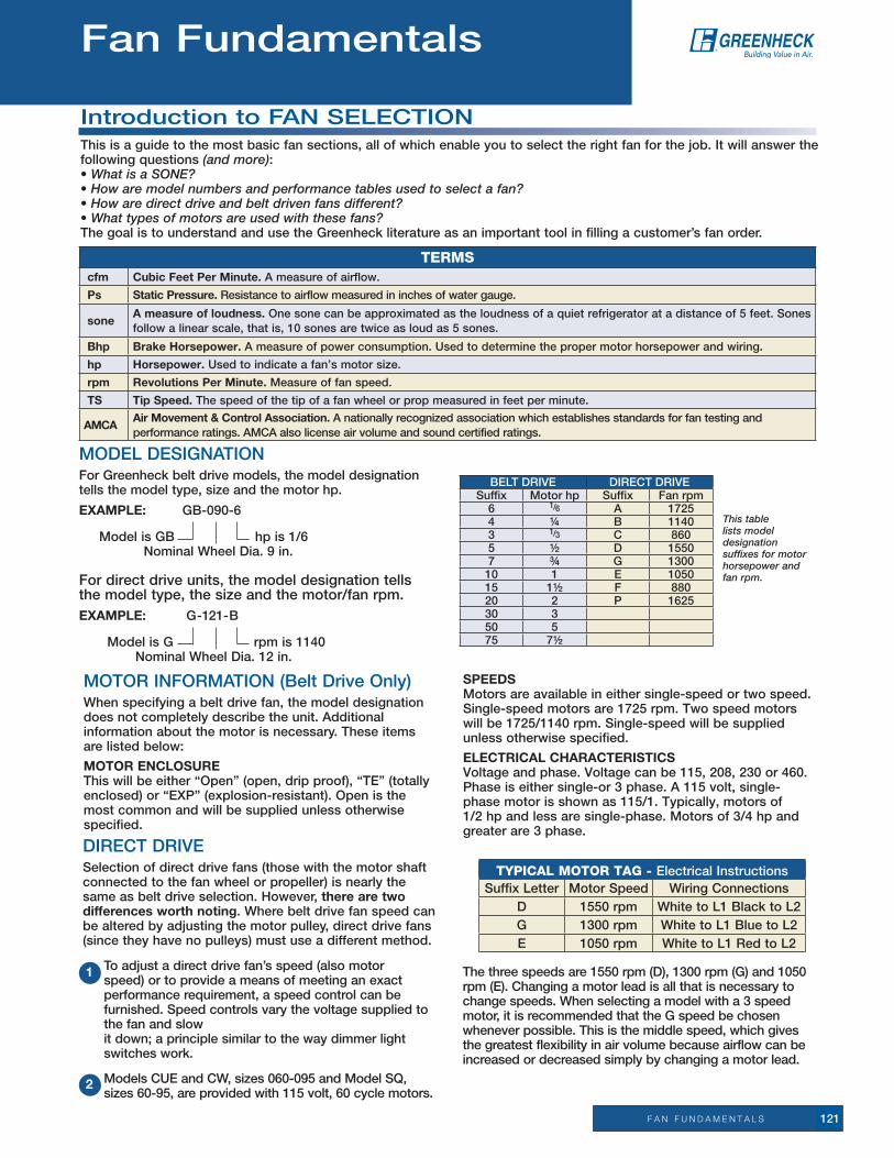
F A N F U N D A M E N T A L S 121
introduction to Fan SeLeCtionthis is a guide to the most basic fan sections, all of which enable you to select the right fan for the job. it will answer the following questions (and more): • What is a SONE? • How are model numbers and performance tables used to select a fan? • How are direct drive and belt driven fans different? • What types of motors are used with these fans? the goal is to understand and use the Greenheck literature as an important tool in filling a customer’s fan order.
Terms cfm Cubic Feet Per Minute. a measure of airflow.
Ps Static Pressure. resistance to airflow measured in inches of water gauge.
sonea measure of loudness. one sone can be approximated as the loudness of a quiet refrigerator at a distance of 5 feet. Sones follow a linear scale, that is, 10 sones are twice as loud as 5 sones.
Bhp Brake Horsepower. a measure of power consumption. Used to determine the proper motor horsepower and wiring.
hp Horsepower.Usedtoindicateafan’smotorsize.
rpm revolutions Per Minute. Measure of fan speed.
tS tip Speed. the speed of the tip of a fan wheel or prop measured in feet per minute.
aMCaair Movement & Control association.Anationallyrecognizedassociationwhichestablishesstandardsforfantestingandperformance ratings. aMCa also license air volume and sound certified ratings.
MoDeL DeSiGnation For Greenheck belt drive models, the model designation tellsthemodeltype,sizeandthemotorhp.
eXaMPLe: GB-090-6
Model is GB hp is 1/6 nominal Wheel Dia. 9 in.
For direct drive units, the model designation tells themodeltype,thesizeandthemotor/fanrpm.eXaMPLe: G-121-B
Model is G rpm is 1140 nominal Wheel Dia. 12 in.
Motor inForMation (Belt Drive only)When specifying a belt drive fan, the model designation does not completely describe the unit. additional information about the motor is necessary. these items are listed below:
MOtOr enCLOSure Thiswillbeeither“Open”(open,dripproof),“TE”(totallyenclosed)or“EXP”(explosion-resistant).Openisthemost common and will be supplied unless otherwise specified.
SPeeDS Motors are available in either single-speed or two speed. Single-speed motors are 1725 rpm. two speed motors will be 1725/1140 rpm. Single-speed will be supplied unless otherwise specified.
eLeCtriCaL CHaraCteriStiCS Voltage and phase. Voltage can be 115, 208, 230 or 460. Phase is either single-or 3 phase. a 115 volt, single-phase motor is shown as 115/1. typically, motors of 1/2 hp and less are single-phase. Motors of 3/4 hp and greater are 3 phase.
this table lists model designation suffixes for motor horsepower and fan rpm.
BeLt DriVe DireCt DriVeSuffix Motor hp Suffix Fan rpm
6 1/6 a 17254 1/4 B 11403 1/3 C 8605 1/2 D 15507 3/4 G 130010 1 e 105015 11/2 F 88020 2 P 162530 350 575 71/2
DireCt DriVeSelection of direct drive fans (those with the motor shaft connected to the fan wheel or propeller) is nearly the same as belt drive selection. However, there are two differences worth noting. Where belt drive fan speed can be altered by adjusting the motor pulley, direct drive fans (since they have no pulleys) must use a different method.
to adjust a direct drive fan’s speed (also motor speed) or to provide a means of meeting an exact performance requirement, a speed control can be furnished. Speed controls vary the voltage supplied to the fan and slow it down; a principle similar to the way dimmer light switches work.
ModelsCUEandCW,sizes060-095andModelSQ,sizes60-95,areprovidedwith115volt,60cyclemotors.
the three speeds are 1550 rpm (D), 1300 rpm (G) and 1050 rpm (e). Changing a motor lead is all that is necessary to change speeds. When selecting a model with a 3 speed motor, it is recommended that the G speed be chosen whenever possible. this is the middle speed, which gives the greatest flexibility in air volume because airflow can be increased or decreased simply by changing a motor lead.
1
2
Typical moTor Tag - electrical instructionsSuffix Letter Motor Speed Wiring Connections
D 1550 rpm White to L1 Black to L2G 1300 rpm White to L1 Blue to L2e 1050 rpm White to L1 red to L2
Fan Fundamentals

F A N F U N D A M E N T A L S122
BeLt DriVeone advantage of choosing a belt drive over a direct drive is that it is capable of adjusting the fan rpm, which enables the fan to move more air if necessary.
Motor pulleys are adjusted by loosening the set screw and turning the top half of the pulley (see illustrations at right). this causes the pulley diameter to change, which results in changing the fan rpm.
opening the pulley decreases fan rpm.Closing the pulley increases fan rpm.
Belt
aPPLiCationSVentilating a building simply replaces stale or foul air with clean, fresh air. although the ventilation process is required for many different applications, the airflow fundamentals never change:
UnDeSIReD aIR OUt, FReSH aIR In
the key variables that do change depending on applications are the fan model and the air volume flow rate (cfm). other considerations include the resistance to airflow (static pressure or Ps) and sound produced by the fan (Sones).
occasionally, a customer will require a fan to perform a particular function, yet does not know which model to use or even what cfm is necessary. in this case, some fan specification work must be done.
Fan specification is usually not a precise science and can be done confidently when the fan application is understood.
Based on the application, four parameters need to be determined. they are: Fan Model
Cubic Feet per Minute (cfm)
Static Pressure (Ps)
Loudness limit (sones)
Motor HorSePoWer
the motor horsepower for direct drive fans is alwayssizedbyGreenheckanddoesnotrequirefurther consideration. For belt drive models, the catalog identifies which horsepower is recommended. However, there are times when it is wise to bump thehorsepoweronesize.Forexample, the hp recommended for the GB-180 at 810 rpm ([email protected]”Ps)is1/3hp.
although a 1/3 hp motor is recommended, it is not necessarily a good motor selection for this application. our static pressure of 0.5 in. was only an estimate. it may actually turn out to be .625 in.
if this is the case, we will need a 1/2 hp motor because our fan will have to run at almost 810 rpm (refer to performance box - 2052 cfm at 0.625 in. Ps). therefore, choosing a 1/2 hp motor in this case is exercising good judgement.
the complete model designation for this application is GB-180-5.
nOte: the GB-180-5 has an rpm range of 700-940. this means that if the static pressure is less than estimated, say 0.25 in. Ps, the fan can be slowed down to accommodate this condition.
the information that follows will help walk you through this type of problem and enable you to select the right fan for the job.
Fan MoDeLFans all perform the basic function of moving air from one space to another. But the great diversity of fan applications creates the need for manufacturers to develop many different models. each model has benefits for certain applications, providing the most economical means of performing the air movement function. the trick for most users is sorting through all of the models available to find one that is suitable for their needs.
ProPeLLer vs. CentriFUGaL WHeeLPropeller fans provide an economical method to move large air volumes (5,000+ cfm) at low static pressures (0.50 in. or less). Motors are typically mounted in the airstream which limits applications to relatively clean air at maximum temperatures of 110°F.
Centrifugal fans are more efficient at higher static pressures and are quieter than propeller fans. Many centrifugal fan models are designed with motors mounted out of the airstream to ventilate contaminated and high temperature air.
introduction to Fan SeLeCtion

F A N F U N D A M E N T A L S 123
Exhaust fan to be sized
8 ft.
40 ft.
30 ft.
Louvers to supplyMakeup air
DeterMininG CFMafter the model is known, the cfm must be determined. Consult local code requirements or the table below for suggested air changes for proper ventilation.
the ranges specified will adequately ventilate the corresponding areas in most cases. However, extremeconditionsmayrequire“MinutesperChange”outsideofthespecifiedrange.Todetermine the actual number needed within a range,
consider the geographic location and average duty level of the area. For hot climates and heavier than normal area usage, select a lower number in the range to change the air more quickly. For moderate climates with lighter usages, select a higher number in the range.
to determine the cfm required to adequately ventilate an area, divide the room volume by the appropriate“MinutesperChange”value.
SaMPLe ProBLeMa building requires an exhaust fan to ventilate a general office (see diagram below) which measures 30 ft. x 40 ft. x 8 ft. the office is often crowded.
SOLutiOn: the total room volume is 30 ft. x 40 ft. x 8 ft. = 9600 cubic feet. From the chart, the range for general offices is 2-8 minutes per change. Since the office has heavier than normal usage, 4 minutes per change is recommended. therefore, the required exhaust is:
9600 ft3
= 2400 cfm 4 min.
Since the air to be exhausted is relatively clean, this is an ideal application for a model GB fan.
nOte: in this example, make-up air was provided through a set of louvers at the wall farthest from the exhaust fan. if there were no provisions for make-up air in this room, a supply fan would also havetobesized.Thesupplycfmshouldequaltheexhaust cfm. Supply fan location should be as far as possible from the exhaust fan.
SuGGeSteD air CHanGeS FOr PrOPer VentiLatiOn room Volume cfm = room Volume = L x W x H (of room) Min./Chg.
introduction to Fan SeLeCtion
area Min./Chg. area Min./Chg. area Min./Chg.
assembly Hall 3-10 Dance Hall 3-7 Machine Shop 3-6
attic 2-4 Dining room 4-8 Mill 3-8
auditorium 3-10 Dry Cleaner 2-5 office 2-8
Bakery 2-3 engine room 1-3 Packing House 2-5
Bar 2-4 Factory 2-7 Projection room 1-2
Barn 12-18 Foundry 1-5 recreation room 2-8
Boiler room 1-3 Garage 2-10 residence 2-6
Bowling alley 3-7 Generator room 2-5 restaurant 5-10
Cafeteria 3-5 Gymnasium 3-8 restroom 5-7
Church 4-10 Kitchen 1-5 Store 3-7
Classroom 4-6 Laboratory 2-5 transfer room 1-5
Club room 3-7 Laundry 2-4 Warehouse 3-10

F A N F U N D A M E N T A L S124
StatiC PreSSure GuiDeLineS
StatiC PreSSUre GUiDeLineS
nonducted 0.05 in. to 0.20 in.
Ducted
0.2 in. to 0.40 in. per 100 feet ofduct (assuming duct air velocity falls within 1000-1800 feet perminute)
Fittings 0.08 in. per fitting (elbow, register,grill, damper, etc.)
kitchen Hood exhaust 0.625 in. to 1.50 in.
Static pressure requirements are significantly affected by the amount of make-up air supplied to an area. insufficient make-up air will increase static pressure and reduce the amount of air that will be exhausted. remember, for each cubic foot of air exhausted, one cubic foot of air must be supplied.
DeterMininG StatiC PreSSUre (Ps)the pressures generated by fans in ductwork are very small. yet, accurately estimating the static pressure is critical to proper fan selection.
Fan static pressure is measured in inches of water gauge. one pound per square inch is equivalent to 27.7 in. of water gauge. Static pressures in fan systems are typically less than 2 in. of water gauge, or 0.072 Psi. the drawing below illustrates how static pressures are measured in ductwork with a manometer.
a pressure differential between the duct and the atmosphere will cause the water level in the manometer legs to rest at different levels. this difference is the static pressure measured in inches of water gauge.
in the case of the exhaust fan below, the air is being drawn upward through the ductwork because the fan is producing a low pressure region at the top of the duct. this is the same principle that enables beverages to be sipped through a straw.
the amount of static pressure that the fan must overcome depends on the air velocity in the ductwork, the number of duct turns (and other resistive elements), and the duct length. For properly designed systems with sufficient make-up air, the guidelines in the table below can be used for estimating static pressure:
DuctAirflow
AtmosphericPressure
Manometer
Water
1 in.
Airflow out ofrestaurant
Grill
Damper
Airflow toexhaust fan
4 ft.
6 ft.
Ductworkexhaust Fan
* nOte: For convenience in using selection charts, round this value up to the nearest 1/8 in., which would be 0.50 Ps.
iMP
or
tan
t!
introduction to Fan SeLeCtion
to calculate the system losses, one must know the ductwork system configuration (see Ductwork figure).
Thisductissizedforairvelocitiesof1400feetperminute. referring to the static pressure chart, that will result in about 0.3 in. per 100 feet. Since we have 10 feet of total ductwork, our pressure drop due to the duct is:
there is also a 0.08 in. pressure drop for each resistive element or fitting. For this example, there are 5 fittings: one grill, two duct turns, one damper and louver in the wall of the office. the total pressure drop for fittings is:
5 x 0.08 in. = 0.4 in.
therefore, the total pressure drop is:
0.03 in. + 0.40 in. = 0.43 in.*.3 in.
x 10 ft. = .03 in.100 ft.

F A N F U N D A M E N T A L S 125
Example
Solution
SoUnD LeVeLSin many cases, the sound generated by a fan must be considered. For the fan industry, a common unit for expressing sound pressure level is the sone. in practical terms, the loudness of one sone is equivalent to the sound of a quiet refrigerator heard from five feet away in an acoustically average room.
Sones are a linear measurement of sound pressure levels. For example, a sound level of 10 sones is twice as loud as 5 sones.
refer to the Suggested Limits for room Loudness chart to determine the acceptable sone range for the application. as a general guideline, choose a fan that has a sone value within the range specified.
nOte: rooms with a hard construction (concrete block, tile floors, etc.) reflect sound. For these rooms, select fans on the lower end of the range. rooms with soft construction or those with carpeting and drapes, etc., absorb sound. For these rooms, fans near the higher end of the range may be selected.
For example, an exhaust fan for an officeinthe“SuggestedLimitsforRoomLoudness”chartbelowsaysthatofficesshould have a loudness range from 4 to 12 sones. Comparing a GB-141, GB-161 and GB-180 fan for approximately 3100 cfm at 0”PsonlytheGB-180hasasonevalueofless than 12. therefore, the GB-180 is the best selection for this application.
introduction to Fan SeLeCtion
Fan LaWS
]
in a steady-state system, as the fan rpm changes, cfm, Ps and BHp (horsepower) also change. the equations below, known better as fan laws, show the relationship between these performance parameters.
nOte:A25%increaseinrpmresultsina95%increaseinhorsepower.Consideringthis,initialfanselectionsshouldbesizedwithmotorhorsepowersgreaterthannecessaryifanyincreaseinfanrpmislikelyinthefuture.
ADJUSTINGFANPERFORMANCEthere is a direct relationship between cfm and rpm within a system. Doubling the fan rpm will double-the cfm delivered.sample: the example at the right shows a fan curve at 700 rpm which had an operating point of 1000 cfm at 0.25 in. Ps. What rpm is required to move 2000 cfm through the same system?solution: Within a system, cfm is directly related to rpm. therefore, the new rpm (rpm2) can be determined from the following equation:
referring to figure at right, this results in sliding up the system resistance curve from 700 rpm to 1400 rpm.notice that as we doubled our airflow from 1000 cfm to 2000 cfm, the Ps went up from 0.25 in. to 1.0 in. it must be kept in mind that we are not changing the system, only increasing fan speed. therefore, we must remain on the system resistance curve. Within a system, Ps varies as the square of cfm. Since cfm and rpm are directly proportional, an equation relating Ps and rpm can be derived as follows:
For our example,
this verifies the operating point on the 1400 rpm curve (2000 cfm at 1.0 in. Ps). With this example, it should be clear how cfm, rpm and Ps tie together in a steady-state system. Varying operating points
this equation relates horsepower to rpm. the change in horsepower can be determined when the rpm is increased by 25%.Thisisshownbelow:
Bhpnew = (1.25)3 x Bhpold = 1.95 x Bhpold
cfmnew = ( rpmnew ) x cfmoldrpmold
Bhpnew = ( rpmnew ) 3
x Bhpoldrpmold
Psnew = ( rpmnew )2
x Psoldrpmold
rpm2 = rpm1 x ( cfm2 )cfm1
= 700 rpm x ( 2000 cfm ) = 1400 rpm1000 cfm
Ps2 = Ps1 x ( rpm2 ) ²
rpm1
Ps2 = 0.25 in. x ( 1400 rpm ) ²= 1.0 in.
700 rpm
SuGGeSteD LiMitS FOr rOOM LOuDneSSSones DBa1.3-4 32-48 Private homes (rural and suburban)1.7-5 36-51 Conference rooms2-6 38-54 Hotel rooms, libraries, movie theatres, executive offices2.5-8 41-58 Schools and classrooms, hospital wards, and operating rooms3-9 44-60 Courtrooms, museums, apartments, private homes (urban)4-12 48-64 restaurants, lobbies, general open offices, banks5-15 51-67 Corridors and halls, cocktail lounges, washrooms and toilets7-21 56-72 Hotel kitchens and laundries, supermarkets12-36 64-80 Light machinery, assembly lines15-50 67-84 Machine shops25-60 74-87 Heavy machineryFrom AMCA Publication 302 (Application of Sone Ratings for Non Ducted Air Moving Devices with Room-Sone-dBA correlations).

R E P D I R E C T O R Y126 * Denotes representatives who carry local inventory.
Greenheck Sales office representatives
Greenheck repDirectory
aLaBaMa*Birmingham - air-tech incorporated 205-942-7081*(Pensacola, FL) - air-tech of Pensacola 850-433-6443*Mobile - air-tech of Pensacola 850-433-6443aLaSkaanchorage - Stinebaugh & Company 907-345-8021arizOna*Phoenix - air Specialty Products 480-377-9255tucson - air Specialty Products 520-623-0656arkanSaSLittleRock-JohnPrinceCompany 501-666-5488(Memphis, tn) - air Components inc. 901-382-1884Springdale-JohnPrinceCompany 479-756-5240CaLiFOrnia*anaheim - norman S. Wright/airelink Mech. equip. LLC 714-632-9800Chico - norman S. Wright Mechanical equipment 530-345-9289Fresno - norman S. Wright Mechanical equipment 559-271-3200*Los angeles - norman S. Wright/airelink Mech. equip. LLC 818-367-6100Pismo Beach - norman S. Wright Mechanical equipment 805-773-2810*Sacramento - norman S. Wright Mechanical equipment 916-381-6666*San Diego - Dave Dennison Co. inc. 619-440-5061*San Francisco - norman S. Wright Mechanical equipment 415-467-7600Santa Clara - norman S. Wright Mechanical equipment 408-748-1304Santa rosa - norman S. Wright Mechanical equipment 707-568-3903COLOraDOColorado Springs - CFM Company 719-528-1116*Denver - CFM Company 303-761-2291GrandJunction-CFMCompany 970-243-4377Fort Collins - CFM Company 970-493-7293COnneCtiCut*newington - Buckley associates inc. 860-666-0555Stratford - Buckley associates inc. 203-380-2405DeLaWare*(Phil, Pa) - Del-ren associates inc. 856-541-1776Seaford - Ward-Boland associates inc. 302-629-7006FLOriDa*Ft. Lauderdale/Miami - Cors-air 954-456-4300Ft. Myers - Commercial air Management inc. 239-277-0029Jacksonville-StanWeaver&Company 904-695-9295*orlando - Stan Weaver & Company 407-581-6940*Pensacola - air-tech of Pensacola 850-433-6443tallahassee - air-tech of Pensacola 850-433-6443*tampa - Stan Weaver & Company 800-783-6915West Palm Beach - Cors-air 561-844-9767
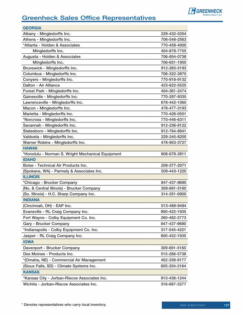
R E P D I R E C T O R Y* Denotes representatives who carry local inventory. 127
Greenheck Sales office representatives
GeOrGiaalbany - Mingledorffs inc. 229-432-5254athens - Mingledorffs inc. 706-548-2563*atlanta - Holden & associates 770-458-4000 Mingledorffs inc. 404-878-7755augusta - Holden & associates 706-854-0738 Mingledorffs inc. 706-651-1950Brunswick - Mingledorffs inc. 912-265-5193Columbus - Mingledorffs inc. 706-322-3870Conyers - Mingledorffs inc. 770-918-9132Dalton - air alliance 423-622-5525Forest Park - Mingledorffs inc. 404-361-2474Gainesville - Mingledorffs inc. 770-297-9335Lawrenceville - Mingledorffs inc. 678-442-1060Macon - Mingledorffs inc. 478-477-3193Marietta - Mingledorffs inc. 770-426-0551*norcross - Mingledorffs inc. 770-446-6311Savannah - Mingledorffs inc. 912-236-8122Statesboro - Mingledorffs inc. 912-764-8841Valdosta - Mingledorffs inc. 229-245-8200Warner robins - Mingledorffs inc. 478-953-3727HaWaii*Honolulu - norman S. Wright Mechanical equipment 808-678-3911iDaHOBoise - technical air Products inc. 208-377-2071(Spokane, Wa) - Parmely & associates inc. 509-443-1220iLLinOiS*Chicago - Brucker Company 847-437-9690(no. & Central illinois) - Brucker Company 309-691-5160(So. illinois) - H.C. Sharp Company inc. 314-351-6900
inDiana(Cincinnati, oH) - eaP inc. 513-489-9494
evansville - rL Craig Company inc. 800-422-1935
Fort Wayne - Colby equipment Co. inc. 260-482-3773
Gary - Brucker Company 847-437-9690
*indianapolis - Colby equipment Co. inc. 317-545-4221
Jasper-RLCraigCompanyInc. 800-422-1935
iOWa
Davenport - Brucker Company 309-691-5160
Des Moines - Products inc. 515-288-5738
*(omaha, ne) - Commercial air Management 402-339-9177
(Sioux Falls, SD) - Climate Systems inc. 605-334-2164
kanSaS
*KansasCity-Jorban-RiscoeAssociatesInc. 913-438-1244
Wichita-Jorban-RiscoeAssociatesInc. 316-687-3277

R E P D I R E C T O R Y128 * Denotes representatives who carry local inventory.
Greenheck Sales office representatives
kentuCkY
(Cincinnati, oH) - eaP inc. 513-489-9494
(Huntington, WV) - Mason & Barry inc. 304-755-0781
Louisville - rL Craig Company inc. 502-244-1600
LOuiSiana
Baton rouge - air-Side equipment inc. 225-275-6930
new orleans - air-Side equipment inc. 504-837-2346
Shreveport - reed Mechanical equipment inc. 318-687-8818
Maine
*(Manchester, nH) - Buckley associates inc. 603-669-3566
Portland - Buckley associates 207-773-0078
MarYLanD
Baltimore - Ward-Boland associates inc. 410-363-1833
Hagerstown - Ward-Boland associates inc. 301-791-0187
Salisbury - Ward-Boland associates inc. 302-629-7006
*Silver Spring - C.G. Wood Company inc. 240-241-5300
MaSSaCHuSettS
*Boston - Buckley associates inc. 781-878-5000
*Pittsfield - Buckley associates inc. 518-438-7423
*Springfield- Buckley associates inc. 860-666-0555
MiCHiGan
*Detroit - Michigan air Products 248-837-7000
escanaba - Vyron Corporation 715-355-0200
Grand rapids - Michigan air Products 616-534-8000
Saginaw - Michigan air Products 989-754-0409
MinneSOta
*(Fargo, nD) - therm-air Sales Corporation 701-282-9500
*Minneapolis-TMSJohnson,Inc. 763-544-5442
(Sioux Falls, SD) - Climate Systems inc. 605-334-2164
MiSSiSSiPPi
*Biloxi/Gulfport - Ward Mechanical equipment 601-956-3002
*Jackson-WardMechanicalEquipment 601-956-3002
(Memphis, tn) - air Components inc. 901-382-1884
MiSSOuri
*KansasCity-Jorban-RiscoeAssociatesInc. 913-438-1244
(Memphis, tn) - air Components inc. 901-382-1884
Springfield-Jorban-RiscoeAssociatesInc. 913-438-1244
St. Louis - H.C. Sharp Company inc. 314-351-6900
MOntana
Great Falls - Sound air inc. 406-727-8483
neBraSka
*omaha - Commercial air Management 402-339-9177
neVaDa
Las Vegas - norman S. Wright Mechanical equipment 702-361-4212
reno - norman S. Wright Mechanical equipment 775-826-8622

R E P D I R E C T O R Y* Denotes representatives who carry local inventory. 129
Greenheck Sales office representatives
neW HaMPSHire
*Manchester - Buckley associates inc. 603-669-3566
neW JerSeY
*edison - aDe Systems 732-553-0038
*(Philadelphia, Pa) - Del-ren associates inc. 856-541-1776
neW MeXiCO
*albuquerque - Mechanical representatives inc. 505-821-2563
neW YOrk
*albany - Buckley associates inc. 518-438-7423
*Buffalo - H & V Commercial ind Sales inc. 716-897-5010
*new york - aDe Systems 516-256-4800
rochester - t.H. Herman inc. 585-394-8386
Syracuse - George race & associates inc. 315-455-4901
nOrtH CarOLina
asheville - Hoffman & Hoffman inc. 828-296-0111
Charlotte - Hoffman & Hoffman inc. 704-364-4700
*Greensboro - Hoffman & Hoffman inc. 336-292-8777
raleigh - Hoffman & Hoffman inc. 919-781-8011
Wilmington - Hoffman & Hoffman inc. 910-791-4775
nOrtH DakOta
*Fargo - therm-air Sales Corporation 701-282-9500
OHiO
Cincinnati - eaP inc. 513-489-9494
*Cleveland - air Control Products inc. 440-526-3020
Columbus - air Systems Diversified inc. 614-291-0960
Dayton - eaP inc. 513-489-9494
(Huntington, WV) - Mason & Barry inc. 304-755-0781
toledo - air Control Products inc. 419-380-8990
OkLaHOMa
oklahoma City - engineered equipment 405-525-7722
tulsa - engineered equipment. 918-624-1005
OreGOn
(Boise, iD) - technical air 208-377-2071
*Medford-JohnsonAirProducts 541-772-2690
*Portland-JohnsonAirProducts 503-234-5071
PennSYLVania
*Harrisburg - H & H Sales associates inc. 717-796-2401
*Philadelphia - Del-ren associates inc. 856-541-1776
Pittsburgh - Pittsburgh air Systems inc. 412-741-3070
Scranton - Colman Sales Co. inc. 570-587-1188
rHODe iSLanD
*(Boston, Ma) - Buckley associates inc. 781-878-5000

R E P D I R E C T O R Y130 * Denotes representatives who carry local inventory.
Greenheck Sales office representatives
SOutH CarOLina
Columbia - Hoffman & Hoffman inc. 803-765-9360
Greenville - Hoffman & Hoffman inc. 864-676-1888
Charleston - Hoffman & Hoffman inc. 843-884-3201
(Charlotte, nC) - Hoffman & Hoffman inc. 704-364-4700
SOutH DakOta
Sioux Falls - Climate Systems, inc. 605-334-2164
tenneSSee
Blountville - air alliance 423-279-7117
Chattanooga - air alliance 423-622-5525
Knoxville - air alliance 865-450-9770
Memphis - air Components inc. 901-382-1884
nashville - Underwood air Systems inc. 615-251-4555
teXaS
*austin - Mechanical reps inc. 512-444-1835
*Dallas - Bartos industries 214-350-6871
el Paso - Mechanical representatives inc. 915-779-1212
*Fort Worth - Bartos industries 817-332-7906
*Houston - H.D. Grant Company inc. 713-668-8880
*Lubbock - David G. Halley & Co. inc. 716-897-5010
*San antonio - Mechanical reps inc. 210-650-9005
utaH
*Salt Lake City - Mechanical Products intermountain 801-352-9003
VerMOnt
*(albany, ny) - Buckley associates inc. 518-438-7423
VirGinia
Chesapeake - Hoffman & Hoffman inc. 757-548-1700
richmond - Hoffman & Hoffman inc. 804-272-1500
roanoke - Hoffman & Hoffman inc. 540-725-8701
(Salisbury, MD) - Ward-Boland associates inc. 302-629-7006
*(Silver Spring, MD) C.G. Wood Company inc. 240-241-5300
WaSHinGtOn
*Seattle - Dorse & Company inc. 206-284-2610
Spokane - Parmely & associates inc. 509-443-1220
Vancouver-JohnsonAirProducts 503-234-5071
WaSHinGtOn, D.C.
*(Silver Spring, MD) - C.G. Wood Company inc. 240-241-5300

R E P D I R E C T O R Y* Denotes representatives who carry local inventory. 131
Greenheck Sales office representatives
WeSt VirGinia
Charleston - Mason & Barry inc. 304-755-0781
Martinsburg - Ward-Boland associates inc. 301-791-0187
Morgantown - Pittsburgh air Systems inc. 412-539-1234
WiSCOnSin
EauClaire-TMSJohnsonInc. 763-544-5442
Green Bay - Vyron Corporation 920-405-8822
Madison - Vyron Corporation 608-850-3400
Milwaukee - Vyron Corporation 262-783-3600
*Schofield - Vyron Corporation 715-355-0200
WYOMinG
(Great Falls, Mt) - Sound air inc. 406-727-8483
(Ft. Collins, Co) - CFM Company 970-493-7293
Greenheck Sales office representatives
CanaDa
*eH Price Limited
*Calgary 403-777-2790
*Charlesbourg 418-849-2306
*Dartmouth 902-468-1310
*edmonton 780-477-9231
*Hamilton 905-383-3599
*Kelowna 250-765-7226
*London 519-451-5100
*Montreal 514-334-9804
*ottawa 613-725-2029
*regina 306-525-2367
*Saskatoon 306-931-3316
*toronto 905-660-0066
*Vancouver 604-777-1712
*Vancouver island 250-475-2500
*Winnipeg 204-982-2222
Global Mechanical Systems Ltd.
*new Brunswick & Prince edward island 506-857-4887

R E P D I R E C T O R Y132 * Denotes representatives who carry local inventory.
international agentsarGentina
air-technik S.r.L. d/b/a Cermac 541142923453
auStraLia
imagro australia Pty Ltd 61-892863220
BaHaMaS
Cors-air Bahamas 954-456-4300
BaHrain
awal Products Co. W.L.L. 973-17813535
Brunei
Benaire engineering Pte, Ltd 6567410280
*CariBBean iSLanDS
SaeG engineering Group 305-718-8146
CHiLe
roster Ltda 5623651876
uMWelt technik Servicios de ingenieria Ltda 115625730504
CHina -
BeiJinG
Hong’en times of Prosperity Science and technology (Beijing) Co Ltd
86-10-6484-5471
CHenGDu CentraL WeSt
Sichuan Xiongfeng engineering equipment Co. Ltd. 86-28-8737-4378
GuanGzHOu
GuangzhouHongxinCo.Ltd. 86-20-3890-3603
qinGDaO
QingdaoGlareMechanical&Electrical 86-532-8576-9200
SHanGHai CitY
techair Shanghai enterprise Co. Ltd. 86-21-5293-0291
tianJin
tianjin Zhengli Machine and equipment Sales Co Ltd. 86-22-2373-5760
COLOMBia
SaeG engineering Group 5716131749
COSta riCa
Strong int’l Central america 5062341640
DOMiniCan rePuBLiC
SaeG engineering Group 809-473-7234
eCuaDOr
SaeG engineering Group 305-718-8146
eGYPt
Contact 2027941517
eL SaLVaDOr
Strong int’l Central america 50322298939
GuaM
norman S. Wright 671-475-3911

R E P D I R E C T O R Y* Denotes representatives who carry local inventory. 133
international agentsGuateMaLa
Strong int’l Central america 50224850434
HOnDuraS
Strong int’l Central america 5045504888
HOnG kOnG
Kwan yick engineering Company. 852-2411-0289
inDia -
Bojoy Contract engineers Private Limited 911126675767
WeSt & SOutH
Chatur Parmanand Vaswani 912-222844303
nOrtH & eaSt
rohan engineers inc. 911246455667
inDOneSia
Pt Multi Sindomulya 622163858377
iSraeL
M.n. engineering Co. 97239799833
JaPan
ninon enterprises Ltd. 81-98-936-6099
JOrDan
Sources for engineering Supplies Co. Ltd. 96265525255
kOrea
aCeair Corporation 822-598-2793
kuWait
Gulf Facilities General trading 965-2575-7630
LeBanOn
air Distribution Center S.a.r.L. 961-135-3823
MeXiCO -
CanCun
Versa rep. S.a. de C.V. 529988432574
CHiHauHau
Mechanical representatives 915-779-1212
COaHuiLa
aguasistemas intergrales S.a. de C.V. 11526865567423
GuaDaLaJara
Proveedora industrial Panamericana S.a. de 52338259325
MeXiCO CitY
VersaComercializadoraS.A.deC.V. 525556041377
MOnterreY
Proveedora termica del norte S.a. de C.V. 528181257300
tiJuana
Becerril 526646821523
OMan
Khimji ramdas - a/C Division 968-24852700

R E P D I R E C T O R Y134 * Denotes representatives who carry local inventory.
international agents
PakiStan
Khan Brothers 922-14526002
PanaMa
SaeG Panama 5072606783
Peru
SaeG Peru 5112261600
PHiLLiPPineS
Fahrenheit industries inc. 63-2-374-3293
PuertO riCO
technical Distributors inc. 787-274-1818
qatar
Gulf Facilities trading Co. WLL 9744501152
SauDi araBia
al Saadeh trading establishment 96614780643
SinGaPOre
asiatic engineering Pte Ltd. 65-6291-8282
insync HVaC Pte Ltd 65-6665-6022
Bio-Pointe Pte. Ltd. 65-6748-8911
Sri Lanka
techno-Maart (Pte) Ltd. 94114717500
taiWan
techair enterprise Co. Ltd. 886-2-2731-9100
tHaiLanD
Ventilation engineering Company Ltd. 66253090602
turkeY
atC air trade Centre Ltd. Sti 902122834510
uniteD araB eMirateS -
DuBai
Western technological equipment 97142994124
aBu DHaBi
FaisalJassimTradingCompanyLLC 97148105105
uruGuaY
ing Schellemberg S.r.L. 59822037200
VenezueLa
iMeX importacion y exportacion 582432327021
VietnaM
asiatic engineering Pte Ltd. 84-8512-4436
YeMen
al-rashed trading Centre 967-1680770

PICKUPORWESHIP.ALWAYSQUICK. LoaDinG aSSiStanCe.
When Quicker is Better - Greenheck is Best.
1 HoUrLoCaL StoCKCUStoMer PiCK UP
QDSTOCKSaMe-Day or neXt Day SHiPMentS
1-DayCUStoM-BUiLt ProDUCtS SHiPPeD in one Day
3-5-10-DayCUStoM-BUiLt ProDUCtS SHiPPeD in 3, 5 or 10 DayS
StanDarD LeaD tiMeaLL GreenHeCK ProDUCtS are SHiPPeD aS FaSt aS PoSSiBLe FroM one oF oUr FoUr ManUFaCtUrinG PLantS.
anywhere. anytime.anywhere. anytime.Regional warehouses are nearbyand fully stocked
U.S. CaLiFornia FLoriDa NEWJERSEY nortH CaroLina teXaS WiSConSin
WorLDWiDe MeXiCo
ManUFaCtUrinG LoCationS CaLiFornia KentUCKy nortH CaroLina WiSConSin CHina
Greenheck’s Quick Delivery Program provides many options to help you meet your project’s schedule. Stocking warehouses and distribution centers around the world ensure same-day pickup and same-day shipment for orders in by 2 p.m. (CST). Hundreds of custom products can be manufactured through Quick Build in just days.

www.greenheck.com
Greenheck warrants this equipment to be free from defects in material and workmanship for a period of one year
from the shipment date. Any units or parts which prove defective during the warranty period will be replaced at
our option when returned to our factory, transportation prepaid. Motors are warranted by the motor manufacturer
for a period of one year. Should motors furnished by Greenheck prove defective during this period, they should
be returned to the nearest authorized motor service station. Greenheck will not be responsible for any removal or
installation costs. as a result of our commitment to continuous improvement, Greenheck reserves the right to
change specifications without notice.
P.O.Box410•Schofield,WI54476-0410
P.O.Box410•Schofield,WI54476-0410•Phone(715)359-6171•greenheck.comQD Volume 23 June 2009 R
Copyright © 2009 Greenheck Fan Corp.
Greenheck delivers value to mechanical engineers by helping them solve virtually any air quality challenges their clients face with a comprehensive selection of top quality, innovative air-related equipment. We offer extra value to contractors by providing easy-to-install, competitively priced, reliable products that arrive on time. And building owners and occupants value the energy efficiency, low maintenance and quiet dependable operation they experience long after the construction project ends.
Building value in air
Change of address?Please help us keep our mailing list up to date. if you have any changes, additions or deletions, please note them near your address and fax this page to 715.355.2399. thanks for your help.
our Warranty
WorLDWiDe LeaDer in air MoVeMent & ControL
PrSrt StDUS Postage
PaiDWausau Wi
Permit no 1300
GreenheckQ
uickDelivery
Volum
e 23Stock&
QuickB
uildCatalo
g