stl rapid prototyping - catia designcatiadesign.org/_doc/v5r14/catpdfstlug_c2/stlug.pdf · overview...
TRANSCRIPT

STL Rapid Prototyping
Overview
What's New?
Getting Started
Basic Surface Tessellation Repairing the Mesh Checking the Mesh Quality
User Tasks
Starting the STL Rapid Prototyping Workbench Using the Keyboard STL files
Importing Files Exporting to STL
STL Edition Activating a Portion of a Cloud Remove
STL Mesh Mesh Creation Surface Tessellation Offset Flip Edges Smoothing Meshes Mesh Cleaner Fill Holes Interactive Triangle Creation Decimating Meshes Optimizing Meshes
STL Operations Meshes Merge Split Trimming or Splitting a Mesh
Display Options Information Interoperability
Updating Your Design Using the Historical Graph Creating Datums Points in Generative Shape Design
Managing Geometrical Sets
Workbench Description
Menu Bar Creation Toolbars
STL Files Edition Mesh Operations Analysis
Analysis Toolbars Specification Tree
Glossary
Index

OverviewWelcome to the STL Rapid Prototyping User's Guide! This guide is intended for users who need to become quickly familiar with the product.
This overview provides the following information:
● STL Rapid Prototyping in a Nutshell
● Before Reading this Guide
● Getting the Most Out of this Guide
● Accessing Sample Documents
● Conventions Used in this Guide
STL Rapid Prototyping in a Nutshell
STL Rapid Prototyping helps the stereolithography specialist to build and manage STL files.
The STL Rapid Prototyping User's Guide has been designed to show you how to do that. Although stereolithography knowledge is not mandatory, it is recommended to have some technical background in the area.
Before Reading this GuidePrior to reading the STL Rapid Prototyping User's Guide, you are recommended to have a look at the Infrastructure User's Guide for information on the generic capabilities common to all products.
Getting the Most Out of this GuideTo make the most out of this book, we suggest that a beginning user reads the Getting Started chapter first of all and the Workbench Description to find his way around the STL Rapid Prototyping workbench.
Accessing Sample DocumentsTo perform the scenarios, sample documents are provided all along this documentation. For more information about this, refer to Accessing Sample Documents in the Infrastructure User's Guide.

What's New?
New Functionalities
Interactive Triangle CreationCreates mesh triangles from points or edges.
OptimizeImproves the homogeneity of meshes.
Enhanced Functionalities
Activation, Remove Point, SplitA brush has been added for a quick and rough area selection.
Mesh SmoothingDeviation statistics are now available.
DecimationAn analysis option and a progress bar have been added.

Getting StartedThe following tutorial aims at giving you a feel of what you can do with STL Rapid Prototyping. It provides a step-by-step scenario showing you how to use key capabilities.
The main tasks proposed in the chapter are:
Basic Surface TessellationRepairing the Mesh
Checking the Mesh Quality
All together this scenario should take 15 minutes to complete.
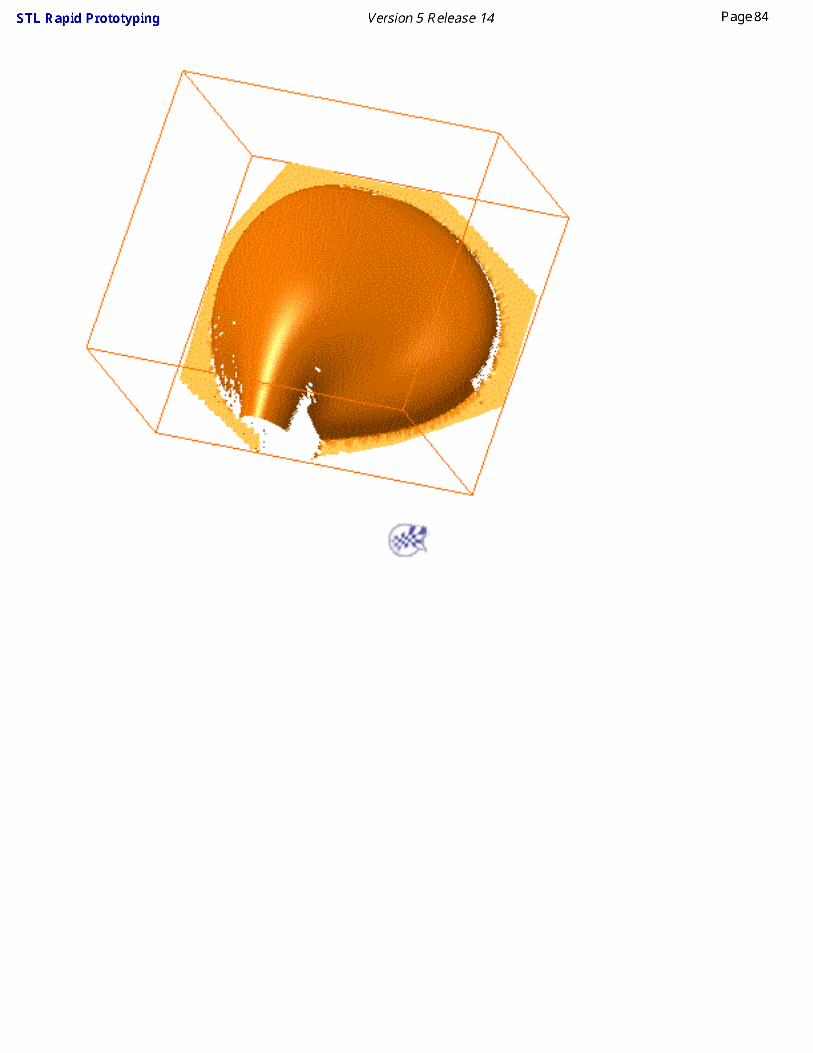
The final cloud element will look like this:

Creating a Basic Surface Tessellation
The first task will show you how to enter the STL Rapid Prototyping workbench and create a basic surface tessellation.
The only pre-requisites for this task is to have a current session running.
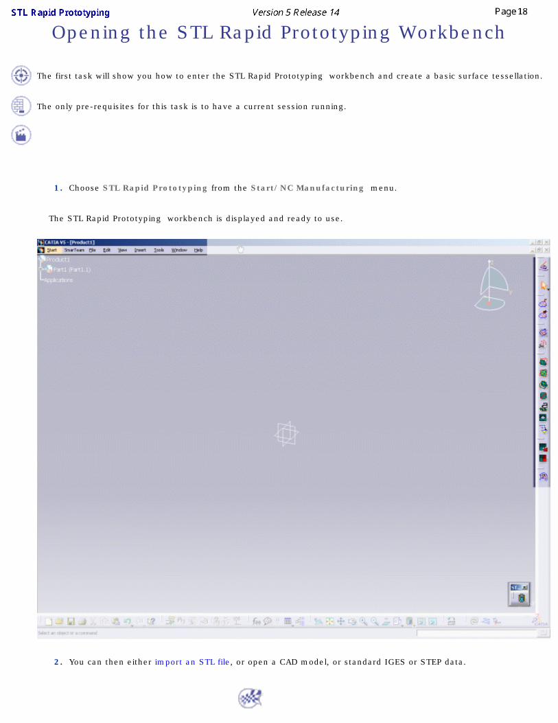
1. Choose STL Rapid Prototyping from the Start/NC Manufacturing menu.
The STL Rapid Prototyping workbench is displayed and ready to use.
2. Open the GettingStartedSTL.CATPart from the samples directory. It is a hairdryer, made of surfaces, with a gap
and a hole in it.

3. Click the Surface Tessellate icon and select the hairdryer. Click Apply and OK.
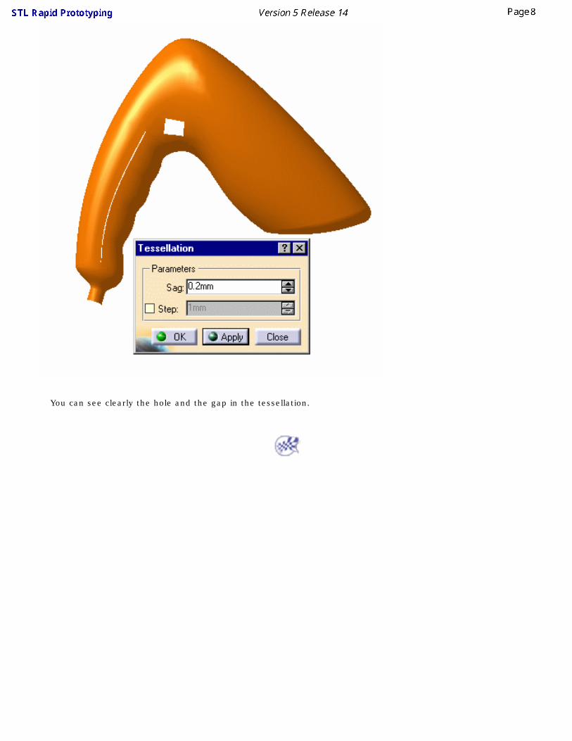
You can see clearly the hole and the gap in the tessellation.

Repairing the Mesh
This task will show you how to repair a mesh.
Use the mesh you have created in the previous task.
Repairing the hole:
1. Click the Fill Holes icon and select the mesh.
The exterior edge of the model is displayed in red, with an "x" meaning this edge is not candidate for a filling.
The two other edges in green with a "v" surround holes candidates for the filling.
2. Place the cursor over the label of the long hole and call the contextual menu. Choose Not selected.

3. Click Apply and OK. The hole is filled:
Repairing the gap:
1. Click the Define a Mesh Area icon and select the mesh (Tessellation.1).
2. Draw a trap around the gap and check the Inside Trap option.

Click Apply and OK. A portion of the mesh is activated:
3. Click the Mesh Regeneration icon and select the mesh (Tessellation.1). Check the Constrained option.
Click Apply and OK. A MeshCreation.1 element is created in the specification tree: the mesh on this portion has been regenerated.

4. Select the Tessellation.1 element in the specification tree and click the Activation icon. Push the Activate All button. Both meshes are
now active (we have changed MeshCreation.1 to pink). From the picture below you can see that they are complementary:

5. Click the Merge icon and select the two meshes:
6. Click OK. A Meshes Merge.1 element is created in the specification tree. You have now a flawless mesh.

Checking the Mesh Quality
This task will show you how to quickly check the quality of the mesh.
Use the mesh you have created in the previous task.
1. Click the Display icon and select the Meshes Merge.1 mesh. The Cloud Display Options
dialog box is displayed.
The default option is Smooth. You can check :
● the Triangles option:
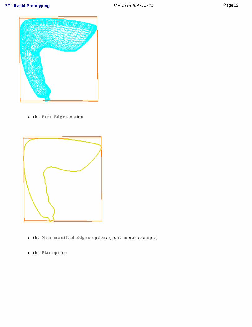
● the Free Edges option:
● the Non-manifold Edges option: (none in our example)
● the Flat option:

You can combine all of them too.

User Tasks
Starting the STL Rapid Prototyping WorkbenchUsing the Keyboard
STL filesSTL EditionSTL Mesh
STL OperationsDisplay Options
InformationInteroperability
Managing Geometrical Sets
Opening the STL Rapid Prototyping Workbench
The first task will show you how to enter the STL Rapid Prototyping workbench and create a basic surface tessellation.
The only pre-requisites for this task is to have a current session running.
1. Choose STL Rapid Prototyping from the Start/NC Manufacturing menu.
The STL Rapid Prototyping workbench is displayed and ready to use.
2. You can then either import an STL file, or open a CAD model, or standard IGES or STEP data.

Using the Keyboard
Key Command Action
ShiftActivationRemove (Pick or Brush), Split
Deselects selected elements

STL FilesThese actions deal with the import and the export of files

Importing Files
This task shows how to import digit files describing a cloud of points (scanned or computed) or a mesh.
Use the MultiImport1.cgo_ascii, MultiImport2.cgo_ascii, MultiImport3.cgo_ascii from the samples directory.
Available formats depend on the workbench you are working in.
Digitized Shape Editor ● Ascii free,
● Atos (the quality of the points can be taken into account),
● Cgo,
● Gom-3d (as points, scans, grids or meshes, the quality of the points can be taken into account),
● Hyscan,
● IGES (IGES Entities 116 are processed. If the cloud to import is made of Entities 116 only, the result is a cloud of points. Otherwise, the
result is made of scans).
● Kreon
● Steinbichler (as points, grids or scans),
● Stl (bin or ascii, with creation of free edges and facets, if requested).
STL Rapid Prototyping ● STL files (bin or ascii, with creation of free edges and facets, if requested) (default option),
● Cgo,
● Ascii free,
● IGES (IGES Entities 116 are processed. If the cloud to import is made of Entities 116 only, the result is a cloud of points. Otherwise, the
result is made of scans).
● In Cgo, Ascii and IGES formats, you can not process more than 10,000 points at each import, in one or several files, e.g. you can not import 4 files of 3,000 points each in one shot but you can import them separately.
● This limitation applies to the input files (before Sampling or resizing with the bounding box).
● If you try to import over 10,000 points in one shot, a fatal error panel is displayed: Too many points for this configuration.❍ If the Grouped option is active, no file is imported.
❍ If the Grouped option is not active, files are imported as long as the sum of their points does not exceed 10,000 points.
● Mesh Regeneration is not available on those files.

Shape Sculptor● STL files (bin or ascii, with creation of free edges and facets, if requested).
1. Click the Import icon . The Cloud Import dialog box is displayed.
2. In the Format field, select the file format.
3. In the Selected File area, use the button ... to browse your directories and select a file.
4. Check the box Statistics to display information about the model you are importing. If you want to import several files in one shot,
please refer to the Grouped explanations.
5. In the Options field:
● Enter the Sampling percentage to apply;
The sampling value determines the percentage of points or scans or grids that will be read from the digit file.
● Enter the Scale factor to apply to the model, as well as the Unit used in the file.
● If the extension of the file you have selected is consistent with the list proposed, the Format field is updated automatically. Otherwise, be careful to enter the correct format in that field.
● Once you have performed an import operation, V5 proposes the last entered file path and format as default. If you click on ..., the last entered directory is proposed as default.
● The File unit option is not relevant to the Steinbichler format, nor the Sampling percentage to the Stl format.
6. For some digit file formats, you may want to enter additional data that are displayed by clicking the button More>>

For Ascii: For Atos and Gom-3d: For Iges: For Stl:
Direction and Delimitors apply to scans. Enter these data whenever you know them.
Minimal Point Quality is used to clean Atos file from invalid points. The quality value of a point lies between 0 and 255 (low to high). Choose a value to ignore points below that value:
● Minimal Point Quality value is 125:
● Minimal Point Quality value is 75:
System applies to the operating system (Unix or Windows NT) used to generate the binary data: select Same if you know you are using the same operating system as the one used to generate the binary data, Other for the other way, Unknown if you have no indication.
Free Edges is used to create or not the scans representing the free edges of a mesh:
or Facets is used to create or not the facets of the imported mesh:
or

7. Click Apply to display the cloud of points or mesh:
8. Push the button Update to display the bounding box of the cloud of points or mesh. Use the green arrow to resize it in order to import
only a part of the cloud of points or mesh.
● The bounding box appears every time the cursor passes over a cloud of points or a mesh. Its size corresponds to that of the visible points.
● If a local axis system is set as current, the file will imported in this axis systems and not in the absolute axis system as previously. If no local axis system is set as current, the file will be imported in the absolute axis system.
● Moreover, if a local axis system is set as current, the axis system of the dynamic box used to select a portion of the imported file when the Update button is pushed is parallel to the local axis system axis.
The check box Replace is used to replace the current cloud of points or mesh by a new one.

9. Once you are satisfied with the preview, click Apply and OK to finish the import of the cloud of points or mesh.
● The name of the element created in the specification tree is the name of the original file, without its extension.
● Undo and Redo are available.
● V5 memorizes the data of the last imported file and proposes them at the next import action.
Importing a Set of Files
1. Click the Import icon . The Could Import dialog box is displayed. The operating mode is the same as for one file.
The files to import must: ● have the same format,
● be located under the same directory.
The Selected File field looks like this: If you check the Grouped option (this is the default status):
All the files are imported as one single cloud of points instead of several:
If you do not check the Grouped option:
The files are imported separately.

The three digit files have been imported together, resulting in one cloud of points or mesh.
The three digit files have been imported separately, resulting in three clouds of points.
One cloud of points Element Cloud Import.x is created in the specification tree, with the icon of the Import command.
One cloud of points element is created in the specification for each input file, with the icon of the Import command and the name of the input file (MultiImport1.1, MultiImport2.1, MultiImport3.1) .
● You can also merge several clouds of points into one whenever necessary, using the Merge Clouds command.

Exporting Polygons to STL
This task shows how to export a mesh to binary Stl format.
Other formats available are:
● ASCII,
● cgo.
Open the Cloud.CATPart from the samples directory.
1. Select the Polygon.1 and then the export icon .
The export dialog box is displayed.
2. One export format is available: Stl.
3. Browse your directories and enter the target directory and file name. Then click Save.
● The selection is exported with the current local axis system if any, with the absolute axis system otherwise.

● You can export only one element at a time.
● In STL Rapid Prototyping, only the Stl format is available.

Editing Meshes
This chapter deals with the edition of meshes, i.e. Selection, Remove actions.
Although the dialog boxes look similar, the operating mode of the Select and Remove actions are slightly different:
● De-activated triangles can be recalled using Activate all and Invert in a new activation action.
● Removed triangles can not be recalled! Activate all and Invert apply only to the current removal action. They can not be used to recall removed triangles, once you have clicked OK.
● The Activation action displays only triangles that are fully selected (i.e. the whole triangle is inside the selection trap, or all its vertices have been picked). If you select only one or two vertices of a triangle, or if the selection trap intersects the triangle, it is not displayed.
● As a consequence, when you push the button Swap, the triangles displayed are not the exact complement of the previous selection.
● The Remove action takes into account triangles that are at least partially selected (at least one vertex has been picked, or the selection trap intersects the triangle).
Activating a Portion of a CloudRemove

Activating a Portion of a Cloud of PointsThis task shows how to select a portion of a cloud of points or of mesh in order to create a work area, either:
● by picking directly elements of the cloud (points, scans, grids, cells, clouds) or
● by defining a portion of the cloud or mesh with a 2D or 3D trap,
● by moving a brush over a portion of a mesh.
The free edges displayed are those of the complete mesh: ● if you activate only a portion of a mesh, the free edges of that portion are not displayed.
Open the Cloud.CATPart model the from the samples directory.
Click here for more information on the dialog box.
1. Click the Activate Areas icon and the mesh. The Activate dialog box is displayed.

2. Draw a rectangle by dragging the mouse over the portion you want to select.
As you release the mouse, the triangles selected are highlighted in red. When you move the mouse over one corner of the rectangle, dimensioning arrows are displayed, enabling you to resize the rectangle.

3. Push the Valid Trap button that is now available and draw a second rectangle. Push Valid Trap
again.
4. Push the Swap button. The selection is inverted.

5. Click OK to validate and exit the action.

Removing Elements
This task shows you how to remove a elements from a cloud or a mesh.
● The deleted elements are those that appear in red during selection.
● By default, the trap is displayed in the view plane (2D trap). You can rotate the model to display the trap as a 3D trap.
● Within one removal action, use Activate all to recall all the points of the original cloud of points, or Swap to invert the selection (the complement of the current selection becomes active whereas the current selection is hidden).
● The Remove action takes into account triangles that are at least partially selected (at least one vertex has been picked, or the selection trap intersects the triangle).
● Undo/Redo are not available on the global action.
● Although the dialog boxes look similar, the operation mode of the Select and the Remove actions are slightly different:
● Removed elements can not be recalled !
● Activate all and Swap apply only to the current removal action. They can not be used to recall removed elements once you have validated the action.
● All free edges may be displayed.
Open the Cloud.CATPart model from the samples directory.
Click here for more information on the dialog box.
1. Click the Remove icon and the mesh. The Remove dialog box is displayed.
2. Check the Pick option, then the required element type (Level) to remove elements using the hierarchical selection.
According to your choice and the application you are working in, only points, or triangles, or scan/grid, or cells (sub-

cloud) or clouds (global cloud) will be removed. Select the unwanted elements on the cloud, then Click OK to confirm
their removal and close the dialog box.
Or check the Trap option then the required Trap Type and the portion of cloud to remove (Inside or Outside Trap)
to remove elements using a graphical trap. You can draw either one single trap, or several traps.
In that case, valid each trap with the Valid Trap push button before drawing the next one.
If you draw a trap, push Valid Trap, then Swap, you will remove the complement of the original selection.
Click OK when all traps have been defined to remove the unwanted elements and close the dialog box.
The traps may be either rectangular :

In that case, you can modify the trap using the green manipulators.
or polygonal :
or spline:

In those cases, you can modify the trap using the green manipulators or use the Undo action on each segment of
the trap as long as you have not double-clicked to end the polygonal trap.

Mesh
This chapter deals with the tessellation of clouds of points.
Mesh CreationSurface Tessellation
OffsetFlip Edges
Smoothing MeshesMesh Cleaner
Fill HolesInteractive Triangle Creation
Decimating MeshesOptimizing Meshes

Mesh Creation
This task shows how to mesh a cloud of points or regenerate an existing mesh.
The Mesh Creation and the Mesh Regeneration actions offer:
● a neighborhood parameter that makes it possible to fill holes or to let some areas unmeshed,
● an automatic detection or a manual definition of the meshing plane for the 2D mesher,
● boundary continuity with contiguous meshes through the Constrained option,
● a fully automatic 3D meshing (c)INRIA, suitable for mechanical parts with blind or through holes, that respects details, especially sharp edges,
● a sag value to mesh dense clouds with a reduced number of triangles, but still respecting the 3D Shape within a given tolerance.
In STL Rapid Prototyping, Mesh Regeneration is allowed on meshes only, i.e. objects whose partially or totally active cells are meshes.
If this is not the case, a fatal error panel is displayed: Mesh Regeneration is allowed on meshes only.
Open the Cloud.CATPart model from the samples directory.
1. Click the Mesh Creation or Mesh Regeneration icon . The Mesh Creation dialog box is
displayed.
2. Check the Execution Mode option you need:
● 3D (c)INRIA: this is a meshing method for complicated shapes (e.g. mechanical objects, clouds that can not be projected onto a single plane, or without draft characteristics).
This is the default option.
● 2D: this is a less complex meshing method, to apply to simple objects, i.e. that can be projected onto a single plane (smooth shapes).
The entry dialog box is replaced with that of the 2D Mesher.

This mesher provides a Sag option to reduce the number of triangles computed on dense clouds. However, this option respects the shape of the object.
You would achieve the same result by filtering the cloud with the adaptative option set to the sag value and meshing the output.
You can also mesh a cloud with a sag equal to 0. This means that all the points are meshed. This algorithm is more suitable to mesh large clouds quickly.
3. If necessary check the sag option and enter
its value, or keep the default 3D Mesher.
3. Select the plane that is the computation
reference for the meshing:
❍ either one main plane
❍ or one defined with the compass
The quality of the mesh depends on the
computation direction.
4. A Neighborhood value is proposed in accordance with the model. This value represents the
maximal edge length of the triangles displayed. The value proposed is just an approximation of
this value. Its relevance depends on the distribution of the points in the cloud. It is visualized by a
sphere. You can change its position by a simple mouse click.

The sphere is updated when you change the Neighborhood value.
5. Check the Display option you need:
● Triangles to display only the mesh,
● Shading to simulate the surface of the object: ❍ with the Flat option, the light is sent on the triangles along their normal,
❍ with the Smooth option, the light is smoothed over the triangles, giving a better image of the quality of the surface.

● Meshing requires a complex computation. The computation time will increase according to the size and complexity of your model. You may want to filter the cloud before starting the meshing.
● To mesh large quantities of points, we recommend the following settings:❍ Sag=0mm
❍ Triangles not activated
❍ Shading activated, with the Smooth option.
These display options are applied within this action only. Once you have validated the result with OK, the result is displayed in the Smooth mode, even if the input element or the computed mesh were displayed in another mode.
6. Constrained is used to:
● re-process a portion of a mesh by adding points to an existing mesh or reprocessing a meshed cloud that has been unfiltered::

Open the Mesh2.CATPart model from the from the Samples directory.
The original mesh had holes in it. Select a faulty portion and proceed to a new meshing on that portion.
The original mesh is in red. The re-processed mesh is in blue.
● connect several meshes:Open the Mesh1.CATPart model from the Samples directory. Draw two traps on that part and mesh them with different values, as shown below. Now activate the remaining square of points, as shown below.
For quicker meshing performances, you can filter portions of the parts according to your successive needs.
The mesh is unconstrained, the activation trap does not overlap the previous meshes. The resulting mesh is independent from the other two.
The mesh is constrained, the activation trap overlaps the previous meshes. The resulting mesh is connected to the other two. Facets of the existing mesh that were totally or partially inside the trap have been removed and recomputed to adjust to the additional mesh.

7. Click Apply to check or update the result. Then click OK to confirm the result and exit the action.
An element Mesh Creation.x is created in the specification tree.
Increase the Neighborhood value to improve the mesh or reduce it to avoid filling holes that should remain clear:
Triangles:

Shading:
● In some cases, it may be difficult to find a Neighborhood value that will fill unwanted holes, without creating unwanted triangles:
● Seams may appear on the mesh with the Smooth option, :
● They indicate that the normals to the facets have different directions at this place.
● In 2D and 3D mode, some triangles may overlap and mesh should be corrected.
● In Constrained mode, they show the common boundaries of meshes.
● When computing a constrained mesh, enter 0 as the Neighborhood value to check the boundaries of the mesh. If the boundaries are not satisfactory, modify the mesh plane to improve them.
● After the computation of a constrained mesh, two mesh elements are visible in the specification tree: the constrained mesh and the initial mesh. You can select one and then the other to make sure they are complementary.
● You can use the Meshes Merge action to obtain a single mesh.

Tessellating an Object
This task shows how to create a tessellation from a surface or a solid. Inside this action, you may specify the maximum size of the triangles and the maximum distance (sag) between the geometry and the triangles.
Open the SurfTessellation1.CATPart model from the samples directory.
1. Click the Surface Tessellation icon . The Tessellation dialog box is displayed.
2. Select the surface or the solid to tessellate. Clik Apply.

3. You can modify the Sag value, that is the maximum distance between the geometry and the
triangles:
it has been increased to 1
4. You can also check the Step box to control the length of triangles:

5. Click OK to validate. A Tesselation.x element is created in the specification tree.
● The free edges of the tessellation are those of the surfaces or solids.
● To avoid free edges between the tessellations of several contiguous faces, you can join them with the Join action of Quick Surface Reconstruction or Generative Shape Design. They will then be processed as a single surface.

Offsetting a Mesh
This task shows how to offset a mesh and create a watertight mesh.
Open the Offset1.CATPart model from the samples directory.
1. Select the Offset icon . The Offset Mesh dialog box is displayed.
2. Select the mesh.
3. Enter an Offset value. The offset mesh is displayed, together with a green vector representing
the offset. The direction of the offset is given by the sign of the value.

4. Check the Create shell option to create a watertight offset::
Create shell unchecked Create Shell checked
5. Click Apply to check or update the result. Then click OK to confirm the result and exit the
action. The element Mesh Offset.x is created in the specification tree.

● The offset is computed in the direction of the weighted normals of the points.
● For better results, you should avoid to enter a high offset value.

Flip Edges
This task shows you how to flip edges of triangles of a mesh, for a better respect of sharp edges, by rotating the triangles common edges without modifying their vertices. The meshing may become less harmonious but will provide a better respect of the shape of the part because the triangles will be oriented in the direction of the shape, in particular for sharp edge fillets. This is particularly important for milling operations that may follow.
This action reorganizes the meshing without modifying the geometry because the vertices are not recomputed.
The first picture shows a blunted edge.
The second picture shows the same edge after the reorientation of the triangles.
Open the Cloud.CATPart model the from the samples directory. For a better understanding, use the Cloud Display Options icon to display the triangles of the mesh.
1. Click the Flip Edges icon and a mesh. The dialog box is displayed.
2. Sets the value of Depth, that determines the amplitude of the reorganization of the mesh:
● The value of Depth ranges from 0 to 10.
● The default value is 2.
● When the value of Depth is 0, the action processes a triangle and its direct neighbors.

● When the value of Depth is 1, the action processes a triangle, its direct neighbors and
their direct neighbors, and so on as you increase the value of Depth.
● This may lead to a temporary degradation of the energy function of the mesh, but results
in a final optimal solution.
● The computation time depends on the value of Depth, and on the size of the mesh to
process.
3. Click Apply to start the first reorganization iteration. Click Apply again to start another iteration.
You may repeat this step as many times as you wish.
4. Click OK to validate the result. A Flip_Edge.x element is created in the specification tree. The
initial mesh is sent to the No Show.
● The new mesh inherits the graphic properties and display mode of the initial mesh.
● During the process, the mesh is displayed in Flat Shading mode.
● This action should not be used on meshes with non-manifold edges.
● Undo/Redo are available.
● You may create several Flip_Edge.x elements in the specification tree, corresponding to various degrees of reorganization of a given mesh. You may then delete any of them, according to your needs.

Smoothing MeshesThis task shows you how to smooth a mesh.
The cloud of points you import in Digitized Shape Editor may be noisy, for various reasons, mainly because of a poor digitalization accuracy on the edges of parts. This noise is found again on the meshes computed from these clouds of points or imported in STL format.
The consequences are:
● very noisy scans produced with the Planar Sections or Segmentations actions or
● the reconstruction of wavy curves or surfaces and/or of very high order.
This can be partly avoided by smoothing the mesh.
● Since the volume of the part is reduced, some small facets may be inverted by the meshing. Therefore we recommend you alternate Mesh Smoothing and Flip Edges actions.
● Use the Activate function to process only a portion of a cloud.
Open the SmoothMesh01.CATPart from the samples directory
1. Click the Mesh Smoothing icon and a mesh.
2. The Smoothing dialog box is displayed.

3. Select the type of smoothing:
Choose Single effect if there is no sharp edge on the mesh to process.
● Small radii will be erased.
● The volume of the part will be reduced (contraction towards the center of gravity of the part).
Choose Dual effect to reduce the distance between outliers and the surface, and reduce the erasing of small radii.
● The reduction of the volume of the part is smaller.
● A large displacement of one vertex inwards may cause the neighboring vertices to move outwards.
4. Two other controls are available:
● Coefficient : It balances the effect of the new theoretical position in comparison with the original position. It varies from 0 (the vertex is not moved) to 1 (the vertex is moved to the computed position).
● Max Deviation: Check this option to control the maximum deviation allowed (the displacement will remain under the value set.)
● The deviation is the distance between a vertex and its initial position (not between its current position and that of the previous iteration).
● Therefore, if you want to control the maximum deviation, you have to check the Max Deviation option before the first Apply (it is no longer available after the first Apply).
● For a better appreciation of the quality of the intermediate meshes, the meshes are displayed in Flat Shading within the action.
● In addition, for each step the maximum and the mean deviations (distances between a vertex and its initial position) are displayed in the dialog box.

5. Click Apply: a new mesh is computed. This action is an iterative one: click Apply again to smooth
the proposed mesh.
6. Click OK once you are satisfied. A Smoothing.x element is created in the specification tree, the
original mesh is sent to the No Show.
Examples: Original part, before entering the action, i.e. in Smooth Shading:

Original part as you enter the action, i.e. in Flat Shading:
Single effect, in Flat Shading

Single effect, in Smooth Shading (after exiting the action)

Dual effect, in Flat Shading
Dual effect, in Smooth Shading (after exiting the action)

Mesh Cleaner
This task will show you how to clean a mesh.
Imported STL files or generated meshes may present some irregularities such as:
● Corrupted triangles, i.e. triangles that have the same vertex twice,
● Duplicated triangles, i.e. triangles that share the same three vertices,
● Inconsistent Orientation, i.e. triangles that can not be oriented consistently with respect to each other,
● Non-manifold edges, i.e. edges shared by more than two triangles,
● Non-manifold vertices, i.e. vertices shared by two or more connected shells.
A mesh may also present some structural problems such as:
● Orientation problems, i.e. all the triangles are not oriented in the same direction,
● Isolated triangles, i.e. triangles belonging to small connected areas of the mesh,
● Disconnected zones, i.e. the mesh is made of several disconnected zones,

● Triangles with long edges.
Mesh cleaner proposes two families of treatments on such meshes:
● Deletion, i.e. visualization and deletion of corrupted or duplicated triangles, of triangles with an inconsistent orientation, of non-manifold edges, or non-manifold vertices, of isolated triangles and triangles with long edges.
● Structure, i.e. e-orientation or split.
You can process simultaneously several types of problems in the Deletion tab. Structure problems must be processed separately.
Open MeshCleaner1.CATPart the from the samples directory.

1. Click the Mesh Cleaner icon and select the mesh to process. The dialog box is displayed.
2. Go to the tab of the treatment you want to apply.
In the Deletion tab:
3. Push the Analyze button.
Once the analysis is completed, the line(s) corresponding to the problem(s) found become
active. The Statistics column is updated with the number of cases found for the four first lines.
Here, only non-manifold vertices have been found, and there are 5 such vertices.

4. You can visualize the problems found:
● Check the line(s) of the problem you want to visualize. By default, they are displayed in
white. You can choose another color in the Preview colors combo box.
5. For Isolated Triangles, use the slider to define the maximum number of triangles that a
disconnected area may contain. If you set the slider to n, all the areas containing between 1 and n
triangles will be visualized, then deleted. The limit values of the slider are defined according to the
mesh.
For Long Edges, use the spinner to define the maximum allowed length edge of triangles. All
triangles with edges longer than this value will be deleted.
6. Click Apply to delete the unwanted elements and OK to exit the action and save the processed
part.
In the Structure tab:

1. Check the Orientation line and click Apply to re-orient triangles, if that is possible.
or
1. Check the Split in Connected Zones. The text box below is updated with the number of
connected zones found. You can then choose to split them in Distinct zones or in one Grouped
zone by checking the appropriate option and clicking Apply. SubMesh.x elements are then
created in the specification tree.
2. Click OK to exit the action and save the processed part.

Filling Holes on Meshes
This task shows you how to fill holes on meshs with the following advantages: ● You can either select the holes manually or automatically.
● The filling can be basic (no point inserted, basic remeshing) or more sophisticated (points are inserted, and the meshing can be flat or curved).
Open the Fillhole1.CATPart from the samples directory.
1. Select the Fill Holes icon and Cloud Import.1.
2. The dialog box is displayed. A first recognition of the holes is done:
● X means the hole is not selected,
● V means the hole is selected,
● The biggest hole found is considered as "exterior". Since you usually do not want to fill the outside of the part, this hole is not selected, but you can change its status.
3. Click on the label to select or de-select a given hole or right-click on a label to call the contextual
menu:

Use Selected/Not selected as a toggle on a single hole, and Select all/De-Select all as a toggle
on all holes.
4. If you want to select the holes to fill automatically, check the Hole size option. A sphere is
displayed. You can change its diameter in the box on the right:
● either enter a value,
● or right-click to call the contextual menu:
All the holes smaller than this sphere are selected.
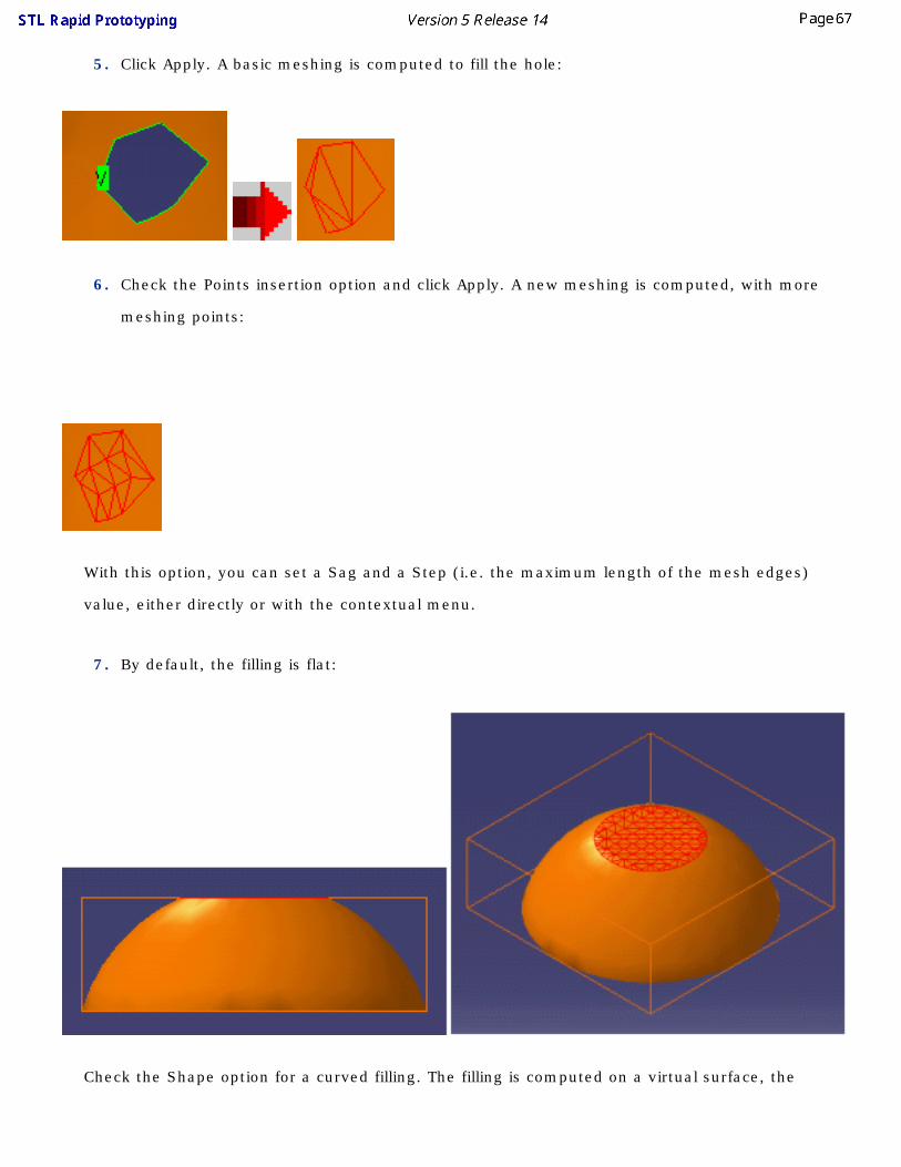
5. Click Apply. A basic meshing is computed to fill the hole:
6. Check the Points insertion option and click Apply. A new meshing is computed, with more
meshing points:
With this option, you can set a Sag and a Step (i.e. the maximum length of the mesh edges)
value, either directly or with the contextual menu.
7. By default, the filling is flat:
Check the Shape option for a curved filling. The filling is computed on a virtual surface, the

curvature coefficient of which is controlled by the slider on the right: increase this coefficient to
increase the curvature of the filling.
8. Click Apply to visualize the filling with given parameters. If you are not satisfied, click Undo,
modify the parameters and click Apply to refresh the filling. Once you are satisfied, click OK to
validate and exit the action
● Undo is available within the action, not after you have exited the action.
● The holes to fill must be closed.
● When no coherent result can be computed, an error message is displayed.

Interactive Triangle CreationThis task will show you how to create mesh triangles interactively:
● to create or modify a mesh quickly or
● to simplify hole filing by creating bridges within a hole.
Open the Fillhole1.CATPart from the samples directory.
1. Click the Interactive Triangle Creation icon . The Interactive Triangle Creation dialog box is
displayed.
2. To create a new mesh triangle, you can input:
● three points (vertices of an existing mesh or not), or
● two neighboring edges of a mesh (with a vertex in common), or
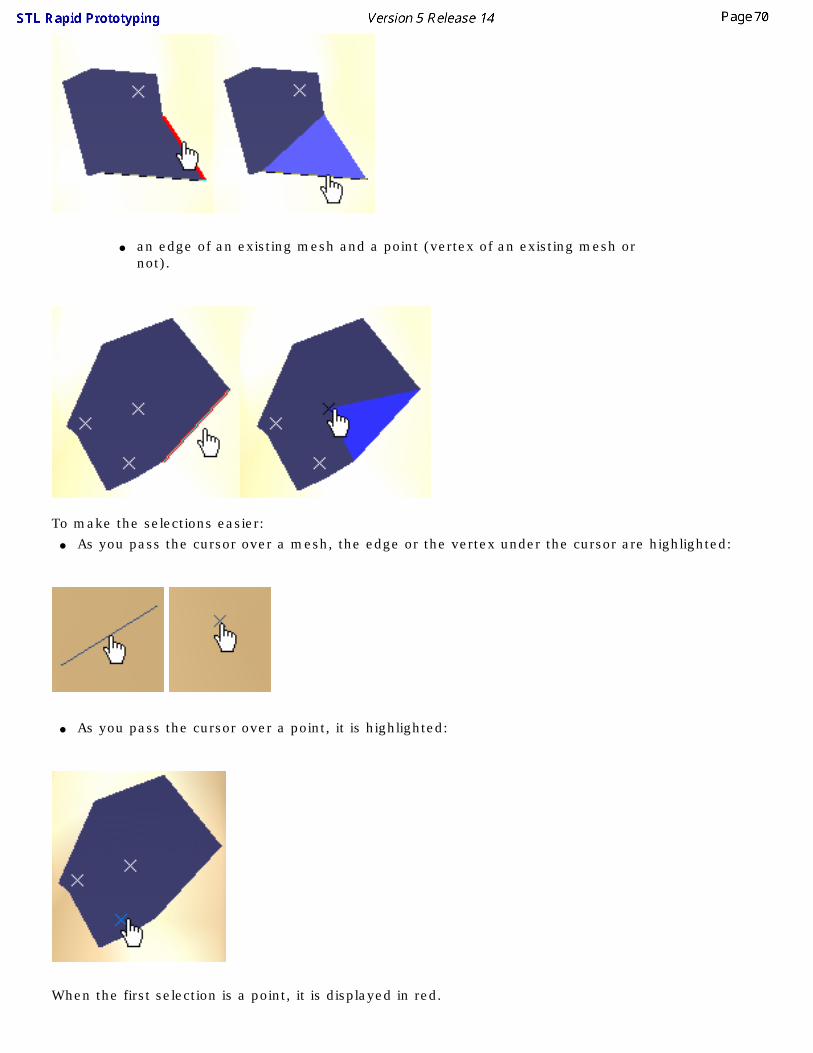
● an edge of an existing mesh and a point (vertex of an existing mesh or not).
To make the selections easier:
● As you pass the cursor over a mesh, the edge or the vertex under the cursor are highlighted:
● As you pass the cursor over a point, it is highlighted:
When the first selection is a point, it is displayed in red.

● If the next selection is another point, a red line is displayed between those two points. At the next point selection, a triangle is proposed and displayed in blue.
● If the next selection is an edge, a triangle is proposed and displayed in blue.
When the first selection is an edge, it is displayed in red. At the next selection, a triangle is proposed and displayed in blue.
3. Once a triangle is proposed:
● you can select other elements to define more triangles. They will be proposed and displayed in blue, or
● click Apply. The triangle(s) displayed in blue is(are) created temporarily. You can create further triangles.
4. Click OK to validate the creation of triangles:
● if the first element picked was a point that did not belong to a mesh, a
new Mesh.x element is created (even if the other elements selected
belong to a mesh),
● if the first element picked was a vertex or an edge of an existing mesh,
this mesh is modified and no other mesh is created.
or Cancel to exit the action without creating any triangles.
The first element picked is Point.2. A new mesh is created.

The first element picked is an edge of Cloud Import.1. Cloud Import.1 is modified, no new mesh is created.
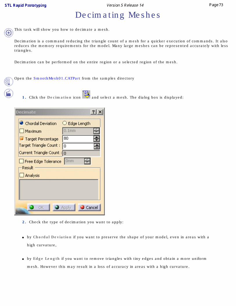
Decimating MeshesThis task will show you how to decimate a mesh.
Decimation is a command reducing the triangle count of a mesh for a quicker execution of commands. It also reduces the memory requirements for the model. Many large meshes can be represented accurately with less triangles.
Decimation can be performed on the entire region or a selected region of the mesh.
Open the SmoothMesh01.CATPart from the samples directory
1. Click the Decimation icon and select a mesh. The dialog box is displayed:
2. Check the type of decimation you want to apply:
● by Chordal Deviation if you want to preserve the shape of your model, even in areas with a
high curvature,
● by Edge Length if you want to remove triangles with tiny edges and obtain a more uniform
mesh. However this may result in a loss of accuracy in areas with a high curvature.

3. Then, decide how you want the decimation to stop:
● For a decimation by Chordal Deviation, you can check Maximum and enter a value. It is the
chordal deviation that should not be exceeded during decimation. Decimation stops when the
chordal deviation limit has been reached.
● For a decimation by Edge Length, you can check Minimum and enter a value. The command
stops when further decimation could collapse edges of length greater than the value entered.
● For both types of decimation, check Target Percentage if you want to obtain a given final
number or percentage of triangles. Enter either the percentage value or the Target Triangle
Count. Those fields are linked to each other and updated simultaneously.
Current Triangle Count indicates the current number of triangles, either of the original model when
you enter the action, or of the result model when you have clicked Apply.


4. You may need to control the decimation of free edges, when a rectangular shape sees its corners cut off
after decimation. You can avoid this by checking Free Edge Deviation. This activates the maximum
allowable deviation that can occur for vertices on the boundary. The resulting decimated boundary will
not be at a distance greater than this parameter from the original boundary.

5. The chordal deviation that can be used as a stopping criterion is an approximation of the chordal
deviation between the original mesh prior to decimation and the decimated mesh. Therefore it may be
useful to know the maximum distance and the mean distance between the original mesh and the result
mesh at the end of the command.
To do so, check Analysis before clicking Apply. At the end of the decimation, the maximum and the mean
deviation will be reported as shown below. Unlike the value entered in the Maximum field, they are the true
deviations between the original mesh and the result mesh.
● However, Analysis may be time consuming, especially for large models. we recommend that you turn it off when you do not need it.
● The meshes can be decimated in several steps (click Apply= one step). The deviations displayed are those between the original model and the last result (not those between the previous and the current results). For this reason, the deviations will be increasing in value after each Apply.
● Any selection change resets the original model for the analysis.
● Undo is not taken into account by the Analysis.

At each Apply, a progress bar is displayed. A Cancel button is available to stop the decimation.
6. Click OK to confirm the decimation once you are satisfied with the result.

Optimizing MeshesThis task will show you how to optimize an existing mesh, i.e. redistribute and reshape the triangles within the mesh. This way you will obtain a more homogeneous mesh, e.g. for analysis purpose.
● Be aware that this optimization tends to modify the shape of the model!
● Non-manifold meshes can not be processed. You should use the Mesh Cleaner.
● Mesh Optimize is an iterative operator using edge splits and edge collapses. If an edge is too long, it is split in two. If an edge is too short it is collapsed. Consequently, there is a minimum ratio between the minimum and maximum edge length; otherwise an edge that has just been split could be collapsed at the next step and then split again and so on.
Open the SmoothMesh01.CATPart from the samples directory. You may want to display the triangles of the mesh, using the Cloud Display command.
1. Click the Optimize icon and select the mesh.
2. Set the Minimum Length, Maximum Length and Dihedral Angle according to your needs.

● Minimum Length and Maximum Length refer to the length of the edges of the triangles.
● The Minimum Length must be less than or equal to the half of the Maximum Length.
● Dihedral Angle is the angle between two triangles.
● All the triangles with edges shorter than the Minimum Length will be collapsed so that their edges reach this Minimum Length.
● All the triangles with edges larger than the Maximum Length will be refined so that their edges reach this Maximum Length.
● Al the triangles with an Dihedral Angle lower than the value given will be flipped.
● Make sure the chosen values are coherent with your model.
3. Check the Analysis option to display the maximum and the mean deviations (distances between a
vertex and its initial position) in the dialog box.
4. Click Apply.
5. Click OK to validate the optimization and modify the initial mesh, or Cancel to exit the action without
any modification.

Operations
This chapter deals with the operations on meshes.
Meshes MergeSplit
Trimming or Splitting a Mesh

Merging Meshes
This task shows how to merge two meshes. This action is useful especially for meshes resulting from a constrained mesh: it removes the seam created by the constrained mesh.
This action does not modify the triangles of the meshes (holes are not filled, no management of overlaps, ...). For a good result, repair the meshes first, using constrained meshing, fill hole action, ....
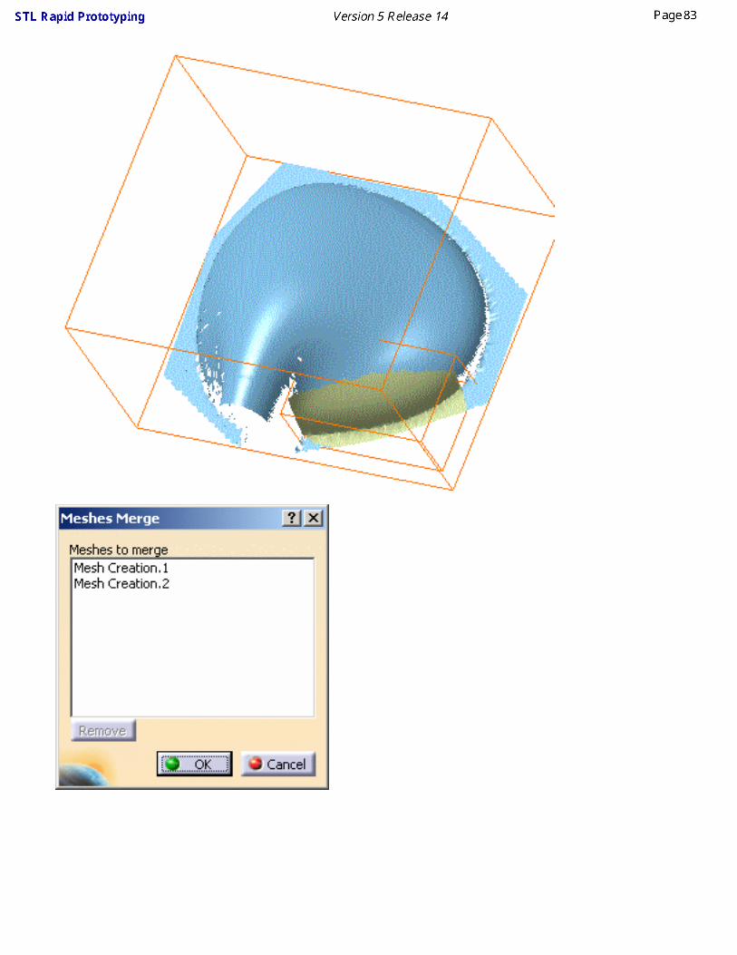
Open the MergeMeshes1.CATPart model from the samples directory. It consists of two meshes, the smallest resulting from a constrained meshing.
1. Select the Merge Meshes icon . The Meshes Merge dialog box is displayed.
2. Select the meshes you want to merge. The list in the dialog box is updated.
3. To remove a mesh from the list of meshes to merge, make its name active in the list and check
Remove.
4. To replace a mesh in the list of meshes to merge, remove it, then select a new mesh.
5. Once you have selected all meshes to be merged, click OK. A new single-cell mesh is created in
the specification tree under the name Meshes Merge.x.

Splitting Meshes
This task shows how to split a mesh or a cloud.
Open the Cloud.CATPart model the from the samples directory.
Click here for more information on the dialog box.
1. Select the Split icon . The Split dialog box is displayed.
2. Select the mesh or the cloud to split.
3. Select a portion of the element according to the Activation operating mode.
4. Once the selection is done, click OK to validate.
5. The input element is hidden. Two elements are created in the specification tree:
● SplitCloud.1 and SplitCloud.2 if you the input element was a cloud. SplitCloud.1
corresponds to the remaining portion of the original cloud, SplitCloud.2 is the split cloud
(portion selected).
● SplitMesh.1 and SplitMesh.2 if you the input element was a mesh SplitMesh.1
corresponds to the remaining portion of the original mesh, SplitMesh.2 is the split mesh
(portion selected).
● The output element indexes are increased if further splits occur.

● If the selection is empty, or if the whole input element is selected, no split element is created.
● To retrieve the original input element, recall it from the No Show, or merge the two split elements.
● When you split a mesh using the Trap option, the triangles are smoothly cut by the trap line.


Trim/Split This task will show you how:
● to split a mesh in several meshes (displayed in different colors below):
● and/or trim portions of the mesh delimited by curves, planes, surfaces or other meshes:
Open TrimSplit1.CATPart from the samples directory.

1. Click the Trim/Split icon . The dialog box is displayed.
2. Select the mesh to trim or split. It can consists of several cells.
3. Select the Cutting elements .
They can be:
● scans,
● curves,
● planes,
● surfaces,
● meshes.
Those input elements are highlighted in the graphic area and listed in the dialog box. To remove a cutting element, select it in the dialog box list and push the Remove button. To replace a cutting element with another, select is in the dialog box list, push the Replace button and select the new cutting element.

To define an area, the projection curves of the cutting elements must intersect each other or intersect free edges.
This case defines two areas:
This case defines nine areas:
This case is not valid: the projection curve does not intersect any free edge. In some cases, changing the Projection type may solve the problem.

4. Select the Projection type
When scans or curves are used as cutting elements, those entities are close to the mesh but not on the mesh. To compute the intersection, it is necessary to project those scans or curves on the mesh to create intersection curves. Three projection options are proposed:
● View,
● Compass,
● Normal.
The projection option applies to all cutting elements.
5. Check Preview if you want to see the projection of the cutting elements on the mesh.
This is an example of the Preview of a plane.

For better performances you should not activate the preview unless absolutely necessary.
6. Decide whether you want to trim or split the mesh:
If you want to split the mesh:
7. Make sure the Split option is checked. This makes the Apply button available.
8. Click Apply. The action creates several new meshes.
If you want to trim the mesh:
7. Make sure the Trim option is checked. This makes the scissors and crossed-scissors available.
8. Use the scissors or crossed-scissors to define the portions to be kept or removed:
Push the scissors button and pick the area(s) you want to remove, or

push the crossed-scissors button and pick the area(s) you want to keep.
Click a scissors or crossed-scissors icon to delete one occurrence, or use the contextual menu.
Push the Remove All button to delete all occurrences, or use the contextual menu.
● Unselected areas have the opposite status.
● You can not mix instances of scissors and crossed-scissors.

A contextual menu is available on scissors and crossed-scissors:
● Delete: Deletes the occurrence,
● Delete All: Deletes all occurrences,
● Invert All: Replaces all occurrences of scissors by crossed-scissors and vice-versa.

9. Select a Result option:
● if you check Distinct, the output meshes will be distinct elements,

● If you check Grouped, the new meshes will be cells grouped in a single body.
Keep Initial controls whether a new mesh is created in the specification tree or if the input mesh is replaced by another when the command is executed.
If Keep Initial is checked:
● the input mesh is sent to the NoShow and remains in the specification tree,
● the output meshes are created in the specification tree and the graphic area:
❍ Distinct is checked
● Grouped is checked

If Keep Initial is not checked:
● if Distinct is checked, the input mesh is removed from the specification tree, the output meshes are created in the specification tree and the graphic area.
● if Grouped is checked, the result multi-cells mesh replaces the input mesh: ❍ the input mesh is removed from the graphic area but its name remains in the specification tree,
❍ the result multi-cells mesh is created in the graphic area and under the name of the input mesh in the specification tree.

We recommend that you do not keep initial large meshes.
10. Click Apply to preview the result.
11. Click OK to validate and exit the action.
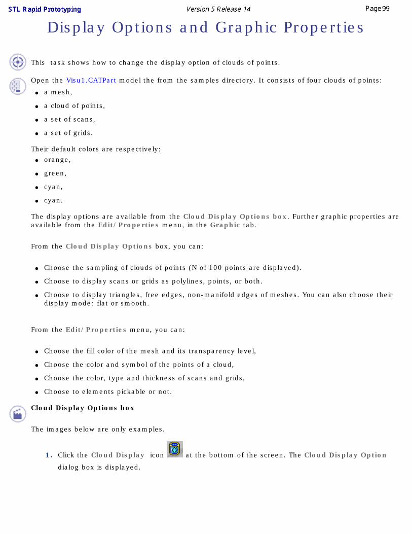
Display Options and Graphic Properties
This task shows how to change the display option of clouds of points.
Open the Visu1.CATPart model the from the samples directory. It consists of four clouds of points:
● a mesh,
● a cloud of points,
● a set of scans,
● a set of grids.
Their default colors are respectively: ● orange,
● green,
● cyan,
● cyan.
The display options are available from the Cloud Display Options box. Further graphic properties are available from the Edit/Properties menu, in the Graphic tab.
From the Cloud Display Options box, you can:
● Choose the sampling of clouds of points (N of 100 points are displayed).
● Choose to display scans or grids as polylines, points, or both.
● Choose to display triangles, free edges, non-manifold edges of meshes. You can also choose their display mode: flat or smooth.
From the Edit/Properties menu, you can:
● Choose the fill color of the mesh and its transparency level,
● Choose the color and symbol of the points of a cloud,
● Choose the color, type and thickness of scans and grids,
● Choose to elements pickable or not.
Cloud Display Options box
The images below are only examples.
1. Click the Cloud Display icon at the bottom of the screen. The Cloud Display Option
dialog box is displayed.

2. Select the cloud to modify. Display options are proposed according to the type of the cloud
selected:
Following options are not yet available:
● Protected,
● Orientation,
● Shrink,
● Normal.
3. For the cloud of points, you can choose to display only a percentage of the points making the
cloud, using the Sampling option. By default, 100% of the points are displayed. You can change
this value with the associated spinner.

Sampling=100 Sampling=25
The Symbol options are not available in that box, but in the Graphic Properties menu.
For the sets of scans or grids, you can display them as line of points or points or both:
For the mesh, you can: ● display the triangles,

● visualize only the vertices for a lighter display (do not forget to de-activate the Smooth, Flat or
Triangles options)
instead of

● the free edges in yellow,
● the non-manifold facets and their vertices in bold white lines.
● If you choose the display of triangles, the triangles accepting a non-manifold edge have their edges displayed as regular white lines.

● display the mesh as a smooth or a flat mesh.
or
The free edges displayed are those of the complete cloud of points: ● if you activate only a portion of a cloud of points, the free edges of that portion are not displayed.

● if you remove a portion of a cloud of points, the free edges of the remaining portion are displayed.
● If you move a cloud of points or a mesh, its graphic display options (not the graphic properties) are lost.
● The display options are not saved in the CATPart while the graphic properties are.
Edit/Properties menu (Graphic tab)
For more information about this menu, please refer to the Displaying and Editing Graphic Properties chapter in the CATIA Infrastructure user's guide.
The images below are only examples.

You can access this menu through Edit/Properties, or through the pop-up menu of the element, or display the Graphic Properties toolbar (View/Toolbars/Graphic Properties).
or

● The color displayed in the Graphic Properties toolbar applies to meshes only.
● The graphic properties are saved in the CATPart.
● Use Fill/Color and Transparency to modify the color and transparency of meshs:
Please note that : ● the color of mesh free edges is yellow, and is not editable,
● the color of non-manifold edges is white, and is not editable,
● the default color of scans has changed to cyan.
For a higher transparency quality, go to Tools/Options/Display/Performances and check the High (Alpha blending) option.

● Use Edges/Color, Line type and Thickness to modify the display of scans and grids or of the triangles of a mesh :
● Use Points/Color and Symbol to modify the display of clouds of points:
● Use the Pickable check box to make an element pickable or not, and choose the pick option in the list below.
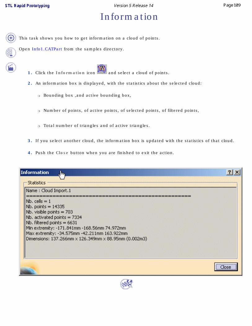
Information
This task shows you how to get information on a cloud of points.
Open Info1.CATPart from the samples directory.
1. Click the Information icon and select a cloud of points.
2. An information box is displayed, with the statistics about the selected cloud:
❍ Bounding box ,and active bounding box,
❍ Number of points, of active points, of selected points, of filtered points,
❍ Total number of triangles and of active triangles.
3. If you select another cloud, the information box is updated with the statistics of that cloud.
4. Push the Close button when you are finished to exit the action.

InteroperabilitySTL Rapid Prototyping complies with the following CATIA V5 standards:
Updating Your DesignUsing the Historical Graph
Creating DatumsPoints in Generative Shape Design

Updating Your Design
This task explains how and when you should update your design.
The point of updating your design is to make the application take your last operation into account. Indeed some changes to geometry or a constraint may require rebuilding the part. To warn you that an update is needed, CATIA displays the update symbol next to the part name and displays the corresponding geometry in bright red.To update a part, the application provides two update modes:
● automatic update, available in Tools -> Options -> Mechanical Design -> Assembly Design ->
General tab. If checked, this option lets the application update the part when needed.
● manual update, available in Tools -> Options -> Mechanical Design -> Assembly Design ->
General tab, it lets you control the updates of your part. You simply need to click the Update icon
whenever you wish to integrate modifications.
Non-updated wireframe and surface elements are displayed in red.
1. To update the part, click the Update icon .
A progression bar indicates the evolution of the operation.
You can cancel the undergoing update by clicking the Cancel button available in the Updating... dialog box.
● Keep in mind that some operations such as confirming the creation of features (clicking OK) do not require you to use the update command. By default, the application automatically updates the operation.
● The Update capability is also available via Edit -> Update and the Update contextual command.
● To update the feature of your choice, just select that feature and use the Local Update contextual
command.

● Besides the update modes, you can also choose to visualize the update on the geometry as it is happening by checking the Activate Local Visualization option from the Tools -> Options -> Infrastructure -> Part Infrastructure, General tab.
In this case, as soon as you have clicked the Update icon :
1. the geometry disappears from the screen2. each element is displayed as it is updated, including elements in No Show mode. Once
they have been updated, they remain in No Show mode.
Interrupting Updates
This task explains how to update a part and interrupt the update operation on a given feature by means of a useful message you previously defined.
Open any document containing geometric elements.
1. Right-click an element from the specification tree and choose the Properties contextual menu item.
The Properties dialog box is displayed.
2. From the Mechanical tab, check the Associate stop update option.
3. Enter the text to be displayed when the updating process will stop when reaching this element.
4. Click OK to confirm and close the dialog box.
The Stop Update.1 feature is displayed in the specification tree, below the element for which it was defined.

5. Whenever it is needed, click the Update icon to update the whole part.
The updating process stops after having updated the element selected above, and issues the
message as has been defined earlier:
6. Click Yes or No, depending on what you intend to do with the geometry created based on the
selected element.
Would you no longer need this capability, you can: ● right-click the element for which the stop was defined, choose the Properties contextual command and
check the Deactivate stop update option from the Mechanical tab: the update will no longer at this element.
You notice that when the capability is deactivated, the Stop Update icon changes to: in the
specification tree.
● right-click Stop Update.1 from the specification tree, and choose the Delete contextual command.

Using the Historical Graph
This command is only available with the Generative Shape Design 2 product.
This task shows how to use the Historical Graph.
1. Select the element for
which you want to
display the historical
graph.
2. Click the Show
Historical Graph icon
.
The Historical Graph dialog box appears.
The following icon commands are available. ● Add graph
● Remove graph
● Reframe graph
● Surface or Part graph representation
● Parameters filter
● Constraints filter.
3. Just close the dialog box to exit this mode.

Creating Datums
This task shows how to create geometry with the History mode deactivated. In this case, when you create an element, there are no links to the other entities that were used to create that element.
1. Click the Create Datum icon to deactivate the History mode.
It will remain deactivated until you click on the icon again.
If you double-click this icon, the Datum mode is permanent. You only have to click again the icon to deactivate the mode.
A click on the icon activates the Datum mode for the current or the next command.
The History mode (active or inactive) will remain fixed from one session to another: it is in fact a setting.
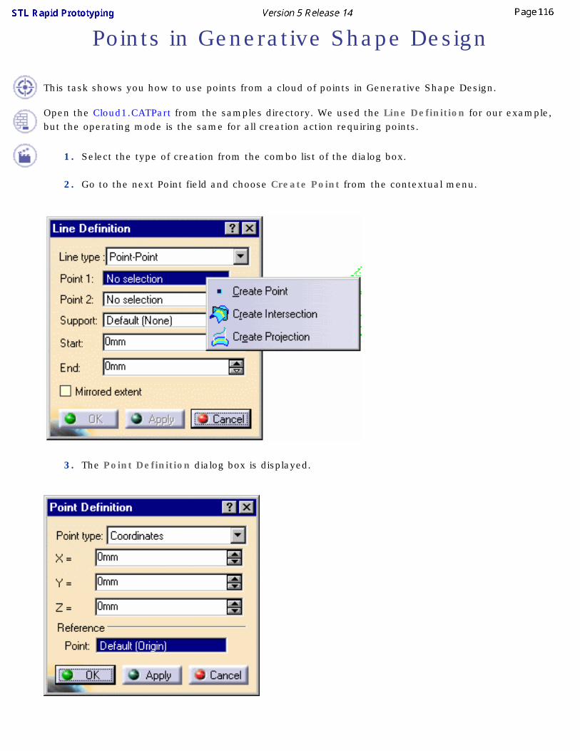
Points in Generative Shape Design
This task shows you how to use points from a cloud of points in Generative Shape Design.
Open the Cloud1.CATPart from the samples directory. We used the Line Definition for our example, but the operating mode is the same for all creation action requiring points.
1. Select the type of creation from the combo list of the dialog box.
2. Go to the next Point field and choose Create Point from the contextual menu.
3. The Point Definition dialog box is displayed.

4. Click a point on the cloud. Its coordinates are displayed in the Point Definition dialog box. Click
OK to confirm the creation of this point.
5. In the main dialog box, go to the next Point field and repeat the above steps as many times as
necessary.
6. If necessary, push the Point icon on the right of the Point field to modify the point you have
created: the Point Definition dialog box is displayed and updated according to your pick on the
cloud.

Managing Geometrical Sets Geometrical sets enable to gather various features in a same set or sub-set and organize the specification tree when it becomes too complex or too long. You can put any element you wish in the geometrical set, it does not have to be structured in a logical way. The order of these elements is not meaningful as their access as well as their visualization is managed independently and without any rule.
This task shows how to manage geometrical sets within the specification tree. This involves:
● inserting a geometrical set
● removing a geometrical set
● changing body
● sorting the contents of a geometrical set
● reordering components
You will find other useful information in the Managing Groups and Hiding/Showing chapters.
● You can insert and manipulate geometrical sets in the specification tree in much the same way as you manage files in folders.
● These management functions have no impact on the part geometry.
● You should refer to the Copying and Pasting section for information about how geometrical sets can be used in a part edition context.
● When loading the Generative Shape Design workbench, a Geometrical Set automatically becomes the current body. This also means that only the results of the Hybrid Body, i.e. the result of all the operations performed on geometry, is visible and not any intermediate state of the Hybrid Body.
● You can define the Generative Shape Design feature that is to be seen when working with another application, such as Generative Structural Analysis for example.
To do this, while in the Generative Shape Design workbench:
1. Choose the Tools -> External View... menu itemThe External View dialog box is displayed.
2. Select the element belonging to a Geometrical Set that should always been seen as the current element when working with an external application.
3. Click OK in the dialog box.

The selected element will be the visible element in other applications, even if other elements are created later in the .CATPart document, chronologically speaking.
To check whether an external view element has already been specified, choose the Tools -> External View... menu item again. The dialog box will display the name of the currently selected element. This also allows you to change elements through the selection of another element. Note that you cannot deselect an external view element and that only one element can be selected at the same time.
Open any .CATPart document containing Geometrical Sets.You can also open the GeometricalSets2.CATPart document.
Inserting a Geometrical Set
1. In the specification tree, select an element as the location of the new geometrical set.
This element will be considered as a child of the new geometrical set and can be a geometrical set
or a feature.
2. Select the Insert -> Geometrical Set menu
command.
The Insert Geometrical Set dialog box is
displayed.
The Features list displays the elements to be
contained in the new geometrical set.
3. Enter the name of the new geometrical set.
4. Use the Father drop-down list to choose the body where the new geometrical set is to be inserted. All destinations present in the document are listed allowing you to select one to be the father without scanning the specification tree. They can be:
❍ geometrical sets
❍ parts
5. Select additional entities that are to be included in
the new geometrical set.
If all selected entities belong to the same geometrical set, the father of the new geometrical set is automatically set to the father of these entities.
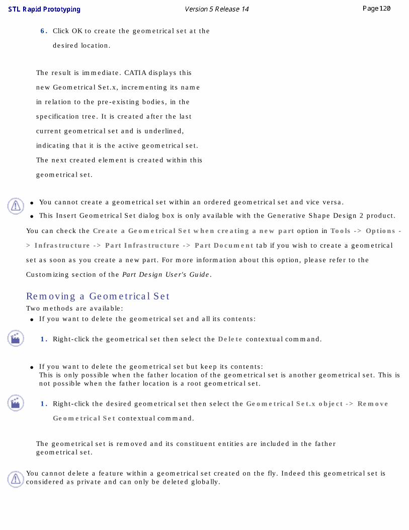
6. Click OK to create the geometrical set at the
desired location.
The result is immediate. CATIA displays this
new Geometrical Set.x, incrementing its name
in relation to the pre-existing bodies, in the
specification tree. It is created after the last
current geometrical set and is underlined,
indicating that it is the active geometrical set.
The next created element is created within this
geometrical set.
● You cannot create a geometrical set within an ordered geometrical set and vice versa.
● This Insert Geometrical Set dialog box is only available with the Generative Shape Design 2 product.
You can check the Create a Geometrical Set when creating a new part option in Tools -> Options -
> Infrastructure -> Part Infrastructure -> Part Document tab if you wish to create a geometrical
set as soon as you create a new part. For more information about this option, please refer to the
Customizing section of the Part Design User's Guide.
Removing a Geometrical SetTwo methods are available:
● If you want to delete the geometrical set and all its contents:
1. Right-click the geometrical set then select the Delete contextual command.
● If you want to delete the geometrical set but keep its contents:
This is only possible when the father location of the geometrical set is another geometrical set. This is not possible when the father location is a root geometrical set.
1. Right-click the desired geometrical set then select the Geometrical Set.x object -> Remove
Geometrical Set contextual command.
The geometrical set is removed and its constituent entities are included in the father geometrical set.
You cannot delete a feature within a geometrical set created on the fly. Indeed this geometrical set is considered as private and can only be deleted globally.
Moving a Geometrical Set to a New Body
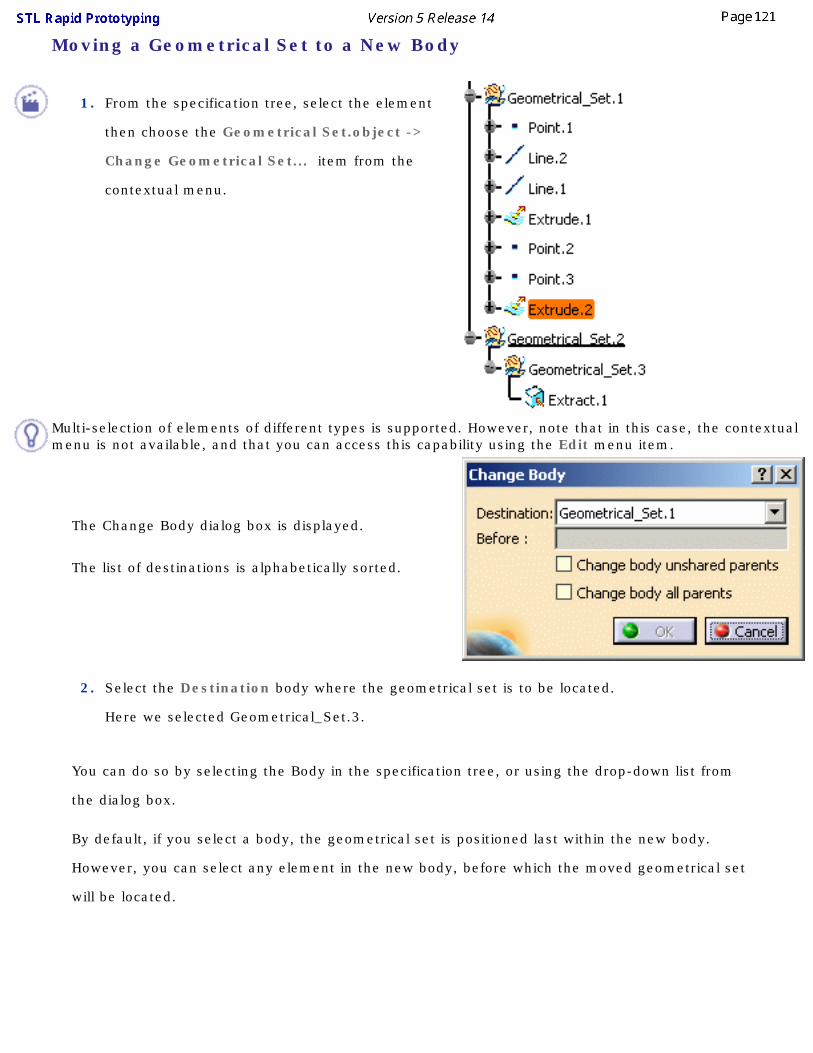
1. From the specification tree, select the element
then choose the Geometrical Set.object ->
Change Geometrical Set... item from the
contextual menu.
Multi-selection of elements of different types is supported. However, note that in this case, the contextual menu is not available, and that you can access this capability using the Edit menu item.
The Change Body dialog box is displayed.
The list of destinations is alphabetically sorted.
2. Select the Destination body where the geometrical set is to be located.
Here we selected Geometrical_Set.3.
You can do so by selecting the Body in the specification tree, or using the drop-down list from
the dialog box.
By default, if you select a body, the geometrical set is positioned last within the new body.
However, you can select any element in the new body, before which the moved geometrical set
will be located.

3. Select the element above which the one you
already selected is to be inserted.
You can directly select this positioning element. In this case the Destination field of the Change Body dialog box is automatically updated with the Body to which this second element belongs.
4. Click OK to move the geometrical set to the new
body.
The element selected first is moved to its new
location in the specification tree, but geometry
remains unchanged.
● Check the Change body unshared parents option to move all parents of the first selected element to its new location, provided these parents are not shared by any other element of the initial body.In this case, all the unshared parents are highlighted prior to the move.

● Check the Change body all parents option to move all parents of the first selected element to its new location, regardless of whether these parents are used (shared) by any other element of the initial body.In this case, all the parent elements are highlighted prior to the move.
● You can move a whole branch, i.e. a whole body and its contents, at a time.Here we moved Geometrical_Set.3 last in Geometrical_Set.1.
Sorting the Contents of a Geometrical SetYou may need to sort the contents of a Geometrical Set, when the geometric elements no longer appear in the logical creation order. In that case, use the Auto-sort capability to reorder the Geometrical Set contents in the specification tree (geometry itself is not affected).

The Geometrical_Set.1 contains two extruded surfaces based on point-point lines. The specification tree looks like this:
1. Right-click the Geometrical_Set.1 from the
specification and choose the Geometrical_Set.1
object -> AutoSort command.
Instantly, the contents of the Geometrical Set
are reorganized to show the logical creation
process.
The geometry remains unchanged.
Reordering Components within a Geometrical Set This capability enables you to reorder elements inside the same geometrical set.
1. Right-click the Geometrical_Set.1 from the
specification tree and choose the Ordered
Geometrical Set.1 object -> Reorder Children
command.
The Reorder Children dialog box is displayed.
2. Select an element.
3. Use the arrows to move an element up or down.
Reordering Features

The Reorder command allows you to move a feature in a Geometrical Set. These features can be:● solids
● shape features
● sketches
Replacing Features This capability is only available on shape features.
Please refer to the Replacing or Moving Elements chapter in the Part Design User's Guide. To manage this capability, the Do replace only for elements situated after the In Work Object
option is available in Tools -> Options -> Part Infrastructure -> General tab. It allows you to make the Replace option possible only for features located below the feature in Work Object and in the same branch.

Workbench DescriptionThis chapter describes the menus, sub-menus, items and toolbars of the workbench.
Menu BarCreation ToolbarsAnalysis ToolbarsSpecification Tree

Menu BarThis chapter describes the menus available in the workbench. Other menus are documented in the Infrastructure User's Guide.
Start SmarTeam File Edit View Insert Tools Windows Help
Start
Starts the STL Rapid Prototyping Workbench
Insert For See
STL Import Importing Files
STL Export Exporting Meshes to STL
Edition:
Activating a Portion of a Cloud of Points Removing Elements
Mesh:
Mesh Regeneration

Tessellating an Object
Offsetting a Mesh
Flip Edges
Smoothing Meshes
Mesh Cleaner
Filling Holes on Meshes
Decimating Meshes
Operation:
Merging Meshes
Splitting Meshes
Trim/Split
Information Analysis
For the other menu items, please refer to the Infrastructure User's Guide.

Creation ToolbarsThey are the following:
STL FilesEditionMesh
OperationsAnalysis

STL FilesFor See
ImportImporting Files
Export Exporting Meshes to STL

STL EditionFor See
ActivationActivating a Portion of a Cloud of Points
Remove Removing Elements
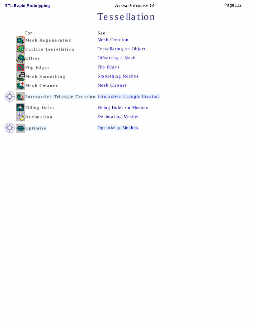
TessellationFor See
Mesh Regeneration Mesh Creation
Surface Tessellation Tessellating an Object
Offset Offsetting a Mesh
Flip Edges Flip Edges
Mesh Smoothing Smoothing Meshes
Mesh Cleaner Mesh Cleaner
Interactive Triangle Creation Interactive Triangle Creation
Filling Holes Filling Holes on Meshes
Decimation Decimating Meshes
Optimize Optimizing Meshes

OperationsFor See
Meshes MergeMerging Meshes
Split Splitting Meshes
Trim/Split Trim/Split

AnalysisFor See
Information Information

STL Display Options ToolbarIt contains the following tool:
Display Options and Graphic Properties

Specification Tree
The specification tree portion specific to STL Rapid Prototyping looks like this:
Geometrical Sets
Groups
Output of Import
Output of Mesh Regeneration
Output of Surface Tessellation
Output of Offset
Output of Polygon Smoothing
Output of Meshes Merges
Output of Split
Output of Mesh Cleaner
Output of Trim/Split

Glossary
Aactivate This function is used to define a particular portion of a cloud for further operations.
Ccell A polygon may consist of several cells (i.e. sub-clouds): for example, the polygon below
consists of two cells.
characteristic line They are particular lines corresponding for instance to curvature variations (fillets start/end) or sharp edges, ...
Fflipping edge An edge common to two triangles of a polygon may be flipped, that is rotated, to respect
the shape a sharp edge of the tessellated part.
M

mesh A mesh consists of a set of polygonal faces (triangles) which represent the surface of a 3D model. A triangulation is computed to describe the neighborhood relation of all points.
A mesh can be used to check the quality of the points, or can be processed in other applications.
A mesh may present some irregularities such as:
● Corrupted triangles, i.e. triangles that have the same vertex twice,
● Duplicated triangles, i.e. triangles that share the same three vertices,
● Non-manifold edges, i.e. edges shared by more than two triangles,
● Non-manifold vertices, i.e. vertices shared by two or more connected shells.
A mesh may also present some structural problems such as:
● Orientation problems, i.e. all the triangles are not oriented in the same direction,
● Isolated triangles, i.e. triangles belonging to small connected areas of the mesh,
● Disconnected zones, i.e. the mesh is made of several disconnected zones,

● Triangles with long edges.
Rremove This function deletes physically points from the cloud of points. The points can not be
recovered.
Sshading A tessellation can be visualized in shaded mode. This mode is a method for visualizing the
point data and getting an impression of its quality.
Index
AActivate
command
Activation Analyze
Mesh Cleaner AutoSort Open Body
command
BBounding box
Import
CChange Body
command Chordal Deviation
Decimation Cloud Display
Cloud Display Options
command
Graphic properties
Polyline and Point
Sampling
Triangles Cloud Display Options
Cloud Display command
Activate
AutoSort Open Body
Change Body
Cloud Display
Decimation
Export
Fill Holes
Flip Edges
Import
Information
Insert Geometrical Set
Merge
Mesh Cleaner
Mesh Creation
Mesh Regeneration
Offset
Properties
Remove
Remove Geometrical Set
Reorder Body
Show Historical Graph
Split a Mesh or a Cloud
Tessellate an Object
Update Constrained
Meshing creating
datum Creating a shell
Offsetting the mesh Current Triangle Count
Decimation
Ddatum
creating Decimation
Chordal Deviation
command
Current Triangle Count
Edge Length
Free Edge Deviation
Target Percentage
Target Triangle Count Deletion
Mesh Cleaner Delimitors
Import Depth
Flip Edges Direction
Import Distinct
Mesh Cleaner
EEdge Length
Decimation
elements Export
command
Stl

FFacets
Import Fill Holes
command
Hole size
Points insertion
Sag
Selection of holes
Shape
Step Flip Edges
command
Depth Formats
Import Free Edge Deviation
Decimation Free edges
Import
Ggeometrical sets
inserting
managing
removing
reordering Graphic properties
Cloud Display Grouped
Import
Mesh Cleaner

Hhistory Hole size
Fill Holes
IImport
Bounding box
command
Delimitors
Direction
Facets
Formats
Free edges
Grouped
Minimal point quality
Statistics
System
Update Information
command Insert Geometrical Set
command inserting
geometrical sets
Interoperability Isolated Triangles
Mesh Cleaner

LLong Edges
Mesh Cleaner
Mmanaging
geometrical sets Max Deviation
Mesh Smoothing Merge
command Mesh Cleaner
Analyze
command
Deletion
Distinct
Grouped
Isolated Triangles
Long Edges
Orientation
Preview colors
Split in Connected Zones
Statistics
Structure Mesh Creation
command Mesh Regeneration
command Mesh Smoothing
Max Deviation Meshing
Constrained
Mode

Neighborhood
Sphere Minimal point quality
Import Mode
Meshing moving
open bodies
NNeighborhood
Meshing
non-updated
OOffset
command
Offsetting the mesh
Creating a shell open bodies
moving
sorting Orientation
Mesh Cleaner
PPick
Remove Points insertion
Fill Holes Polygonal

Trap Polyline and Point
Cloud Display Preview colors
Mesh Cleaner Properties
command
RRectangular
Trap Remove
command
Pick
Trap Remove Geometrical Set
command removing
geometrical sets Reorder Body
command reordering
geometrical sets
SSag
Fill Holes
Tessellate an Object Sampling
Cloud Display Selection of holes
Fill Holes Shape

Fill Holes Show Historical Graph
command sorting
open bodies Sphere
Meshing Spline
Trap Split a Mesh or a Cloud
command Split in Connected Zones
Mesh Cleaner Statistics
Import
Mesh Cleaner Step
Fill Holes
Tessellate an Object Stl
Export Structure
Mesh Cleaner System
Import
TTarget Percentage
Decimation Target Triangle Count
Decimation Tessellate an Object
command
Sag
Step

Trap
Polygonal
Rectangular
Remove
Spline Triangles
Cloud Display
UUpdate
command
Import
updating