sticks and tissue no 99 – february 2015sticksandtissue.yolasite.com/resources/2015/st99.pdf ·...
TRANSCRIPT

1
Sticks and Tissue No 99 – February 2015 If you can contribute any articles, wish to make your point of view known etc please send to or phone 01202 625825 [email protected] The content does not follow any logical order or set out, it’s “as I put it in and receive”. Thanks to Mark Venter back issues are available for download from http://www.cmac.net.nz Writings and opinions expressed are the opinion of the writer but not necessarily the compiler/publisher of Sticks and Tissue.
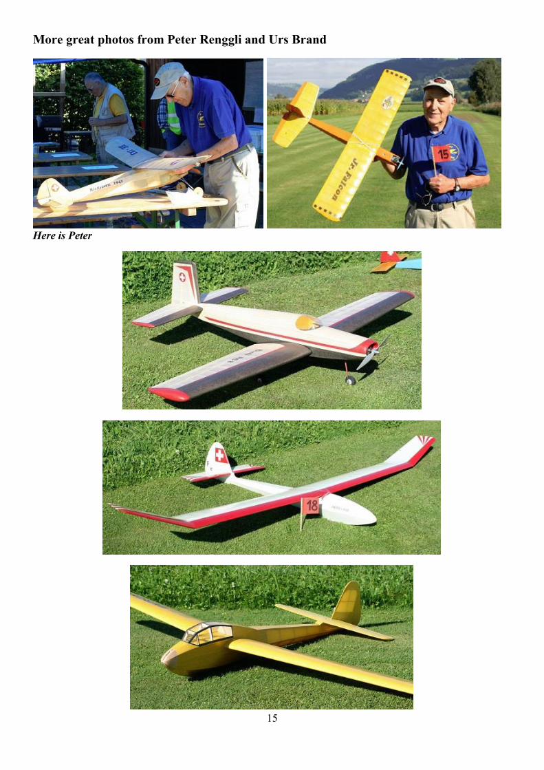
Peter Renggli, Urs Brand photo

2
From Charlie Stone (Western Australia) Thanks for the latest S & T. I always enjoy it and the FF photography is wonderful. I was inspired by the 1958 article on scale team racing, though I don't remember seeing it at the time. Just to show that scalish models can succesfully compete (at least in the vintage categores) I have attached some photos of my close to scale Hawker Tempest that conformed to the rules of vintage A class team race. Some years ago this model (skillfully flown by my T/R pilot Norm Kirton) won the Western Australian State championships for Vintage A competing with more conventional racer types. It was painted in the colours of one of the Tempests flown by Pierre Clostermann (who wrote the excellent book `The Big Show`) and powered by an Oliver Tiger (what else). It had a flying speed of just over 90 MPH. I must apologise for the quality of the photos as they were just snaps taken at the time. I have also included a couple of shots of my most recent control line model, a Veco Chief. This one is powered with a Veco .35 and weighs 33 1/2 ounces ready to fly , but with an empty tank. The name Kawliga comes from the line in Hank Williams song of the same name. `Kawliga was a wooden indian`. And this one definitely is.

3

4

5
Hoh Fang-Chiun’s Acrobator a sports / stunt controlliner for 1 ½ cc engines fromModel Aircraft May 1958
It is not claimed that Acrobator will perform as well as the larger stunt models that have been discussed in connection with the new schedule recently, but it has certain advantages they do not possess. It is small, cheap both to build and fly and can be flown in small spaces, so these qualities allied to its good looks make it just the job for the “sporting” brigade. Start construction with the mainplane. Select a hard, straight and warp-free 3/8in. sq. strip for the mainspar, and cut the ribs front 1/16 in and 3/32 in. medium sheet balsa as
indicated on the plan, noting that the two root ribs are 1/16 in undersize on both edges. Before assembling the ribs on the main spar. Securely cement the hardwood bellcrank mount at the centre of the spar. Don’t forget to cut away approximately 1/8in. on the top of the spar at the bellcrank mount in order to ensure a free movement. As the wing has a symmetrical airfoil, it has to be built “off’ the plan.” Slide and cement the ribs onto the mainspar and check that they line up correctly, then cement the 3/16 in. sheet trailing edge and 1/4 in. sq. leading edge in place, finally, add the 3/16 in. sheet tips. In order to facilitate the tip covering, and at the same time make it smoother, soft scrap balsa is cemented at the leading and trailing edges. Do not forget the 1/2-oz. weight in the starboard wing tip. Before sheet covering the centre part of the wing, bolt the bellcrank assembly and solder all the necessary wires, etc., in place. The wing can now he covered either with silk or tissue, but be sure that the grain of the covering material runs spanwise to minimize “sag.” Start the fuselage by cutting out all the formers and the two sides, using hard sheet for the latter. Solder up the fuel tank from thin brass making sure that the engine feed tube is long enough to suit your engine. Bend the U/C from good quality steel wire and bind it securely to the 1/8in. ply former FB with heavy thread and plenty of cement. Cut the engine bearers from hardwood stock and the parts arr now ready for assembly. First cement FA and BB to the bearers. Next, cement the tank just behind FA and insert scrap balsa under the tank to prevent it vibrating loose, then complete tise nose assembly by cementing former FC in place. The nose assembly can now be joined to the fuselage sides and after it is completely dry, FD nd FE are added in place Next join the sides at the rear, but do NOT cement FF and FG in yet. Place FF and FG just behind FE with the push-rod holes in alignment, and hold these together with pins. Join the wing to the fuselage by inserting the push-rod through the holes in the forment and the slot on the starboard fuselage side, and then cernent the wing firmly in place. Now FF and FG can be cemented in. Cover the fuselage bottom and top rear with 1/16 in. sheet, and the top front with soft 3/16 in. balsa when dry sanding the latter to the appropriate section. Complete the engine mount and nose in the usual manner. A soft balsa block forms the rear fuselage top, but be sure when cementing it in place to leave an 1/8in. gap for thetailplane. The tailplane and fin which are from 1/8in. medium Slices can now be cemented in place, but check that there is enough movement (about 40˚ up and clown is sufficient). Complete the model by fitting the canopy; a commercial one (somewhat modified) can be used, but if that is uniavailable, a home-made one can be moulded from 0.016 in. sheet celluloid. A good idea is to instal a class A team race pilot for added realism- If you think it is troublesome to mould your own canopy, you can fit instead a hollowed soft balsa block and Paint this silver when fmished.

6
Every modeller has his own favourite finishing methods, but here is how the original model was finished: first I brushed on to the bare balsa surfaces one coat of thin clear dope, followed by two Coats of wood filler, these being sanded with fine paper between each coat. All the wood surfaces were then covered with lightweight tissue and received two coats of thick clear dope before wet sanding with No. 300 Wet-and-dry paper. A further thin Coat of dear dope was then applied before colouring. The wing was covered with American Rayspan (similar to heavy Modelspan) and had four coats of thick clear dope with the addition of a small quantity of castor oil in order to make the covering flexible. In order to save weight no colour dope was used. The complete model without fuel should turn out to be around 12-0zs. Before attempting any flight, check that the model balances correctly; the prototype did not need any adjustment to bring the C.G. to the correct position. Use 0.010 in. dia, steel or light laystrate wire for best results, coupled with a 7 X 6 in. or 7 X 5 in. wooden airscrew for a 1.5 c.c. diesel. The length of the lines will depend on weather conditions and may vary from 30 ft. in windy weather to 45 ft. in a calm. The model is very manoeuvrable and goes through most patterns with ease. The inside loop can be performed with almost any engine speed. However, never try any complicated figure unless the engine is running at peak revs. From Karl Gies This picture was taken in 1968 and is close to Rancho Milpitas Junior High located in Milpitas, CA where I taught science classes. I am holding a John O’Donnell design, The Delinquent, sort of a beginners small unlimited class model and a terrific flyer. I was thirty-one at the time. The Delinquent flew for me until about seven years ago when the model was torched lighting the d.t. I still grieve for this model and probably more had than two hundred flights with it.
This is an engine powered model and I used a hopped up Cox .049 & .051 so as to fly in both 1/2A & A classes. I can’t remember if this picture was taken in California or Butte. I still have the model which needs some repairs. It was built in 1967. Pretty sure this pic was in Calif.

7
My 5th grade contest winners in Butte, America circa 1971, holding their JASCO FLASH X-18 rubber power models designed and kitted by Frank Zaic These kids took the first four places in the Hillcrest School Fifth Grade Model Airplane Contest. The girl, Allison McKenzie won first and I can’t remember the other kids names. I think the kid on the far left was Jimmy ? and the kid on the far left was a kid named Ed (?) The kid next to Allison on the right, tall kid, took second. We had some flights of over a minute with these models. Butte, Montana was just a great place to live & teach. This was back in the skinny necktie days cheers, Prior to this I taught science at Rancho Milpitas Jr. High in Milpitas, CA and had a model airplane club at this school. I will post a picture of some of those kids and their models also. karl gies p.s. to Jeff & Fred, please identify everyone for me.

8
Much credit has to be given to Frank Zaic who designed & kitted this fine beginners rubber powerd model, the Flash X-18 as all of the models flew quite well and it was a long contest on a fine spring day in Butte, America. Franks also included at no cost extra parts for reparis and also a few extra kits in case a kid did not have money to purchase a kit. To Jeff & Fred, please help me identify everyone. Jeff, is that you on the far left in the third row standing? cheers, karl gies p.s. Jeff & Fred please help me with all of the kids’ names

9
The following three photos Some members of my Rancho Milpitas Junior High model airplane club in Milpitas, California I can identify two boys in the picture. Second from left is Mitch Koch holding his “Little Mavis", a design from AeroModeller Magazine and a fine flyer. Standing to his right is Lothar Maier holding the winder, a converted Sears hand drill. Lothar won the Academy of Model Aeronautics, Hobby Industries of America & Navy sponsored model airplane contest for Northern California which included a paid trip to the national AMA-HIAA-Navy contest back east complete with a Navy carrier cruise. Lothar did quite well back at that contest winning at least two events as I remember. In the second picture the boys are holding AMA Darts, Bill Warner’s Poly Wog design published in the Sig Air Modeller magazine, a Sig “Flip" Hand Launch Glider, and a Jetco towline glider called the “C” I think. Mitch Koch is on the far left and Lothar Maier is second from the right. I remember the other boys faces but not their names. The bottom picture shows Lothar Maier and another boy holding their “Oily Birds” which was a giant Delta Dart w/a Cox engine. The climbed well and glided like a rock. These boys were all good builders and flyers. In the background of the bottom picture is our flying field which was the only free flight field available in the Bay area. The year after this photo it became a housing sub division with I think the rather tacky name of “Jack & Jill”. I think this picture was taken in the spring of 1969. I lost contact with all of these kids except Lothar who wrote me a letter or two way back when. Lothar is now the CEO of Linear Technology Corporation. cheers, karl (the remarkable thing about teaching is that you learn so much yourself)

10

11
A 38” span sports biplane for up to1.5 c.c. motors and featuring a timer operated rudderby W. Lister from Model Aircraft December 1958
This model was designed as an easy to build, rugged sportster, to satisfy a desire to have a model that was semi-scale but eye catchingly different. Thc original has now completed many flights, and never fails to excite attention, both for its looks and also the “Out of the rut” performance that the timer-operated rudder gives it. Trace the formers from the plan onto the appropriate balsa or ply, cut out, then chamfer the edges carefully to allow for the curvature of the sheet sides. Select some pliable quarter grain 1/16 in. sheet for the sides, cut to shape, and sand lightly before commencing construction. It is essential that the formers are situated exactly as shown, so mark their positions on the inside face
of the sides. All formers aft of the timer are bushed with metal tubing to accommodate the cain operating wire, so insert these, then bend to shape and bind and cement to its former the undercarriage. Glue the engine bearers and the wing pylon to the appropriate formers, lining up accurately with a set square, and when dry this will form an accurate jig for the rest of the fuselage construction. The sides are now cemented to the bearers, the cam operating wire bent to shape, formers 6, 7 and 8 threaded over same and then cemented in place. Now add the timer box and fuel tank and do all the necessary soldering on the cam push rod. This completes the tricky part of the construction, everything else being quite straight forward, the top of the fuselage being planked in the usual way with strips of 1/16in. sheet before the bottom sheeting is added.
The wings and tail are entirely orthodox and will present no problems, so all you have to do is press on in the usual way, and finish the model off with a gay colour scheme, perhaps on the lines of the pre-war American military biplanes. One word of warning, though, don’t be too lavish with the colour dope—it’s heavy—and too much weight will hamper Gadfly’s performance.

12
Allen-Mercury A-M 156 1.5 cc diesel One of the most impressive model diesels, as regards power output, that has yet áppeared on the world market is the 1 c.c. Allen- Mercury “ 10.” When one of these engines was tested for this series (July 1956 issue) it delivered an output of no less than 0.118 b.h.p. This is the highest performance yet realised with a 1 c.c. engine. Equal to a specific output of 0.118 b.h.p. / litre, it is also the highest ever recorded for a plain hearing diesel and is one of the highest performances yet reached by a modeldiesel irrespective of type. In its external dimensions and weight, the A-M “10” resembles many motors of the 1.5 c.c. class and some of its performance almost certainly stems from the added rigidity and better internal cooling of the extra material thicknesses involved.
It is no accident that the “ 10 “ is to all outward appearances a 1.5 class motor for it was, in fact, based on a prototype which now appears, in its production version, as the new A-M “15.” Both 1 c.c. and 1.5 c.c. engines were developed concurrently and when production was begun more than two years ago, it was merely a matter of deciding which capacity should be offered first. The “ 10 “ got the vote and it was, presumably, due to its tremendous success and the resulting demand, that we have had to wait so long for the “15.” Apart from the colour of the cylinder barrel and tank (green in the case of the “ 10” and blue for the 15 “, there is only the slightly greater diameter between the fins of the “ 15” cylinder barrel, to outwardly identify the two. Internally, it is the cylinder, piston and con-rod that distinguish the “ 15” from the “ 10.” The lower assemblies, comprising crankcase and crankshaft, are identical and, in fact, interchangeable. The stroke is the same for both engines and the extra capacity of the “15” is gained by an increase of 0.094 in. (according to two units measured) on the bore. It is true to say that the “ 15” is, in effect, a bored out “ 10.” Cylinder liners are basically similar and even have the same port areas and give the same timing. However, the upper part of the liner of the “15” is turned to a larger outside diameter so that a wall thickness still exceeding 0.050 is maintained. Other modifications include a heavier gudgeon pin (9/64. in. instead of 1/8in.) and, of course, a new con-rod to accommodate this. It must be admitted that, having regard to the limited extent to which the “15”“ differs from the “10” one would have been prepared to accept a relatively modest improvement in performance, perhaps no more than 25 per cent, which would have still been sufficient to place the “15” well up among the leaders of the 1.5 c.c. class. In actual fact, our test “15” responded to the extent of some 38 per cent., raising the b.h.p. to a figure which is one of the highest yet achieved by any 1.5 c.c. motor and which more than equals the outputs of the best Continental ball-bearing 1.5 diesels, that have been claiming some attention recently. On the construction side, the A-M “15” exhibits the same high standard of internal fits and finishes as the “ 10.” Both these engines are, of course, quite modestly priced and it is satisfying to see that most of the money has been spent where it matters most and will contribute to performance and durability. Specification Type: Single-cylinder, air-cooled, reverse-flow scavenged two-stroke cycle, compression ignition. Shaft type rotary-valve induction. No sub-piston supplementary air induction. Bore: 0.521 in. Stroke: 0.430 in. Swept Volume: 0.0917 Cu. in. = 1.502 cc. Stroke/Bore Ratio: 0.825 : 1. Weight: 3.1 oz. including tank. General Structural Data - Pressure diecast crankcase and main bearing housing in LAC. 112A alloy. Crankshaft of S.14 steel, hardened, with disc-web and running direct in crankcase material. Splined shaft end for prop driver. Meehanite cylinder liner, flanged at exhaust port level and clamped to crankcase via cylinder barrel and three long screws. Cylinder barrel of duralumin. Meehanite piston with full-floating gudgeon pin. Connecting-rod machined from forged dural bar. Spraybar type needle-valve assembly. Beam

13
mounting lugs. Test Engine Data Running time prior to test: 2 hours. Fuel used: Mercury No. 8. Performance Where the “ 15” scores mostly over the “ 10” is in its power/weight ratio for, with nearly 40 per cent more power, it is practically the same weight. In some countries (West Germany and Japan, for example) there are special F/F contest classes for engines not exceeding 1 c.c., and, of course, there is also the 1 c.c. class PAA-Load model. For such contests the “ 10” has proved ideal. The “ 15” will also have much to offer in classes where engine capacities are limited to 1.5 c.c. For open power work, it is worth noting that the “ 15” is up to 25 per cent. lighter in weight than the Continental ball-bearing 1.5’s of near-similar performance, added to which it is quickly interchangeable with the “10” for double class contest use with a single model, where appropriate. The handling characteristics of the “ 15” are very similar to those of the “10” and, therefore, are generally good. An initial start from cold was quickly achieved after choking the intake and starting remained easy on all prop sizes, only becoming a little more tricky when the diameter was reduced below 7 in. There was then the common tendency to “ bite “—i.e. for the prop to snap round and rap the finger—but since these small sizes correspond to loads allowing r.p.m., in the air, in excess of the b.h.p. peaking speed, this is, in any
case, relatively unimportant. The controls were excellent. Needle valve sensitivity was just about right, the only complaint with the test engine being that the needle tended to float about a little at high speeds, but this was quickly cured by squeezing up the thimble slightly. The compression adjustment was also responsive yet not critical and it was particularly pleasing to find that the contra piston remained firm in the bore, yet without any tendency to stick, irrespective of engine temperature—and the engine does run
very hot. As regards test performance, the curves speak for themselves. Maximum torque was achieved at around 10,000 r.p.m. and although b.m.e.p. was a little below that of the “ 10” it was still well above average for engines of this class. Below about 9,000 r.p.m. there was a considerable power loss as the engine warmed up (a drop in torque to the order of 10-15 per cent. was apparent between “cold” and “hot” readings) but beyond 10,000 r.p.m. the tendency disappeared and was entirely absent above12,000 r.p.m.—a normal tendency with diesels of this type. As regards ultimate power, a maximum output of 0.163 b.h.p. at slightly over 15,000 r.p.m. was achieved and this, needless to say, places the A-M “ 15” at the top of the tree as far as 1.5 c.c. engine performance is concerned. In all, the A-M “15” is a most worthy companion model to the 10,” and “ io” users will agree that it is scarcely possible to say fairer than that. Power/ Weight Rutio (as tested): 0.84 b.h.p./lb. Specific Output (as tested): 108 b.h.p./litre.
14
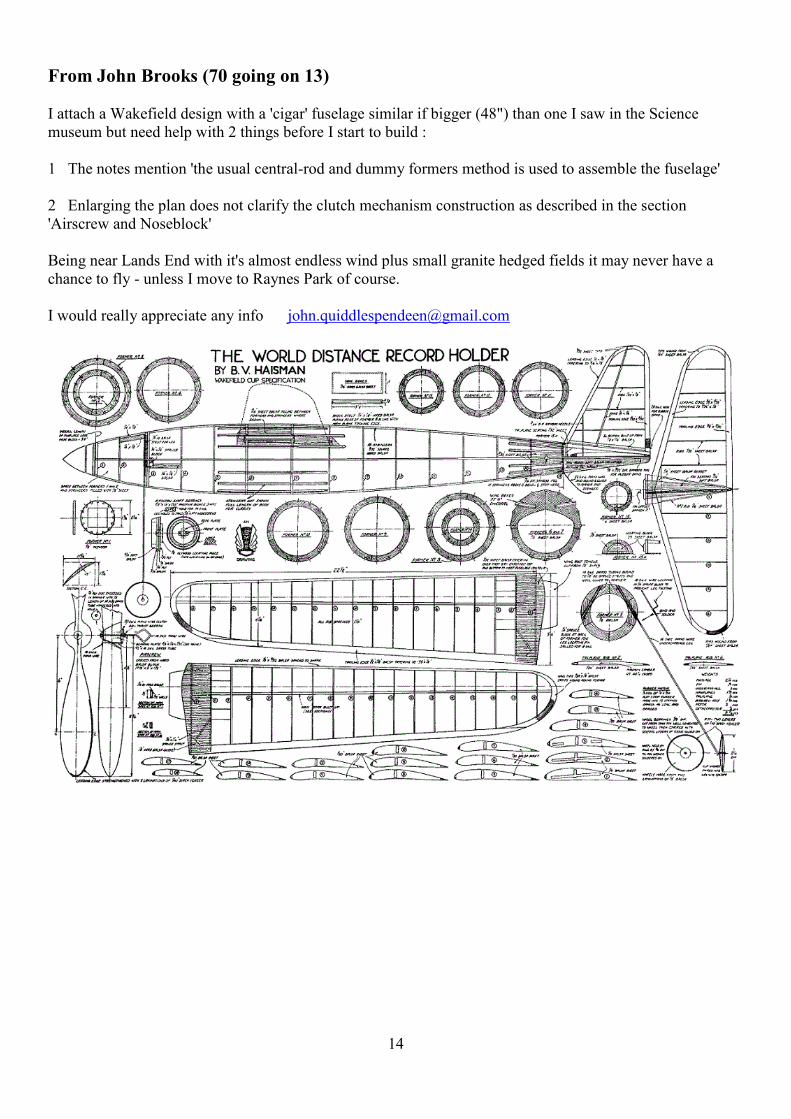
From John Brooks (70 going on 13) I attach a Wakefield design with a 'cigar' fuselage similar if bigger (48") than one I saw in the Science museum but need help with 2 things before I start to build : 1 The notes mention 'the usual central-rod and dummy formers method is used to assemble the fuselage' 2 Enlarging the plan does not clarify the clutch mechanism construction as described in the section 'Airscrew and Noseblock' Being near Lands End with it's almost endless wind plus small granite hedged fields it may never have a chance to fly - unless I move to Raynes Park of course. I would really appreciate any info [email protected]
15
More great photos from Peter Renggli and Urs Brand
Here is Peter

16

17

18

19

20

21

22
Joss Stick a 36” span rubber powered flying wing by J Marshall from Model Aircraft May 1958
This model was designed mainly for use at the All-Britain Rally in the rubber driven tailless category, and if you have been disheartened at this meeting (Radlett) in the past by watching your latest super-contest F/F job disappear permanently over the perimeter fence on its second flight, well this model is just the job for you to take there this year. None of its competition flights in the past have taken it out of the field, with tailless there is no queue to wait in, and best of all, it can win!
Its competition record includes a win at the 1957 A.B.R. and 2nd in the 1955 Lady Shelley, it also makes a good sports model and is a ready vehicle for development as it can be rapidly converted from pusher to tractor. Good stability is a common feature of tailless designs, and the only breakages with the original in three seasons of flying were rubber motors, and tissue. Start construction with the two fuselage sides laid down one on top of the other, over the plan. When dry remove and separate them and insert the cross spacers; add the ply nose former, cover with lightweight Modelspan, and that’s that. Cut out a set of ribs, using one of the ply root ribs as a template, mark off and drill the dowel holes accurately if you wish to avoid difficulties later, during assembly. Cut the slots for the spars, then divide the ribs into two equal sets and run through them enlarging the slots to an angle for the sweepback, not forgetting to make each set of opposite hand. Notch the trailing edge to receive the ribs and assemble flat on the plan, sand the edges to section. Try in your joining dowels and file the holes in the ribs as necessary to bring them into line, grease the dowels and cement the paper tubes in place. Your wing should now have approx. 1 ½ in. dihedral under each tip. The centre bays can be covered with 1/32 in. sheet balsa if you want to make your model really strong. Cover the leading edge from the top spar, around the L.E and back to the bottom spar with lightweight Modelspan, steam in the washout and hold until dry. Give it a coat of dope and pin down on a flat board, with the T.E. packed up to give a little excess of washout (some will warp out). Now cover the entire wing with lightweight Modelspan or jap tissue (the leading edge now becomes double covered), dope, and pin down, again using the washout template, for at least 24 hours to dry thoroughly. Check the finished wings; no wash-in can be tolerated but an excess of washout is no disadvantage provided that both amounts are identical. Add the tip fins and elevons, setting these latter up with the aid of the template. Make a cradle from scrap balsa and cement it under the centre-section so that the wing sits on the fuselage without rocking about. Carve a prop from the blank shown. making it of opposite hand to the usual tractor screws; you can, of course, purchase a commercial propeller, and use it by winding up the rubber backwards. If you intend to try the model as a tractor this does not apply and you can also with this set-up use a folder made from sheet in the usual way. Make up a motor of six strands ¼ x 1/24 X 30 in. long, lubricate well, attach the wing securely on fuselage with rubber bands and put on your running shoes. Flying Adjust the glide by moving the wing fore and aft along the fuselage to find the best position; it should not prove very sensitive. If the model stalls when the wing is right back along the fuselage add a little plasticine to the nose. When you are satisfied put a few turns on the motor, increasing the number with each launch. When the glide is perfect, do not move the wing again but mark its position for keeps. Make power adjustments by altering the thrust line, using downthrust to correct looping tendency, and side thrust to get a spiral climb. The model should circle either way without loosing height, but if the circle is too tight for comfort increase the washout on the wing outside the circle (by steaming). The suggested motor will take about 800 turns, you can if you like use a longer one but watch out for bunching.

23
Don’t be too satisfied with the first trim you strike but search for a better one, the duration should be better than 90 sec. in “still air” and about 120 sec. with good rubber on a warm summer day. If you want to fly when thermals are around rig up a d.t.; an external folded paper parachute, fuse operated, will prove most suitable. The original soars well and once topped 7 min. It is possible that due to different weight distribution among the components, and slight warps, each machine will develop its own peculiarities and the builder will have to devise the answer, but trimming for a stable and satisfying flight should prove easy to anyone who has flown an ordinary rubber model. Philip Beard’s OS 30 conversion to spark ignition. Philip has converted an OS 30 plain bearing engine to spark ignition. Using 11x6 prop, Irvine Sport 5 glow fuel, it gave a rev range 2,000 - 8,000 rpm. Lucas mini contact breaker points were fitted to an aluminium plate immediately in front of the carburettor. In front of this plate and immediately behind the prop driver is the cam. Ignition is supplied by a two transistor booster switching a model sized coil and powered by a 3x AA NiMH batteries. This system greatly reduces the current and sparking at the points thus much improving reliability. The motor throttles and picks up well, the ignition advance being adjustable via the long lever on the silencer side of the engine. In further tests Philip plans to reduce the compression ratio by adding an extra cylinder head shim and then run it on petrol with 25% sae 50 oil.

24

25
From Jörgen Daug in Sweden Hi James sending you some pic,s of this Winter Labour first is the SWAMI from BMJR kits powered with an OS 0,6 cc glow second is an Berkeley Mini Privateer with a COX 0,49 covered with tissue over mylar short kit from Klarich custom kits and last the Mercury Magna powered with an Milich 0,5 tbr also tissue over mylar short kit from Belair kits all Three awaiting a coat of fuelproofer and glazing as soon as my garage gets warm enough for spraying.

26

27
James, This Stab 3.52cc, a mid-forties French diesel, may please those who like rare and unusual engines and, as you can see, this one runs as well ! In the small photo, it’s revving away very well on an old KK plastic 12x6. This diesel was built on the entire bottom end of the earlier Stab 7.6cc sparker. You can see that the rear of the prop driver looks assymetric... because there’s a cam on it of course. Next month will be S&T Issue 100... Wow ! I’m planning a more detailed look at some interesting stuff, with videos, etc. We just need some reasonable weather...

28
29
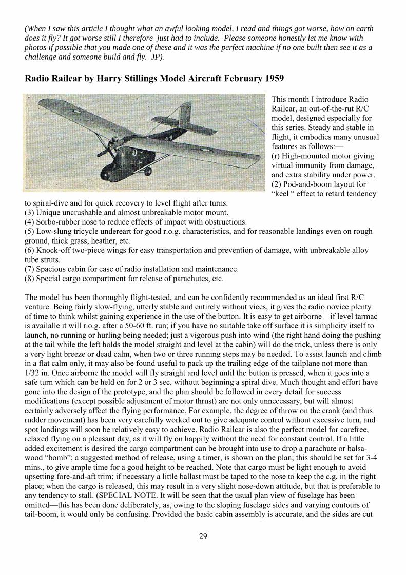
(When I saw this article I thought what an awful looking model, I read and things got worse, how on earth
does it fly? It got worse still I therefore just had to include. Please someone honestly let me know with
photos if possible that you made one of these and it was the perfect machine if no one built then see it as a
challenge and someone build and fly. JP).
Radio Railcar by Harry Stillings Model Aircraft February 1959
This month I introduce Radio Railcar, an out-of-the-rut R/C model, designed especially for this series. Steady and stable in flight, it embodies many unusual features as follows:— (r) High-mounted motor giving virtual immunity from damage, and extra stability under power. (2) Pod-and-boom layout for “keel “ effect to retard tendency
to spiral-dive and for quick recovery to level flight after turns. (3) Unique uncrushable and almost unbreakable motor mount. (4) Sorbo-rubber nose to reduce effects of impact with obstructions. (5) Low-slung tricycle undereart for good r.o.g. characteristics, and for reasonable landings even on rough ground, thick grass, heather, etc. (6) Knock-off two-piece wings for easy transportation and prevention of damage, with unbreakable alloy tube struts. (7) Spacious cabin for ease of radio installation and maintenance. (8) Special cargo compartment for release of parachutes, etc. The model has been thoroughly flight-tested, and can be confidently recommended as an ideal first R/C venture. Being fairly slow-flying, utterly stable and entirely without vices, it gives the radio novice plenty of time to think whilst gaining experience in the use of the button. It is easy to get airborne—if level tarmac is availalle it will r.o.g. after a 50-60 ft. run; if you have no suitable take off surface it is simplicity itself to launch, no running or hurling being needed; just a vigorous push into wind (the right hand doing the pushing at the tail while the left holds the model straight and level at the cabin) will do the trick, unless there is only a very light breeze or dead calm, when two or three running steps may be needed. To assist launch and climb in a flat calm only, it may also be found useful to pack up the trailing edge of the tailplane not more than 1/32 in. Once airborne the model will fly straight and level until the button is pressed, when it goes into a safe turn which can be held on for 2 or 3 sec. without beginning a spiral dive. Much thought and effort have gone into the design of the prototype, and the plan should be followed in every detail for success modifications (except possible adjustment of motor thrust) are not only unnecessary, but will almost certainly adversely affect the flying performance. For example, the degree of throw on the crank (and thus rudder movement) has been very carefully worked out to give adequate control without excessive turn, and spot landings will soon be relatively easy to achieve. Radio Railcar is also the perfect model for carefree, relaxed flying on a pleasant day, as it will fly on happily without the need for constant control. If a little added excitement is desired the cargo compartment can be brought into use to drop a parachute or balsa- wood “bomb”; a suggested method of release, using a timer, is shown on the plan; this should be set for 3-4 mins., to give ample time for a good height to be reached. Note that cargo must be light enough to avoid upsetting fore-and-aft trim; if necessary a little ballast must be taped to the nose to keep the c.g. in the right place; when the cargo is released, this may result in a very slight nose-down attitude, but that is preferable to any tendency to stall. (SPECIAL NOTE. It will be seen that the usual plan view of fuselage has been omitted—this has been done deliberately, as, owing to the sloping fuselage sides and varying contours of tail-boom, it would only be confusing. Provided the basic cabin assembly is accurate, and the sides are cut

30
exactly to plan, the fuselage must “come right” when the tail ends are drawn together. All necessary guidance is given in elevation and detail drawings.) Construction is quite straightfor ward, but all joints must be pre cemented throughout, as this adds greatly to the inherent strength. Start by building the cabin frame work—floor, ceiling, and formers A and B (note especially that the chamfer of the floor sides is added to the 4 in. wide sheet, by cementing a strip of 1/16 x 1/2 in. each side, and chamfering when thoroughly set; the 1/16in. strip serves as an accurate guide when chamfering to the correct angle, although this is not,of course, its main purpose). Make sure the formers are perfectly vertical by testing with a set-square, and then pin and rubber band the framework assembly and put aside to set really hard, as it is the basis for all other construction. Meanwhile, cut out two sides from 3/16 in. medium sheet, butting together 4 in. wide stock as necessary to achieve the required depth at the cabin; cut out the tail-boom portholes, but do not cut out the cabin doors and portholes yet—this is done later. Securely cement the two sides to the main framework, and again pin, etc., and set aside to harden. In these intervals of waiting for the cement to set, cut out the wing and tail ribs to save time later. When satisfied that the assembly so far is quite set, draw the tail ends together with the sternpost sandwiched between, cement, pin, and band in place. Now carefully bend (with the hands only to avoid pinching) a suitable length of 16 g. alloy tubing (1/4 in. inside diameter) into a long “U” shape as per plan. Tap a length of 4 in. dowel right down into each leg of the “U,” and trim the whole component to the required length. Slide into position on top of the cabin ceiling (and levelling wedge) and between over hanging tops of sides, then bed in firmly with 3/8 in. sheet, plastic wood and cement. Fit centre-section dowels and cross-pieces then fill in with sheet or block above the engine mount, trimming flush with tops of sides. Finally, sheet over with 1/8 in. sheet. Cut out the doors with a bevel cut, using a really sharp and pointed balsa knife; mark and cut out the port holes and cement acetate sheet inside—also do this now for the rear portholes to avoid forgetting it. Next sheet in the bottom only of the tail-boo m, and add the ½ x 3/16 in. cross-member at the top front of the tail-bay. Fit the tail-plane dowels, and then carefully install the entire actuator assembly (hook, motor, actuator, crank tinplate bearing), ensuring a dead-straight drive right through from the front hook to the crank bearing at the tail. Remember to drill the crank bearing slightly over size to prevent binding. Take special care to reproduce exactly the bend in the crank, as this determines the amount of rudder movement. Solder two 24 in. lengths of PVC-covered wire to the actuator contacts and fit these neatly along inside of the tailboom, taking them through into the cabin for connecting up later. Now cover the top with –j1/16in. sheet (grain crosswise), fitting the actuator hatch (note slot for cross-arm which protrudes slightly) and saddle-catch for same. Ordinary white tape is used for hinges throughout. Next fit the ½ x 3/16 in. cabin strengthencrs/door stops, but do not fit doors yet. Fit the ¼ in. stub dowels, angled as shown, for strut location (protrude 1/4in. from sides) and the tin-plate reinforcement. Make the rear undercarriage assembly and bolt to cabin floor, using metal plates on the inside, then make the cargo compartment and door. Solder up the fuel tank from tinplate and fit as shown, and add the receiver-suspension hooks and battery-pack hooks. Details of radio installation will vary according to the equipment chosen, but all necessary switches, sockets, potentiometer, etc., should now be installed. When all the work inside the cabin has been completed, fit doors and turn-buttons. This completes the major portion of the fuselage construction, and the front wheel can now be installed as per plan; then cover the top of the wheel-bay with 1/2 in. sheet and add the 1/2 in. sheet front pieces. Shape (from 1 in. sheet) and cement in place the front cabin fairing. The nose-cone assembly is made up from two laminations of 2 x 3 in. block, with 1/2 in. sheet sandwiched between; a small extra wedge of block being added to the underside to make up the necessary depth. Final shaping and sanding of the fuselage can now be done, rounding-off all edges. The rubber nose is merely half of an unburstable ball, purchased from Woolworths at about Is. 2d.—cut very carefully in half at the seam, using a razor saw—use plenty of cement and pin in position until set. Drill the motor mounting holes generously oversize to allow for possible thrust adjustments—2 to 4 deg. right thrust will be needed. Now proceed with the wings, tailplane and fin—construction of these is clear from the plan, the only points needing special mention being: (i) Make sure that the rudder loop is made exactly as shown on the plan, as this affects amount of rudder movement and thus flight characteristics.
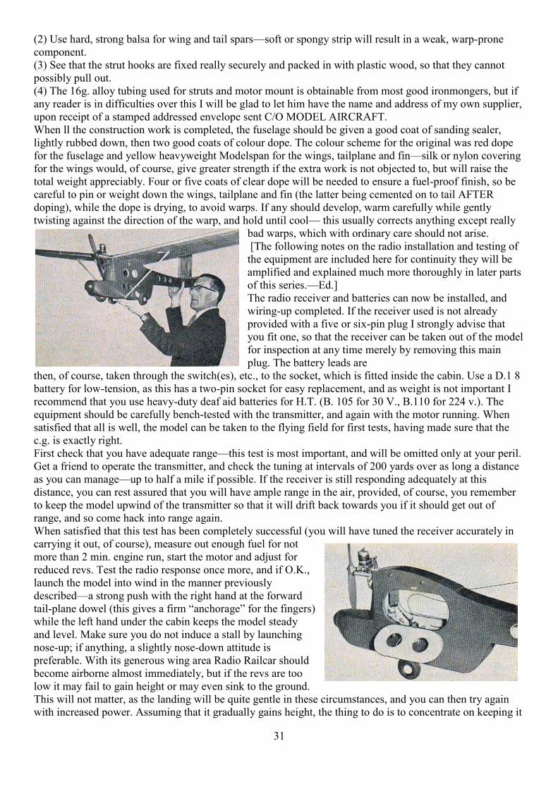
31
(2) Use hard, strong balsa for wing and tail spars—soft or spongy strip will result in a weak, warp-prone component. (3) See that the strut hooks are fixed really securely and packed in with plastic wood, so that they cannot possibly pull out. (4) The 16g. alloy tubing used for struts and motor mount is obtainable from most good ironmongers, but if any reader is in difficulties over this I will be glad to let him have the name and address of my own supplier, upon receipt of a stamped addressed envelope sent C/O MODEL AIRCRAFT. When ll the construction work is completed, the fuselage should be given a good coat of sanding sealer, lightly rubbed down, then two good coats of colour dope. The colour scheme for the original was red dope for the fuselage and yellow heavyweight Modelspan for the wings, tailplane and fin—silk or nylon covering for the wings would, of course, give greater strength if the extra work is not objected to, but will raise the total weight appreciably. Four or five coats of clear dope will be needed to ensure a fuel-proof finish, so be careful to pin or weight down the wings, tailplane and fin (the latter being cemented on to tail AFTER doping), while the dope is drying, to avoid warps. If any should develop, warm carefully while gently twisting against the direction of the warp, and hold until cool— this usually corrects anything except really
bad warps, which with ordinary care should not arise. [The following notes on the radio installation and testing of the equipment are included here for continuity they will be amplified and explained much more thoroughly in later parts of this series.—Ed.] The radio receiver and batteries can now be installed, and wiring-up completed. If the receiver used is not already provided with a five or six-pin plug I strongly advise that you fit one, so that the receiver can be taken out of the model for inspection at any time merely by removing this main plug. The battery leads are
then, of course, taken through the switch(es), etc., to the socket, which is fitted inside the cabin. Use a D.1 8 battery for low-tension, as this has a two-pin socket for easy replacement, and as weight is not important I recommend that you use heavy-duty deaf aid batteries for H.T. (B. 105 for 30 V., B.110 for 224 v.). The equipment should be carefully bench-tested with the transmitter, and again with the motor running. When satisfied that all is well, the model can be taken to the flying field for first tests, having made sure that the c.g. is exactly right. First check that you have adequate range—this test is most important, and will be omitted only at your peril. Get a friend to operate the transmitter, and check the tuning at intervals of 200 yards over as long a distance as you can manage—up to half a mile if possible. If the receiver is still responding adequately at this distance, you can rest assured that you will have ample range in the air, provided, of course, you remember to keep the model upwind of the transmitter so that it will drift back towards you if it should get out of range, and so come hack into range again. When satisfied that this test has been completely successful (you will have tuned the receiver accurately in carrying it out, of course), measure out enough fuel for not more than 2 min. engine run, start the motor and adjust for reduced revs. Test the radio response once more, and if O.K., launch the model into wind in the manner previously described—a strong push with the right hand at the forward tail-plane dowel (this gives a firm “anchorage” for the fingers) while the left hand under the cabin keeps the model steady and level. Make sure you do not induce a stall by launching nose-up; if anything, a slightly nose-down attitude is preferable. With its generous wing area Radio Railcar should become airborne almost immediately, but if the revs are too low it may fail to gain height or may even sink to the ground. This will not matter, as the landing will be quite gentle in these circumstances, and you can then try again with increased power. Assuming that it gradually gains height, the thing to do is to concentrate on keeping it
32
into wind, only attempting a turn when it is at least 30-40 ft. up; even then you must be careful not to hold on the button too long—come around in a series of quarter-turns, pausing to allow the inner wing to rise, then blipping through the unwanted rudder position and holding down for another quarter-turn. In this way you will eventually have completed a full circle and be facing back into wind again. With the short motor-run the engine may now cut, but do not worry about trying to get back for a spot-landing. This will come later when these first flight-tests have been successfully concluded. Concentrate on keeping the model into wind; watch the glide carefully, noting if it is straight on neutral and fairly flat, and, if not, make a mental note of the deviations for correction later. When you’ve got the model safely down again, make any necessary adjustments a little at a time ! It’s better to have a dozen short test flights, gradually getting the trim exactly right, than to bang on a load of trim-tab or a great wad of packing, only to see the model completely out of control. If the power-on neutral flight path is more than a very little off straight (a tendency to bear very slightly left on neutral, for instance, can often be an advantage), correct this by adjustment of thrust only—do not use the trim tab, otherwise you will throw out the glide path.This is why the bolt-holes in the motor mount are drilled generously over-size, to allow for such adjustments, as different motors and props will affect the degree of torque reaction. Having successfully surmounted these initial flight tests (always the most crucial and perilous phase in the life of any model) you can use full power and increase the motor-run to, say, 5 min. which will give enough time for the model to gain a good height and so permit longer and more detailed study of flight performance both under power and on the glide: final optimum adjustments can then he made, when the model should continue to perform reliably for an indefinite period, provided no changes are made in motor, prop, c.g., etc., and flying surfaces are maintained true and free from warps. Experience in control can now be built up, but remember to make haste slowly and fly with care and common-sense. For instance, do not jeopardise the model (and risk injury or damage) by trying to make spot- landings under impossible conditions, such as when the final approach would take it directly towards obstructions such as trees, cars, or spectators. In such circumstances, be content to get it down safety in a safe place, even if it means a walk of several hundred yards to retrieve it. Similarly, don’t try to weave intricate patterns in the sky until you have become thoroughly familiar with the model’s characteristics, so that you know exactly when to press and (more important!) when to let go of the button. Every model has its own peculiarities, even when ostensibly identical in every respect with another, and the way to a long and honourable model life is to get to know your own aircraft inside-out so that eventually you have the feeling that you are actually up there in it, and know precisely what effect the next signal will have, and exactly when to give the command. Radio Railcar is not a stunt model and was never intended as such, so don’t try hair-raising spiral dives to within inches of the ground, or similar manoeuvres. When you feel you are ready for such goings-on, build another model designed for that purpose (such as my acrobatic design Zoom, M.A. Plan No. 252) which will give you all the thrills you want. Radio Railcar will not only help you safely and painlessly through your R/C apprenticeship, it is also a model to which you will be glad to return again and again for relaxed, restful flying, especially after a period of frantic button-bashing with some misguided missile of more flashy performance! If you start building Radie Railcar now you will have partially completed it in readiness for the next article in this series, which will deal with bench-testing of your radio equipment and familiarising yourself with the various functions befor installing it in the model. From Dave Bishop of DB Sound There was a good send-off for "our Elvis" when some 30 plus people attended the funeral of Colin Agate at the North East Surrey's Crematorium on February 6. It wasn't a religious affair and the person who conducted the ceremony was a neighbour and Colins landlord, Steve Middleton. It all started with the music being played of Elvis Pressley singing "Glory Alleluia" and then Mr Middleton said that Colin had been a very successful racing motor cyclist. Some of those racing colleagues were there who were with him in those days one of those being a London Fire officer. The attendees were told that he had been a member of a spiritualist church. Tributes were paid by David Horton about their school days together when they went to

33
Epsom downs flying their combat models. He also loved animals and he was a very compassionate man. Further tributes were made by Ken Sheppard who runs the 3 annual Modelair events at Old Warden each year. It was at that event that Colin won the Shuttelworth Trophy scale event no less than 6 times. It was after that final record number of wins that Colin was asked to be a judge and it was a job that he enjoyed and did well. Colin disappeared from us all when the curtain surrounded him to the moving Country and Western song, "Remember When". The attached pictures on my computer's hard drive all taken over the years from many shows at airfields in this, and other countries.
Ken Sheppard retired editor of RC Model Flyer The two scale judges at the K2 Arena at Crawley magazine with the 6 times winning award given to BMFA indoor flying meeting on February 8 - 2010 Colin Agate at Old Warden. In the background is are (left) Colin Agate and Don Coe. This years school pal David Horton. annual event will be at the same venue on Sunday March 8 -2015 from 11am till 6pm. Post code RH11 9BQ
Trophies on show at Colin Agates funeral on February 6, included those from his winning racing motor cycling days at the Isle of Man and others were won at aeroplane events.

34
16 flyers flew together at last year's special WW1 - 100th anniversary Modelair event at Old Warden from an idea by Mike Reynolds.
A large pre-war German glider was towed up A Scale winner at Old Warden in 2014 to a great height at Old Warden's Modelair event in 2014.
A nice new "biggee" prototype kit from the popular Sport & Scale manufacturer at Old Warden where most good kit's appear for the massive attendees to see and buy.
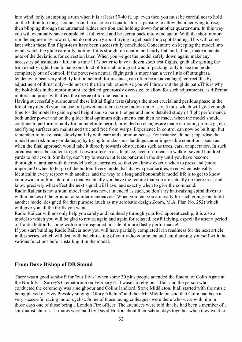
35
A trio of WW1 aeroplanes with a Fokker -SE5 and a Nieuport between flights at Old Warden's Modelair show in 2014.
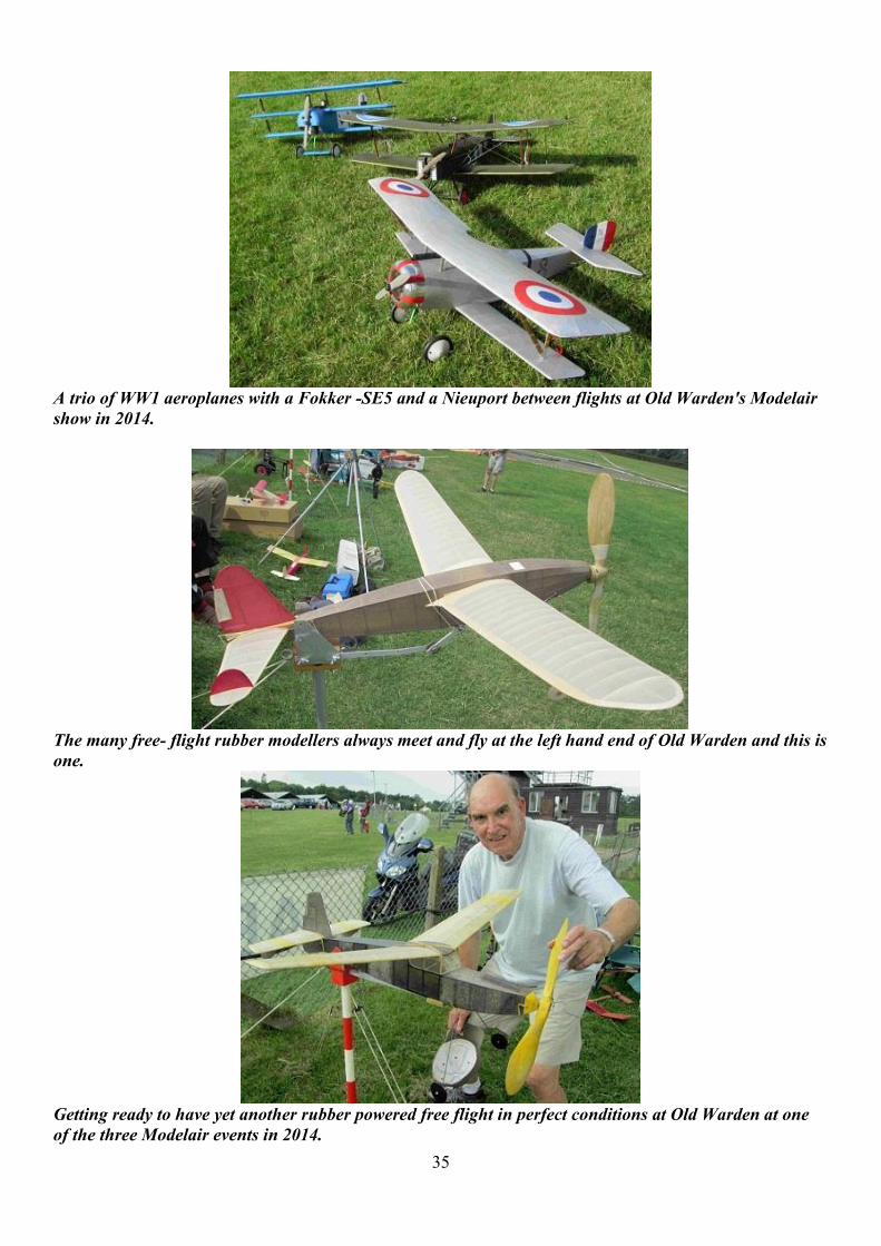
The many free- flight rubber modellers always meet and fly at the left hand end of Old Warden and this is one.
Getting ready to have yet another rubber powered free flight in perfect conditions at Old Warden at one of the three Modelair events in 2014.
36
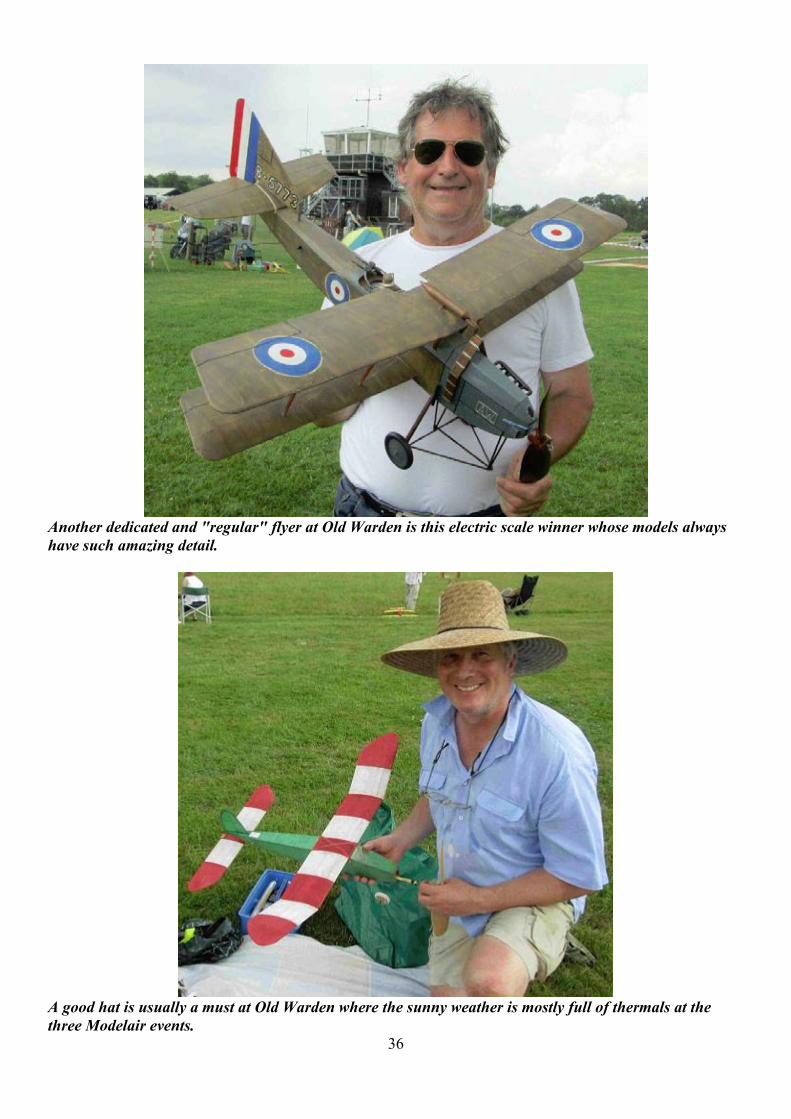
Another dedicated and "regular" flyer at Old Warden is this electric scale winner whose models always have such amazing detail.
A good hat is usually a must at Old Warden where the sunny weather is mostly full of thermals at the three Modelair events.

37
Another free flight model at Old Warden in 2014 this one is electric powered.
A lovely friendly man with his home built rotary engine at Old Warden which, when it was running, sounded just like a ticking clock.
Another "must go to" airfield is at Manchester which has superb viewing areas and excellent restaurant and children's play area. They have built a huge new hanger for a tour of a Concorde with special "those who flew in them" speakers - totally riveting!

38
A Mitchell bomber was one of the many German built aeroplanes at Weston Park show held over the Fathers day weekend in 2014 always run by Steve Bishop.
The team of Dutch pulse jets who stopped the show at Weston Park last year held over the Fathers Day weekend. The two related pilots were age 28 and 13 years old.

39
How times Change then and now
MkI Cortina getting ready for a rallye Early 70’s
Ace of Diamonds getting ready for a kip, 2015

40
David Kinsella’s Column Great Alexander Here’s a fine snap of Sam Alexander with three of his several VTRs. In fact the Mercury Mk I in his hands is the one he kindly built for me and saw to ist delivery all the way from Scotland. Frog 500 powered with Boy’s Own in bold lettering on the starboard wing, there’s much of the classic racer in this Class B from Henry J and his famous shop on Holloway Road. Also seen is a Cardinal Puff (ED 346) and a swift Lazy Daisy (Enya 29). Like me a keen enthusiast of Ken Bedford’s wares, Sam’s envelopes sport an ETA Superpowered logo. President of America’s SCCA, Fred Wacker decorated his stationery with his famous red Allard, the Cadillac-powered 8-Ball. A heart surgeon chum on the West Goast does likewise. Let the deed show! Billy Bishop With 72 victories to his credit, the Great War ace flew Nieuport 17 and SE5a fighter scouts, won the VC and a clutch of other awards, operated his own flying service with William Barker, lost it all in the 1929 crash and died in Florida in 1956 at iust 62. Winged Warfare and Winged Peace were his books and he starred in Hollywood’s Captains of the Clouds. Why not model his SE5a for the coming season? Another New Engine With plate frames cut and all wheels cast and machined, a brand new express of the LNER is taking shape in Darlington. Gresley’s Cock O’The North the first of the line (and named after a Scots aristocrat) and able to haul 700 ton trains in the hilly conditions to Aberdeen, the new 2-8-2 follows brand new Tornado and its great success on the lines. The French masters of serious steam power with their test plant at Vitry, Gresley knew Chapelon and de Caso and took engines for testing in France. Car-type valves will be a feature of the new engine to be known as Prince of Wales. Tab Meister Stars command millions - but many need it. One famous name who was married to another famous name had a personal staff of 47! One received an extra £25 thousand to clear a housing debt. Private jets and yachts and floors at the Ritz require powerful funding. Mite Matters Brian Lever’s inspired celebration of the Phantom Mite saw several turni up with plans, articles, kit boxes and ancient fuel bottles and cans. With the dash of the Spitfire about her, the Mite is a fine little aeroplane an age of history to match. Hundreds and hundreds more built over the years as good chaps came to power for the first time, it would be good to show a few of those early efforts in S&T. What have you? Watches Quality clockwork watches are a joy and an investment. The Telegraph run a special section from time to time, most recently a super 28—pager on the best in the buisness. Some of us have the early Rolex GMT Master in blue and red, sometimes called the Pepsi and dating from 1955 when airline pilots were pictured wearing them. At the top of the tree these days is the stunning Grandmaster Chime of 1580 parts and 20 complications and selling for £2 million. But still there is the Mega 4 with 36 complications from Franck Muller although price and availability are unknown. Mostly worn on the wrist these days, we remember The Thomas Crown Affair and MacQueen’s pocket watch in his Doug Hayward three-piece. The 1914-18 conflict boosted the wrist watch.
41
Model Boats Veloce published 145 big pages on the Vintage scene, manufacturers including Hornby, Bowman, Penguin, Sutcliffe and others well covered. There’s heaps of pictures and text, author Roger Gillham an enthusiast from boyhood. A rare Bowman Club badge always helps things along. Our Vic Smeed was a great model boat enthusiast, the Spitfire pilot several years ago selling me a selectìon of his own including a huge one almost as lang as my bath. Among them too was a Roger Stollery Marblehead in fine veneers called Lazy Devil. Complete with measuring certificate, she slips along on a mere breath of wind as sunshine glances off perfect varnish. Steam Chums admiring my Christmas card still may wonder about the mighty exhaust from GWR King Henry VII. Fear Not! Snow indicates that it’s a very cold day and hot steam and smoke hitting the chill air has that effect captured so well by top hole artist Eric Boattomley GRA. Rest assured that another corker is ready for Christmas 2015. A Touch Provocative Mick Jagger’s idea way back in 1971, the famous logo seen around the world was drawn by John Pasche when a student at the Royal College of Art. These days it’s seen on the face of Swiss Zenith watches and at all rock concerts worthy of the name. On show in London in December, it’s a possible for wing decoration at some time. Island Bound Captain Eric Wirikle Brown was on Desert Island Discs in November, no doubt amazing many with his exploits and news of his new sports car. Discs chosen included Glen Miller (he knew him), Rod Stewart and Arty Shaw. A dozen log books list 487 types flown and 2407 carrier landings. Udet urged him to learn modern languages and train as a pilot having taken him up for a spin in Berlin. Rosemeyer Linen wind helmet days of yore, centre lock wire wheels too, here a Porsche-designed Auto Union tackles a turn in Monaco. Although raced in the USA, when it came to speed record attempts the cars charged the autobahn in sometimes windy conditions! Caracciola anaged it but poor Rosemeyer anthe Auto Union did not, the young ace found unmarked by a tree. Married to a record breaking pilot, a stone by the Darmstadt autobahn remebers the fun lover who enjoyed pranks and fried eggs on the tyres of his recer. Limited Edition Books and news programmes numerous trumpet the Victorians and what they did for us: railways, mass production, Empire, agriculture and more. But not much mentioned yet the key to all this was the concept of Limited Liability. £100 into a new venture and all you could loose was £100. Before the concept was accepted - and it had to be - that £100 could be followed by the loss of home and furniture and practically everything else. New York launched Limited Liability in 1811, the UK following in 1844 and fully in 1855. Great Tinp1ate An auction on television saw a model P2 Alfa Romeo in distressed condition go for £2500. Rare now, vital parts missing when found, a full restoration will add thousands. The P2 was driven by Nuvolari, Guidotti and Campari, the upholstered drinks heir bursting into song when crowds cheered him on. Our Mike Crisp can handle any tinplate project should a battered boat or car come your way and here I write from experience.

42
Sir Mick’s Flick The Stone’s latest movie celebrates the life of fellow rock star James Brown, the lad zooming from poverty to the world stage of R&B via blistering live acts and his Live At The Apollo album. Relegated to support the Rolling Stones in Santa Monica and so annoyed, Brown pulled out all the stops and gave the performance of his life before a huge and astonished crowd. Still remembered after fifty years.... Event dates Wimborne MAC (Between Blandford Forum and Salisbury) 12 April Sunday Control line day, grass circles, BBQ, portaloo, weather will be perfect 11 October Control line day, grass circles, BBQ, portaloo, weather will be perfect as in April More info from [email protected] http://wimbornemac.org/ DMFG Near Blandford Forum 19 April Sunday 36” glider and Ebeneezers Subject to weather. See http://www.wessexaml.co.uk/homes36ffgliders.html 10 May Sunday R/C vintage, 36” glider CL & nat Tomboy 23 May Saturday 36” glider and Ebeneezers 30 May Saturday Scale + Vintage 20 June Saturday 36” glider and Ebeneezers More information on above events [email protected] Machrihanish Hello everyone, Just to let you know that the spring fun fly at Machrihanish will be held on the first weekend of May, the 1st-2nd-3rd. I would ask all who intend to support this event to get their details in to myself or Andy Rudden by the last week of April. To maintain our presence at this wonderful site,you support is essential,so please spread the word ,and don't forget we fly anything,rubber power to pulse jets! Bryan Passey [email protected] Shilton Just the dates for the Shilton vintage event this year they are Saterday 23rd and Sunday the 24th of May and Saterday 12th and Sunday the 13th of September contacts Nick Blackwell and me same emails and phone as last year [email protected] phone 01285 657610

43
Cocklebarrow The dates for Cocklebarrow are as follows: 12th July, 23rd August and 4th October.
This year’s event will be held on the weekend of 15th and 16th August. Format for the event will be very similar to previous years with :
Off the peg flying both days Camping facilities (please contact us to book in advance) Saturday night BBQ Onsite toilets and drinking water facilities 200 ft grass strip for R/C flight Control Line Circle (depending on availability of land as we are on a working farm) Small field Free flight Bring and Buy Sale - bring along your bits that are "Surplus to Requirement" and turn them into cash
This years mass build event will be celebrating the designs of David Boddington. If you have any of his designs in your hangar then bring them along - if not then why not build one and maiden it at the gathering. For more information and to book your entry in early please email -
It goes without saying but please :-
WILL ALL PILOTS PLEASE ENSURE THAT THEY HAVE PROOF OF VALID INSURANCE WHEN BOOKING IN

44
FLYING NORTH A goldmine for vintage and
nostalgia model flyers – FLYING NORTH traces the model flying career of Jack North, one of only two people to represent the UK in on all three outdoor free flight teams, - Wakefield, Power and Glider. It covers his flying and models from 1938 onwards and includes no less than 24 of his previously-unpublished designs. FLYING NORTH was compiled and edited by two of Jack’s Croydon clubmates, David Beales and Martin Dilly, who had access to Jack’s extensive notebooks, photographs, drawings and his original models. FLYING NORTH is a fascinating 163 page book and includes 130 photographs, reminiscences by colleagues, re-prints of all Jack’s published plans and articles, including his later extensive work on thermal detection, and an outline of the professional career that also made him such a re spected name ¡n high-speed aerodynamics. FLYING NORTH proceeds go towards the costs of the national teams representing the UK at World and European Free-Flight Championships.
Price £18 in the UK, £20 airmail to Europe and £22 elsewhere. Contact Martin Dilly on +44 (0)208-7775533 or email [email protected]

45
INDOOR MODEL FLYING
FREE FLIGHT ONLY
TUSEDAY 24th MARCH TUSEDAY 28th APRIL
7pm to 10pm
ALLENDALE CENTRE HANHAM RD. WIMBORNE BH21 1AS
FREE CAR PARKING IN PUBLIC CAR PARK IN ALLENDALE RD
COMPETITIONS incl GYMINNIE CRICKET LEAGUE ALL FLYERS MUST HAVE BMFA INSURANCE
FLITEHOOK NORMALLY IN ATTENDANCE Adult Flyers £5 Spectators £1.50
CONTACTS:JOHN TAYLOR
Flitehook Indoor meetings at Totton - Southampton Sunday 8th March 2015 Flitehook Indoor Free Flight Meeting, Totton Community Centre, Hazelfarm Road, Totton, Southampton, SO40 8WU. 10.00a.m. to 4.00p.m. Contact Flitehook Tel. No. 02380 861541

46
Kits and Cox 049 Engines from under £20…CL Cox 049 Starter Package £60….Great value, high quality Glow Plugs from Merlin….hard to find CL accessories at sensible prices…..E – Zee Mk3
Electric Control Line Timer - sole stockist
On Line shop at www.densmodelsupplies.co.uk Or phone Den on 01983 294182 for traditional service