stereotactic imaging in functional neurosurgery...
TRANSCRIPT

i
UMEÅ UNIVERSITY MEDICAL DISSERTATIONS New series No. 1462
STEREOTACTIC IMAGING IN FUNCTIONAL NEUROSURGERY
Hidehiro Hirabayashi
From the Department of Pharmacology and Clinical Neuroscience, Neurosurgery Umeå University, Umeå, 2012

ii
Responsible publisher under Swedish law: the Dean of the Medical Faculty This work is protected by the Swedish Copyright Legislation (Act 1960:729)
Copyright © 2012 by Hidehiro Hirabayashi ISSN 0346-6612
ISBN 978-91-7459-325-9 Electronic version: http://umu.diva-portal.org/ Printed by Print & Media, Umeå University
Umeå, Sweden 2012
iii
“In clinical practice, brain imaging can now be divided in two
parts: the diagnostic neuroradiology and the preoperative stereotactic localisation procedure. The latter is part of the therapeutic procedure. It is the surgeon’s responsibility and
should be closely integrated with the operation.”
Lars Leksell (1907 –†1986), 1985
“Seeing is believing”

iv

v
STEREOTACTIC IMAGING IN FUNCTIONAL NEUROSURGERY
Hidehiro Hirabayashi Department of Pharmacology and Clinical Neuroscience, section of Neurosurgery
ABSTRACT
Background The birth of stereotactic functional neurosurgery in 1947 was to a great extent dependent on the development of ventriculography. The last decades have witnessed a renaissance of functional stereotactic neurosurgery in the treatment of patients with movement disorders. Initially, these procedures were largely based on the same imaging technique that had been used since the birth of this technique, and that is still used in some centres. The introduction of new imaging modalities such as Computed Tomography (CT) and Magnetic Resonance Imaging (MRI) provided new potentials, but also new challenges for accurate identification and visualisation of the targets in the basal ganglia and the thalamus with an urge to thoroughly evaluate and optimize the stereotactic targeting technique, as well as evaluate accurately in stereotactic space the location and extent of stereotactic Radiofrequency (RF) lesions and the exact position of deep brain stimulation (DBS) electrodes. Aims To study the differences between CT and MRI regarding indirect atlas coordinates in thalamic and pallidal procedures and to evaluate and validate visualisation of the pallidum and the subthalamic nucleus in view of direct targeting irrespective of atlas-derived coordinates. Furthermore, to evaluate the contribution of various RF parameters to the size of stereotactic lesions, as well as the impact of size and location on clinical outcome. Method The surgical coordinates defined in relation to the landmarks of the 3rd ventricle, of the targets in the pallidum and ventrolateral thalamus were compared between CT and MRI in 34 patients. In another 48 other patients direct visualization of the pallidum was evaluated and compared to indirect atlas based targeting. The possibility and versatility of visualizing the subthalamic nucleus (STN) on short acquisition T2-weighted MRI were evaluated in a multicentre study, and the use of alternative anatomical landmarks in identification of the STN was demonstrated in another study. In 46 patients CT and MRI were compared with respect to the volume of the visible RF lesions in the thalamus and the pallidum. The volume was analysed with regard to the parameters of the RF coagulation. The location and size of the lesions were further evaluated in relation to clinical outcome. Results Minor deviations, mostly frame dependent, were seen between MRI and CT coordinates of brain targets. The rostro-caudal direction of these deviations were such that they would be easily accounted for during surgery. MRI using a proton density sequence provided detailed images of the pallidal structures, which demonstrated considerable inter-individual variations in relation to the landmarks of the 3rd ventricle. By using a direct visualization of the target, each patient will act as his or her own atlas, avoiding the uncertainties of atlas-based targeting. The STN could be visualized on various brands of MRI machines in 8 centres in 6 countries with good discrimination and with a short acquisition time, allowing direct visual targeting. The same scanning technique could be used for postoperative localization of the implanted electrodes. In cases where the lateral and inferior borders of the STN cannot be easily distinguished on MRI, the Sukeroku sign and the dent internal-capsule-sign signs might be useful. The volume of a stereotactic RF lesion could be as accurately assessed by CT as by MRI. The lesion´s size was most strongly influenced by the temperature of coagulation. The lesions´ volumes were however rather scattered and difficult to predict in the individual patient based solely on the RF coagulation parameters. For thalamotomy, the results on tremor was not related to the lesion´s volume. For pallidotomy, larger and more posterior-ventral lesions had better effect on akinesia while effects on tremor and dyskinesias were not related to size or location of the lesions.. Conclusions The minor deviations of MRI from CT coordinates can be accounted for during surgery, why MRI can obviate the need of CT in some procedures. Direct visualized targeting on MRI of the pallidum is superior to atlas based targeting. The targets in the pallidum and the STN, as well as the location of the electrodes, can be well visualized with short acquisition MRI. When borders of the STN are poorly defined on MRI the Sukeroku sign and the dent internal-capsule-sign signs proved to be useful. The volumes of RF lesions can be accurately assessed by both stereotactic thin slice CT and MRI. The size of these lesions is most strongly influenced by the temperature of coagulation, but difficult to predict in the individual patient based on the coagulation parameters. Within certain limits, there were no clear relationships between lesions´ volume and location and clinical effects of thalamotomies and pallidotomies. Keywords: Deep brain stimulation, pallidotomy, thalamotomy, Parkinson’s disease, Essential tremor, CT, MRI.
vi
PUBLICATIONS AND MANUSCRIPTS This thesis is based on the following publications and manuscripts, which are referred to in the text by their Roman numerals: I. Comparison between stereotactic CT and MRI coordinates of pallidal and thalamic
targets using the Laitinen noninvasive stereoadapter. Hirabayashi H, Hariz MI, Fagerlund M. Stereotact Funct Neurosurg. 1998;71(3):117-30
II. Stereotactic imaging of the pallidal target. Hirabayashi H, Tengvar M, Hariz MI. Mov
Disord. 2002;17 Suppl 3:S130-4. III. A quick and universal method for stereotactic visualization of the subthalamic nucleus
before and after implantation of deep brain stimulation electrodes. Hariz MI, Krack P, Melvill R, Jorgensen JV, Hamel W, Hirabayashi H, Lenders M, Wesslen N, Tengvar M, Yousry TA. Stereotact Funct Neurosurg. 2003;80(1-4):96-101.
IV. "Sukeroku sign" and "dent internal-capsule sign"--identification guide for targeting the
subthalamic nucleus for placement of deep brain stimulation electrodes. Taoka T, Hirabayashi H, Nakagawa H, Sakamoto M, Kitano S, Takahama J, Marugami N, Takayama K, Akashi T, Miyasaka T, Iwasaki S, Kurita N, Sakaki T, Kichikawa K. Neuroradiology. 2009;51(1):11-6.
V. Is there a relationship between size and site of the stereotactic lesion and symptomatic
results of pallidotomy and thalamotomy? Hariz MI, Hirabayashi H. Stereotact Funct Neurosurg. 1997;69(1-4 Pt 2):28-45.
VI. Impact of parameters of radiofrequency coagulation on volume of stereotactic lesion in
pallidotomy and thalamotomy. Hirabayashi H, Hariz M, Wårdell K, Blomstedt P. Stereotact Funct Neurosurg. In press.

vii
CONTENTS
ABSTRACT............................................................................................................ v
PUBLICATIONS AND MANUSCRIPTS........................................................... vi
CONTENTS............................................................................................................ vii
ABBREVIATIONS................................................................................................ viii
INTRODUCTION.................................................................................................. 1
BACKGROUND OF THE PRESENT STUDY.................................................. 7
AIMS....................................................................................................................... 10
MATERIALS AND METHODS........................................................................... 11
SURGICAL TECHNIQUE................................................................................... 16
STATISTICS.......................................................................................................... 17
RESULTS................................................................................................................ 18
DISCUSSION......................................................................................................... 30
GENERAL SUMMARY........................................................................................ 36
CONCLUSIONS.................................................................................................... 37
ACKNOWLEDGMENTS..................................................................................... 38
REFERENCES...................................................................................................... 39
ORIGINAL PAPERS I – VI Paper I: Comparison between stereotactic CT and MRI coordinates of pallidal and
thalamic targets using the Laitinen noninvasive stereoadapter Paper II: Stereotactic imaging of the pallidal target Paper III: A quick and universal method for stereotactic visualization of the subthalamic
nucleus before and after implantation of deep brain stimulation electrodes Paper IV: "Sukeroku sign" and "dent internal-capsule sign"--identification guide for
targeting the subthalamic nucleus for placement of deep brain stimulation electrodes
Paper V: Is there a relationship between size and site of the stereotactic lesion and symptomatic results of pallidotomy and thalamotomy?
Paper VI: Impact of parameters of radiofrequency coagulation on volume of stereotactic lesion in pallidotomy and thalamotomy

viii
ABBREVIATIONS The following abbreviations are used in the text: 3-D Three-dimensional AC Anterior commissure of the third ventricle AC-PC Anterior commissure-posterior commissure line ANOVA Analysis of variance ºC Degree Celsius CRW Cosman-Robert-Wells CSF Cerebrospinal fluid CT Computed Tomography DBS Deep brain stimulation DTI Diffusion tensor imaging ET Essential tremor ETL Echo Train Length ETRS Essential tremor rating scale FM Foramina of Monro fMRI Functional MRI FoV Field of View FSE Fast spin echo GA General anaesthesia GE General Electric GP Globus pallidus GPe Globus pallidus externus Gpi Globus pallidus internus Hz Hertz IC Internal capsule ICL Intercommissural line IPG Implantable pulse-generator KHz Kilo Hertz L-dopa Levodopa LA Local anaesthesia mA Milliampere MCP Midcommissural point MER Micro-electrode recording mm Millimetre MRI Magnetic resonance imaging ms Millisecond µs Micro-second Nex Number of excitations p Probability value PC Posterior commissure of the third ventricle PD Parkinson’s disease PET Positron emission tomography PPN Pedunculopontine nucleus PVP Postero-ventral pallidotomy RF Radiofrequency s Seconds SAR Specific absorption rate

ix
SD Standard deviation SN Substantia Nigra SNR Substantia Nigra pars reticulata STIR Short tau inversion recovery STN Nucleus Subthalamicus T Tesla TE Echo time TR Repetition time UPDRS Unified Parkinson’s disease rating scale V Voltage Vim Nucleus ventralis intermedius of thalamus VL Ventrolateral thalamus X or x Coordinate for laterality Y or y Coordinate for antero-posterior direction Z or z Coordinate for dorso-ventral direction Zi Zona incerta

x

1
INTRODUCTION – EVOLUTION OF STEREOTACTIC IMAGING IN FUNCTIONAL NEUROSURGERY Functional neurosurgery is a surgical procedure to treat functional disorders of the brain such as movement disorders (Parkinson’s disease (PD), dystonia, essential tremor), as well as intractable pain, psychiatric disorder, and some forms of epilepsy. These diseases are considered due to dysfunction of specific neural structures or neuronal networks, therefore, either the ablation or stimulation of these abnormal neural structures or neuron-circuits has been historically performed. In this kind of surgery on deep brain structures, One cannot use the microscope to visualise or confirm the target, unlike surgery for tumors or vascular malformations. In the practice of functional neurosurgery, it is essential to use the stereotactic technology, in order to reach the target for implanting a probe or for lesioning. The stereotactic technique relies on a stereotactic frame and some kind of imaging to direct the probe to the brain target. Blaine S. Nashold, famous functional neurosurgeon from Duke University in Durham, North Carolina, published a paper in 1994, entitled “The history of stereotactic neurosurgery”123. Nashold began his paper by quoting the following sentence from the thesis of M. Hariz: “The history of stereotaxis is to a great deal the history of its instrument, the stereotactic frame”54. Today, one could add that the history of functional stereotaxis is to an equally great deal the history of brain imaging. In fact, if the stereotactic frame is one prerequisite for functional stereotaxis, the corollary and equally important prerequisite is brain imaging. Brain imaging has in fact and to a great extent dictated even the shape and the geometry of stereotactic frames, and even the material from which they are manufactured. Furthermore, recent advances in brain imaging modalities have provided –and continue to provide -- “new” brain targets for “new” indications and applications (more on this below). X-Rays and ventriculography In 1896, Wilhelm Konrad Röntgen introduced X-rays, and demonstrated its unlimited potentials in medicine137, 138. Already the following year, a French frame suitable for X-rays in two projections for localization of intracranial projectiles was presented11, 133. Horsley and Clark’s stereotactic frame for use in animals was presented in 190876. A frame intended for human use, but that was never used in humans, was designed by Mussen in 1918125, 131. These frames were based on the use of external landmarks19 and the visualizaion of the corpus pineale on plain x-rays. A technique allowing for further visualization of intracranial structures was not introduced untill 1918, when neurosurgeon Walter Dandy presented cerebral ventriculography using air as a contrast30. This method, still used in some centres today --albeit with both air and positive contrast agents--, was the prerequisite enabling the performance of functional stereotactic neurosurgery in humans that started at the hands of neurologist Spiegel and neurosurgeon Wycis 29 years later in 1947153. They called their new technique ‘‘stereoencephalotomy’
The demands of ventriculography-based functional stereotactic surgery have dictated the need for stereotactic frames to be made with material that is readily visible on the X-ray images, and possible to align on the head in a way that allows geometrically accurate determination of the third ventricle landmarks, and to provide well-visualization of the frame reference structures necessary to perform the surgical intervention. Parallax phenomena, magnification issues, and misalignment of frame and head in relation to the X-ray source, were addressed by designing various shapes of the stereotactic frame, by judicious placement of the x-ray sources in relation to the patient´s head and the frame attached to it, and by various ways to circumvent the pitfalls of x-ray imaging to avoid miscalculation of the target

2
coordinates106, 166. With “brain” imaging firmly established thanks to ventriculography, to the use of suitable stereotactic frames, and with the help of various atlases demonstrating the approximate position of various midbrain structures in relation to the third ventricle, functional stereotaxis experienced a tremendous popularity from the early 1950s and onwards, especially in surgical treatment of Parkinson´s disease and other movement disorders, as well as in stereotactic surgical interventions in patients with chronic pain or with epilepsy, and in psychiatric illness46.
Originally, the lesions were made with alcohol injection, which theoretically was more likely to affect the neurons in the intended nucleus while sparing the fibers en passage. The spread of the alcohol was unpredictable, however, so soon lesions were made with electrolytic direct current such as Horsley and Clarke had reported almost half a century before. Other ways to perform lesioning included the use of procaine-oil, or oil-procaine-wax injection, a balloon, a coagulating substance, mechanical damage with a leukotome, cryoprobe methods, and later on radiofrequency, which is the method that has gained worldwide acceptance15, 27, 28, 46, 118, 121, 122, 124, 157. It is estimated that by 1965 more than 25,000 functional stereotactic procedures had been done worldwide, and by 1969 the number reached 37,000 patients operated150, 151. All these procedures were performed for various functional brain disorders, with PD being the main application, and all were based on ventriculography-targeting and the use of atlases of the brain, especially atlases of the thalamus and basal ganglia.
The main legacy of ventriculography and pneumoencephalography in stereotactic surgery is the anterior commissure–posterior commissure line (AC-PC line), which became the main reference in relation to which the position of various midbrain structures were calculated, according to the Cartesian three planes of space. The two principal brain atlases relying on the AC-PC line were the Atlas of Schaltenbrand and Bailey143, an a later edition by Schaltenbrand and Wahren144 as well as the Atlas of Taliarach165. In a method based on brain atlases, the inter-individual variabilities of the position of various midbrain structures was a problem. Computed Axial Tomography The advent of computed axial tomography (CT) in the mid-1970s77 had, as we know, the most fundamental impact ever on all aspects of neurosurgery. For the first time ever, and non-invasively, the neurosurgeon could actually “see” the brain in vivo, and CT could directly visualize the different pathologies that affect the brain, from traumatic or spontaneous haemorrhages, to tumours, malformations, etc. In functional stereotactic surgery, the impact of CT was equally important even though the CT image as such could not show the subdivisions of the thalamus or other usual functional brain targets, but with later versions of the CT machines, it could show accurately the ventricular references on the basis of which the location of the functional target could be calculated61. Despite the failure of CT to directly visualise a functional target, the advent of the CT scan forced the re-design of both the geometry of the stereotactic frame and of the material from which it is made: while the X-ray-ventriculography method provided frontal and lateral projections, the CT provided axial (horizontal) scans, i.e. axial images of head and brain. This axial image could provide the anteroposterior and lateral coordinates of a given brain target, but the vertical coordinate was obviously difficult to evaluate. It was a graduate student at the University of Utah who solved that problem of the Z (verical) coordinate by introducing the clever oblique bar to a localizing box attached to the stereotactic frame. The stereotactic frame with the localization box incorporating ”N” or “Z” shaped fiducials became standard for all CT-guided (and later on MRI-guided) stereotactic procedures, including functional and morphological procedures 67. The N or Z shaped fiducials allowed to calculate the vertical position of a target by

3
assessing and measuring on a single axial scan the distance between the three points of the Z or N shaped structures, these distances being different on different scans along the superior-inferior direction, depending on the “depth” of the scanned brain area. Hence, with these innovative modifications, a single axial scan at the level of the brain target did indeed contain all necessary information in terms of X, Y, Z coordinates of that target. Furthermore, the advent of CT forced a new denomination of the X-Y-Z coordinates of the stereotactic target: the anteroposterior direction became Y instead of the previous X, the dorso-ventral became Z instead of Y and the lateral direction became X instead of Z. Additionally, in order to accommodate for the disturbing metal artefacts of previous stereotactic frames, these had to be re-designed in a material that showed as little as possible artefacts on the CT image while still being fully visible as reference fiducials on that image. In some instances, new CT compatible “interfaces” between CT and frame were designed to circumvent the metallic disturbances of the frame on the CT images13, 73, 101. One of these interfaces, in fact the most used and documented in the field of functional stereotaxis54 was the “stereoadapter”, devised by Laitinen101, and used in several studies of this thesis. Finally, the advent of CT brought up a renaming of the official Journal of the "World Society for Stereotactic and Functional Neurosurgery". The Journal´s name "Applied Neurophysiology" was replaced by the name "Stereotactic and Functional Neurosurgery" beginning with volume 52 in 198945. Magnetic Resonance Imaging MRI is a technology, to which Felix Bloch and Edward Purcell laid the foundation when they discovered the magnetic resonance phenomena in 1946. Initially the method was mainly used for chemical and physical analysis. However, in 1971 Raymond Damadian discovered that normal tissues and tumors had different nuclear magnetic relaxation times. The computer techniques applied to CT-scans and echo-planar imaging developped by Mansfield were combined to develop the MRI as we know it today34. The introduction of clinical MRI was thus the next “revolution” in brain imaging in general and in stereotactic imaging of functional neurosurgery targets in particular. MRI provided much improved soft tissue contrast, and possibility to image the brain in any desired plan. At the same time, concerns were raised about possible distortions in the images due to incompatibility between alloys of the frame and the MRI, magnetic susceptibilities, and magnetic field inhomogeneities. Again it was a new imaging modality, MRI, that forced the development of new stereotactic frames, compatible with this new imaging modality, both concerning the material from which frames are built as well as the shape of the frame allowing it to be fit into the head coil of the MRI machine. With modern MRI machines, algorithms to correct for image distortions were introduced and these distortions, especially the so-called potato chip effect could be decreased by designs of frames where the fiducials could be placed as close as possible to the head and not far away in the periphery of the picture. In that respect, the Leksell frame is one of those where the fiducials are reasonably close to the head. The Laitinen stereoadapter, used in several studies in this thesis, remained though the one whose fiducials are the closest to the head since the stereoadapter by its own design is mounted to the head by pressing its lateral and frontal components –now carrying CuS04 tubes to be visible on MRI– to the head. Even today, MRI is an imaging tool still “in progress”. From the beginning, with field strengths of 0.5 or one Tesla, to the classical field strength of 1.5 T commonly used today, the development of MRI machines is now moving to 3T and even in some centres to 7T. However, already at fields of one Tesla, the soft tissue contrast allowed nice discrimination between white and grey matter allowing visualisation of subdivisions of the pallidum72 using proton density sequences (see paper II in this thesis). This study, which was even more

4
confirmed subsequently in imaging using MRI at 1.5 T58 was the one that paved the way to further discovery of the usefulness of this particular MRI sequence to visualize the pedunculopontine nucleus (PPN), a novel target for DBS in PD patients with predominantly gait and balance disturbances184. Again, using T2 sequences at 1.5 T MRI, the subthalamic nucleus could be nicely visualised on several brands of MRI machines in several different centres in different countries65, 71, illustrating the versatility of this particular imaging sequence. Thus, one of the major advantages of MRI in functional stereotactic neurosurgery was the ability to allow non-invasive and direct visualisation of most commonly used brain targets and their surroundings without the need to rely on their indirect position in relation to third ventricular landmarks and the brain atlas. Lars Leksell understood very early these potentials of MRI for functional stereotaxis when he wrote in 1985, one year before he passed away, the following:
“In clinical practice, brain imaging can now be divided in two parts: the diagnostic neuroradiology and the preoperative stereotactic localisation procedure. The latter is part of the therapeutic procedure. It is the surgeon’s responsibility and should be closely integrated with the operation.”107
It is not without reason that most of those who discovered means to image the living human were awarded Nobel prizes as shown in this composite picture (Figure 1) reproduced here with kind permission from consultant neurosurgeon Ludvic Zrinzo, London. Figure 1. Developments in imaging. The dates in blue refer to the year when the Nobel Prize in medicine was awarded. For the neurologist Egaz Moniz, the Nobel Prize was awarded for his work on frontal leucotomy, but the remaining legacy of Moniz is actually cerebral angiography. Neurosurgeon Walter Dandy was never awarded a Nobel Prize.
Further applications and potentials of MRI in functional stereotaxis A stated above, MRI is an imaging tool “in progress”, beyond the development of machines with higher field strength, better image resolution and faster image acquisition. New scanning sequences and modalities are being introduced, the latest and the most promising for the field

5
of functional stereotaxis being functional MRI (fMRI) and diffusion tensor imaging (DTI) commonly called tractography or imaging of connectivities.
Although these imaging modalities are beyond the scope of the present work (most of which, it must be kept in mind, was performed in an earlier era of imaging), it is important to briefly mention here the continuous potentials provided to our field by the innovations in imaging.
Aside from the old scintigraphy method using Xenon inhalations99, Positron Emission Tomography (PET) has been historically the main method to study the metabolic function of the brain. Because of its low spatial and temporal resolutions, PET has been, and still is, too crude as a tool for stereotactic targeting of subcortical targets. Nevertheless, PET studies have provided two novel brain targets for intervention in neurological and psychiatric disorders. PET study in patients with cluster headache have shown hyperactivity of the posterior medial hypothalamic area during attacks113. This prompted the investigation of deep brain stimulation (DBS) of that area as a therapy for patients with refractory Horton´s headache43. Then, the observation of hyperactivity of the subgenual cingular area Cg25 in patients with severe depression initiated trials of DBS for major depression targeting that area of the brain114. Thus, in the last few years it was indeed “brain imaging” that has provided new brain targets for functional stereotactic applications, and it is expected that, with the more recent applications of fMRI, which is much more widely available than PET, more applications of functional stereotactic neurosurgery will certainly emerge in the future.
For DTI, this technique has so far permitted to evaluate the connectivity of some commonly used functional brain targets. A recent paper105 has permitted the sub-parcellisation of the subthalamic nucleus (STN) and shown the different connectivities of the different sub-areas of that nucleus, paving the way for more precise stereotactic targeting of the sensorimotor part of that nucleus. DTI may also be useful to “discover” new pathways relevant to various diseases that can be stereotactically and precisely targeted by surgery26.
Imaging as a tool in postoperative evaluation of functional stereotaxis In the ventriculography era, there were two ways to verify the accuracy of reaching the brain target that was lesioned. One method was relatively crude and consisted in leaving in the stereotactically lesioned area metal clips to indicate where the lesioning was performed. This method was used by Leksell among others161. Otherwise, the only method to evaluate the location of the stereotactic lesion was autopsy.
With the advent of CT it was possible to visualize in the living brain and non-invasively the lesions both acutely and at any time after surgery98. If the CT scan was performed in stereotactic conditions, with sufficiently thin slices, and months after the surgery when all edema has disappeared, then one could evaluate rather accurately both location and size of the stereotactic lesion and correlate the lesion´s size and site to the clinical results64, and correlate the lesions dimensions and shape to the parameters of the radiofrequency lesion69. These two issues are being examined in detail in this work (see papers V and VI in this thesis).
Postoperative MRI is also, and even more than CT, a very invaluable tool to determine the location and size of the stereotactic lesion and also the location of the DBS electrode. There has been some concern about safety of MRI scanning in patients who are implanted with DBS electrodes18, 134, but in practical reality these concerns have been very largely inflated, since MRI, provided few but important safety measures, is nowadays largely used to safely document postoperatively the location of implanted DBS electrodes, permitting thus a correlation between anatomical location and results183.
Furthermore, a stereotactic postoperative MRI will allow immediate verification of targeting accuracy75 allowing thus immediate repositioning of the DBS electrode if it is
6
misplaced, and allowing DBS surgery to be performed in general anaesthesia in suitable patients operated on in brain targets that are possible to visualize directly with MRI, such as the pallidum and the STN119.
Additionally, MR imaging, judiciously used for both stereotactic targeting and for immediate postoperative verification, may reduce the need to use micro-physiological methods, in particular reducing the need for several tracks of microelectrode recordings (MER), decreasing thus the risk for brain shift130 as well as the risk of brain haemorrhage during functional stereotactic neurosurgery182.
Finally, even at long time after surgery with DBS, postoperative imaging using fMRI (and PET) can indeed be performed safely and contributes to invaluable knowledge about brain circuitries and how these are affected by stimulation20.
In summary, it is obvious that imaging has been and is even more today at the center of functional stereotactic neurosurgery, be it ablative or stimulative. Imaging is thus the ultimate reference and constitutes in fact both the first step of a functional stereotactic procedure (the targeting on the image) and also the last step of that procedure (the verification that what was intended to be hit by the lesion or reached by the DBS electrode has indeed been hit or reached). While a ruler measures distance, a thermometer measures temperature, and a balance measures weight, in functional stereotaxis, MER measures physiology and MRI measures anatomy. This work is thus about analysing the contribution of anatomical structural imaging to functional stereotactic procedures, both pre- and post-operatively, both for stereotactic lesions, and for implanted DBS electrodes.
7
BACKGROUND OF THE PRESENT STUDY
Introduction The work with this thesis was initiated in 1996 and has now been continued intermittently for 16 years. Considering the rapid evolution of this field, the conditions for the different studies have varied, and the general situation concerning imaging in stereotactic functional neurosurgery may differ in many aspects considerably between the first publication in 1997 and the more recent ones. Although this must be kept in mind when considering the background of the different studies, the importance of imaging for functional stereotactic neurosurgery has, if anything, increased even more .
The overall purpose with this work has been to contribute to the development and adaptation of imaging in stereotactic functional neurosurgery, described in the previous chapter, regarding evaluation and optimization of targeting, of visualizing brain targets, as well as evaluation of the extent and location of stereotactic Radiofrequency (RF) lesions and of DBS electrodes. The background to the individual studies will be described in some detail below. Paper I (Comparison between stereotactic CT and MRI coordinates of pallidal and thalamic targets using the Laitinen noninvasive stereoadapter) MRI provides a high degree of visualization of the soft brain tissue, which is why many surgeons use it for calculation of the target coordinates in stereotactic procedures3, 7, 21, 31, 35, 39,
41, 42, 47, 92, 93, 95, 100, 108, 136, 147, 162, 179. Due to concern regarding MRI distorsion2, 9, 49, 71, 89, 94, 97,
112, 126, 139, 141, 142, 148, 154, 159, 171, several workers prefer combinations of MRI with other geometrically more accurate image modalities, such as CT or ventriculography.
The accuracy of target coordinates have previously been compared regarding CT and MRI. Most of these studies were however either experiments on phantoms, or included morphological targets intended for biopsy, radiosurgery or stereotactic craniotomy2, 22, 24, 44, 92, 111, 112, 164, 172, 178, while only a few systematic studies have been presented regarding stereotactic coordinates of functional targets compared between MRI and CT/ventriculography24, 92, 110, 112.
We have used stereotactic CT for functional procedures since 1985 and MRI since 1993, especially for pallidotomies56, 57, 60, 61, 100,
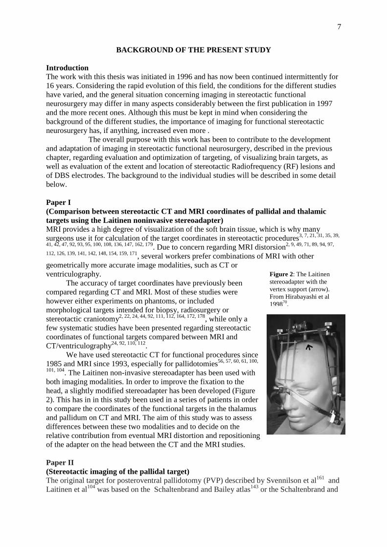
101, 104. The Laitinen non-invasive stereoadapter has been used with both imaging modalities. In order to improve the fixation to the head, a slightly modified stereoadapter has been developed (Figure 2). This has in in this study been used in a series of patients in order to compare the coordinates of the functional targets in the thalamus and pallidum on CT and MRI. The aim of this study was to assess differences between these two modalities and to decide on the relative contribution from eventual MRI distortion and repositioning of the adapter on the head between the CT and the MRI studies. Paper II (Stereotactic imaging of the pallidal target) The original target for posteroventral pallidotomy (PVP) described by Svennilson et al161 and Laitinen et al104 was based on the Schaltenbrand and Bailey atlas143 or the Schaltenbrand and
Figure 2: The Laitinen stereoadapter with the vertex support (arrow). From Hirabayashi et al 199870.

8
Wahren atlas144. The target was identified in relation to the 3rd ventricle, and located 20-22 mm lateral of the inter-commissural line (ICL), 2-3 mm in front of the mid-commissural point (MCP), 3-6 mm below the plane of the anterior and posterior commissures (AC-PC). The landmarks of the 3rd ventricle were originally chosen since they could be visualized on ventriculography. However, even when CT, and later MRI, became available for stereotactic procedures, many still continued to rely on ventriculography for the targeting procedure97, 115,
120, 146, 149. Several of those who abandoned ventriculographies in favor of MRI did however still proceed by first identifying the landmarks of the 3rd ventricle on MRI, and defined the pallidal target in relation to these landmarks4, 33, 35, 42, 50, 90, 176.
However, if one uses judicious scanning sequences, MRI will visualize more of the brain than just the landmarks of the 3rd ventricle, and if one can visualize the internal capsule, the globus pallidus internus (GPi), the lamina medullaris interna, the globus pallidus externus (GPe), the lamina medullaris externa, the putamen, and the optic tract, within reasonable time and with minimal distortion of the frame fiducials, then atlas-based coordinates are of limited value and may become redundant. With direct visualization of the individual pallidal targets, each patient will be his or her own atlas. In the present study we evaluated direct stereotactic visualization of the pallidal target and its surrounding. Paper III (A quick and universal method for stereotactic visualization of the subthalamic nucleus before and after implantation of deep brain stimulation electrodes) T2-weighted MRI sequences were first presented by Benabid et al12 as an option for direct visual identification of the subthalamic nucleus. Despite this, the Grenoble group still uses ventriculography in the surgical targeting of the STN. This is in accordance with the general situation, where many groups continued for a long time to determine the position in relation to landmarks of the 3rd ventricle, identified on T1-weighted sequences, instead of performing a direct visualization of the nucleus itself.
One reason for this might be that the early publications regarding direct visualization of the STN all used volumetric T2- weighted sequences with a long acquisition time10, 128, 145,
180, sometimes with an additional need of reformatting the images and/or additional T1-weighted sequences10, 155. Such long acquisition will often result in the need of general anesthesia. When analyzing the literature regarding postoperative imaging it was clear that the quality of these images, with a few exceptions145, 155, was not of such a quality that the electrode contacts could be localized in the target structure10, 81, 140.
In the present paper we present the experience from a number of centers regarding the use of a T2-weighted, fast-acquisition non-volumetric MRI protocol145 for direct targeting of the STN, as well as for postoperative verification of the electrode location.
Paper IV ("Sukeroku sign" and "dent internal-capsule sign"--identification guide for targeting the subthalamic nucleus for placement of deep brain stimulation electrodes) The target in the STN can be identified by a direct or indirect method, or a combination of both. The direct method consists of a direct visual identification of the target point in the STN on MRI, while with the indirect method the location of the target point is decided from a stereotactic atlas, based on its relation to landmarks of the 3rd ventricle.
When using direct targeting, a good anatomical knowledge concerning the area of interest is vital. Sometimes the lateral and inferior borders of the STN may be difficult to distinguish from the substantia nigra (SN). The use the Sukeroku sign and the dent internal-capsule-sign may aid in that respect. The purpose of the present study was to present these signs and to assess their usefulness in targeting of the STN.
9
Papers V & VI (Is there a relationship between size and site of the stereotactic lesion and symptomatic results of pallidotomy and thalamotomy? & Impact of parameters of radiofrequency coagulation on volume of stereotactic lesion in pallidotomy and thalamotomy) Lesional procedures have demonstrated substantial symptomatic improvements in both PD and essential tremor (ET) patients 5, 6, 16, 17, 23, 104, 129. The procedures of choice have been ventrolateral/Vim thalamotomies for non-parkinsonian tremor, as well as for tremor dominant PD48, 82, while posteroventral pallidtomy has been preferred for patients with advanced PD9, 35, 36, 100, 103, 109. The symptomatic profile of pallidotomy seems to vary according to the different symptoms: an excellent effect has been reported regarding dyskinesias, while the effect on tremor, akinesia and dystonic painful cramps is more varying9, 83, 109, 132, 163. Even though both procedures are well established there has been some lack of consensus regarding the optimal location of the lesion within the target area, as well as regarding the optimal volume of the lesion. The volume of the lesion constitutes one of the most important issues regarding lesional procedure, since not only is it unclear how the effect of the lesion is correlated to the volume, but we are currently unable to predict the size of the lesion, in order to encompass the target area, without encroaching on adjacent structures.
The aim of the present studies was to analyze if the location and size of the lesions in the Pallidum and VL-thalamus might influence the effect on the various symptoms, and further to evaluate the respective role of the various RF parameters (temperature of coagulation, time of application of RF current) in determining the size of the lesions.
10
AIMS The specific aims of this thesis were:
• To assess differences between CT and MRI regarding coordinates of the functional targets in the thalamus and pallidum, and to evaluate the composite contribution from MRI distortion and repositioning of the Laitinen non-invasive Stereoadapter towards these differences.
• To evaluate on proton density MRI sequences direct stereotactic visualization of the pallidal target and its surroundings.
• To evaluate in different centers, different countries, and on different MR machines, a T2-weighted, fast-acquisition non-volumetric MRI protocol for direct targeting of the STN, as well as for postoperative verification of electrode locations.
• To define the Sukeroku sign and the dent internal-capsule-sign and to assess their usefulness in targeting of the STN.
• To analyze the influence of location and size of pallidotomies and thalamotomies on effects and side effects.
• To analyze the impact of the various RF parameters in determining the size of stereotactic lesions.
11
MATERIALS AND METHODS
Paper I A preoperative stereotactic CT and a preoperative stereotactic MRI were performed in 34 patients (19 males, mean age 65 years (range 44-79)). Thirty patients had PD and four ET. The target was in 28 cases the PVP (16 left) and in 6 the ventrolateral (VL) thalamus (5 left).
The CT studies were performed on a Philips CT scanner (Philips Tomoscan LX, The Netherlands). The scanning procedure has been previously described55, 60, 61. In short, the scans were performed parallel to the transverse bars of the Stereoadapter, with 1.5-mm-thick contiguous slices in 2-mm-steps, from above the foramina of Monro until the second transverse bars and cerebral peduncle were reached. After the CT scanning, the Stereoadapter was detached and later remounted for the MRI Study.
The MRI studies were performed on a 0.5-tesla superconducting MR scanner (Philips Gyroscan T 5 II). The Stereoadapter was remounted on the patient’s head using the same positions as for the previous CT. Thirty 2-mm-thick contiguous slices were obtained with an axial, T1-weighted, 3-D fast field echo volume sequence parallel to the transverse bars of the adapter (flip angle 30; TR 30 ms; TE 13 ms; number of excitations 2; in-plane resolution 0.78 x 0.78 mm (field of view 200 and matrix 256 x 256); phase encoding left to right).
Enlarged hard copies of CT and MRI films were obtained from the level of the foramina of Monro down to the middle of the aqueduct, including the second pair of the transverse bars of the stereoadapter. The identification of landmarks, target, and coordinates were performed on both the CT and the MRI images. The AC was localized on a slice 4 mm ventral to the ventralmost margin of the foramen of Monro101. The PC was identified on the slice lying just above the slice with the beginning of the aqueduct. The distance between AC and PC was measured, giving the length of the ICL.
The target point was based on the atlas of Schaltenbrand and Wahren144. After the anatomical target point had been decided, its coordinates were calculated in relation to the stereoadapter.
The x, y, and z coordinates obtained from the MRI study were compared with those obtained from the CT study (Figure 3). The vectorial distance between the MRI- and CT-defined targets was calculated using the equation:
√(Xmr – Xct)2 + (Ymr – Yct)2 + (Zmr – Zct)2
where Xct, Yct and Zct represent the coordinates on CT, and Xmr, Ymr and Zmr represent the coordinates on MRI. The lengths of the ICL was further compared between the two modalities.
The differences in each coordinate location were measured by subtracting the CT coordinate value from the MRI coordinate value. The difference in target position was indicated as negative if the MRI target was medial, posterior, or ventral to the CT target, and positive if lateral, anterior or dorsal.

12
Paper II Forty-eight consecutive patients (32 males) scheduled for pallidal surgery were included in the present study. The mean age was 60 years (range 43–76) and duration of disease 12.6 years (range 3–30).
Imaging was performed with a 1.0 Tesla superconductive scanner (Magnetom Impact Expert, Siemens, Erlangen, Germany). A T1-weighted spin-echo sequence was obtained (TR/TE 180/15; field of view, 25 cm; slice thickness, 5 mm; matrix, 192 × 256; excitations, 2; imaging time, 1 minute 12 seconds). Three slices without gap were obtained from the midline for visualization of the AC-PC plane, and 3 slices for identification of the transverse bars of the Laitinen stereoadapter57. This was followed by a transverse Turbo spin- echo proton density sequence angulated parallel to the transverse bars (TR/TE 4000/15; echo-train, 7; field of view, 25 cm; slice thickness, 2 mm, gap, 0; matrix, 210 × 256; excitations, 3; imaging time, 6 minutes and 5 seconds). The target area was covered by 34 slices and reconstructions for measurements performed according to the plane of the transverse bars. A coronal sequence perpendicular to the former and centered on the mammillary bodies was further obtained using the same scanning parameters. In some cases this was replaced by a coronal Turbo true inversion recovery sequence (TR/TE 5600/60 TI350; echo-train, 11; field of view, 25 cm; slice thickness, 5 mm; gap, 0; matrix, 198 × 256; excitations, 2; imaging time, 3 minutes 27 seconds).
Axial and coronal scans covering the target area and relevant landmarks were enlarged 1.4 times and printed on hard copies of film. The target was indicated in the axial plane in the posterior-ventral area of the Gpi, from the AC-PC plane and ventrally. The depth of the target was assessed in relation to the optic tract, the ambient cistern and the supra-amygdala on the coronal scans. The coordinates on the most ventral point of the target was thereafter calculated in relation to the Laitinen stereoadapter. The following measurements were further performed as a part of the study: laterality in relation to midline of: the pallidocapsular border, the lamina medullaris interna, the medial border of the putamen. Also the width of the posteroventral pallidum (PVP) at target level was measured. The measurements were performed, 2 mm anterior of the MCP and 2 - 4 mm below the AC–PC plane. The width of the PVP was measured on the same slice. Paper III This was a multicenter study involving eight centers in six countries. The investigations were performed using 1.5 tesla MRI scanners (Siemens, Philips and General Electric) in 7 centers, and a 1.0-tesla machine in one center. The Laitinen, Leksell and Cosman Roberts Wells (CRW) stereotactic frames were used.
Figure 3; Stereotactic CT and stereotactic MRI of the same patient. The scans are at the level of the pallidal target. The inter-aural (horizontal) line represents the reference for the anteroposterior coordinate of the target. The line vertical projecting from the frontal pin onto the inter-aural line represents the reference for the lateral coordinate of the target. The target in the left posteroventral pallidum is indicated by a dot. From Hirabayashi et al 199870.

13
More than 85 patients implanted with DBS electrodes in the STN were included in the present study. These patients were investigated using transaxial and coronal scans, with the parameters presented in table 1. Postoperative MRI, with or without the stereotactic frame was further performed in some of the patients, using the same parameters.
Table 165. Some of the parameters of MRI (axial scanning) used.
London Trondheim Enschede Nara Cape Town Stockholm Umeå/Uppsala
Frame Leksell Leksell no frame CRW Laitinen Laitinen Laitinen/Leksell Scanner GE Siemens Philips Siemens Siemens Siemens Philips TR 3,500 3,000 3,000 4,000 3,000 6,200 3,000 TE 90.9 82 85 17 96 112 84 Thickness of
slice/gap, mm 2/0.2 2/0 2/0 2/0 2/0 2/0 2/1 Excitations, n 4 3 3 3 3 5 4 Field of view, mm 250 x 250 250 x 250 220 x 220 256 x 256 230 x 230 250 x 220 230 x 250 Slices, n 22 19 variable variable 15 17 22 Acquisition time 7 min 7 s 7 min 48 s 6 min 42 s 5 min 30 s 5 min 37 s 7 min 20 s 3 min 5 s
TR = Time of repetition; TE = time of echo; CRW = Cosman Roberts Wells; GE = General Electric.
Paper IV This study was based on pre-operative MRI images from five patients (3 males) aged 31 -76 years, operated with STN DBS for PD. DBS electrodes had been successfully implanted in the STN in these patients, resulting in a mean improvement of the Unified Parkinson Disease Rating Scale (UPDRS)40 from 35.6±4.3 before surgery, to 14.6±2.9 after surgery. All patients had an improvement of more than 43% (mean, 58%).
Axial and coronal short Tau inversion recovery (STIR) images were acquired [2D-fast SE: repetition time (TR) =5,000 ms, inversion time (TI) = 150 ms, echo time (TE) = 10 ms, echo train length (ETL) = 8, field of view (FoV) = 256 mm, slice thickness = 3 mm, slice spacing = 2 mm, interleave acquisition, matrix = 256 × 256, averaging = 2] using a 1.5-T scanner. The STIR sequence generates clear contrast between high signal from gray matter and low signal from white matter, and both the SN and the STN appear with high signal. The axial slices were parallel to the AC–PC line and the coronal perpendicular to this line.
The target was initially placed 12 mm lateral of the ICL, 2 mm behind the MCP and 4 mm below the AC-PC-plane, and was adjusted according to the location and shape of the STN as seen on the MRI. Single or multitrack MER was performed during surgery, and used for determination of the electrode depth. After this the microelectrode was replaced with the DBS electrode in the center of the STN. Within a week after the implantation an MRI identical to the pre-operative investigation was aquired for determination of the electrode location. The coordinates of the target were determined from the postoperative MRI and used as reference for the subsequent study.
In order to determine to the accuracy of STN localizing, five board-certified radiologists served as readers. None of them had any previous experience of STN localization procedures or any knowledge of the Sukeroku sign or the dent internal-capsule sign (Figure 4).
The readers were provided with an anatomical atlas of the brain51 and asked to identify the center of the STN on the pre-operative MRI images of each of the five patients, based on the information available within the atlas. The time needed to identify the target in the coronal, as well as in the axial planes, was recorded together with the coordinates of the selected point.

14
After a minimum of one month the experiment was repeated, but this time the readers were provided with an instruction sheet containing detailed information on the Sukeroku sign and dent internal-capsule sign, before performing the task.
The deviation of the targets selected by the readers was then analyzed in relation to the actual target, that is, the final position of the electrode decided from the post-operative MRI.
Papers V & VI Forty-six consecutive patients who had undergone a total of fifty functional stereotactic lesions (29 unilateral and 1 staged bilateral PVP, 2 ipsilateral re-pallidotomies, 13 unilateral and 1 bilateral thalamotomy, and 1 ipsilateral combined staged PVP and thalamotomy) were retrospectively analyzed. Forty-five patients had PD and one ET. The mean age of the patients was 64.8 ± 8.3 years and 35 were males. The surgical procedure is presented in detail below. A postoperative stereotactic CT (Siemens, Erlangen, Germany)/MRI scanning (1.5 Tesla, Philips, The Netherland) was performed after a mean of 6 months (range 3 – 24) after the procedure, using the Laitinen non-invasive stereoadapter 101. This allowed a scanning plane identical to the preoperative scanning plane, regarding orientation and slice thickness (2mm). Enlarged film copies were used to evaluate the stereotactic lesion and calculate its volume. The lateral (x) and anteroposterior (y) diameters of the lesion were measured at the level of the maximal diameter of the lesion, and the dorsoventral (z) diameter was calculated by identifying the number of 2 mm-thick scans on which the lesion could be visualized. The volume of the lesion was calculated using the spheroid volume formula, Volume = 4/3 * π * (x /2) * (y/2) * (z/2). The AC, PC, and ICL were identified on the postoperative studies and the coordinates of the center of the lesion determined in relation to these landmarks and to the intended target. The
Figure 4: Instruction sheet used to explain the “Sukeroku sign” and the “dent internal-capsule sign”. a, d, e STIR images. a, b, c “Sukeroku sign” is used for identification of the STN on coronal slices. The STN (arrows, a) and SN (arrowheads, a) appear together on the coronal plane perpendicular to the AC–PC plane, at the level of the internal auditory canal, with the STN cranial and lateral to the SN (schematic drawing, b), resembling the cosmetically highlighted eye of a Japanese traditional literary hero, Sukeroku (c). d, e “Dent internal-capsule sign” is used for identification of the STN on axial slices. On the axial plane parallel to the AC–PC line at the level of the mamillary bodies, the STN (oval area, d) appears to stick into the internal capsule, creating a dent on the margin of the internal capsule´(dotted line, d), while the margin of the internal capsule appears straight on the adjacent caudal plane at the level of the SN (dotted line, e). From Taoka et al 2009167.

15
coordinates of the edges of the lesion were further identified in the three planes in order to decide the extension of the lesion in relation to the intended target point. The location/extension of the lesions were then analyzed with regard to the clinical effect.
The clinical effect was decided during a qualitative clinical assessment of akinesia, tremor, dyskinesia and dystonia. The effects were rated in three steps: excellent (symptoms practically eradicated); good/fair (~ 50 % symptom reduction); and no change (no substantial effect or absence of effect). Side effects were further documented.
Furthermore, The volume of the lesions were correlated to the parameters of the Radiofrequency coagulation (temperature, duration of heating) in order to evaluate whether the lesion volume could be predictable

16
SURGICAL TECHNIQUE
All procedure in papers I-II & V-VI were performed in local anaesthesia using the Laitinen strereotactic system 57. The Stereoadapter has been previously presented in detail57, 60, 62, 101. It is a noninvasive springy frame made of aluminum alloy, which is mounted on the head using ear plugs and a nasion support. The lateral triangular components, contain four transverse bars of 2-mm thickness and separated by 25 mm. These components are pressed against the scalp with the aid of a connector plate over the vertex. The modification of the adapter in paper I (Figure 1) consisted of a vertex support hooked between the calvarium and the center of the connector plate. On the axial scans, the reference structures of the adapter are: for the x= laterality coordinate: a perpendicular between the frontal pin and the line between the anterior margins of the posterior ear arms of the triangular components. For the y = A-P coordinate: the line between the anterior margins of the posterior ear arms of the lateral triangular components (= inter-aural line). And for the Z = dorso-ventral vertical coordinate, the level of the scans showing the nearest pair of transverse bars. The same references were used for the axial MRI scan, although here, for MRI studies, since the adapter as such is not visible on MRI, plastic tubes filled with olive oil were attached to the reference structures to allow their visualization.
Identification and calculation of target coordinates was performed manually on enlarged hard copies of CT / MRI films using a ruler, a minicalculator and a thin pen or needle 68. The standard thalamic target was located 6-7 mm anterior to the PC, 13-15 mm lateral of the midline of the 3rd ventricle, at the level of the ICL. The pallidal target was identified 2 mm anterior to the MCP, 2 – 3 mm lateral of the internal capsule, and 2 mm above the optic tract, and adjusted according to visualisation of the individual target structure.
The patient was placed in a semi-lying position on the operation table, in order to minimize leakage of cerebrospinal fluid (CSF). After partial shaving a linear incision of approximately four centimetres was placed centred over the place for the burr-hole. A burr-hole of 8 mm in diameter was made using a hand-drill, and placed just anterior to, or at, the coronal suture and approximately 2.5 – 4 cm lateral of the midline, depending on the target. Durotomy and corticotomy were performed with monopolar coagulation.
In all procedures, the same RF generator (512-KHz RF generator, IBBAB, Gothenburg, Sweden) and the same RF electrode (custom made Laitinen-Wicksell monopolar thermocouple electrode, IBBAB, Gothenburg, Sweden) were used. The electrode had a non-insulated tip 2 mm long and 1.8 mm in diameter. The RF generator and electrode were used for dynamic impedance monitoring, stimulation and coagulation.
Macrostimulation with 6Hz up to 10mA, and with 60 or 120 Hz up to 5 mA was performed at various points at target level to evaluate effect and side-effects. The effect of intraoperative stimulation on symptoms such as tremor, rigidity, hypokinesia, and eventual induction of dyskinesias was evaluated and possible side effects, such as visual phenomena, capsular response, speech alterations and paresthesias were sought. In all patients in whom the Laitinen system was used, surgery was performed without microelectrode recording.
The pallidal lesions were performed with 75-85º C during 60 s, at 3-4 levels, starting 6 mm above the most ventral target point, with one lesion every 2 mm, provided that macrostimulation did not yield capsular or visual responses. The thalamic lesions were performed with 70 - 75º C during 30 - 60 s at 1-3 levels separated by two mm. The number of lesions at each target point was dictated by the size of the target area (the pallidal target being larger than the thalamic one) and of course by the clinical response.
In patients who underwent DBS (Papers III and IV), the surgical technique and frames used varied slightly among centers. The stereotactic frames used were the Leksell, the Laitinen or the Cosman Roberts Wells (CRW). Macrostimulation was used in all centers to

17
evaluate the effects and side effects, prior to implanting the DBS electrode. Occasionally microrecording was performed in one of the centers (Nara medical University), initially using a home-made system (Paper III), and subsequently using the Leadpoint system (Paper IV). Single or multitrack microelectrode recordings (maximum three tracks) were obtained and the depth of the DBS electrode was determined based on the best electrical activity of the STN recordings.
STATISTICS
The values are reported as mean ± SD (standard deviation), and range, if not otherwise indicated. A p-value of ≤ 0.05 was considered statistically significant. Paper I Two-sample paired t-test was used for analysis of the differences between CT and MRI measurements. Two sample unpaired t-test was done in order assess the coordinate differences according to the target (PVP & VL-thalamus; left & rigth) and whether or not the vertex support of the adapter had been used. Paper II Wilcoxon’s signed rank test or Student’s t-test for paired samples were used. Paper V & VI Paired two-tailed Student’s t-test was applied for analysis of statistical significant differences between the means regarding lesion volume on CT and MRI.
The relationship of coagulation temperature, length of coagulation and duration of coagulation to lesion volume, and lesion volume to clinical outcome, was analyzed using ANOVA, and logistic regression analysis was used for evaluation of predicting factors.

18
RESULTS
Paper I The distribution of the MRI coordinates in relation to the CT coordinates in the transverse plane is demonstrated in figure 5.
The differences regarding the x coordinates on CT and MRI ranged from –1.75 to 2.5 mm (mean 0.27±0.95, p = ns., 95 % confidence interval range –0.057 to +0.604). The difference was < 1 mm in 26 of the patients. The corresponding figures regarding the y coordinates were -3.75 - 3.75 mm (mean 0.76±1.11, p < 0.001, 95% confidence interval range 0.403 - 1.176). The corresponding figures regarding the z coordinates were –2.5 - 3.0 mm, (mean 0.76±1.4, p < 0.01, 95% confidence interval range 0.276 - 1.253). The distribution in the coronal plane of the MRI coordinates in relation to the CT coordinates is presented in Figure 6.
The vectorial difference between the coordinates of the same target on CT and MRI ranged from 0.61 to 3.76 mm (mean 2.13±0.95, 95% confidence interval range 1.824 - 2.427).
Figure 5: Distribution of MRI coordinates in the transverse plane in patients with (black dots) and without (empty dots) vertex support. The horizontal (x) axis represents the coordinate difference in the medial to lateral direction. A positive value means that the MRI coordinate is laterally deviated, and a negative value that it is medially deviated, in relation to the CT coordinate. The perpendicular (y) axis represents the coordinate difference in the anteroposterior direction. A positive value means that the MRI coordinate is anteriorly deviated and a negative value that it is posteriorly deviated in relation to the CT coordinate. From Hirabayashi et al 199870.
Figure 6: The distribution of the MRI vs. CT coordinates in the coronal plane in patients with (black dots) and without (empty dots)vertex support on the Stereoadapter. The horizontal (x) axis represents the coordinate difference in the medial to lateral direction. The perpendicular (z) axis represents the coordinate difference in the dorsocaudal direction. A positive value means that the MRI coordinate is dorsally deviated and a negative value that it is ventrally deviated in relation to the CT coordinate. From Hirabayashi et al 199870.
19
The length of the AC-PC line was on CT in mean 24.82±1.65 mm (range 21.5 - 27.5) and on MRI 24.46±1.62 mm (range 19.5 - 27.0). The difference in length was in mean –0.37±0.9 mm (range –2 - 2.25, p < 0.05).
The differences regarding the pallidal target between CT and MRI were in mean 0.12±0.88 mm in x, 0.80±1.15 mm in y, and 0.98±1.79 mm in z. The corresponding figure concerning the thalamic target were 1.01±0.99 mm in x, 0.79±0.99 mm in y, and 1.13±1.22 mm in z. The differences were not statistically significant.
The corresponding figures concerning the left-sided targets were 0.48±1.00 mm in x, 1.13±0.92 mm in y, and 0.87±1.43 mm in z. Concerning the right-sided targets –0.06±0.77 mm in x, 0.24±1.19 mm in y, and 0.60±1.39 mm in z. The differences regarding the two sides was only significant regarding the y coordinate (p<0.05).
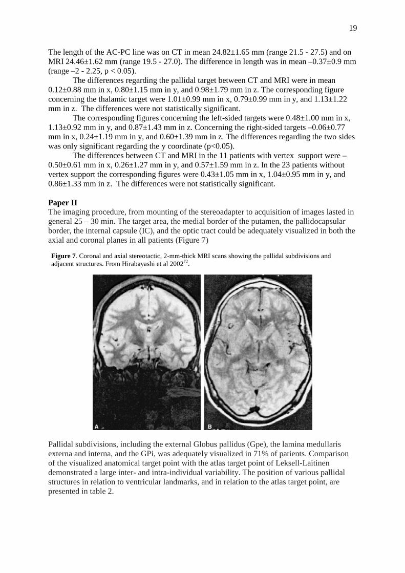
The differences between CT and MRI in the 11 patients with vertex support were –0.50±0.61 mm in x, 0.26±1.27 mm in y, and 0.57±1.59 mm in z. In the 23 patients without vertex support the corresponding figures were 0.43±1.05 mm in x, 1.04±0.95 mm in y, and 0.86±1.33 mm in z. The differences were not statistically significant. Paper II The imaging procedure, from mounting of the stereoadapter to acquisition of images lasted in general 25 – 30 min. The target area, the medial border of the putamen, the pallidocapsular border, the internal capsule (IC), and the optic tract could be adequately visualized in both the axial and coronal planes in all patients (Figure 7)
Pallidal subdivisions, including the external Globus pallidus (Gpe), the lamina medullaris externa and interna, and the GPi, was adequately visualized in 71% of patients. Comparison of the visualized anatomical target point with the atlas target point of Leksell-Laitinen demonstrated a large inter- and intra-individual variability. The position of various pallidal structures in relation to ventricular landmarks, and in relation to the atlas target point, are presented in table 2.
Figure 7. Coronal and axial stereotactic, 2-mm-thick MRI scans showing the pallidal subdivisions and adjacent structures. From Hirabayashi et al 200272.

20
Paper III The STN could in most cases be adequately visualized on both the axial and coronal scans. The STN could normally be further demarcated in relation to its surroundings when manipulating the contrast enhancement on the screen after the scanning. This was considered especially usefull for discriminating between the STN and the substantia nigra on the axial scans of the ventral part of the target area. The STN and its surrounding structures are demonstrated on axial and coronal scans in Figure 8. The location of bilateral DBS electrodes in the STN on an axial scan is presented in Figure 9, and the location of a unilateral STN DBS electrode on coronal and axial scans is shown in Figure 10.
Figure 8: STN and surrounding structures shown on a 2-mm-thick axial and 3-mm- thick coronal scan (acquisition time for each sequence 7 min 48 s, Siemens machine). From Hariz et al 200365.
Table 272.

21
The scanning parameters used in the various centers are described in some detail in table 1. Acquisition time for each scan varied from 3 min 5 s to 7 min 48 s between the different centers.
Figure 9: Bilateral DBS electrodes in the STN shown on a 2-mm-thick axial scan (acquisition time 7 min 7 s, GE machine). From Hariz et al 200365
Figure 10: A 3-mm-thick coronal and a 2-mm-thick axial scan showing a unilateral left-sided DBS electrode (acquisition time 4 min 3 s, Philips machine). From Hariz et al 200365
22
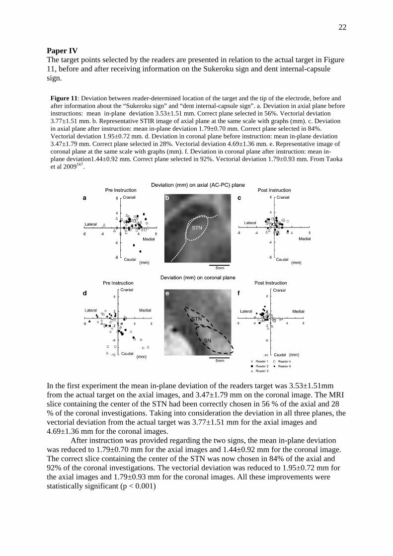
Paper IV The target points selected by the readers are presented in relation to the actual target in Figure 11, before and after receiving information on the Sukeroku sign and dent internal-capsule sign.
In the first experiment the mean in-plane deviation of the readers target was 3.53±1.51mm from the actual target on the axial images, and 3.47±1.79 mm on the coronal image. The MRI slice containing the center of the STN had been correctly chosen in 56 % of the axial and 28 % of the coronal investigations. Taking into consideration the deviation in all three planes, the vectorial deviation from the actual target was 3.77±1.51 mm for the axial images and 4.69±1.36 mm for the coronal images.
After instruction was provided regarding the two signs, the mean in-plane deviation was reduced to 1.79±0.70 mm for the axial images and 1.44±0.92 mm for the coronal image. The correct slice containing the center of the STN was now chosen in 84% of the axial and 92% of the coronal investigations. The vectorial deviation was reduced to 1.95±0.72 mm for the axial images and 1.79±0.93 mm for the coronal images. All these improvements were statistically significant (p < 0.001)
Figure 11: Deviation between reader-determined location of the target and the tip of the electrode, before and after information about the “Sukeroku sign” and “dent internal-capsule sign”. a. Deviation in axial plane before instructions: mean in-plane deviation 3.53±1.51 mm. Correct plane selected in 56%. Vectorial deviation 3.77±1.51 mm. b. Representative STIR image of axial plane at the same scale with graphs (mm). c. Deviation in axial plane after instruction: mean in-plane deviation 1.79±0.70 mm. Correct plane selected in 84%. Vectorial deviation 1.95±0.72 mm. d. Deviation in coronal plane before instruction: mean in-plane deviation 3.47±1.79 mm. Correct plane selected in 28%. Vectorial deviation 4.69±1.36 mm. e. Representative image of coronal plane at the same scale with graphs (mm). f. Deviation in coronal plane after instruction: mean in-plane deviation1.44±0.92 mm. Correct plane selected in 92%. Vectorial deviation 1.79±0.93 mm. From Taoka et al 2009167.

23
The time for localization of the target in the axial and coronal plane was reduced from in mean 15.6±4.03 min to 9.4±1.94 min (p < 0.05), after instructions regarding the sign was provided. Paper V & VI The distribution of coagulation parameters according to temperature, rostro-caudal length of coagulated area, and total duration of coagulation is presented in table 3. Table 3. Distribution of coagulation parameters according to temperature, rostro-caudal length of coagulated area, and total duration of coagulation. From Hirabayashi et al 201269.
Number of lesions Temperature (ºC) 70-73 3 74-77 17 78-81 12 82-85 18 Duration (s) 90-160 10 160-230 23 230 – 300 17 Length (mm) 2.5 – < 5.5 14 5.5 – < 8 16 8 – 10.5 20
Lesion volume versus temperature, duration of coagulation, and length of coagulation area The mean lesion volume in the whole material was 75.9 ± 56.6 mm3 (range 4.2 - 254.9) and the temperature 79.1 ± 4.3 ˚C (range 70 – 85). As seen in Figure 12 the higher the temperature, the larger the volume, for a given length of coagulated area (correlation coefficient 0.516, p < 0.001). Furthermore, the shorter the length of the coagulation, the stronger was the correlation between volume of lesion and temperature of coagulation. A logistic regression analysis is presented in Figure 13 , where the relation between volume and temperature is described by the equation: log Vol. = -1.62 + 0.04 * T. (Correlation coefficient 0.469, p<0.001).

24
Figure 12. Scatter diagram of lesion volume versus temperature of coagulation. The patients were divided into three groups according to rostro-caudal length of coagulation. From Hirabayashi et al 201269.
Figure 13. Scatter diagram of logarithm of lesion volume and temperature of coagulation. The patients were divided into three groups according to rostro-caudal length of coagulation From Hirabayashi et al 201269.
The dorso-ventral length of the coagulation was in mean 6.5 ± 2.0 mm (range 2.5 – 10). The relation between volume and length of coagulation is demonstrated in Figure 14. The longer the coagulation area, the larger was the volume of the lesion (correlation coefficient 0.346, p < 0.05).

25
Figure 14. Scatter diagram of lesion volume versus the length of rostro-caudal coagulation. The patients were divided into 4 groups according to the temperature of coagulation. From Hirabayashi et al 201269.
The mean duration of coagulation was 201 ± 54 s (range 90 - 300). The relation between duration of coagulation and lesion volume is shown in Figure 15. The longer duration of coagulation, the larger volume of lesion (correlation coefficient 0.356, p < 0.05). Figure 15. Scatter diagram of lesion volume versus total duration of coagulation. The patients were divided into 4 groups according to the temperature of coagulation. From Hirabayashi et al 201269.
A multiple regression analysis of the relationship between lesion volume, temperature, length of coagulated area, and duration of coagulation, demonstrated the temperature to be the most important factor affecting the lesion volume (p<0.05).

26
Volume of Lesions on CT vs. MRI The relationship between lesion volume on CT and MRI in 18 pallidotomies and 2 thalamotomies analyzed with both methods is presented in Figure 16. In these patients, the mean lesion volume on CT scan was 74.5 ± 47.1 mm3 (range 4.2 - 177.0), and on MRI scan 80.6 ± 63.9 mm3 (range 6.1 - 218.2). There were no significant differences, but a strong correlation between CT and MRI volumes (correlation coefficient: 0.914, p< 0.0001). Lesion volumes and diameters for the whole material is presented in table 4. The coordinates of the center of the lesions in relation to the intended target point are presented in table 5. The center of the lesions was located significantly more anterio-dorsal in the pallidotomies and anterior in the thalamotomies than the target point. Figure 16. Relationship between lesion volumes on CT and MRI in 20 lesions analyzed with both methods. From Hariz et al 199764.
Table 464. Lesion volumes (mm3), diameters (mm), and statistics (Student's t test)
Volumes
Pallidotomies Thalamotom ies Statistics
mean±SD 87.08±58.44 46.95±40.09 p<0.05 95%CI 67.3- 106.9 23.8-70.1 range 9.63-254.84 4.1 8-135.04
Transverse diameter mean±SD 4.14± 1.36 4.17± 1.62 p= n.s. range 1.75-7.8 1.6-6.4 Anteroposterior diameter mean ±SD 4.99 ± 1.63 5.18±2.05 p= n.s. range 2-10.4 2-10.4 Dorsoventral diameter mean±SD
range 7.27±2.18
2-12 3.5± 1.22
2 - 6 p<0.0001
SD = Standard deviation; 95% CI = 95 % confidence interval

27
Table 564. Differences between coordinates of center of lesion and intended target point in 36 pallidotomies and 14 thalamotomies. Figures are presented for all three dimensions (X, Y, Z) as well as for the vectorial deviation (3D). Negative values indicates deviations in the medial, posterior and ventral direction regarding X, Y and Z, respectively. Pallidotomies Thalamotomies X mean ± SD 0.10±1.14 0.29±1.67 Range -2.0 – 2.9 -2.2 – 3.4 t-test p = n.s. p =n.s. Y mean ± SD 2.08±1.38 1.49±1.51 Range -1.0 – 5.0 0.0 – 4.8 t-test p < 0.0001 p < 0.01 Y mean ± SD 1.75±1.66 -0.35±1.15 Range -2.0 – 4.0 -2.0 – 2.0 t-test p < 0.0001 p =n.s. 3D mean ± SD 3.39±1.21 2.6±1.31 Range 0.0 – 5.88 0.0 – 5.0 t-test p < 0.0001 p < 0.0001 Macrostimulation, immediate postoperative effects and side-effects Following intraoperative macrostimulation, the target was shifted in an anterior and/or medial direction in 5 thalamic procedures due to paresthesias or capsular response. The latter side effect did also cause a change in an anterior and/or lateral direction in 3 pallidal procedures. The electrode was further retracted 2 – 3 mm in 13 patients due to optic response.
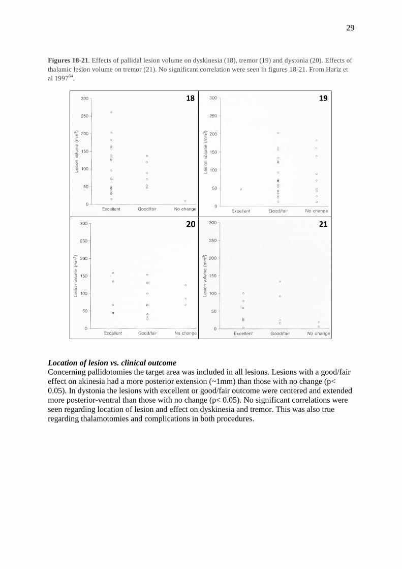
In the immediate postoperative period 85.7 % of the thalamotomies and 86 % of the pallidotomies were considered as successful. Of the patients with pallidotomies 7 (19 %) complications of longer duration were identified: 2 worsening of memory; 2 worsening of dysarthria; 2 leg weakness; 1 facial weakness. Of the patients with thalamotomies 6 (42 %) had complications of longer duration: 4 disequilibrium; 1 dysarthria; 1 leg weakness. Lesion Volume v.s clinical outcome The relation between lesion volume and effect of surgery is presented in table 5. All patients selected for pallidotomy suffered from moderate to severe akinesia. At a mean of 6 months after surgery 30.5 % of the pallidotomies resulted in a good/fair effect on akinesia and 69.5 % in no change. The lesion volume was larger in the group with a good/fair effect (p< 0.05) (Figure 17). Of the 32 patients with dyskinesia 78 % had an excellent effect, 19 % good/fair and 3 % no change. Of the 31 patients with tremor 6.5 % had an excellent effect, 64.5 % good/fair, and 29 % no change. Of the 16 patients with dystonia 31 % had an excellent effect, 50 % good/fair and 19 % no change. No significant correlation to lesion volume was seen regarding dyskinesia (Figure 18), tremor (Figure 19) or dystonia (Figure 20). Conceming the 14 patients with thalamotomy 57 % had an excellent effect on tremor, 28.5 % good/fair and 14.5 % no change. Except for akinesia, lesion volume was not correlated to outcome (Figure 21). In neither thalamotomies or pallidotomies were there any correlation between lesion volume and complications, and the result was not influenced by gender or side of surgery.

28
Table 664. Relation between lesion volume (mm3) and effect of surgery on the various symptoms, in pallidotomy and thalamotomy
Figure 17. Correlation between lesion volume and outcome regarding akinesa in pallidotomy (p < 0.05). From Hariz et al 199764.
29
Figures 18-21. Effects of pallidal lesion volume on dyskinesia (18), tremor (19) and dystonia (20). Effects of thalamic lesion volume on tremor (21). No significant correlation were seen in figures 18-21. From Hariz et al 199764.
Location of lesion vs. clinical outcome Concerning pallidotomies the target area was included in all lesions. Lesions with a good/fair effect on akinesia had a more posterior extension (~1mm) than those with no change (p< 0.05). In dystonia the lesions with excellent or good/fair outcome were centered and extended more posterior-ventral than those with no change (p< 0.05). No significant correlations were seen regarding location of lesion and effect on dyskinesia and tremor. This was also true regarding thalamotomies and complications in both procedures.

30
DISCUSSION
Paper I In this study of differences between target coordinates obtained from CT and MRI we
found significant differences regarding the anteroposterior y and dorsoventral z coordinates. We did further find a difference concerning the side of the target, where the left-sided targets showed a significant difference regarding the y coordinate. This latter finding might be due to inhomogeneities in the magnetic field causing geometric distortion in the frequency-encoding direction, which in our examinations was from left to right, or because there were more left-sided than right sided targets (21 left, 13 right targets).
The vectorial difference between CT and MRI was always in the rostrocaudal direction (mean 2.13 mm), where the MRI target seemed to lie more anterior and dorsal, that is, more rostral, than the CT target.
In this study the CT was the reference, against which the MRI scanning and MRI coordinates were assessed. The discrepancies of MRI coordinates in relation to CT coordinates will therefore probably be multifactorial and represent the sum of several potential errors, such as target selection in relation to ventricular landmarks (which are better visualized on MRI), repositioning errors of the stereoadapter, and MRI distortion.
The possible contribution by true MRI distortion is difficult to assess. Several MRI-inherent factors might have contributed. (a) Magnetic field inhomogeneities causing geometric distortion, as discussed above concerning differences between the right and left side. Such inhomogenities might also influence the definition of the AC and PC on the image, and hence, the antero-posterior position (y) of the target. (b) Field inhomogeneities and gradient nonlinearities resulting in potatoe-ship effect and warped shape of the selected slice might also add to the distortion. The effect of this should however be limited due to the closeness of the reference fiducials of the stereoadapter to the head. c) The impact of metal artifacts might be considered negligible since the adapter is made of MRI compatible materials. (d) Magnetic susceptibility artifacts52 can also be considered negligible, since the targets were central in the brain, far from any air-filled bony compartments, that is, far away from the air-tissue interface. (e) Most importantly, chemical shift as a source of distortion52,
116 may be of importance, since we used olive-oil-filled fiducials. In a study by Taha et al164 it was shown that the MR image of petroleum-filled fiducials shifted more anteriorly and inferiorly than fiducials with chromium chloride, resulting in a posterior and superior shift of the target coordinates. However, in our study, the shift of the MRI target was always anterior on MRI compared to CT. If that shift was due to a chemical shift affecting the position of the fiducials on MRI, then when the fiducials shifted anteriorly, the y coordinate of the target measured in relation to these fiducials should have ‘shifted’ posteriorly on the MRI compared to CT, i.e. the value of the y coordinate on MRI should have been less than the value on CT. This was however not the case.
The reason for which we had used olive oil was due to the fact that copper sulfate tends to disintegrate over time, which requires regular refilling of the tubes prior to each MRI session. This was found cumbersome and time consuming. However, no matter the case whether olive oil contributed or not to the distorsion, and in that case in which direction, in order to settle the issue, we no longer use olive oil to fill in the tubes of the reference fiducials, neither in the Laitinen MRI system nor in any other. CuSO4 is now the norm across the line.
In this study the discrepancies between CT and MRI target coordinates were less than what could be expected based on the published experience of others2, 24, 112, 172, especially when considering the re-mounting of the adapter. In fact, the discrepancies were not larger than those found when comparing CT and ventriculography61.

31
In conclusion, what appeared to be significant in this study was the 3-D vectorial shift of coordinates affecting the rostrocaudal coordinates (y and z) of the stereotactic target on MRI. However, since this coincides with the direction of the electrode trajectory it would be relatively easy to account for by careful intra-operative impedance monitoring and macrostimulation64, 83. MRI guided stereotaxis with the Laitinen system can obviate the need for CT to obtain target coordinates in functional stereotactic procedures. Paper II We presented in this study a fast technique based on proton density MRI for direct visualization of the pallidal target area under stereotactic conditions. The position of the target point displayed large inter- and intra-individual variations in the 96 analyzed hemispheres. This was demonstrated by the pallidocapsular border, whose laterality from the midline varied from 15.5 - 25.0 mm in different individuals. Further, when comparing the right and left hemispheres, the right pallidocapsular border was significantly more lateral than the left. This was also true regarding the lamina medullaris interna, hence demonstrating a more lateral position of the right Gpi. The width of the right PVP was further smaller than for the left PVP. Taking into consideration that the laterality of the medial border of the putamen did not differ between the hemispheres it can be deduced that the right PVP had a less medial extension than the left.
Inter and intra-individual variations regarding the basal ganglia and midbrain structures are well document in the literature, and this variability will increase with the distance to the landmarks of the 3rd ventricle53, 74, 87, 152. Of the different targets for stereotactic procedures in PD, such as the Zona incerta (Zi), Subthalamic nucleus (STN), and the Vim, the Gpi is the target located furthest from the landmarks of the 3rd ventricle. The wide variation of this target demonstrated in our material is therefore to be expected, and has been described earlier156. Taking this wide variation in consideration, it is obvious that targeting based solely on the landmarks of the 3rd ventricle will result in many targeting errors. This is also suggested by the large number of micro-electrode passes made during pallidal surgery by the groups relying on this technique4, 9, 35, 50, 90, 115, 169, 176. Since the passing of multiple electrodes might not be without certain risks25, 63, 182, an imaging technique allowing for a reduction of the number of passes might be of value.
Paper III Since access time to MRI scanners might be limited, and especially in order to avoid movement-artifacts created by the patients, without using general anesthesia, it is desirable to minimize scanning time, without compromising the quality of the images.
The results presented in this study, evaluating the visualization of the STN on various machines using T2 weighted sequences, represent a work in progress. The scanning parameters are being constantly refined in the different centers which partook in the study, and differences exist, especially concerning the acquisition time. It is worth noting, that even in the MRI center with the longest acquisition time, this time was still considerably shorter than the 20 – 25 min reported by most other groups10, 128, 145, 155, 180
The lack of homogenous scanning parameters between our groups reflects a well-known fact that settings and parameters cannot easily be translated from one MR scanner to another, not even when the scanners are of the same model or brand. There were further considerable interindividual differences concerning the visualization of the STN. These differences might be attributable to differences in iron content in the STN, or may perhaps be caused by differences in age and disease duration.

32
The visualization of electrode contacts and target structures after surgery was in many cases not optimal, especially on the coronal slices. The result on axial scans was however often satisfactory, as seen in Figures 2 and 3.
We have in this study demonstrated that direct visual targeting of the STN can be done on MRI scans of good image quality despite a short acquisition time. Whether the imaging technique presented here will decrease the number of (micro) electrode passes at surgery, and/or provides better results as compared with indirect targeting, remains to be analyzed. Paper IV The STN can be targeted in different ways. Indirect targeting is based on coordinates from stereotactic brain atlases in relation to landmarks of the 3rd ventricle. These coordinates are often adjusted with consideration to the ICL, in an attempt to improve the fit between the atlas and the individual patient. There are however inter-individual variations concerning the location, size and shape of the STN, and the STN tends further to change its size and shape with aging32. There are thus obvious advantages with direct visualization of the target with MRI10, 156. Further, in order to facilitate the process combinations of the two methods are widely used65, 135, 155, 181.
However, regardless of whether the direct targeting method is used alone, or in combination with indirect targeting, a clear visualization and recognition of the STN is essential for the targeting procedure. The STN is in most centers visualized using T2-weighted sequences65, 135, 155, 181. We have, however, in this paper tested the use of a STIR sequence generating a clear contrast between high signal from gray matter and low signal from white matter.
The STN is a small almond shaped structure located below the thalamus. Besides its limited size, there is little contrast between the STN and the surrounding structures, why visualization and recognition of the STN might be a problem, especially for those with limited experience. In the coronal plane and lower axial planes, there is further a risk of confusing the STN with the very adjacent SN, since the latter has a similar shape and signal intensity.
However, in the coronal plane perpendicular to the AC-PC plane, at the level of internal auditory canal, the STN is found adjacent to the SN, but located somewhat more cranially and laterally. The relation between the two structures can here be easily recognized, and the STN thus easily traced on the subsequent slices. When looking at these structures, it was noticed that there is a resemblance between them and the cosmetically highlighted eye of a Japanese traditional literary hero, Sukeroku, as seen in Figure 4c.
On the axial plane parallel to the AC-PC plane the dent internal-capsule sign can be helpful in locating the STN, and in differentiating it from the SN. In this plane, at the level of the mamillary bodies, the STN appears as if being stuck into the internal capsule. Thus, a dent is seen in the margin of the internal capsule, while this margin appears straight on the adjacent caudal plane at the level of the SN (Fig. 4).
In the current study we could demonstrate that the use of these signs were of significant help to a test group of radiologists without experience of STN localization. Both the accuracy and the speed of the targeting were significantly improved. We believe that these signs might prove useful to persons who are not familiar with the local anatomy, and perhaps also to experienced persons in cases where the STN cannot be easily distinguished on MRI.
A weakness with the current study was that the “true target” was based on the electrode position as seen on the postoperative MRI. The final placement of the electrode was however not decided solely based on anatomical targeting, but was adjusted in accordance with the findings from the MER. Thus, in some patients there may have been some discrepancy between the anatomical target as seen on MRI, and the final target. Another weakness is the limited number of patients evaluated.

33
Finally, this sukeroku sign has not been evaluated in other ethnicities than Japanese patients. This issue may be interesting to investigate further.
Paper V & VI Lesional procedures do indeed offer some advantages to DBS, such as a low cost, shorter and less complicated procedure, absence of hardware complications and battery replacements, and a less cumbersome follow-up. However, due to the irreversibility of lesions, the dangers inherent to simultaneous bilateral procedures, and the impossibility of postoperative “modulation” of the lesion, and in fact due also to aggressive promotion by industry and last but not least, due to the lack of proper training of young neursouregons in performing lesions, DBS is currently preferred.
With the growing understanding of the “optimal” area within the different targets regarding location, extension, effects and side effects, and with improved imaging, increased accuracy, and various methods for intra-operative assessment of the target, the possibility to perform successful stereotactic lesions carries today better chances to be improved as compared to the situation during the old lesional era.
Our knowledge concerning how the size of the lesions is decided in the individual patient is however still limited, as well as our understanding of the impact of location and volume of these lesions on the clinical outcome. The aim of studies V and VI was to try to increase our understanding of these questions.
These studies were based on postoperative imaging performed ≥ 3 months after the procedure. since the peri-lesional edema will persist for some time, and since the lesion will often shrink during the first months after surgery 14, 31, 35, 36, 80, 109. Since our material consisted of patients undergoing CT and/or MRI, and since the relation between these two methods had not been analyzed previously regarding lesion size, we first demonstrated that there were no significant differences in the calculated lesion volume between these two methods. Location of lesion Even though all lesions included the target area, the center of the lesions were located significantly more anterio-dorsal than the intended target in pallidotomies, and more anterior in thalamotomies. Taking into consideration that the electrode was inserted along a trajectory progressing in a direction from dorsal to ventral and from anterior to posterior, and that the intended target point was the most ventral and posterior point in the target area, this discrepancy can be explained by the fact that no lesions were produced beyond this point, and in several cases no lesions were performed at the deepest level of the target due to the response during macro-stimulation (such as optic flash in the case of some pallidotomies, prohibiting coagulation at that level) Hence it is logical that the center of the lesion lay rostral to the most ventral target point aimed at. Lesion location vs. outcome Concerning the location of the lesions our results suggests a better effect on akinesia in the most posterior part of the Gpi, while a posterior-ventral location was most efficient regarding dystonia, as subsequently and independently demonstrated by Tisch et al in their studies of location of DBS contact versus effect of dystonia168. Krack et al96 demonstrated that during pallidal DBS for PD, a location in the dorsal Gpi resulted in decreased akinesia and increased dyskinesia, while a more ventral location of the electrode inhibited both dyskinesia, and L-dopa effects on akinesia. Others have suggested the effect to be better when lesion is located anterior to the Laitinen target 78, 108, 109. These observations could not be confirmed in our material.
Regarding complications, no injuries to the optic tract ocurred in this material 104, and the rare complications that were carefully and duly recorded seem to be attributable to

34
a too medial location with affection of the internal capsule. The high complication rate presented by Baron et al9 can probably be ascribed to the very medial target chosen by this group. Thus, when considering the location of lesions in relation to effects and side-effects we consider that the lesions should be in the posteroventral part of the pallidum and include medial as well as lateral portions of the PVP, rather than only the medial parts where an encroachment of the internal capsule is difficult to avoid.
Regarding thalamotomy no correlation was seen regarding location and effect/side-effects. The disequilibrium seen in several patients is in accordance with the well-known occurrence of leg hypotonia following lesions in the VL thalamus100, 158, 173 Lesion volume and outcome Akinesia is known to respond to pallidotomies 9, 14, 35, 36, 80, 102-104, 109, 177, even if the improvement is more modest than for other parkinsonian symptoms 9, 35, 36, 83, 109. This was verified in this study where none of the patient had an excellent result, and only 30. 5 % had a good/fair effect. This was also the only symptom where the size of the lesion was correlated to the effect, larger lesions being associated with a better outcome. Regarding dyskinesia 97 % were improved, 71 % for tremor and 81 % for dystonia. The lack of association between size of thalamotomies and effect on tremor is in accordance with previous studies59, 88.
One weakness of this study includes the lack of use of validated scales to measure outcome, such a UPDRS for PD and essential tremor rating scale (ETRS) for ET. This study was published at a time when these scale were rarely used in evaluation of surgery. Furthermore the patients published in this study had their evaluation and operation even earlier, before it became more or less compulsory to measure outcome with these scales. One has to remember that the first ever published paper using UPDRS in pallidotomy was by Dogali et al as late as 199535. Formal evaluation of DBS for essential tremor using ETRS was published even later91. Our patients were operated mostly before that period. Also we took great pains to evaluate qualitatively as accurately as possible the symptoms after surgery, as witnessed by for example the low percentage of patients whom we considered had their akinesia improved after pallidotomy (only 30.5% who had good or fair effect). Lesion volume and coagulation parameters As seen above, the correlation between the size and site of the lesion and the clinical outcome was limited. It seems plausible that the combination of size, site and shape of the lesion within a given target area should decide the effects and side effects. All these variables must be taken into account simultaneously in order to understand their interaction and relative contribution to the clinical result. Such analyses will however necessitate a very large material, and there are more basic issues that also need to be taken into consideration, such as our current inability to predict the exact size of the lesion. Among the different techniques to produce stereotactic lesions 27, 28, 46, 118, 121, 160 RF-lesioning became the method of choice, since it was considered that the size of the RF lesion was easiest predicted and safest regulated 29, 127, 170, 175. The size of an ablative RF lesion is the result from the balance between heat generation and heat loss, and depends also on other parameters such as electrode design, electrode tip volume, temperature setting and tissue conductivity 37, 85, 127.
Even though the relationship between lesion volume and various coagulation parameters has been well studied in experimental studies1, 29, 37, 38, 117, 127, 175, clinical reports are few, consisting mainly of old autopsy studies66. One clinical study did however report only a moderate correlation between the theoretical impact of the analyzed parameters and lesion size79.
In our own material the RF parameter that most strongly influenced the size of the lesion was the temperature. This is in accordance with previous studies29. Further, even though the distribution of lesion volumes between individual patients was high, the lesion volume was proportional to the temperature, and this relationship could be described by an exponential equation. This is not in

35
accordance with the suggestion of Organ127 who stated that the volume should be proportional to the square root of the temperature. The volume was also correlated to the duration of application of coagulation, but this correlation was less strong than that of volume vs. temperature29, 175. It seems as if an equilibrium between heat generated and heat lost is reached early, which after further duration of the coagulation will result in limited expansion of the lesion29, 127.
Despite the clear relationship between the lesion volume and the analyzed parameters, it is evident that the variation in volume was high regarding individual lesions. The predictive value of the coagulation parameters are thus more limited than would be hoped for.
It is obvious that variations in the conductance of the surrounding tissues, such as the distribution of the grey and white matter, will affect the coagulation. This is especially important in the pallidum which is rich in fibers. Virshow-Robin spaces are further likely to influence the lesion volume. Heat losses by diffusion, convection via circulation and low resistance shunting will contribute further to the difficulty to predict the lesion size85, 86. Biological factors might also have an impact, for example by coagulation of perforators resulting in larger lesions than anticipated.
It is thus evident from our study that it is at present not possible to accurately predict the size of the lesion in the individual patient. Hopefully, studies regarding coagulations tailored to the individual targeted area with intra-operative monitoring of lesion progression, using for example optic measurements, will in the future result in better technical possibilities to predict a lesion size also in the clinical practice8 84, 174.
36
GENERAL SUMMARY
1) The most significant finding when analyzing the differences between target coordinates on thin slice stereotactic CT and MRI was a 3-D vectorial shift of coordinates affecting the rostrocaudal coordinates (y and z) of the stereotactic target on MRI. However, since this coincides with the direction of the electrode trajectory in the target area, it would be relatively easy to account for by careful intra-operative impedance monitoring and macrostimulation. MRI guided stereotaxis with the Laitinen system can obviate the need for CT to obtain target coordinates in functional stereotactic procedures. 2) Stereotactic thin slice MRI using a proton density sequence provides detailed images of the posteroventral pallidum and adjacent structures, thereby providing an anatomical targeting based on direct visualization of the target in the individual patient. The inter- and intra-individual variations concerning the position of the pallidal target in relation to the landmarks of the 3rd ventricle are considerable. By using a direct visualization of the target, each patient will act as his or her own atlas, avoiding the uncertainties of atlas-based targeting. 3) Direct visual targeting of the STN using T2 sequences can be implemented on various brands of MRI machines providing thin slice scans with good discrimination of the STN area, despite a short acquisition time. This is especially important in order to permit individual targeting and also in order to avoid discomfort for the patient or movement artifacts during stereotactic scanning of patients with movement disorders in local anesthesia. Furthermore, the same scanning technique can be used postoperatively to image the location of the electrode with acceptable low artifact enabling decent evaluation of the electrode within the target area to verify the accuracy of the targeting. 4) The use of the Sukeroku sign and the dent internal-capsule-sign sign was of significant help to a test group of radiologist in their identification, both regarding speed and accuracy, of the STN borders in relation to the substantia nigra reticulata (SNr), and in relation to the internal capsule. Even though the STN, and especially its medial border are easily recognizable on MRI as stated in 3) above, there remain difficulties to discriminate their lateral and inferior borders from the internal capsule and the SNr. These signs might prove useful as adjuvents to persons who are not familiar with the local anatomy, and also to experienced persons in cases where the lateral and inferior borders of the STN cannot be easily distinguished on MRI. 5) Stereotactic thin slice CT scans are as accurate as stereotactic thin slice MRI scans for assessment of the volume of RF pallidotomy or thalamotomy lesions. The major effect of pallidotomy is on dyskinesia, followed by dystonia, tremor and to a lesser degree akinesia. Larger pallidotomies extending more posterior-ventral had a better effect on akinesia, while effects on dyskinesia and tremor were, within limits, not related to the size or location of the lesion. The same was true regarding thalamotomies´ effect on tremor. 6) For a given RF electrode configuration, and a given length of coagulation area, the lesion´s size was most strongly influenced by the temperature used for coagulation. However, despite this clear correlation, and the relatively homogenous coagulation parameters, the lesions´ volumes were widely scattered. The size of the lesion is thus still difficult to predict in the individual patient based solely on the coagulation parameters, probably due to the influence of heat conduction, induction of micro-infarcts, presence of enlarged Virchow-Robin spaces and variable density of brain tissue in the target area.

37
CONCLUSIONS
• The target on MRI was shifted somewhat in a rostrocaudal direction, probably due to multifactorial causes. Since this coincides with the direction of the electrode trajectory, this shift can be accounted for so it will not be deleterious for the surgical outcome.
• MRI guided stereotaxis with the Laitinen system can obviate the need for CT to obtain target coordinates in functional stereotactic procedures.
• Stereotactic MRI using proton density sequence provides detailed images of the pallidum and adjacent structures.
• The inter- and intra-individual variations of the posteroventral pallidum (PVP) in
relation to the landmarks of the 3rd ventricle are considerable.
• By using a direct visualization of the PVP, each patient will act as his/her own atlas, avoiding the uncertainties of atlas-based targeting.
• Direct visual targeting of the STN can be done on thin T2-weighted MRI scans of
good image quality despite a short acquisition time.
• Postoperative visualization of electrode contacts and of the STN on axial MRI scans can in most cases be achieved with adequate image quality despite a short acquisition time
• The Sukeroku sign and the dent internal-capsule-sign signs are of significant adjuvant help for the identification of the STN, especially its ventral and lateral borders, and especially for persons not familiar with the local anatomy
• Stereotactic CT scans are as accurate as MRI scans for assessment of the volume of RF lesions in the brain.
• The major effect of pallidotomy is seen on dyskinesia, followed by dystonia, tremor and to a lesser degree akinesia, in that order.
• Larger pallidotomies extending more posterior-ventral had a better effect on akinesia, while effect on dyskinesia and tremor were not related to the size or location of the lesion.
• The effect of thalamotomies on tremor was not related to the size or location of the lesion.
• For a given RF electrode configuration, and a given length of coagulation area, the lesion´s size was most strongly influenced by the temperature used for coagulation.
• The size of the lesion is thus difficult to predict in the individual patient based solely on the coagulation parameters, limiting thus their predictive value with respect to lesion size.

38
ACKNOWLEDGEMENTS
I wish to express my sincere gratitude to my co-authors and to all those who have been
involved in these studies and have supported me in my work. I would especially like to thank:
Associate Professor Patric Blomstedt for his unfailing support and for guiding me through the
labyrinths of the PhD process at the University of Umeå.
Professor Marwan Hariz, my co-supervisor, for introducing me to the field of academic
stereotactic neurosurgery and for encouraging and supporting both my clinical and scientific
work.
Colleagues at the Department of Neurosurgery in Umeå for their hospitality during the
various times that I spent with them in that department.
My former head of Department, Professor Sakaki for allowing me to be absent from Nara
during several occasions to be able to start and work with this thesis.
My current head of Department Professor Hoshida for allowing me to travel to Umeå to
complete and defend this thesis.
I also wish to thank Professor Nakase and Professor Taoka for cooperating with me in my
study.
I wish to thank my colleagues at the Department in Nara Medical University and in Nara
Medical Center for their support and encouragements.
Last but not least, I thank my family Keiko, Yuko, Shuichi, Noriko and Mami for their
support and love.
Financial support and disclosures:
This work has been supported by grants from Umeå University and from the Foundation for
Clinical Neuroscience at University Hospital of Umeå, The Swedish Governmental Agency
for Innovation Systems, Swedish Foundation for Strategic Research, The Swedish Research
Council, The Parkinson Appeal U.K., The Monument Trust, and the Edmond J Safra
philanthropic foundation.
The illustrations and papers included in this thesis have been reproduced with the kind
permission of Karger, Springer, Wiley-Blackwell and the Research and Training
Department, Japan Art Council
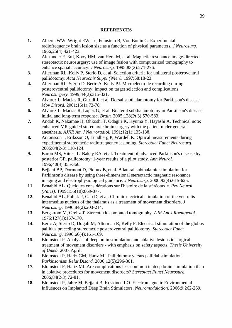
39
REFERENCES
1. Alberts WW, Wright EW, Jr., Feinstein B, Von Bonin G. Experimental radiofrequency brain lesion size as a function of physical parameters. J Neurosurg. 1966;25(4):421-423.
2. Alexander E, 3rd, Kooy HM, van Herk M, et al. Magnetic resonance image-directed stereotactic neurosurgery: use of image fusion with computerized tomography to enhance spatial accuracy. J Neurosurg. 1995;83(2):271-276.
3. Alterman RL, Kelly P, Sterio D, et al. Selection criteria for unilateral posteroventral pallidotomy. Acta Neurochir Suppl (Wien). 1997;68:18-23.
4. Alterman RL, Sterio D, Beric A, Kelly PJ. Microelectrode recording during posteroventral pallidotomy: impact on target selection and complications. Neurosurgery. 1999;44(2):315-321.
5. Alvarez L, Macias R, Guridi J, et al. Dorsal subthalamotomy for Parkinson's disease. Mov Disord. 2001;16(1):72-78.
6. Alvarez L, Macias R, Lopez G, et al. Bilateral subthalamotomy in Parkinson's disease: initial and long-term response. Brain. 2005;128(Pt 3):570-583.
7. Andoh K, Nakamae H, Ohkoshi T, Odagiri K, Kyuma Y, Hayashi A. Technical note: enhanced MR-guided stereotaxic brain surgery with the patient under general anesthesia. AJNR Am J Neuroradiol. 1991;12(1):135-138.
8. Antonsson J, Eriksson O, Lundberg P, Wardell K. Optical measurements during experimental stereotactic radiofrequency lesioning. Stereotact Funct Neurosurg. 2006;84(2-3):118-124.
9. Baron MS, Vitek JL, Bakay RA, et al. Treatment of advanced Parkinson's disease by posterior GPi pallidotomy: 1-year results of a pilot study. Ann Neurol. 1996;40(3):355-366.
10. Bejjani BP, Dormont D, Pidoux B, et al. Bilateral subthalamic stimulation for Parkinson's disease by using three-dimensional stereotactic magnetic resonance imaging and electrophysiological guidance. J Neurosurg. 2000;92(4):615-625.
11. Benabid AL. Quelques considérations sur l'histoire de la stéréotaxie. Rev Neurol (Paris). 1999;155(10):869-877.
12. Benabid AL, Pollak P, Gao D, et al. Chronic electrical stimulation of the ventralis intermedius nucleus of the thalamus as a treatment of movement disorders. J Neurosurg. 1996;84(2):203-214.
13. Bergstrom M, Greitz T. Stereotaxic computed tomography. AJR Am J Roentgenol. 1976;127(1):167-170.
14. Beric A, Sterio D, Dogali M, Alterman R, Kelly P. Electrical stimulation of the globus pallidus preceding stereotactic posteroventral pallidotomy. Stereotact Funct Neurosurg. 1996;66(4):161-169.
15. Blomstedt P. Analysis of deep brain stimulation and ablative lesions in surgical treatment of movement disorders - with emphasis on safety aspects. Thesis University of Umeå. 2007:April.
16. Blomstedt P, Hariz GM, Hariz MI. Pallidotomy versus pallidal stimulation. Parkinsonism Relat Disord. 2006;12(5):296-301.
17. Blomstedt P, Hariz MI. Are complications less common in deep brain stimulation than in ablative procedures for movement disorders? Stereotact Funct Neurosurg. 2006;84(2-3):72-81.
18. Blomstedt P, Jabre M, Bejjani B, Koskinen LO. Electromagnetic Environmental Influences on Implanted Deep Brain Stimulators. Neuromodulation. 2006;9:262-269.

40
19. Blomstedt P, Olivecrona M, Sailer A, Hariz MI. Dittmar and the history of stereotaxy; or rats, rabbits, and references. Neurosurgery. 2007;60(1):198-201.
20. Boertien T, Zrinzo L, Kahan J, et al. Functional imaging of subthalamic nucleus deep brain stimulation in Parkinson's disease. Mov Disord. 2011;26(10):1835-1843.
21. Bradford R, Thomas DG, G.M. B. MRI directed stereotaxic biopsy of cerebral lesions. Acta Neurochir Suppl. 1987;39:25-27.
22. Bucholz RD, Ho HW, Rubin JP. Variables affecting the accuracy of stereotactic localization using computerized tomography. J Neurosurg. 1993;79(5):667-673.
23. Burchiel KJ. Thalamotomy for movement disorders. Neurosurg Clin N Am. 1995;6(1):55-71.
24. Burchiel KJ, Nguyen TT, Coombs BD, Szumoski J. MRI distortion and stereotactic neurosurgery using the Cosman-Roberts-Wells and Leksell frames. Stereotact Funct Neurosurg. 1996;66(1-3):123-136.
25. Carroll CB, Scott R, Davies LE, Aziz T. The pallidotomy debate. Br J Neurosurg. 1998;12(2):146-150.
26. Coenen VA, Madler B, Schiffbauer H, Urbach H, Allert N. Individual fiber anatomy of the subthalamic region revealed with diffusion tensor imaging: a concept to identify the deep brain stimulation target for tremor suppression. Neurosurgery. 2011;68(4):1069-1075.
27. Cooper I. Chemopallidectomy. Science. 1955;121:217-218. 28. Cooper IS, Lee AS. Cryostatic congelation: a system for producing a limited,
controlled region of cooling or freezing of biologic tissues. J Nerv Ment Dis. 1961;133:259-263.
29. Cosman ERs, Cosman ERj. Radiofrequency lesions. In: Lozano A, Gildenberg PL, Tasker R, eds. Textbook of stereotactic and functional neurosurgery. Berlin/Heidelberg: Springer-Verlag; 2009:1359-1382.
30. Dandy WE. Ventriculography following the injection of air into the cerebral ventricles. Ann Surg. 1918;68:5-11.
31. De Salles AA, Brekhus SD, De Souza EC, et al. Early postoperative appearance of radiofrequency lesions on magnetic resonance imaging. Neurosurgery. 1995;36(5):932-936.
32. den Dunnen WF, Staal MJ. Anatomical alterations of the subthalamic nucleus in relation to age: a postmortem study. Mov Disord. 2005;20(7):893-898.
33. DeSalles A, Hariz MI. Magnetic resonance image-guided pallidotomy. In: Rengachary SS, Wilkins RH, eds. Neurosurgical operative atlas. Vol 7. Park Ridge, IL: AANS publications; 1998.
34. Disher B, Lenarduzzi L, Lewis B, Teeuwen J. The history of MRI. http://web2.uwindsor.ca/courses/physics/high_schools/2006/Medical_Imaging/mrihistory.html. 2006.
35. Dogali M, Fazzini E, Kolodny E, et al. Stereotactic ventral pallidotomy for Parkinson's disease. Neurology. 1995;45(4):753-761.
36. Dogali M, Sterio D, Fazzini E, Kolodny E, Eidelberg D, Beric A. Effects of posteroventral pallidotomy on Parkinson's disease. Adv Neurol. 1996;69:585-590.
37. Eriksson O, Backlund EO, Lundberg P, Lindstam H, Lindstrom S, Wardell K. Experimental radiofrequency brain lesions: a volumetric study. Neurosurgery. 2002;51(3):781-787.
38. Eriksson O, Wardell K, Bylund NE, Kullberg G, Rehncrona S. In vitro evaluation of brain lesioning electrodes (Leksell) using a computer-assisted video system. Neurol Res. 1999;21(1):89-95.

41
39. Eskandar E, shinobu L, Counihan TJ, Penney J, Cosgrove GR. Non-microelectrode-guided pallidotomy for Parkinson's disease: Analysis of 73 cases. Neurosurgery. 1997;41:738-739.
40. Fahn S, RL. E, al. e. Unified Parkinson's disease rating scale. In: Fahn S, Marsden CD, Calne DB, eds. Recent developments in parkinson's disease. Vol 2: Florham Park, NJ; 1987:153-163, 293-304.
41. Favre J, taha JM, Baumann TK, Coombs B, szumowski J, Burchiel K. Is MRI accurate enough to perform pallidotomy without microrecording? Neurosurgery. 1996(39):640-641.
42. Favre J, Taha JM, Nguyen TT, Gildenberg PL, Burchiel KJ. Pallidotomy: a survey of current practice in North America. Neurosurgery. 1996;39(4):883-890.
43. Franzini A, Ferroli P, Leone M, Broggi G. Stimulation of the posterior hypothalamus for treatment of chronic intractable cluster headaches: first reported series. Neurosurgery. 2003;52(5):1095-1101.
44. Gerdes JS, Hitchon PW, Neerangun W, Torner JC. Computed tomography versus magnetic resonance imaging in stereotactic localization. Stereotact Funct Neurosurg. 1994;63(1-4):124-129.
45. Gildenberg PL. Confinia Neurologica/Applied Neurophysiology. 50 years. Appl Neurophysiol. 1988;51(1):1-5.
46. Gildenberg PL. The history of stereotactic and functional neurosurgery. In: Gildenberg PL, Tasker R, eds. Textbook of stereotactic and functional neurosurgery: McGraw-Hill; 1996:5-19.
47. Gildenberg PL, Franklin PO. An informal survey of stereotactic and functional neurosurgery. Stereotact Funct Neurosurg. 1994;63(1-4):104-123.
48. Goldman MS, Kelly PJ. Symptomatic and functional outcome of stereotactic ventralis lateralis thalamotomy for intention tremor. J Neurosurg. 1992;77(2):223-229.
49. Gross C, Rougier A, Guehl D, Boraud T, Julien J, Bioulac B. High-frequency stimulation of the globus pallidus internalis in Parkinson's disease: a study of seven cases. J Neurosurg. 1997;87(4):491-498.
50. Guridi J, Gorospe A, Ramos E, Linazasoro G, Rodriguez MC, Obeso JA. Stereotactic targeting of the globus pallidus internus in Parkinson's disease: imaging versus electrophysiological mapping. Neurosurgery. 1999;45(2):278-287.
51. Haines DE. Neuroanatomy: an atlas of structures, sections and systems. Philadelphia: Lippincott Wiliams & Wilkins; 2003.
52. Hardy PA, Bernett GH. Spatial distortion in magnetic resonance imaging: Impact on stereotactic localization. In: Gildenberg PL, Tasker R, eds. Textbook of stereotactic and functional neurosurgery: McGraw-Hill; 1996:271-280.
53. Hardy TL, Bertrand G, Thompson CJ. Position of the medial internal capsular border in relation to third-ventricular width. Appl Neurophysiol. 1979;42(4):234-247.
54. Hariz M. A non-invasive adaptation system for computed tomography-guided stereotactic neurosurgery, Umeå university medical dissertations, new series no. 269, University of Umeå; 1990.
55. Hariz M. CT scanning in stereotactic neurosurgery. In: Gildenberg PL, Tasker R, eds. Textbook of stereotactic and functional neurosurgery: McGraw-Hill; 1996:265-270.
56. Hariz M. Image guided functional ablation of the brain. In: De Salles A, Lufkin R, eds. Minimally Invasive Therapy of the Brain. New York: Thieme; 1997:142-156.
57. Hariz M, Laitinen L. The Laitinen apparatus. In: Gildenberg PL, Tasker R, eds. Textbook of stereotactic and functional neurosurgery: McGraw-Hill; 1996:87-94.
58. Hariz M, Zrinzo A. Globus pallidus stimulation. In: Bain P, Aziz T, Liu X, Nandi D, eds. Deep Brain Stimulation. Oxford: Oxford University Press; 2009:11-18.

42
59. Hariz MI. Correlation between clinical outcome and size and site of the lesion in computed tomography guided thalamotomy and pallidotomy. Stereotact Funct Neurosurg. 1990;54-55:172-185.
60. Hariz MI. Clinical study on the accuracy of the Laitinen CT-guidance system in functional stereotactic neurosurgery. Stereotact Funct Neurosurg. 1991;56(2):109-128.
61. Hariz MI, Bergenheim AT. A comparative study on ventriculographic and computerized tomography-guided determinations of brain targets in functional stereotaxis. J Neurosurg. 1990;73(4):565-571.
62. Hariz MI, Eriksson AT. Reproducibility of repeated mountings of a noninvasive CT/MRI stereoadapter. Appl Neurophysiol. 1986;49(6):336-347.
63. Hariz MI, Fodstad H. Do microelectrode techniques increase accuracy or decrease risks in pallidotomy and deep brain stimulation? A critical review of the literature. Stereotact Funct Neurosurg. 1999;72(2-4):157-169.
64. Hariz MI, Hirabayashi H. Is there a relationship between size and site of the stereotactic lesion and symptomatic results of pallidotomy and thalamotomy? Stereotact Funct Neurosurg. 1997;69(1-4 Pt 2):28-45.
65. Hariz MI, Krack P, Melvill R, et al. A quick and universal method for stereotactic visualization of the subthalamic nucleus before and after implantation of deep brain stimulation electrodes. Stereotact Funct Neurosurg. 2003;80(1-4):96-101.
66. Hassler R, Mundinger F, Riechert T. Stereotaxis in Parkinson Syndrome With an Atlas of the Basal Ganglia. In: Hassler R, ed. Parkinsonism. Berlin: Springer; 1979.
67. Heilbrun MP, Roberts TS, Apuzzo ML, Wells TH, Sabshin JK. Preliminary experience with Brown-Roberts-Wells (BRW) computerized tomography stereotaxic guidance system. J Neurosurg. 1983;59(2):217-222.
68. Hirabayashi H, Hariz M, Fagerlund M. Comparison between stereotactic CT and MRI cordinates of pallidal and thalamic targets using the Laitinen noninvasive stereoadapter. Stereotact Funct Neurosurg. 1998;71:117-130.
69. Hirabayashi H, Hariz M, Wårdell K, Blomstedt P. Impact of parameters of radiofrequency coagulation on volume of stereotactic lesion in pallidotomy and thalamotomy. Stereotact Funct Neurosurg. 2012:In press.
70. Hirabayashi H, Hariz MI, Fagerlund M. Comparison between stereotactic CT and MRI coordinates of pallidal and thalamic targets using the Laitinen noninvasive stereoadapter. Stereotact Funct Neurosurg. 1998;71(3):117-130.
71. Hirabayashi H, Sakaki T, Tsunoda S, et al. Application of MRI to CT guided stereotactic surgery. Stereotact Funct Neurosurg. 1993;32:108-115.
72. Hirabayashi H, Tengvar M, Hariz MI. Stereotactic imaging of the pallidal target. Mov Disord. 2002;17:S130-134.
73. Hitchcock E. Stereotactic-computerized tomography interface device. Appl Neurophysiol. 1987;50(1-6):63-67.
74. Hitchcock E, cadavid J. Third ventricular width and thalamo-capsular laterality. Acta Neurochir Suppl. 1984;33:547-551.
75. Holl EM, Petersen EA, Foltynie T, et al. Improving targeting in image-guided frame-based deep brain stimulation. Neurosurgery. 2010;67(2):437-447.
76. Horsley V, Clarke R. The structure and functions of the cerebellum examined by a new method. Brain. 1908;31:45-124.
77. Hounsfield GN. Computerized transverse axial scanning (tomography). 1. Description of system. Br J Radiol. 1973;46(552):1016-1022.
78. Iacono RP, Lonser RR, Maeda G, et al. Chronic anterior pallidal stimulation for Parkinson's disease. Acta Neurochir (Wien). 1995;137(1-2):106-112.

43
79. Iacono RP, Osborne DR, Nashold BS, Jr. CT analysis of stereotactic thalamotomy. Adv Neurol. 1984;40:453-458.
80. Iacono RP, Shima F, Lonser RR, Kuniyoshi S, Maeda G, Yamada S. The results, indications, and physiology of posteroventral pallidotomy for patients with Parkinson's disease. Neurosurgery. 1995;36(6):1118-1125.
81. Iansek R, Rosenfeld JV, Huxham FE. Deep brain stimulation of the subthalamic nucleus in Parkinson's disease. Med J Aust. 2002;177(3):142-146.
82. Jankovic J, Cardoso F, Grossman RG, Hamilton WJ. Outcome after stereotactic thalamotomy for parkinsonian, essential, and other types of tremor. Neurosurgery. 1995;37(4):680-686.
83. Johansson F, Malm J, Nordh E, Hariz M. Usefulness of pallidotomy in advanced Parkinson's disease. J Neurol Neurosurg Psychiatry. 1997;62(2):125-132.
84. Johansson JD, Blomstedt P, Haj-Hosseini N, Bergenheim AT, Eriksson O, Wardell K. Combined diffuse light reflectance and electrical impedance measurements as a navigation aid in deep brain surgery. Stereotact Funct Neurosurg. 2009;87(2):105-113.
85. Johansson JD, Eriksson O, Wren J, Loyd D, Wardell K. Radio-frequency lesioning in brain tissue with coagulation-dependent thermal conductivity: modelling, simulation and analysis of parameter influence and interaction. Medical & biological engineering & computing. 2006;44(9):757-766.
86. Johansson JD, Loyd D, Wardell K, Wren J. Impact of cysts during radiofrequency lesioning in deep brain structures--a simulation and in vitro study. J Neural Eng. 2007;4(2):87-95.
87. Kelly PJ, Derome P, Guiot G. Thalamic spatial variability and the surgical results of lesions placed with neurophysiologic control. Surg Neurol. 1978;9(5):307-315.
88. Kelly PJ, Gillingham FJ. The long-term results of stereotaxic surgery and L-dopa therapy in patients with Parkinson's disease. A 10-year follow-up study. J Neurosurg. 1980;53(3):332-337.
89. Kessler ML, Pitluck S, Petti P, Castro JR. Integration of multimodality imaging data for radiotherapy treatment planning. Int J Radiat Oncol Biol Phys. 1991;21(6):1653-1667.
90. Kirschman DL, Milligan B, Wilkinson S, et al. Pallidotomy microelectrode targeting: neurophysiology-based target refinement. Neurosurgery. 2000;46(3):613-622.
91. Koller W, Pahwa R, Busenbark K, et al. High-frequency unilateral thalamic stimulation in the treatment of essential and parkinsonian tremor. Ann Neurol. 1997;42(3):292-299.
92. Kondziolka D, Dempsey PK, Lunsford LD, et al. A comparison between magnetic resonance imaging and computed tomography for stereotactic coordinate determination. Neurosurgery. 1992;30(3):402-406.
93. Kondziolka D, Flickinger JC. Use of magnetic resonance imaging in stereotactic surgery. A survey of members of the American Society of Stereotactic and Functional Neurosurgery. Stereotact Funct Neurosurg. 1996;66(4):193-197.
94. Kooy HM, van Herk M, Barnes PD, et al. Image fusion for stereotactic radiotherapy and radiosurgery treatment planning. Int J Radiat Oncol Biol Phys. 1994;28(5):1229-1234.
95. Kopyov O, Jacques D, Duma C, et al. Microelectrode-guided posteroventral medial radiofrequency pallidotomy for Parkinson's disease. J Neurosurg. 1997;87(1):52-59.
96. Krack P, Pollak P, Limousin P, benazzouz A, Benabid AL. Modifications of the stimulation site within Gpi induce different motor effects in parkinsonian patients. Mov Disord. 1997;12:84.

44
97. Krack P, Pollak P, Limousin P, et al. Opposite motor effects of pallidal stimulation in Parkinson's disease. Ann Neurol. 1998;43(2):180-192.
98. Kullberg G, Cronqvist S, Brismar J. Stereotactic lesions studied by computer tomography. Acta Neurochir Suppl. 1980;30:395-400.
99. Kullberg G, Risberg J. Changes in cerebral blood flow after stereotactic thalamotomy. Appl Neurophysiol. 1985;48(1-6):362-366.
100. Laitinen L, Hariz M. Movement disorders. In: Youmans JR, ed. Neurological surgery. 4 ed. Philadelphia: Saunders; 1996:3575-3609.
101. Laitinen L, Liliequist B, Fagerlund M, Eriksson T. An adapter for computed tomography-guided stereotaxis. Surg Neurol. 1985;23:559-566.
102. Laitinen LV. Ventroposterolateral pallidotomy. Stereotact Funct Neurosurg. 1994;62(1-4):41-52.
103. Laitinen LV. Pallidotomy for Parkinson's disease. Neurosurg Clin N Am. 1995;6(1):105-112.
104. Laitinen LV, Bergenheim AT, Hariz MI. Leksell's posteroventral pallidotomy in the treatment of Parkinson's disease. J Neurosurg. 1992;76(1):53-61.
105. Lambert C, Zrinzo L, Nagy Z, et al. Confirmation of functional zones within the human subthalamic nucleus: Patterns of connectivity and sub-parcellation using diffusion weighted imaging. Neuroimage. 2012;60(1):83-94.
106. Leksell L. A stereotaxic apparatus for intracerebral surgery. Acta Chir Scand. 1949;99:229-233.
107. Leksell L, Herner T, Leksell D, Persson B, Lindquist C. Visualization of stereotactic radiolesions by nuclear magnetic resonance. Neurol Neurosurg Psychiat 1985;48:19-20.
108. Lozano A, Hutchison W, Kiss Z, Tasker R, Davis K, Dostrovsky J. Methods for microelectrode-guided posteroventral pallidotomy. J Neurosurg. 1996;84(2):194-202.
109. Lozano AM, Lang AE, Galvez-Jimenez N, et al. Effect of GPi pallidotomy on motor function in Parkinson's disease. Lancet. 1995;346(8987):1383-1387.
110. Lunsford LD. Magnetic resonance imaging stereotactic thalamotomy: report of a case with comparison to computed tomography. Neurosurgery. 1988;23(3):363-367.
111. Maciunas RJ, Fitzpatrick JM, Gadamsetty S, Maurer CR, Jr. A universal method for geometric correction of magnetic resonance images for stereotactic neurosurgery. Stereotact Funct Neurosurg. 1996;66(1-3):137-140.
112. Mandybur G, Morenski J, Kuniyoshi S, Iacono RP. Comparison of MRI and ventriculographic target acquisition for posteroventral pallidotomy. Stereotact Funct Neurosurg. 1995;65(1-4):54-59.
113. May A, Bahra A, Buchel C, Frackowiak RS, Goadsby PJ. Hypothalamic activation in cluster headache attacks. Lancet. 1998;352(9124):275-278.
114. Mayberg HS, Lozano AM, Voon V, et al. Deep brain stimulation for treatment-resistant depression. Neuron. 2005;45(5):651-660.
115. Merello M, Cammarota A, Cerquetti D, Leiguarda RC. Mismatch between electrophysiologically defined and ventriculography based theoretical targets for posteroventral pallidotomy in Parkinson's disease. J Neurol Neurosurg Psychiatry. 2000;69(6):787-791.
116. Michiels J, Bosmans H, Pelgrims P, et al. On the problem of geometric distortion in magnetic resonance images for stereotactic neurosurgery. Magn Reson Imaging. 1994;12(5):749-765.
117. Moringlane JR, Koch R, Schafer H, Ostertag CB. Experimental radiofrequency (RF) coagulation with computer-based on line monitoring of temperature and power. Acta Neurochir. 1989;96(3-4):126-131.

45
118. Mundinger F, Riechert T, Gabriel E. Untersuchungen zu den physikalischen und technischen Voraussetzungen einer dosierten Hochfrequenz-Koagulation bei stereotaktischen Hirnoperationen. Zentralbl Chir. 1960;85:1051-1063.
119. Nakajima T, Zrinzo L, Foltynie T, et al. MRI-guided subthalamic nucleus deep brain stimulation without microelectrode recording: can we dispense with surgery under local anaesthesia? Stereotact Funct Neurosurg. 2011;89(5):318-325.
120. Narabayashi H, Miyashita N, Hattori Y, Saito K, Endo K. Posteroventral pallidotomy: its effect on motor symptoms and scores of MMPI test in patients with Parkinson's disease. Parkinsonism & related disorders. 1997;3(1):7-20.
121. Narabayashi H, Okuma T. Procaine oil blocking of the globus pallidus for the treatment of rigidity and tremor of parkinsonism. Proc JPN Acad. 1953;29:310-318.
122. Narabayashi H, Shimazu H, Fujita Y, Shikiba S, Nagao T, Nagahata M. Procaine-oil-wax pallidotomy for double athetosis and spastic states in infantile cerebral palsy: report of 80 cases. Neurology. 1960;10:61-69.
123. Nashold BS. The history of stereotactic neurosurgery. Stereotact Funct Neurosurg. 1994;62(1-4):29-40.
124. Obrador S, Dierssen G. Cirurgia de la region palidal. Rev Clin Esp Ano XVII. 1956;61:229-237.
125. Olivier A, Bertrand G, Picard C. Discovery of the first human stereotactic instrument. Appl Neurophysiol. 1983;46(1-4):84-91.
126. Ondo WG, Jankovic J, Lai EC, et al. Assessment of motor function after stereotactic pallidotomy. Neurology. 1998;50(1):266-270.
127. Organ LW. Electrophysiologic principles of radiofrequency lesion making. Appl Neurophysiol. 1976;39(2):69-76.
128. Patel NK, Heywood P, O'Sullivan K, Love S, Gill SS. MRI-directed subthalamic nucleus surgery for Parkinson's disease. Stereotact Funct Neurosurg. 2002;78(3-4):132-145.
129. Patel NK, Heywood P, O'Sullivan K, McCarter R, Love S, Gill SS. Unilateral subthalamotomy in the treatment of Parkinson's disease. Brain. 2003;126(Pt 5):1136-1145.
130. Petersen EA, Holl EM, Martinez-Torres I, et al. Minimizing brain shift in stereotactic functional neurosurgery. Neurosurgery. 2010;67(3):213-221.
131. Picard C, Olivier A, Bertrand G. The first human stereotaxic apparatus. The contribution of Aubrey Mussen to the field of stereotaxis. J Neurosurg. 1983;59(4):673-676.
132. Quinn N. Reversal of Parkinson's akinesia by pallidotomy. Lancet. 1994;343(8905):1095-1096.
133. Remy M, Contremoulins M. Le chercheur de projectiles. L'illustration. 1897;55:423. 134. Rezai AR, Phillips M, Baker KB, et al. Neurostimulation system used for deep brain
stimulation (DBS): MR safety issues and implications of failing to follow safety recommendations. Invest Radiol. 2004;39(5):300-303.
135. Richter EO, Hoque T, Halliday W, Lozano AM, Saint-Cyr JA. Determining the position and size of the subthalamic nucleus based on magnetic resonance imaging results in patients with advanced Parkinson disease. J Neurosurg. 2004;100(3):541-546.
136. Roberts DW, Darcey TM, Mamourian A, Lee MJ. Direct stereotactic targeting of the globus pallidus: an MRI-based anatomic variability study. Stereotact Funct Neurosurg. 1995;65(1-4):1-5.
137. Rontgen WC. On a New Kind of Rays. Science. 1896;3(59):227-231. 138. Rontgen WK. A New Form of Radiation. Science. 1896;3(72):726-729.
46
139. Ruzicky E, Sramka M. Mathematical methods using CT and MR images for stereotactic neurosurgery. Mol Chem Neuropathol. 1995;25(2-3):247-254.
140. Saint-Cyr JA, Hoque T, Pereira LC, et al. Localization of clinically effective stimulating electrodes in the human subthalamic nucleus on magnetic resonance imaging. J Neurosurg. 2002;97(5):1152-1166.
141. Schad LR, Bluml S, Debus J, Scharf J, Lorenz WJ. Improved target volume definition for precision radiotherapy planning of meningiomas by correlation of CT and dynamic, Gd-DTPA-enhanced FLASH MR imaging. Radiother Oncol. 1994;33(1):73-79.
142. Schad LR, Boesecke R, Schlegel W, et al. Three dimensional image correlation of CT, MR, and PET studies in radiotherapy treatment planning of brain tumors. J Comput Assist Tomogr. 1987;11(6):948-954.
143. Schaltenbrand G, Bailey P. Introduction to stereotaxis with an atlas of the human brain. Stuttgart: Thieme G; 1959.
144. Schaltenbrand G, Wahren W. Atlas for stereotaxy of the human brain. 2 ed. Stuttgart: Thieme G; 1977.
145. Schrader B, Hamel W, Weinert D, Mehdorn HM. Documentation of electrode localization. Mov Disord. 2002;17 Suppl 3:S167-174.
146. Schuurman PR, de Bie RM, Speelman JD, Bosch DA. Posteroventral pallidotomy in movement disorders. Acta Neurochir Suppl (Wien). 1997;68:14-17.
147. Shannon KM, Penn RD, Kroin JS, et al. Stereotactic pallidotomy for the treatment of Parkinson's disease. Efficacy and adverse effects at 6 months in 26 patients. Neurology. 1998;50(2):434-438.
148. Shima F, Ishido K, Sun SJ, et al. Surgical control of akinesia in Parkinson's disease. Eur Neurol. 1996;36 Suppl 1:55-61.
149. Siegfried J, Lippitz B. Bilateral chronic electrostimulation of ventroposterolateral pallidum: a new therapeutic approach for alleviating all parkinsonian symptoms. Neurosurgery. 1994;35(6):1126-1129.
150. Spiegel EA. Methodological problems in stereoencephalotomy. Confin Neurol. 1965;26(3):125-132.
151. Spiegel EA. History of Human Stereotaxy. In: Schaltenbrand G, Walker AE, eds. Stereotaxy of the human brain. Stuttgart/New York: Georg Thieme Verlag; 1982:3-10.
152. Spiegel EA, Wycis HT, Baird HW. Studies in Stereoencephalotomy. I. Topical relationships of subcortical structures to the posterior commissure. Confin Neurol. 1952;12(3):121-133.
153. Spiegel EA, Wycis HT, Marks M, Lee AS. Stereotaxic apparatus for operations on the human brain. Science. 1947;106:349-350.
154. Spiegelmann R, Chasin S. Postero-ventral pallidotomy: Experience with 100 cases. Neurosurgery. 1996;39:641.
155. Starr PA, Christine CW, Theodosopoulos PV, et al. Implantation of deep brain stimulators into the subthalamic nucleus: technical approach and magnetic resonance imaging-verified lead locations. J Neurosurg. 2002;97(2):370-387.
156. Starr PA, Vitek JL, DeLong M, Bakay RA. Magnetic resonance imaging-based stereotactic localization of the globus pallidus and subthalamic nucleus. Neurosurgery. 1999;44(2):303-313.
157. Struppler A. The history of stereotactic and functional neurosurgery techniques. In: Gildenberg PL, Tasker R, eds. Textbook of stereotactic and functional neurosurgery: McGraw-Hill; 1996:1233-1243.

47
158. Struppler A, Jakob C, Lipinski H-G, Stimmler H. Changes in muscle tone and control of force following stereotactic lesions on motor thalamus level. Mov Disord. 1996;11:241.
159. Sumanaweera TS, Adler JR, Jr., Napel S, Glover GH. Characterization of spatial distortion in magnetic resonance imaging and its implications for stereotactic surgery. Neurosurgery. 1994;35(4):696-703.
160. Sweet WH, Mark VH. Unipolar anodal electrolytic lesions in the brain of man and cat; report of five human cases with electrically produced bulbar or mesencephalic tractotomies. AMA Arch Neurol Psychiatry. 1953;70(2):224-234.
161. Svennilson E, Torvik A, Lowe R, Leksell L. Treatment of parkinsonism by stereotatic thermolesions in the pallidal region. A clinical evaluation of 81 cases. Acta Psychiatr Scand. 1960;35:358-377.
162. Taha JM, Favre J, Baumann TK, Burchiel KJ. Characteristics and somatotopic organization of kinesthetic cells in the globus pallidus of patients with Parkinson's disease. J Neurosurg. 1996;85(6):1005-1012.
163. Taha JM, Favre J, Baumann TK, Burchiel KJ. Tremor control after pallidotomy in patients with Parkinson's disease: correlation with microrecording findings. J Neurosurg. 1997;86(4):642-647.
164. Taha JM, Lamba MA, Samaratunga C, Breneman JC, Warnick RE. A method to reduce systematic spatial shift associated with magnetic resonance imaging. Stereotact Funct Neurosurg. 1996;66(1-3):118-122.
165. Talairach J, David M, Tournoux P, Corredor H, T. K. Atlas d'anatomie stéréotaxique. Paris: Masson; 1957.
166. Talairach JH, M. David, M. Monnier, M. Ajuriaguerra, J. Recherches sur la coagulation therapeutique des structures sous-corticales chez l'homme. Rev Neurol. 1949;8:4-24.
167. Taoka T, Hirabayashi H, Nakagawa H, et al. "Sukeroku sign" and "dent internal-capsule sign"--identification guide for targeting the subthalamic nucleus for placement of deep brain stimulation electrodes. Neuroradiology. 2009;51(1):11-16.
168. Tisch S, Zrinzo L, Limousin P, et al. Effect of electrode contact location on clinical efficacy of pallidal deep brain stimulation in primary generalised dystonia. J Neurol Neurosurg Psychiatry. 2007;78(12):1314-1319.
169. Tsao K, Wilkinson S, Overman J, Koller WC, Batnitzky S, Gordon MA. Pallidotomy lesion locations: significance of microelectrode refinement. Neurosurgery. 1998;43(3):506-512.
170. Walder HA, Jaspar HH. The type of lesion produced in stereotactic operations. Psychiatr Neurol Neurochir. 1970;73(5):353-364.
171. Vale FL, Guthrie BL, Allen K, Argires P, Atchison P. Pallidotomy: Lesion delivery and clinical outcome. Neurosurgery. 1997;41:739.
172. Walton L, Hampshire A, Forster DM, Kemeny AA. A phantom study to assess the accuracy of stereotactic localization, using T1-weighted magnetic resonance imaging with the Leksell stereotactic system. Neurosurgery. 1996;38(1):170-176.
173. vanManen J. Postural instability after ventrolateral thalamic lesions. In: Gillingham FJ, Donaldson IML, eds. Third symposium on Parkinson's disease. Edinburgh: Livingstone; 1969:237-241.
174. Wardell K, Blomstedt P, Richter J, et al. Intracerebral microvascular measurements during deep brain stimulation implantation using laser Doppler perfusion monitoring. Stereotact Funct Neurosurg. 2007;85(6):279-286.
48
175. Vinas FC, Zamorano L, Dujovny M, et al. In vivo and in vitro study of the lesions produced with a computerized radiofrequency system. Stereotact Funct Neurosurg. 1992;58(1-4):121-133.
176. Vitek JL, Bakay RA, Hashimoto T, et al. Microelectrode-guided pallidotomy: technical approach and its application in medically intractable Parkinson's disease. J Neurosurg. 1998;88(6):1027-1043.
177. Vitek JL, Hashimoto T, Baron M, et al. Pallidotomy in Parkinson's disease: Correlation of lesion location to clinical outcome. Mov Disord. 1994;9:477-478.
178. Wyper DJ, Turner JW, Patterson J, et al. Accuracy of stereotaxic localisation using MRI and CT. JNNP. 1986;49(12):1445-1448.
179. Young RF, Vermeulen SS, Grimm P, Posewitz A. Electrophysiological target localization is not required for the treatment of functional disorders. Stereotact Funct Neurosurg. 1996;66 Suppl 1:309-319.
180. Zhu XL, Hamel W, Schrader B, et al. Magnetic resonance imaging-based morphometry and landmark correlation of basal ganglia nuclei. Acta Neurochir (Wien). 2002;144(10):959-969.
181. Zonenshayn M, Rezai AR, Mogilner AY, Beric A, Sterio D, Kelly PJ. Comparison of anatomic and neurophysiological methods for subthalamic nucleus targeting. Neurosurgery. 2000;47(2):282-292.
182. Zrinzo L, Foltynie T, Limousin P, Hariz MI. Reducing hemorrhagic complications in functional neurosurgery: a large case series and systematic literature review. Journal of neurosurgery. 2012;116(1):84-94.
183. Zrinzo L, Yoshida F, Hariz MI, et al. Clinical safety of brain magnetic resonance imaging with implanted deep brain stimulation hardware: large case series and review of the literature. World Neurosurg. 2011;76(1-2):164-172.
184. Zrinzo L, Zrinzo LV, Tisch S, et al. Stereotactic localization of the human pedunculopontine nucleus: atlas-based coordinates and validation of a magnetic resonance imaging protocol for direct localization. Brain. 2008;131(Pt 6):1588-1598.