stepwise design process of guided vehicles
TRANSCRIPT

Paper: ASAT-14-013-GU14th International Conference on AEROSPACE SCIENCES & AVIATION TECHNOLOGY, ASAT - 14 – May 24 - 26, 2011, Email: [email protected] Military Technical College, Kobry Elkobbah, Cairo, Egypt Tel: +(202) 24025292 –24036138, Fax: +(202) 22621908
1
Stepwise Design Process of Guided Vehicles
G.A. El-Sheikh* Abstract: A guided vehicle is mainly divided into four subsystems: the airframe, guidance and control, motor (or propulsion), and payload. Thus, it is a very rich field for the research and interplay of different disciplines with pertinent technologies. Consequently, the first problem facing the designers is to select the technology appropriate for a new vehicle development and for the creation of the conceptual design. In addition, they have to be absolutely sure that the systems they design and develop represent not only the maximum performance for the money invested but also that the type of performance obtained is really needed by the customer. One of the important systems is the guidance and control (the nerve center or backbone) of a vehicle where it is necessary to discuss different design and analysis aspects in addition to analyzing and defining the problems of design and their solutions to cope with different sources of uncertainty. The analysis of the guidance system should include the evaluation of the types of guidance errors and the mathematical methods or tools which exist to evaluate and minimize these errors. The control system synthesis and design should be accomplished using the up-to date techniques such as optimal/adaptive robust techniques in addition to techniques for predicting the system stability and proper system responses. Determination of the sources of errors and their propagation through the system are of fundamental importance in setting design specifications and achieving a well balanced design. Overall evaluation is to be conducted using numerous simulation techniques and test facilities to verify the design, predict performance, define zones of effectiveness, and analyze pre- and post-flight results. Due to the extremely high cost of developing and testing prototype concepts for each of the very large number of possible guidance and control concept combinations, the use of simulation through mathematical techniques is absolute necessity. The results of simulation are then realized and evaluated against the performance requirements. Therefore, this paper is devoted to present the design process in a stepwise approach and to clarify the different disciplines that have to work together towards the production of a guided vehicle starting by the customer requirements and mission. In addition, it is complemented by a comprehensive study of a hypothetical guided vehicle covering both technical and managerial aspects especially those concerning the guidance and control problem. This work solidifies the interplay between different disciplines and will be beneficial for those working in the field especially young researchers and designers. Keywords: Guided Vehicles, Guidance and Control, Optimal and Robust Control
* Professor, [email protected], Tel. 02 0102682402

Paper: ASAT-14-013-GU
2
1. Tactical Missile Design
1.1 Introduction New tactical missile requirements are so stringent that weapon subsystem technology must be utilized at the highest possible level consistent with cost, reliability, and performance. This is particularly true with the guidance and control subsystems, which are the nerve center or backbone of the weapon. As a result of this, there is continuing requirement for more and better tools for analyzing performance, predicting requirements, determining error sources, and selecting suitable concepts. Due to the extremely high cost of developing and testing prototype concepts for each of the very large number of possible guidance and control concept combinations, the use of simulation through mathematical techniques has become an absolute necessity. The results of simulation are then realized and evaluated against the performance requirements. Thus, the objective of this paper is to show the different disciplines that have to work together towards the production of a guided missile starting by the required mission. In addition, it is complemented by a comprehensive study of an air launched guided missile covering both technical and managerial aspects. The challenges facing the guidance engineer/designer are challenges within design and industry and can be summarized as lack of information, ever increasing performance requirements (jamming and target maneuver), complex nature of the underlying system (nonlinear, stochastic, time varying, high order dynamics, and various types of sources for uncertainties within the system) and large envelope of operation. One of the important systems is the guidance and control of a tactical guided missile where it is necessary to discuss different design and analysis aspects in addition to analyzing and defining the problems of design and their solutions. Design engineers must have performance specifications toward which they work to develop designs. Therefore, the mathematical and laboratory techniques that can be used to determine these performance specifications and to predict whether or not a given design will meet a set of specifications are of prime importance. The first problem facing the design/guidance engineer is to select the technology appropriate for a new weapon development and for the creation of the preliminary or conceptual design. The guidance engineers have to be absolutely sure that the systems they design and develop represent not only the maximum performance for the money invested but also that the type of performance obtained is really needed by the customer (armed forces). Therefore, the procedures that are to be followed leading towards the creation of a new weapon capability can be summarized as follows: 1. The operational weapon requirements process begins with identification and assessment of
an operational deficiency or need. The primary goals of the initial assessment of an operational need are to establish a clear understanding of the need and to determine its urgency and importance.
2. The study and analysis efforts consider the mission, threat, operational concepts, constraints, resources and potential alternative proposals.
3. Once the requirements are validated, the proposal then enters another period of study and refinement including possible alternative proposals, cost evaluation, and feasibility in addition to any recommendations.
4. The weapon development process involves extensive additional study, review, hardware prototype building and testing. During the conceptual phase of development, alternative design solution options have to be examined and prepared.

Paper: ASAT-14-013-GU
3
The initial phase of a weapon concept study includes a review for the technical and tactical aspects of the immediate threat, the time frame, mission under investigation, and the present operational capability and inventory problem. A conceptual design concerns developing a preliminary design with performance capabilities reasonably close to those requested. An iteration process is initiated in which performance goals are modified as preliminary designs are iterated and design effectiveness (cost and technical) is estimated. This iteration continues until the development planning management concludes that the study has developed the best series of the alternative designs that can be accomplished in the time provided. The results of these studies formulate the nucleus of new and quantified specifications for either new weapons or for modifications to existing weapons. The resulting data and rationale are continuously reviewed and examined by appropriate higher-level authority until decisions are made for program continuation. Upon approval of a tactical guided missile program for development of hardware test items, the system specifications as well as several subsystem specifications are successively defined and evolve as tradeoffs made between performance, cost, risk availability, manufacturing difficulty, environmental limits, and reliability. The conceptual development of a tactical guided missile designs includes several subsystems such as propulsion, warhead, flight control, guidance and airframe. The guidance and navigation systems are often further subdivided into mid-course and terminal for the purpose of high precision. The guidance system analysis should include the evaluation of the types of guidance errors and the mathematical methods or tools which exist to evaluate and minimize these errors. The control system synthesis and design should be accomplished using the up-to date techniques such as optimal/adaptive robust techniques in addition to techniques for predicting the system stability and proper system responses. The guidance analysis methodologies lead to the development of guidance and navigation laws. The real proving ground for the guidance theory and for testing the guidance and control ideas and designs is the analogue/digital computer then using the field or flight tests.
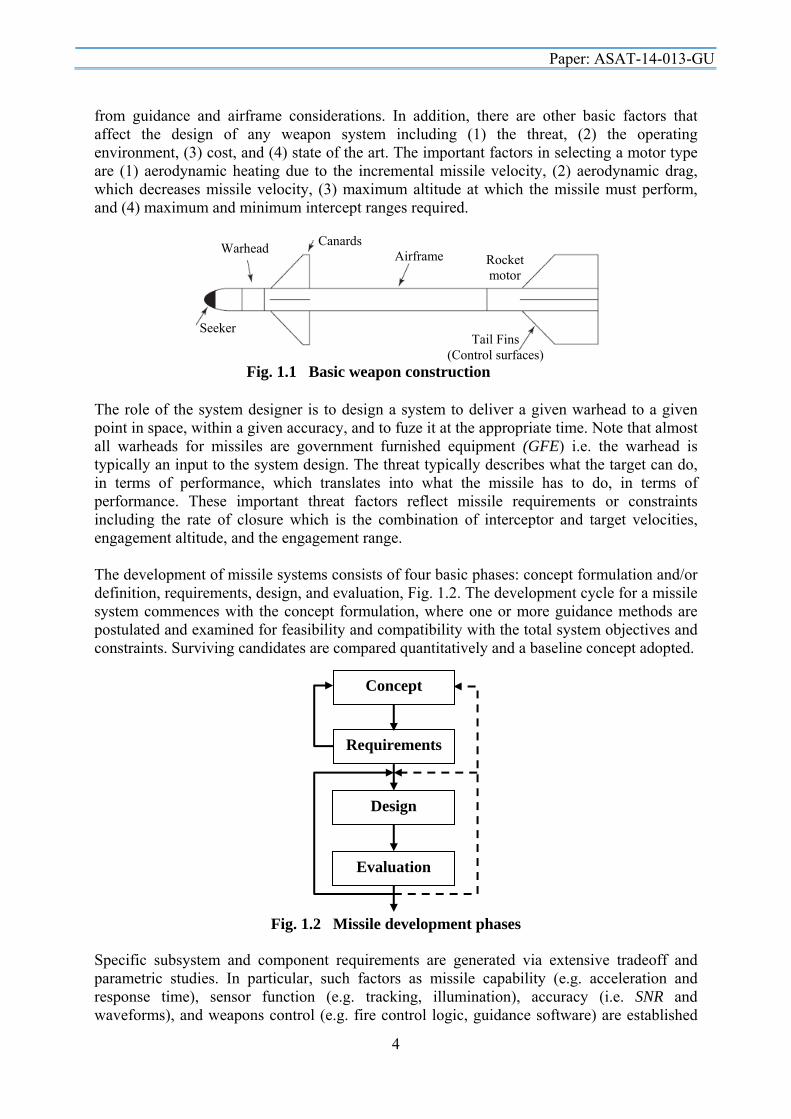
1.2 Design Phases A missile can be defined as an aerospace vehicle with varying guidance capabilities that is self-propelled through space for the purpose of inflicting damage on a designated target. These vehicles are fabricated for air-to-air, air-to-surface, surface-to-air, or surface-to-surface roles. They contain a propulsion system, warhead section, guidance systems, and control surfaces, although hypervelocity missiles do not use warheads or control surfaces. The guidance capabilities of the different missiles vary from self-guided to complete dependence on the launch equipment for guidance signals. A guided missile is typically divided into four subsystems (Fig. 1.1): the airframe, guidance, motor (or propulsion), and warhead. The type and size of airframe is strongly dependent on guidance characteristics, motor size, and warhead size. Guidance or Avionics is the means by which a missile steers or is steered to a target and its type is also dependent on the motor, warhead, and threat. More specifically, the type of guidance chosen is dependent on the overall weapon system in which the missile will be used, on the type of threat against which the missile will be used, the characteristics of the threat target, and other factors. The motor characteristics are dependent on guidance requirements, the threat, and the airframe characteristics. The warhead is dependent on the threat and type of guidance. Commonly, the procedure is to size the guidance requirements (e.g., accuracy, response time, range capability) from the threat, select an airframe that can deliver the required aerodynamic performance, size the motor based on threat and airframe considerations, and size the warhead
Paper: ASAT-14-013-GU
4
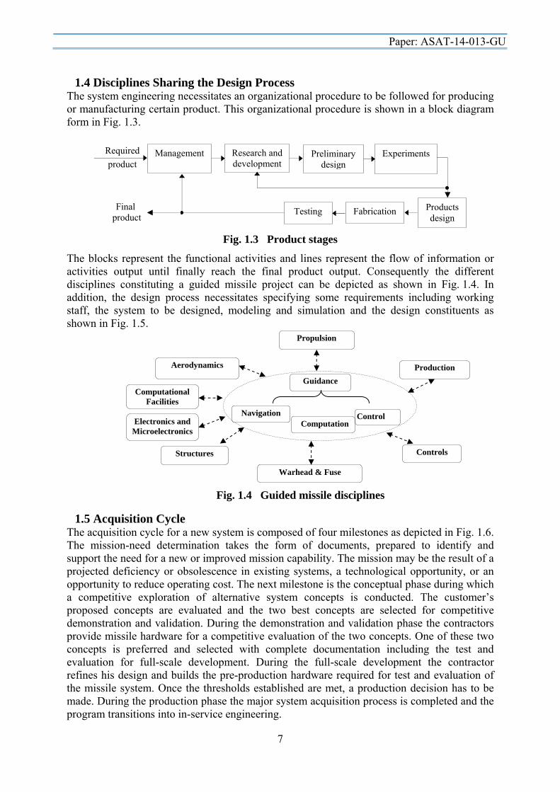
from guidance and airframe considerations. In addition, there are other basic factors that affect the design of any weapon system including (1) the threat, (2) the operating environment, (3) cost, and (4) state of the art. The important factors in selecting a motor type are (1) aerodynamic heating due to the incremental missile velocity, (2) aerodynamic drag, which decreases missile velocity, (3) maximum altitude at which the missile must perform, and (4) maximum and minimum intercept ranges required. The role of the system designer is to design a system to deliver a given warhead to a given point in space, within a given accuracy, and to fuze it at the appropriate time. Note that almost all warheads for missiles are government furnished equipment (GFE) i.e. the warhead is typically an input to the system design. The threat typically describes what the target can do, in terms of performance, which translates into what the missile has to do, in terms of performance. These important threat factors reflect missile requirements or constraints including the rate of closure which is the combination of interceptor and target velocities, engagement altitude, and the engagement range. The development of missile systems consists of four basic phases: concept formulation and/or definition, requirements, design, and evaluation, Fig. 1.2. The development cycle for a missile system commences with the concept formulation, where one or more guidance methods are postulated and examined for feasibility and compatibility with the total system objectives and constraints. Surviving candidates are compared quantitatively and a baseline concept adopted. Specific subsystem and component requirements are generated via extensive tradeoff and parametric studies. In particular, such factors as missile capability (e.g. acceleration and response time), sensor function (e.g. tracking, illumination), accuracy (i.e. SNR and waveforms), and weapons control (e.g. fire control logic, guidance software) are established
Fig. 1.1 Basic weapon construction
Seeker
Rocket motor
Tail Fins (Control surfaces)
Canards Warhead Canards Airframe
Fig. 1.2 Missile development phases
Concept
Requirements
Design
Evaluation

Paper: ASAT-14-013-GU
5
by means of both analytical and simulation techniques. After iteration of the concept/ requirements phases, the analytical design is initiated. The guidance law is refined and detailed, a missile autopilot and the accompanying control actuator are designed, and an onboard sensor tracking and stabilization system devised. This design phase entails the extensive use of feedback control theory and the analysis of nonlinear, nonstationary dynamic systems subjected to deterministic and random inputs. Determination of the sources of errors and their propagation through the system are of fundamental importance in setting design specifications and achieving a well balanced design. Finally, overall evaluation is conducted using numerous simulation techniques and test facilities to verify the design, predict performance, define zones of effectiveness, and analyze post-flight results. Classical servomechanism theory has been used extensively to design both hydraulic and electric seeker servos that are compatible with requirements for gyro-stabilization and fast response. Pitch, yaw, and roll autopilots have been designed to meet problems of Mach variation, altitude variation, induced roll moments, instrumentation lags, body-bending modes, guidance response, and stability. Although classical theory presently is most applicable to autopilots and airframe stability, research efforts are continually made to apply modern control and estimation theory to conventional as well as adaptive autopilot design. Modern advanced guidance and control systems having superior performance have been designed with on-line Kalman filter estimation for filtering noisy radar data and with optimal control gains expressed in closed form. Synthesis of sampled data homing and command guidance systems are being used extensively today. For example, a vital point in the development of advanced homing guidance and control systems is to optimize the performance of the missile under design for various intercept situations and target maneuvers. Furthermore, trends in operational requirements indicate that future air-to-air or air-to ground missiles should have high kill probability under total sphere launch engagement conditions in addition to launch and leave capability when employed against highly maneuverable intelligent targets. In order to satisfy these requirements, future air-to-air missiles require complex guidance algorithms which require more information about the missile and target dynamic states that should be accurately measured or estimated onboard the missile. The nature of this problem motivates the use of modern\ advanced control theory to derive the advanced guidance laws and modern estimation theory to develop techniques to process the available information. The key to a successful problem formulation is a translation of the mission requirements into a mathematical performance index (P.I.). No matter what theoretical techniques are used to develop the optimal control strategy, they will always be based on the minimization (or maximization) of some performance index. Hence, the optimal control strategy will be no better than the selection of the critical performance drivers and the translation of these into concise mathematical terms. In addition to the performance index, two other formulations will impact the optimal control strategy, namely, the mathematical model of the system and the additional equality and inequality constraints to be placed on the system. In general, a more detailed system model results in a more accurate control strategy, but this is achieved at the expense of additional complexity in both the derivation and resulting algorithms. The selection of appropriate equality/inequality constraints can be based upon either actual system parameters or trajectory properties that the optimal solution should possess. Some of the modern control techniques that have been investigated and/or applied are (1) reachable set theory, (2) singular perturbation theory, (3) differential game theory, (4) robust control theory and (5) adaptive control theory.

Paper: ASAT-14-013-GU
6
The performance index (cost functional) study is a fundamental but extremely complex problem as the choice of the parameters/states constituting the performance index is influenced by the mission objectives and the interrelationships of the steps involved in the modern control problem formulation. Specifically, for every different performance index or cost functional there is a different optimal guidance law, the measure of its performance will be the ability of the missile to hit the target (e.g. minimum terminal miss distance) in various engagement scenarios. Additional measures of performance involve (1) launch envelope (full 360◦ launch aspect angle, minimum inner launch boundary), (2) fuel considerations, (3) time considerations, and (4) maneuver capability. Any research and development project involves a great deal of risk due to different factors. The expected areas of risk in missile design could be arranged due to their complexity and sensitive response as follows: seeker, built-in intelligence, avionics, motor and propellant, materials and technologies, and missile and launcher interface. However, the objective worth going through the design process in addition that the risk could be minimized through the following: (1) efficient management control through integrated software packages for task follow-up and budget control, (2) mathematical modeling to reduce both cost and risk involved, (3) real CAD-CAM systems to ensure quick response and interaction between different departments/disciplines, and (4) qualified and highly skilled personnel.
1.3 Simulation and Emulation Usually the emulators and simulators are used for the testing of new architectures and also to give training in some complex systems. A most famous example for a simulator is the flight simulator that simulates the functionalities of an aircraft or guidance system. A simulator is a piece of software that duplicates as precisely as possible some process in almost all the possible ways so you can run your code to see if it is correct. Usually simulators are developed for new architectures to test them out before it is committed to reality. Occasionally, a vendor will let customer have access to the simulator to help speed development for that architecture. Simulation is generally used when we have some mathematical models of the original system and want to know the output for a given set of inputs. The simulation results can be verified via situations that are close as possible to reality and working environments. An emulator is a piece of hardware which duplicates the features and functions of a real system, so that it can behave like the actual system and it can be used for tests i.e. it involves special hardware to facilitate the emulation. One system is said to emulate another when it performs in exactly the same way (same output for same input under similar conditions but the mechanism to arrive at the output from the input is different), though perhaps not at the same speed. A typical example would be the emulation of onboard computer by (a program running on) a pc. You might use emulation as a replacement for a system whereas you would use a simulation if you just wanted to analyze it and make predictions about its performance. Emulation is generally used when we do not exactly know the internal mechanism of the original system but are familiar with the input/output pattern. For example, neural networks may be used to emulate different systems. Neural networks are trained to produce the same output for the same input as that of the original system though the mechanism/procedure to generate the output are quite different.
Paper: ASAT-14-013-GU
7
1.4 Disciplines Sharing the Design Process The system engineering necessitates an organizational procedure to be followed for producing or manufacturing certain product. This organizational procedure is shown in a block diagram form in Fig. 1.3.
The blocks represent the functional activities and lines represent the flow of information or activities output until finally reach the final product output. Consequently the different disciplines constituting a guided missile project can be depicted as shown in Fig. 1.4. In addition, the design process necessitates specifying some requirements including working staff, the system to be designed, modeling and simulation and the design constituents as shown in Fig. 1.5.
1.5 Acquisition Cycle The acquisition cycle for a new system is composed of four milestones as depicted in Fig. 1.6. The mission-need determination takes the form of documents, prepared to identify and support the need for a new or improved mission capability. The mission may be the result of a projected deficiency or obsolescence in existing systems, a technological opportunity, or an opportunity to reduce operating cost. The next milestone is the conceptual phase during which a competitive exploration of alternative system concepts is conducted. The customer’s proposed concepts are evaluated and the two best concepts are selected for competitive demonstration and validation. During the demonstration and validation phase the contractors provide missile hardware for a competitive evaluation of the two concepts. One of these two concepts is preferred and selected with complete documentation including the test and evaluation for full-scale development. During the full-scale development the contractor refines his design and builds the pre-production hardware required for test and evaluation of the missile system. Once the thresholds established are met, a production decision has to be made. During the production phase the major system acquisition process is completed and the program transitions into in-service engineering.
Fig. 1.3 Product stages
Management Research and development
Preliminary design
Experiments
Products design
Fabrication Testing Final product
Required
product
Guidance
Propulsion
Aerodynamics Production
Structures Controls
Warhead & Fuse
Navigation Computation
Control
Computational Facilities
Electronics and Microelectronics
Fig. 1.4 Guided missile disciplines

Paper: ASAT-14-013-GU
8
Fig. 1.5 Layout of Design Process Requirements
Systems Control Activities
Define System Requirements
Develop Mathematical Model
System Design
Development Tests
Structural Proving
Reliability Proving
Environmental Proving
Performance Proving
Compatibility tests Lab testing Anechoic tests Carry trials Firing trials
Modeling over the full performance
envelope Staff Requirements
The test and evaluation includes three basic issues with documents: the operational requirements, the decision coordinating paper/integral program summary, and the test and evaluation master plan. The operational requirements are considered as the reference for comparison of achievement throughout the design and production program and it is a basis for designing test and evaluation plans. The decision coordinating paper/integral program summarizes the acquisition planning for the system’s life cycle and provides a management overview of the program. This document is a basis for reviews and consequently the areas defining risks and performance should be given attention in the test and evaluation process to ensure the availability of necessary data for review. The third issue is the test and evaluation master plan which contains the integrated requirements for development test and evaluation, operational test and evaluation, and the schedule and resources, required for accomplishment. It is prepared early in the program and approved prior to milestone-1. In addition, it is updated and revised at regular intervals to maintain currency and provide the necessary details for each program phase. The cost of developing a major weapon has become so expensive that joint developments or joint programs are potentially more cost effective. In addition, the
Conceptual Demonstration and Validation
Full-Scale Development
Production
Mission need determination
Fig. 1.6 The acquisition cycle
5-6 1 year 1-4
Milestone-0 Milestone-1 Milestone-2 Milestone-3

Paper: ASAT-14-013-GU
9
Contractor development/production of research, development, test, and evaluation assets - Missiles - Weapon system - Launchers - Test and support equipment
Contractor test and evaluation
Government development test and evaluation
Operational evaluation
Fig. 1.7 Full-scale development
5-6 years 2-3 years
Milestone-2 Milestone-3
Missile assets delivery
continuing emphasis for technology development and reduced program cost motivates the need for competitive programs. The test and evaluation is divided into three distinct categories: development test and evaluation, operational test and evaluation, and production acceptance test and evaluation. Development test and evaluation is performed by service field activities to assist in the engineering and development process and define the overall missile system capabilities. It is used to provide a technical database and determine whether the design goals for each program phase have been achieved and when the program should progress through each phase into production. Operational test and evaluation is conducted to estimate a missile system’s operational effectiveness and suitability. It is performed in a simulated tactical environment using fleet-type operators and maintenance personnel. It is conducted by a specified operational group that is independent of the development activity and responds to a higher level of command. The results obtained are the basis for production recommendation and provide material used in operating instructions, software documentation, publications and handbooks used by the operational personnel. Production acceptance test and evaluation is performed on production items to determine if the requirements of the production contract have been met. It should insure that the concept is realistic and minimizes the cost. Reliability demonstration testing is performed on production-lot missiles to formally demonstrate missile and launcher mean time between failures (MTBF). Government lot acceptance testing is performed to insure that the desired quality is maintained throughout long-term production. The end objective of the major system acquisition process is the satisfactory deployment and utilization of the missile system in a tactical environment. The two primary indicators of the degree of successful deployment/utilization are (1) the kill probability and (2) the percentage of total assets available to support tactical operations. There are several critical areas of interest that contribute to assets availability and probability of kill including missile performance, weapon system integration, reliability, avionics, training, environment, and production. The test and evaluation involvement begins at the time a new program is initiated and continues throughout the life cycle of the weapon system. The test and evaluation plan includes inputs related to test plans and objectives, assets, test locations, schedules, budgets, participation and responsibilities. The test and evaluation activities in addition to its maturity increase from phase to another. Upon satisfying the milestone-2 requirements and selecting a contractor, the program moves into the full scale development which require 5 to 6 years for completion and consists of four parts as depicted in Fig. 1.7. Government development test and evaluation defines the missile system capabilities for determining if the missile system has demonstrated sufficient capabilities to proceed to operational evaluation. The operational evaluation results provide an insight into usefulness of the system in an operational environment. That is, they determine if the missile is suitable for the operational environment and if the system should proceed into production.

Paper: ASAT-14-013-GU
10
The test data and information resulting from the above tests form the basis for recommending for or against production of the missile system via obtaining sufficient data within schedule and assets constraints. Once the missile system is introduced into service, test and evaluation is performed in support of software and hardware configuration control, evaluation of product improvements and engineering change proposals, and evaluation of problem areas detected in the operational environment. The goals of missile system test and evaluation are achieved through the proper use of all the means of test and analysis at hand. The most desirable test and evaluation approach is to use realistic flight tests to produce the required technical data. However, this is not practical for all missile systems due to the high cost of the missile, the cost to conduct a flight test, and the program. Therefore, the desired conditions or environment can be represented in a laboratory environment and consequently other test techniques can be conducted to complement the data available from launches. The flight tests provide proof of performance and data for validation of different testing techniques. The bulk of the data required to determine missile capabilities is obtained from captive flights, laboratory/field tests, and analytical and hardware-integrated simulations. 2. Stages of the Design Process In view of the previous discussions, the design process can be described in stages as shown in Fig. 2.1. The mathematical modeling together with the development rounds and firing trials should constitute the evidence necessary to support the guided weapon system release to service.
Systems Performance
Conceptual Design
Customer Requirements
Configuration Definition
Overall System Definition Technical requirements
Specifications Mandatory standards Safety requirements Contract requirements
Design Definition
Integration and Evaluation
Production
Design Proving
Technical requirements
and subsystems configurations
Design data Integration and
evaluation data
Evaluation data
Acceptance Criteria
Product certification
Consultation on Safety Design Producability Cost
Design test data Test specifications Acceptance criteria
Product data Production engineering
Fig. 2.1 Stages of the Design Process

Paper: ASAT-14-013-GU
11
2.1 Customer Requirements The customer requirements include the following points: (1) scenario of weapon or the purpose of the missile with short details/restrictions imposed upon it, (2) scenario of action or the nature of mission and required intelligence, (3) environmental conditions the developed missile should withstand, (4) safety i.e. the developed missile should be completely secured during storing, handling and launching, and (5) expected missile lifetime during which the missile has to be reliable.
2.2 System Specifications The guided weapon layout is shown in Fig. 2.2 according to which the missile specifications include the following issues: Purpose, Launching, Type of guidance, Type of motor, Level of intelligence, Warhead, Fuse, Method of control, Initial conditions for guidance, Used actuators, ECM resistant, Environmental conditions, Reliability and maintainability. The launcher includes suspension, installation and missile interface and release while the ground\parent support equipments include transportation, lifting, mounting and testing means.
2.3 Design Specifications The missile configuration includes missile integrity, missile configuration and missile c.g. The missile performance covers the velocity profile (initial velocity and final velocity), the range, the working altitude from sea-level, the maneuverability (forward and lateral accelerations) and the field of view. Missile aerodynamics include the control method (thrust vector or aerodynamic surfaces), aerodynamic control surfaces (tail, canard, wing controls, wingless tail control, or tailless control), the nose profile (aerodynamic, guidance and radiation requirements), tail-end profile (motor nozzle and tail-end drag), wing profile (speed, maneuverability, c.p. and moments), and the missile total drag (missile incidence and speed). The propulsion unit includes the propulsion unit (speed, acceleration and range), the type of propellant, the motor performance, and dimensions (missile mass, outer diameter, required acceleration, burning time, impulse, propellant density, and volumetric efficiency). The flight mechanics include the missile control loop, Fig. 2.3, the missile static stability, and missile stability, controllability and maneuverability.
Guided Weapon
Launcher Missile Ground\Parent Support
Structure Motor Navigation Warhead & Fuse Avionics SeekerAutopilot
Fig. 2.2 Guided weapon layout
Fig. 2.3 Missile control loop
Guidance head Navigation
system (PN)
Fin servoFilter Missile dynamics
Missile acceleration and angular rates
Missile position
Noise
Target position
Double Integration

Paper: ASAT-14-013-GU
12
The guidance and control include the guidance method (command, homing, combined or combined and TVM), radar type (CW, simple pulsed, pulse Doppler, Pulse compression, frequency agile, MTI, Monopulse, or phased array), the guidance and control loop and the mathematical modeling and simulation of flight. The warhead, fuse and safety arming mechanism (SAU) include the warhead design, the missile fusing system (contact fuse, proximity fuse, fuse electronics and processing, and the firing circuit), and the safety and arming unit (to prevent the warhead arming until the missile becomes at a safe distance from launching site). The missile airframe includes the missile forebody (radome, the front forebody, the guidance assembly and the rear forebody), the missile aftbody (front aftbody, lap-joints, the rear aftbody containing the rocket motor and fins), the missile wings and the control fins. The missile/launcher interface includes the effect of missile on the launcher, the effect of launcher on the missile and the types of missile launching (gravity drop, rail launch, tube launch, ejection release).
2.4 Development Once the configuration and missile system performance start to crystallize; a mathematical model for the missile should be developed for simulating its performance throughout the flight envelope. The mathematical modeling is important due to the following reasons: reduction of development costs via verifying the reliability of the conceptual hardware design with a minimum number of expensive field tests and giving answers to questions concerning different targets. The mathematical modeling is a continuous operation starting from product concept through product life cycle to product evolution. Therefore, it can be divided into the following types: (1) enemy threat evaluation and formulation of guided weapon system requirements, (2) feasibility study and formulation of design specifications, (3) research and development of models for new technology, (4) pre- and post-flight trials, (5) system evaluation, and (6) product development and evolution. The missile mathematical model breaks down into sub-branches: kinematics, dynamics (aerodynamics, motor, gravity), homing head, navigation, and autopilot (electronics, instruments, actuators). The development rounds are essential for design verification and optimization and they are divided into the following types: ballistic rounds, aerodynamic rounds, propulsion rounds, fuse and warhead rounds, guidance rounds, and system rounds. The firing trials are carried out to demonstrate that the system is really does operate as required and expected. The data from these trials have to be compared with the mathematical model performance characteristics for updating and refining the model as necessary.
2.5 Customer Support The customer support concerns the test and maintenance equipments and details, the manuals and technical publications and documents that should be delivered with the system covering the purpose and planning information, operating manual, technical manuals, and service manuals. The test and maintenance operations/equipments required for the missile system should cover the maintenance levels down to the fourth level. The first level covers the required tests before and after installing the missile on the launcher concerning the integrity between the missile and launcher tests and missile overall performance test. The second level is devoted to repair and test parts of the system in addition to checking the whole system. The third level represents the repair and test of the modules of each part of the missile using most of the test equipments used with the second level. The fourth level covers the sub-assemblies of each module where they are to be replaced, repaired and tested using extra test equipments and installations.

Paper: ASAT-14-013-GU
13
The required information is used to assess the suitability of the missile for use and the logistic support required for such use. This information covers the purpose, shape/size/weight, performance, environmental data, packaging/transportation, associated equipments, and power requirements for the designed system. The operating manual contains the information required to operate the system safely with maximum efficiency including brief description, controls and manual instruments, unpacking, pre-start checks, in operation, and destruction. Technical manuals contain the information on the technical principles of design, how the system functions and the inter-relations between different functions. Therefore, this technical description covers the mechanical/hydraulics, electrical / electronic and safety including hazards and warnings. The service manual provides information on fault diagnosis, repair, inspection and calibration of the system that are necessary to achieve acceptable level of operating efficiency. Therefore, it is divided into failure diagnosis (defect investigation), repair, inspection standard (how and what to inspect) and calibration.
2.6 Research and Development Program The system engineer together with his team should put down a rough estimate for the time period and number of staff necessary for each activity in the design process. In addition, the inter-relations and dependencies between different activities should be taken into considerations.
2.7 Cost Estimate Being the research and development program had specified in terms of time and personnel, an estimate for the total cost can be calculated. That is, a rough estimate for the cost can be obtained depending upon the required manpower related to the time period and number of staff presented in the previous item for each activity in the design process.
2.8 Research and Design Schedule The time table clarifying the stages for research and design program within five years can be depicted as shown in the following table:
Activity 1st year 2nd year 3rd year 4th year 5th year Customer requirements 3 System specifications 3 Missile initial configurations 1 Missile c.g. estimation 1 Missile performance 1 Missile aerodynamics 3 Rocket motor 3 Flight mechanics 3 Guidance and initial control loop 9 Avionics 6 Warhead 4 Safety arming unit 3 Fusing 3 Airframe design 6 Missile integrity 6 Missile launcher interface 3 Test equipments specifications 6 Mathematical modeling 30 Development rounds 30 Flight trials 30 System test and Maintenance Equipments 12 Manuals and technical publications 6 Total 16 45 57 36 18

Paper: ASAT-14-013-GU
14
Note that the time duration in this table is expressed in month and the mathematical modeling covers the whole period of work. The manpower required for the research and design program can be summarized as follows:
Activity Months Personnel Men Month Customer requirements 3 5 15 System specifications 3 12 36 Missile configuration 1 3 3 Missile c.g. estimation 1 2 2 Missile performance 1 3 3 Missile aerodynamics 3 3 9 Rocket motor 3 3 9 Flight mechanics 3 2 6 Guidance and control loop 9 5 45 Avionics 6 3 18 Warhead 4 2 8 Safety arming unit 3 2 6 Fusing 3 2 6 Airframe design 6 3 18 Missile integrity 6 5 30 Missile launcher interface 3 2 6 Test equipments specifications 6 4 24 Mathematical modeling 30 4 120 Development rounds 30 4 120 Flight trials 30 3 90 System test and Maintenance Equipments 12 3 36 Manuals and technical publications 6 2 12 Total 77 622
3. Test and Evaluation of Tactical Missile Systems Test and evaluation provides the means for determining to what extent the weapon satisfies its requirements, how well it functions in the operational environment, and whether or not it should continue into production.
3.1 System Tests Performance evaluation techniques include three main types: preliminary tests, simulation tests, and flight tests. The preliminary tests include (1) analytical study to review and understand technical documents, schematics, and other materials to the extent of complete system understanding, and (2) laboratory/field tests concerning the operation of the system or subsystems in a controlled open-loop laboratory or field environment to define specification data, threshold data, and basic subsystem performance. The simulation might be analytical (the 6DOF trajectory simulation, the guidance and autopilot synthesis and the seeker with lethality simulation) and\or hardware integrated (integrating as much of the missile hardware as possible in place of analytical models to yield necessary sophistication and realism); the analytical concerns the mathematical representation of the missile system/subsystems in closed loop operation while the hardware integrated is a closed-loop representation of the missile system for evaluating its performance as affected by guidance/seeker/signal processing. The flight tests may be captive carry tests (open loop configuration) where the missile is carried aloft into a representative environment (i.e. live targets, countermeasures, chaff, clutter) or launches where the missile is launched in a realistic representative environment which is the desirable data sources.

Paper: ASAT-14-013-GU
15
3.2 Test and Evaluation of Guidance System The test process of a guidance system is devoted to handle the following main points: (1) missile information base {Air-to-Surface (AS), Air-to-Air (AA), Surface-to-Air (SA) or Surface-to- Surface (SS)}, (2) performance measures, (3) quantitative and qualitative measures, and (4) decision making and global evaluation. Accordingly, the characteristics and parameters of guided missile systems can be summarized to include general information and purpose, boundary for launching zone, boundary of killing zone, type of guidance system, guidance methods, homing head, frequency of operation, capabilities of killing, missile characteristics, method of missile control, and the guidance system. The evaluation can be carried through tailoring certain criterion with different weightings for the corresponding missile characteristics and parameters. The values of these weights can be selected\tuned online for flexibility of evaluation as possible.
3.3 Testing and Calibration of Inertial Navigation Systems To establish their suitability for a given application, inertial sensors have to go through an evaluation testing process and ensure that they satisfy all the performance requirements of that application. Inertial sensors are usually designed and manufactured to be used within a wide range of applications such as ships, submarines, aircraft, space vehicles, and missiles in addition to wide range of operating environments. Testing and calibration methods should reflect the type of application and the environment in which they are required to operate. The behavior or performance of an inertial sensor can be represented mathematically with expressions having some variables obtained from testing and calibration. Having established the performance figures, or characterized the sensor, any systematic errors may be compensated for leading to enhance its accuracy. The testing process of a sensor can be categorized into three types: qualification, acceptance and reliability tests. The qualification tests are intended to show that a particular design will meet the requirement of a customer with adequate margins for production tolerances. The acceptance tests are undertaken on sensors (each sensor or a sample of sensors) during production in order to check selected parameters and to establish data for the calibration of the sensors. While, the reliability tests involve a sample of sensors selected at random running under normal operating conditions to establish the mean time between failures (MTBF).
3.3.1 Testing procedure The test and investigation procedure may be carried through either static or dynamic methods. In a static test the device is kept fixed and the response to some natural effect or phenomenon is observed. For example, the specific force due to Earth’s gravity could be observed or measured with an accelerometer in various orientations. In a dynamic test the device under test is moved and its response to that disturbance is monitored and compared with the stimulus. Therefore, the performance of a sensor can be characterized through three steps: (1) coarse checking in which a very simple tests are conducted, such as a single stationary position test on a bench, to establish that the device response is compatible with the designer’s or manufacturer’s predictions, (2) static testing in which multi-position tests are conducted to the device for deriving its performance parameters, and (3) dynamic testing in which the device is subjected to controlled motion such as angular rotations or linear movements with acceleration that necessitates specialized test equipments such as rate turn- or vibrating-tables.
3.3.2 Test equipment Testing of inertial sensors and/or INS necessitates the availability of a specialized laboratory with sophisticated test equipment that can be isolated from shocks, vibrations and other

Paper: ASAT-14-013-GU
16
perturbations induced by the local environment. For example, the temperature of the environment can be carefully controlled by utilizing special computer controlled cabinets. Therefore, the application of digital computers to the testing process is essential for precise equipment control and data analysis. To enable the application of a given and known stimulus to a sensor/system and then observe its response for analysis, the testing schedule and procedure must be matched with the application requirements and the testing equipment should have sufficient accuracy and precision. In addition, the data acquisition system and the processing algorithms have to be compatible with the anticipated accuracy of either the sensor or its application. Therefore, the test equipment should be regularly calibrated, otherwise their performance will degrade and contribute error measurements obtained by the sensors under test and leading to erroneous interpretations. The form of acquired signals is dependent upon the type of sensors, their pick-offs and the nature of any rebalance loops utilized. These signals may be in the form of d.c. current or a.c. current continuous or pulsed type and consequently the utilized measuring instruments should be capable of observing any type of signals accurately and precisely including various transient effects. For which reason a programmable multi-meter, a programmable oscilloscope and a programmable spectrum analyzer are to be used within the loop of testing procedure, which preferred to be completely computerized. That is, the control computer can be used to control the motion of test equipment, conduct the required test, collect the required data and analyze to extract any required information.
3.3.3 Gyroscope and accelerometer testing Procedures for testing various types of gyroscopes and accelerometers can be found in the IEEE standards. The gyroscopes to be tested are usually mounted in a test fixture, often a cube with very accurately machined faces for achieving very precise mounting in the test equipment. This enables the sensor to be transferred between the various pieces of test equipment used in a test program and maintaining its mounting accuracy precisely and allows various designs of sensor to be tested on the same equipment. Prior to conducting a series of tests for evaluating the gyroscope performance, it is usual to undertake some preliminary investigations such as: (1) measurement of electrical resistance and insulation strength, (2) polarity, (4) time for the rotor to reach its operating speed, (4) time to stop rotating and (5) power consumption. The performance of an accelerometer is usually investigated using a series of static and dynamic test procedures similar to those for a gyroscope. However, a reduced scale of testing is required to characterize the performance of the accelerometer. For example, rate table testing is generally unnecessary and the multi-position tests are undertaken using a precision dividing head to apply small accelerations along the accelerometer input axis. This head has a setting accuracy of about one second of arc and enables the sensitive/input axis of an accelerometer to be rotated w.r.t. the gravity vector. Hence, the component of gravity acting along the input axis of the accelerometer may be varied very precisely. For a pendulous accelerometer, care should be used during its mounting to ensure that whenever possible the hinge axis is not vertical for avoiding the effects of frictional forces in the hinge upon the output signals. Before conducting a series of tests to evaluate the performance of an accelerometer, preliminary tests are usually undertaken to ensure that the accelerometer is functioning as designed by the manufacturer. Typical tests include observation of the output for a short period (10-20 minutes) after switch-on to check the warm-up trends and the determination of the threshold acceleration level which produces output signal.

Paper: ASAT-14-013-GU
17
4. Technology Transfer and Cooperation For high kill probability and safety of parent launchers\sites, most of the unguided weapons can be modified\guided using either homing guidance or autonomous guidance systems. The autonomous guidance systems utilize mainly INS or INS aided GPS, for example. These modifications yield precise guidance and consequently higher kill probability in addition to larger ranges which preserve the safety for the parent aircrafts. A stabilized platform is necessary to be utilized within a guided aerospace vehicle, for example a guided bomb, to decouple its movements from that of the vehicle body around its c.g. The stabilized platform may be an inertial stabilized platform or a closed loop stabilized platform, each of which has its pertinent bottlenecks. The stabilized platform maintains the original or required orientation with the help of servo actuators and feedback gyros with tachometers regardless the weapon movements. This stabilized platform can be utilized with any of the seeker technologies including IIR, Radio, TV, or Laser or the INS. The field of cooperation includes the research and manufacturing of either a guided vehicle or modifying one of the available systems via certain subsystem such as INS, guidance and control or seeker. The mechanism of execution includes the cooperation with a professional side in this area, which believed that they reached good results through researches and developments of this subject. In addition, they are able to supply the critical technologies concerning any of the intended points. This cooperation should be hand-by-hand between researchers of the two sides during the design and production phases. Therefore, each of the two sides has to carry on some of the preliminary activities: visibility studies for the points of cooperation, documenting the technical specifications for the required system. System engineers, specialized in the design, development and production of the required points of cooperation, have to visit the first side to discuss the visibility study, the technical specifications, the manufacturing and the present system structure. Manufacturing a prototype of the required system and specifying its test should be carried out with the attendance of specialized system engineers from the viewpoints of physical, mechanical and electrical characteristics in addition to specifying the devices required to carry on the test. 5. Case Study This case study is devoted to design and analyze the performance of a guided missile with the following characteristics: air launched, radius of action is 45 [km], wide band of flight and weather conditions, resistance to electronic counter measures (ECM), active homing with proportional navigation guidance, double base solid propellant rocket motor of constant burning rate, aerodynamically controlled giving the possibility of interception even after motor shut-off, and radar proximity fuze triggers a preformed fragmentation warhead within lethal range.
5.1 Customer Requirements The customer requirements include: the scenario of weapon is to develop a counter missile to self-protect an early warning aircraft (EWAC), the total system weight should not exceed 750 [kg], the scenario of action concerns the worst case facing the EWAC being attacked by two missiles launched at the same time from the enemy aircraft, the environmental conditions, the developed missile should be completely secured during storing, handling and launching, and the expected lifetime during which the missile has to be reliable.

Paper: ASAT-14-013-GU
18
5.2 System Specifications The guided weapon /vehicle layout is shown in Fig. 2.2 and, according to requirements, the missile specifications are summarized as follows: anti-missile, air launched, fire and forget active homing using proportional navigation guidance method, solid rocket motor, moderate level of built-in intelligence, fragmentation warhead, proximity fuse, aerodynamically controlled, initial guidance conditions are supplied by the EWAC before launch, hydraulic actuators electrically controlled, ECM resistant, all weather, and high reliability and maintainability. Concerning the launcher, only two missiles are assumed to be carried by the parent aircraft and have the following specifications: suspended beneath fuselage, staggered installation and missile interface and release i.e. jettison release. In addition, the ground support equipments should include: transportation, lifting, mounting, and testing means.
5.3 Design Specifications
5.3.1 Missile configuration To reduce the aerodynamic interference between wings and fins, they are interdigitated i.e. they are rotated 45° with respect to each other as shown in Fig. 5.1, and the missile slenderness ratio (L/D) is 15.6. In addition, the hypothetical designed missile configuration and integrity is demonstrated in Fig. 5.2a and the approximate mass distribution and c.g. estimation are shown in Fig. 5.2b. The wings are located in the centre body near to the missile c.g. and they are controlled via hydraulic actuators while the fixed stability fins are placed around the tail pipe of the engine and they are located well to the rear to give large stabilizing moments and to avoid roll control problems. The length is m=390 [cm], weight W=300 [kg], diameter d=25 [cm] and c.g. location to rear cg =161 [cm].
5.3.2 Missile performance The missile velocity against time is shown in Fig. 5.3 and the designed system performance is characterized as: velocity profile (mach 0.6 - 3.9), range or radius of action 45 [km], working altitude from sea-level to 15 [km], maneuverability (forward 30 [m/sec2] and lateral accelerations 40 g), and field of view equals 20.
5.3.3 Missile Aerodynamics The choice of control and shape of aerodynamic surface are governed by missile aerodynamics and general engineering aspects including control method, aerodynamic surface controls, nose profile, tail-end profile, wing profile, and missile total drag. The choice of control method to control a missile in flight might be thrust vector, or aerodynamic surfaces. In this case study the missile is decided to be controlled aerodynamically because its entire flight envelope is within the dense atmosphere with high speed which results in considerable aerodynamic forces via slight deflections of the control surface. In addition, the rocket motor will shut-off at missile speed about mach 4 at which the missile kinetic energy is high and consequently it will still be controllable that results in extension of missile range.
Fig. 5.1 Wings and Fins Interdigitation
45°
Wing Fin

Paper: ASAT-14-013-GU
19
The aerodynamic surface controls can be selected from the five conventional types shown in Fig. 5.4, which might be tail, canard, wing, wingless tail, or tailless control. The tail control (fixed wings and moving tail controls) is the most common form in which the control units together with the actuators are placed at the rear to give large control moments for small surface deflections. In this configuration, the control surface deflections are opposite to the desired lateral movements. In canard control (fixed wings) configuration, the control surfaces are very effective because they do not work in wakes and they are placed well forward to give large control moments. Unlike the tail control, the control deflections are in the same sense as the body angle of attack. The main disadvantage of this layout is that the wake from the canard will act on the wings resulting in poor roll control.
Fig. 5.2a The designed missile configuration and integrity
Wing Fin
Seeker Proximity
Fuze Autopilot Igniter Rocket Motor
Radome Fuze antenna
Warhead
Power supply and actuator
units
Fig. 5.2b The approximate mass distribution and c.g. estimation
0 5 10 15 20 25 30 350.5
1
1.5
2
2.5
3
3.5
4
4.5
Time [sec]
Vel
ocity
[M
ach]
Fig. 5.3 Missile velocity profile

Paper: ASAT-14-013-GU
20
Wing control Canard control
Rear control Wingless Rear control
Rear control Tailless control
Body extension control Nose flap control
Fig. 5.4 Aerodynamic surface controls
Wing control configuration is not common but has the advantage of minimum body incidence with tail surfaces are placed well to the rear to avoid the roll control problem. The major disadvantage of wing control is its need for large power source to be capable of moving the large inertia wings. Besides, the wing profile should be thickened at the midchord to accommodate for the control shaft transmitting the moments which increases the drag. Wingless tail control configuration is more suitable when control is provided by non-aerodynamic means e.g. thrust vector. Therefore, it is usually used in ballistic missiles where the tail surfaces are used for stability purposes only rather than maneuverability and the body lift is aerodynamically sufficient. Tailless control configuration has the advantage of removing the interference between wings and tails but its dominant disadvantage is the difficulty of actuating the wing flaps.
According to the above discussions and the design requirements, the chosen configuration is the movable wings with fixed fins. Since the propulsion unit does not allow enough room for actuators in the rear of the missile, moving wings are used with hydraulic actuators which are electronically controlled. The wings are placed very close to the missile c.g. ahead of which the wing c.p. is arranged. The wing profile can be thickened at its midchord taking the double wedge cross-sectional shape to ease manufacturing process. The fixed fins are mounted at the rear to provide large stabilized moments required for supersonic operation.
Concerning the wing profile, high speed and high maneuverability dictate a low aspect ratio and consequently a delta platform is used due to the small movement of the C.P. with incidence and flight speed. The wing profile is taken to be a double-wedge cross-section to accommodate the control shaft transmitting the moments with the variation of axial force coefficient Cx at zero incidence and the total drag with respect to the flight mach number. It is clear that Cx increases dramatically as M approaches unity due to formation of shock waves on the surface and beyond M=1, Cx reduces slowly while the total drag force continues to increase due to the increase in flight speed.
The nose shape must satisfy the requirements concerning aerodynamics that necessitate slender conical shape to cope with operation at supersonic speeds, guidance which need enough room for the guidance equipment and radiation which need minimum dissipation and energy refraction. Practically, the nose shape should be a compromise between conical and blunted cone shape with moderate amount of blunting to reduce the nose drag. The tail-end profile has minimum base area dictated by the motor nozzle area and it usually has either a blunt base or a boat-tail depending on the equipment fitted at the tail and on missile overall length restriction.

Paper: ASAT-14-013-GU
21
5.3.4 Propulsion Unit The propulsion unit in a guided weapon system propels the missile to home on its designated target and consequently the design necessitates choice of propulsion unit, type of propellant, motor performance and dimensions. The choice of propulsion unit is governed factors including: speed, acceleration, maneuver, range and weight. For subsonic applications, the ramjet cannot be used and consequently the choice is between rockets and gas turbines. For short ranges, the rocket will be lighter and smaller and is generally the best choice while for subsonic and long range applications the gas turbines are much lighter and smaller. For supersonic applications, the choice is generally solid rockets or ramjets depending on the range. For supersonic and long range applications, the choice is between turbofans and liquid propellant rockets where the rocket motor gives rapid acceleration and high thrust/weight ratio. The intended missile is characterized by supersonic, rapid acceleration, high thrust/weight ratio and short/medium range. Consequently, the best choice is the solid rocket propulsion unit which has the advantage of operating at any altitude and any speed. In addition, it is characterized by the ease and safety in handling, reliable, inexpensive and small case mass. The necessary motor performance parameters and dimensions include missile mass, outer diameter, required acceleration, burning time, impulse, propellant density, volumetric efficiency and thrust profile. The hypothetical data include: missile mass = 300 [kg], missile outer diameter = 0.25 [m], required acceleration =30 [m/sec2], burning time = 34 [s], specific impulse per unit mass = 2450 [N-s/kg], specific impulse per unit volume = 4.29 × 10⁶ [N-s/m3], propellant density =1750 [kg/m3], volumetric efficiency (assumed) = 0.95, and the thickness of the motor case = 5 [mm]. To take account for the variation of missile mass during flight, the burning time is divided into 340 equal intervals each of 0.1[s]. For each interval, the propellant mass is calculated and hence the final missile mass is calculated at the end of the interval which is considered as the initial mass of the next interval, Fig. 5.5. From the performance analysis, it is seen that the motor mass/missile ratio is a function of required acceleration, burning time and the propellant specific impulse per unit mass. Thus, once the missile mission and the propellant are determined, this ratio is fixed (0.6 in this case). Practically, this ratio varies considerably with the propulsion type from zero for mortars to 0.7 for long range missiles. According to the previous discussions, the propulsion unit may be a solid rocket motor with propellant mass =130.4 [kg], motor mass =182.6 [kg], motor length =1.73 [m], cast double base (CDB) propellant and star grain shape with constant burning rate.
0 5 10 15 20 25 30 35160
180
200
220
240
260
280
300
Time [sec]
Mis
sile
Mas
s [k
g]
0 5 10 15 20 25 30 350
20
40
60
80
100
120
140
Time [sec]
Con
sum
ed P
rope
llant
Mas
s [k
g]
Fig. 5.5 Missile mass and propellant mass versus burning time

Paper: ASAT-14-013-GU
22
5.3.5 Flight Mechanics The missile control loop is the interface between the guidance system and the aerodynamic forces created on the control surfaces. The control system allows getting high accurate missile response to the guidance loop demand and it is considered as an inner loop inside the guidance loop as shown in Fig. 2.3. Proportional navigation (PN) is used to minimize the dispersion and lateral acceleration (LATAX) during the terminal phase. The missile dynamics describes its response with some shaping in the input and its stability could be achieved through optimum design via conditional constraints on the gain and phase margins. An autopilot is used to achieve stability over a wide range of operating conditions, where the wing servo of the control loop is a hydraulic one because of its high response and large power. Concerning the missile static stability, it is worthy to note that the slope of Cmcg/CN is equal to the static margin (dCmcg /dCN = static margin). Therefore, for the missile to be statically stable, this slope should be –ve i.e. an increase in CN (or ) will result in a decrease in Cmcg. This means that to achieve static stability, the static margin should be –ve i.e. the aerodynamic centre of pressure (cp) of the complete missile should lie aft its centre of gravity (cg). From Fig. 5.6 it is seen that if the cp is ahead of the cg, then will tend to increase i.e. the missile is unstable. On the other hand, if the cp is aft the cg, will tend to decrease i.e. the missile is statically stable. The missile stability is its ability to return to its original condition following a small disturbance and it is dependent on the position of aerodynamic centre (cp) with respect to the centre of gravity (cg). The distance between these two centers is called the static margin. The ac varies with the missile attitude and tail fin setting while the cg varies as the fuel is used up during flight. A careful balance has to be achieved to keep the stability to an acceptable level in all phases of flight. Static margins are typically less than 5% of the overall missile length. The static stability of the designed system is achieved by keeping the missile c.g. ahead of its ac, Fig. 5.6. In addition, the change in the static margin is kept minimum to minimize the
Cmcg
α
+ve slope (unstable)
Cmcg
α
-ve slope (stable)
Fig. 5.6 Missile stability
N
x m
c.g.
VM c.p
c
cN (a)
Cmcg
Cmcg
N
x m
c.g.
VM
c.p
cN (b)
c
Paper: ASAT-14-013-GU
23
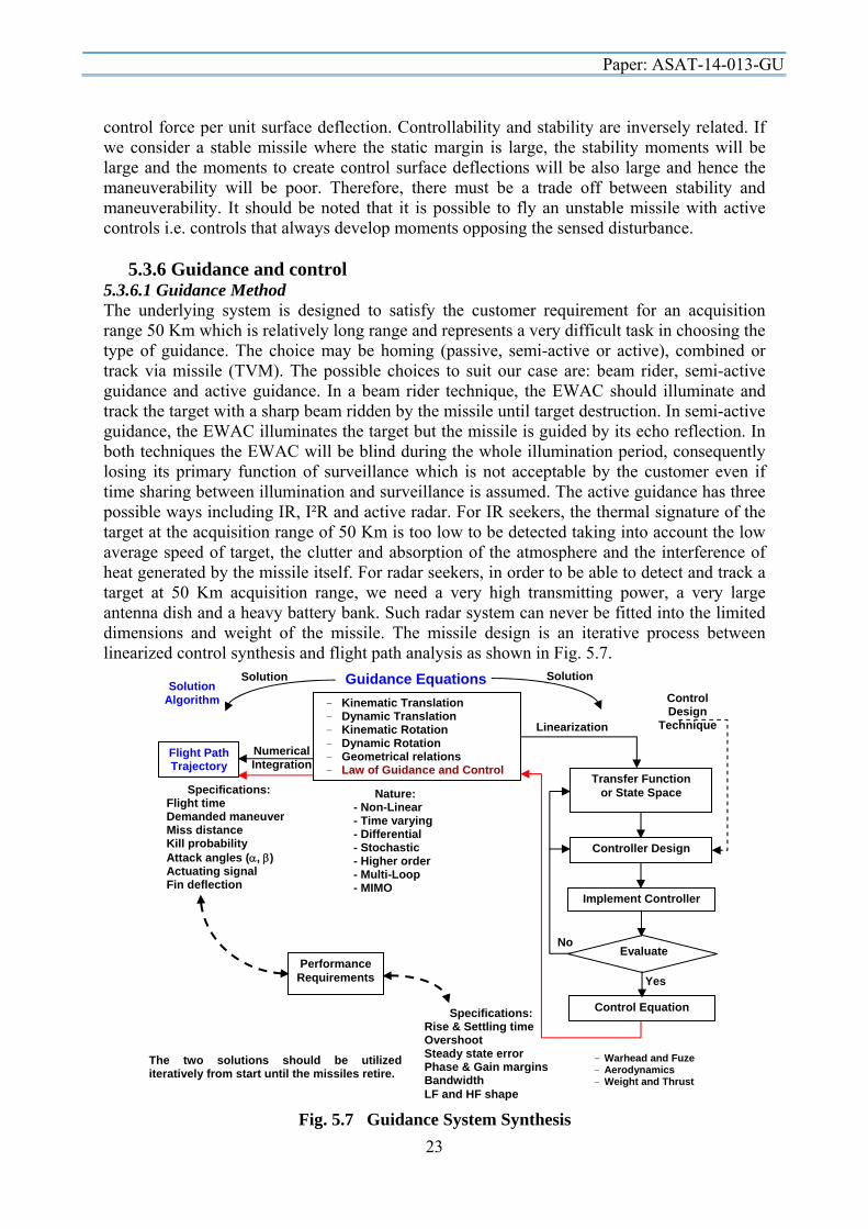
- Kinematic Translation - Dynamic Translation - Kinematic Rotation - Dynamic Rotation - Geometrical relations - Law of Guidance and Control
Nature: - Non-Linear - Time varying - Differential - Stochastic - Higher order - Multi-Loop - MIMO
Numerical Integration
Flight Path Trajectory
Specifications: Flight time Demanded maneuver Miss distance Kill probability Attack angles (, ) Actuating signal Fin deflection
Linearization
Transfer Function or State Space
Controller Design
Implement Controller
Evaluate
Control Design
Technique
No
Control Equation
Yes
Performance Requirements
Specifications: Rise & Settling time Overshoot Steady state error Phase & Gain margins Bandwidth LF and HF shape
Guidance Equations Solution Solution
The two solutions should be utilized iteratively from start until the missiles retire.
Solution Algorithm
- Warhead and Fuze - Aerodynamics - Weight and Thrust
Fig. 5.7 Guidance System Synthesis
control force per unit surface deflection. Controllability and stability are inversely related. If we consider a stable missile where the static margin is large, the stability moments will be large and the moments to create control surface deflections will be also large and hence the maneuverability will be poor. Therefore, there must be a trade off between stability and maneuverability. It should be noted that it is possible to fly an unstable missile with active controls i.e. controls that always develop moments opposing the sensed disturbance.
5.3.6 Guidance and control 5.3.6.1 Guidance Method The underlying system is designed to satisfy the customer requirement for an acquisition range 50 Km which is relatively long range and represents a very difficult task in choosing the type of guidance. The choice may be homing (passive, semi-active or active), combined or track via missile (TVM). The possible choices to suit our case are: beam rider, semi-active guidance and active guidance. In a beam rider technique, the EWAC should illuminate and track the target with a sharp beam ridden by the missile until target destruction. In semi-active guidance, the EWAC illuminates the target but the missile is guided by its echo reflection. In both techniques the EWAC will be blind during the whole illumination period, consequently losing its primary function of surveillance which is not acceptable by the customer even if time sharing between illumination and surveillance is assumed. The active guidance has three possible ways including IR, I²R and active radar. For IR seekers, the thermal signature of the target at the acquisition range of 50 Km is too low to be detected taking into account the low average speed of target, the clutter and absorption of the atmosphere and the interference of heat generated by the missile itself. For radar seekers, in order to be able to detect and track a target at 50 Km acquisition range, we need a very high transmitting power, a very large antenna dish and a heavy battery bank. Such radar system can never be fitted into the limited dimensions and weight of the missile. The missile design is an iterative process between linearized control synthesis and flight path analysis as shown in Fig. 5.7.
Paper: ASAT-14-013-GU
24
Considering the above mentioned discussion, it is obvious that the ultimate choice is active guidance using a radar seeker provided we can overcome the problem of acquisition range. This can be achieved by using the following reasoning: Before launch, the surveillance radar of EWAC detects the angular position of the raid
missile and feeds it to the homing head of designed missile via a servo link. The designed missile will fly approximately straight following the predefined heading,
independently from the seeker, until a closing distance within the acquisition range of the on-board radar is reached.
The seeker radar is active during all flight time, but its output will be comparable to noise until we reach the predetermined threshold value corresponding to 15 [Km]. The signal detected at that distance will be amplified and used to energize a relay which pulls the seeker into the guidance and control loops.
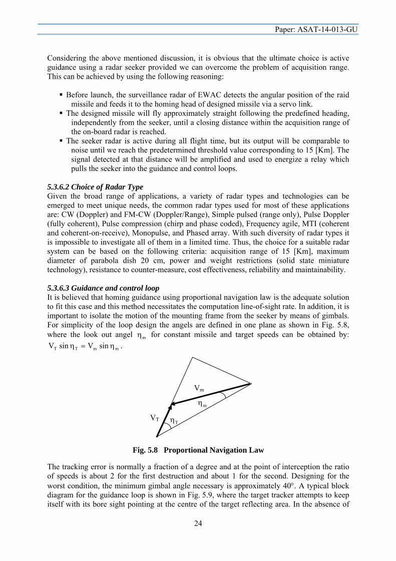
5.3.6.2 Choice of Radar Type Given the broad range of applications, a variety of radar types and technologies can be emerged to meet unique needs, the common radar types used for most of these applications are: CW (Doppler) and FM-CW (Doppler/Range), Simple pulsed (range only), Pulse Doppler (fully coherent), Pulse compression (chirp and phase coded), Frequency agile, MTI (coherent and coherent-on-receive), Monopulse, and Phased array. With such diversity of radar types it is impossible to investigate all of them in a limited time. Thus, the choice for a suitable radar system can be based on the following criteria: acquisition range of 15 [Km], maximum diameter of parabola dish 20 cm, power and weight restrictions (solid state miniature technology), resistance to counter-measure, cost effectiveness, reliability and maintainability. 5.3.6.3 Guidance and control loop It is believed that homing guidance using proportional navigation law is the adequate solution to fit this case and this method necessitates the computation line-of-sight rate. In addition, it is important to isolate the motion of the mounting frame from the seeker by means of gimbals. For simplicity of the loop design the angels are defined in one plane as shown in Fig. 5.8, where the look out angel m for constant missile and target speeds can be obtained by:
mmTT sin Vsin V . The tracking error is normally a fraction of a degree and at the point of interception the ratio of speeds is about 2 for the first destruction and about 1 for the second. Designing for the worst condition, the minimum gimbal angle necessary is approximately 40. A typical block diagram for the guidance loop is shown in Fig. 5.9, where the target tracker attempts to keep itself with its bore sight pointing at the centre of the target reflecting area. In the absence of
Fig. 5.8 Proportional Navigation Law
VT T
Vm
m

Paper: ASAT-14-013-GU
25
any base motion, the supply voltages to the tracking motors could be used as a measure of the antenna steady state angular rates and for perfect servos the antenna rates will always be equal to the sight line rates. In practice, of course, there will be a dynamic lag in the antenna following the sight line. The proportional navigation constant N is chosen to be 3< N <6 (Fig. 5.10) and this is the optimum range since as N increase the homing accuracy is improved at the expense of system stability. On the other hand as N decreases the stability increases at the expense of homing accuracy. For designed missile field of view (20), we can easily neglect the term ( mcos )
and approximate ( mmtan ), where m is the difference between sightline direction and missile axis. The flight is controlled by the autopilot which turns commands from the seeker into movements of the wings with one pair providing pitch control and the orthogonal pair providing roll control, the latter being backed up by a roll rate gyro. 5.3.6.4 Mathematical modeling and flight simulation Computer programs have to be built for stimulating trajectory and collision course for interception of target (enemy missile) with the EWAC and interception of designed missile with that target at different modes of operations. The results obtained from conducting this simulation should be plotted and analyzed for tuning the guidance loop parameters as depicted in Fig. 5.7.
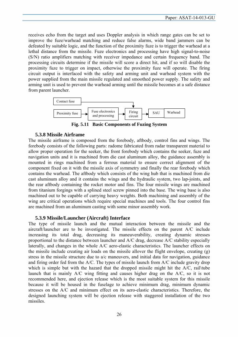
5.3.7 Warhead, Fuse and Safety Arming Mechanism (SAM) The warhead is used to destroy the target and consequently it consists of a high explosive charge surrounded by a casing in which preformed fragments are contained. The casing absorbs part of the energy produced by the pressure impulse and converts it into kinetic energy carried by the fragments. The details of warhead design can be found in the pertinent literature. Technical requirements imposed upon the fuzing system are: must sense the target, warhead detonation point must match the warhead performance and the interception condition, must demonstrate immunity to spurious/premature operation, and must be reliable. The basic components sketched in Fig. 5.11 include contact\proximity fuze, electronics and processing, and the firing circuit. The proximity fuze may be active of the radar type which
Fig. 5.9 Guidance Loop
Seeker Servo (G/s)
Rate Gyro (Kg)
Receiver K
Integrator (1/s)
Head Rate ( s )
To Autopilot ( )
Target T Error Angle
Error Rate
Fig. 5.10 Integrated guidance and autopilot
Actuator Servos Filter Missile
dynamics
Acceleration Error
Acceleration
Body Rate
+-Guidance
Vc
m
C
cos
V N
mtan
m
+-
Bias corresponding to initial angle and compensation
Paper: ASAT-14-013-GU
26
receives echo from the target and uses Doppler analysis in which range gates can be set to improve the fuze/warhead matching and reduce false alarms, wide band jammers can be defeated by suitable logic, and the function of the proximity fuze is to trigger the warhead at a lethal distance from the missile. Fuze electronics and processing have high signal-to-noise (S/N) ratio amplifiers matching with receiver impedance and certain frequency band. The processing circuits determine if the missile will score a direct hit, and if so will disable the proximity fuze to trigger on impact, otherwise the proximity fuze will operate. The firing circuit output is interfaced with the safety and arming unit and warhead system with the power supplied from the main missile regulated and smoothed power supply. The safety and arming unit is used to prevent the warhead arming until the missile becomes at a safe distance from parent launcher.
5.3.8 Missile Airframe The missile airframe is composed from the forebody, aftbody, control fins and wings. The forebody consists of the following parts: radome fabricated from radar transparent material to allow proper operation for the seeker, the front forebody which contains the seeker, fuze and navigation units and it is machined from die cast aluminum alloy, the guidance assembly is mounted in rings machined from a ferrous material to ensure correct alignment of the component fixed on it with the missile axis of symmetry and finally the rear forebody which contains the warhead. The aftbody which consists of the wing hub that is machined from die cast aluminum alloy and it contains the wings and the hydraulic system, two lap-joints, and the rear aftbody containing the rocket motor and fins. The four missile wings are machined from titanium forgings with a splined steel screw pinned into the base. The wing base is also machined out to be capable of carrying heavy weights. Both machining and assembly of the wing are critical operations which require special machines and tools. The four control fins are machined from an aluminum casting with some minor assembly work.
5.3.9 Missile/Launcher (Aircraft) Interface The type of missile launch and the mutual interaction between the missile and the aircraft/launcher are to be investigated. The missile effects on the parent A/C include increasing its total drag, decreasing its maneuverability, creating dynamic stresses proportional to the distance between launcher and A/C drag, decrease A/C stability especially laterally, and changes in the whole A/C aero-elastic characteristics. The launcher effects on the missile include creating air loads on the missile allover the flight envelope, creating (g) stress in the missile structure due to a/c maneuvers, and initial data for navigation, guidance and firing order fed from the A/C. The types of missile launch from A/C include gravity drop which is simple but with the hazard that the dropped missile might hit the A/C, rail\tube launch that is mainly A/C wing fitting and causes higher drag on the A/C, so it is not recommended here, and ejection release which is the most suitable system for this missile because it will be housed in the fuselage to achieve minimum drag, minimum dynamic stresses on the A/C and minimum effect on its aero-elastic characteristics. Therefore, the designed launching system will be ejection release with staggered installation of the two missiles.
Fig. 5.11 Basic Components of Fuzing System
Contact fuse
Proximity fuse Fuse electronics and processing
Firing circuit
Warhead SAU

Paper: ASAT-14-013-GU
27
5.4 Development and Customer Support The mathematical modeling together with the development rounds and firing trials should constitute the evidence necessary to support the guided weapon system release to service. Once the configuration and missile system performance start to crystallize; a mathematical model for the missile should be developed to be used for simulating the missile flight throughout its performance envelope. The mathematical modeling is indispensable due to the following reasons: reduction of development costs of a missile by contributing to prove the reliability of the conceptual hardware design with a minimum number of expensive field tests, and giving answers to questions concerning different targets. The mathematical modeling is a continuous operation starting from product concept and going through product life cycle to product evolution. Therefore, it can be divided into the following types: enemy threat evaluation and formulation of guided weapon system requirements, feasibility study and formulation of design specifications, research and development of models for new technology, pre- and post-flight trials, system evaluation, and product development and evolution. The test and maintenance operations/equipments required for the missile system should cover the maintenance levels down to the four levels presented in Section 2.5. Manuals and technical publications include documents that should be delivered with the system covering the purpose and planning information, operating manual, technical manuals, service manual, maintenance schedule, parts catalogues and related information and modification and general instructions (Section 2.5). The purpose and planning information are required to assess the suitability of the missile for use and the logistic support required for such use. The maintenance schedule describes the work planned to be done on the system at stated intervals of time, running hours or completed operations. Concerning parts catalogues and related information, the document contains lists and illustrations for the system, assemblies, sub-assemblies and components with associated list of parts plus part numbers and stock numbers. It should be designed as an aid to the identification of parts and demanding of spares. The modification and general instructions document describes how to incorporate modifications into the system and how to test the equipment after installation. Concerning the research and development program, the system engineer together with his team should put down a rough estimate for the time period and number of staff necessary for each activity in the design process. In addition, the inter-relations and dependencies between different activities should be taken into considerations. The time table clarifying the stages of research and design program for five years can be depicted as shown in Section 2.8.
5.5 Cost Estimate Manpower Calculation: Being the research and development program had specified in terms of time and personnel, an estimate for the total cost can be calculated. That is, a rough estimate for the cost can be obtained depending upon the required manpower related to the time period and number of staff presented in the previous item for each activity in the design process. The manpower required for the research and design program can be estimated as shown in Section 2.8. The table clarifies that the project requires 622 man-months, and 77 qualified persons or engineers. However, assuming that 20% of the required manpower will undertake more than one activity, the total number of required personnel can be reduced to 62 engineers.

Paper: ASAT-14-013-GU
28
Fig. 5.13 Management of Risk
Knowledge/Risk
Knowledge
Risk
Knowledge Gap
Budget and Cash Flow Calculation: Assuming that the project span is five years and the average salary is $3,000 per man-month, the total budget required is: Total budget = 622 × $3,000 = $ 1,866,000. There are overheads and additional costs associated with the research and development department that should be taken into considerations. The budgets spend over the project span (Fig. 5.12) can be summarized using, for example, the Excel spreadsheet as follows:
Budget element 1st year 2nd year 3rd year 4th year 5th year Man-month 76 150 216 132 48 Budget, $ 228,000 450,000 648,000 396,000 144,000 Cumulative Budget, $ 228,000 678,000 1,326,000 1,722,000 1,866,000
Fig. 5.12 Budget and Cash flow
5.6 Discussions Any research and development project involves a great deal of risk due to different factors concerning the introduction of new ideas and new technologies, Fig. 5.13. However, the objective worth going through the design process in addition that the risk could be minimized through the following: (1) efficient management control through integrated software packages for task follow-up and budget control, (2) mathematical modeling to reduce both cost and risk involved, (3) real CAD-CAM systems to ensure quick response and interaction between different departments/disciplines and (4) qualified and highly skilled personnel. The expected areas of risk in missile design could be arranged due to their complexity and sensitive response as follows: Seeker, Built-in intelligence, Avionics, Motor and propellant, Materials and technologies (introduction of new materials and new technologies), and Missile / launcher interface. Conformance of designed missile performance to operational requirements: the overall system weight of 750 Kg as required by the customer, the designed missile has 45 Km radius of action representing a safe range for intercepting the enemy missiles away from the EW A/C, and it is capable of intercepting and destroying two missiles fired at the same time toward the
$0
$1,000,000
$2,000,000
1 2 3 4 5
Budget
Years
Cumulative Budget of the Project

Paper: ASAT-14-013-GU
29
EW A/C. The destruction of the second missile takes place at 5 Km away from the EW A/C. The designed missile, being aerodynamically controlled, gives better maneuverability and ability to continue homing on target after motor shut-off in addition that it is electronically linked to EW A/C to have access to target information before launch. It can destroy the enemy missiles either by direct impact or by proximity fuze according to the last collision configuration. The designed missile\aircraft (launcher) interface is chosen to minimize the impact on the EW A/C's flight performance. 6. Conclusions This paper presented the design process in a stepwise approach clarifying the different disciplines that have to work together towards the production of a guided vehicle starting by the customer requirements and mission. It presented the stages for research and development projects, design risks due to different factors concerning the introduction of new ideas and new technologies, test and evaluation of the guidance system, and different documents to be developed with the designed system. In addition, it is complemented by a comprehensive study of a hypothetical guided vehicle covering both technical and managerial aspects especially those concerning the guidance and control problem. This work solidifies the interplay between different disciplines and can be beneficial for those working in the field especially young researchers and designers. References Cited [1]. AGARD, Advanced Guidance and Control Aspects in Robotics, AGARD Lecture
Series 193, 1994. [2]. Burns, R. S., Advanced Control Engineering, Butterworth Heinemann, 2001. [3]. Chin, S.S., Missile Configuration Design, McGraw Hill, 1961. [4]. Davenas, A., Solid Rocket Motor Design, Tactical Missile Propulsion, edited by
Jensem, G. E. and Netzer, D. W., Vol. 170, Progress in Astronautics and Aeronautics, AIAA, Reston, Virginia, 1996, pp. 57-114.
[5]. Eichblatt, E.J., Test and Evaluation of the Tactical Missile, Vol 119, Progress in Astronautics and Aeronautics, AIAA Tactical Missile Series, 1989.
[6]. Evers, J., J. Shinar, Y. Oshman and V. Turetsky, Integrated Estimator/Guidance Law Design for Improved Ballistic Missile Defense, ASEAS, 23-24 March, 2009.
[7]. Fleeman, E.L., Tactical Missile Design, AIAA Education Series, 2006, ISBN: I-56347-494-8.
[8]. Fleeman, E.L., Technologies for Future Precision Strike Missile Systems: Missile Design Technology, RTO SCI Lecture Series RTO-EN-013, Atlanta, USA, 23-24 March 2000; Turin, Italy, 3-4 April 2000; Ankara, Turkey, 6-7 April 2000.
[9]. Fleeman, E.L., Technologies for Future Precision Strike Missile Systems: Missile Design Technology, RTO SCI Lecture Series RTO-EN-018, Tbilisi, Georgia, 18-19 June 2001; Bucharest, Romania, 21-22 June 2001; Madrid, Spain, 25-26 June 2001; Stockholm, Sweden, 28-29 June 2001.
[10]. Fleeman, E.L., Maximizing Missile Flight Performance, Georgia Institute of Technology, Oct 2009.
[11]. Gates, R.L., Inertial Guidance systems, W.Foulsham, 1968. [12]. Graham, William R. and Shortelle, K. J., Advanced Fire and Forget Concepts for
Helicopter-Launched Fire-and-Forget Missiles, System Dynamic International, Inc., 31 Mar 1991.

Paper: ASAT-14-013-GU
30
[13]. Humphries, J., Rockets and Guided Missiles, Ernest Benn Limited, Third edition,1958. [14]. Jenkinson, L. R. And J. F. Marchman, Aircraft Design Projects for Engineering
Students, Elsevier Science Ltd., 2003. [15]. Kosiakoff, A. and Sweet, W. N., Systems Engineering Principles and Practice, Wiley
Interscience, 2003. [16]. Lawrence, A., Modern Inertial Technology: Navigation, Guidance and Control,
Springer Verlag, New York, 1993. [17]. Lee, R.G., T.K. Garland-Collins, P. Garnell, D.H.J. Halsey, G.M. Moss, and A.W.
Mowat, Guided Weapons: Including Light, Unguided Anti-Tank Weapons, Brassey’s Defence Publishers, 1983.
[18]. Lee, R.G., T.K. Garland-Collins, D.E. Johnson, E. Archer, C.Sparkes, G.M. Moss, and A.W. Mowat, Guided Weapons, Brassey’s Defence Publishers, 1988.
[19]. Lin, C-F, Modern Navigation, Guidance and Control Processing, Prentice Hall Series in Advanced Navigation, Guidance and Control and their Applications, Prentice Hall, 1991.
[20]. Lin, C-F, Advanced Control Systems Design, Prentice Hall Series in Advanced Navigation, Guidance and Control and their Applications, Prentice Hall, 1994.
[21]. Locke, A.S., Guidance, D. Van Nostrand Company, 1955. [22]. Lyons, J., D. Long, and R. Chait, Critical Technology Events in the Development of the
Stinger and Javelin Missile Systems, Center for Technology and National Security Policy, National Defense University, July 2006.
[23]. Macfadzean, R.H., Surface-Based Air Defence System Analysis, Artech House, 1992. [24]. Night Hawks, Final Proposal: Advanced Tactical Missile, Department of Mechanical
and Aerospace Engineering, University of Alabama in Huntsville, April 24, 2003. [25]. Paul, S. and Frederick, R.A., Jr., Advanced Tactical Missile, Joint Propulsion
Conference, Huntsville, AL, AIAA Paper 2003-4648, July 2003. [26]. Puckett, A.E., and S. Ramo, Guided Missile Engineering, McGraw-hill, 1959. [27]. Savet, P.H., Gyroscopes: Theory and Design; with applications to instrumentation,
guidance, and control, McGraw-Hill Book Company, Inc., 1961. [28]. Shtessel, Y.B., Investigation of Control System Technologies for Performance
Improvement, The University of Alabama in Huntsville, Huntsville, AL, 30 Sep 1998. [29]. Spitzer, C. R., (Editor), The Avionics Handbook, CRC Press, 2001. [30]. Sutton, G.P. and O. Biblarz, Rocket Propulsion Elements, Seventh ed., John Wiley &
Sons, 2001.