stepper motor driver cvd series
TRANSCRIPT

Stepper Motor Driver
CVD Series
Pulse Input Type
A Wide Product Line
of Compact
Microstepper Drivers
To Suit Any ApplicationRS-485 Communication Type SC TypeS Type
Series Name CVD Series
Driver Type
Pulse InputType
RS-485 CommunicationType
S Type( I/O Setting)
S Type(SPI Communication
Setting)
SC Type(Speed Control)
Right Angle Type with Installation Plate
Right Angle Type with Installation Plate Horizontal Mounting Horizontal Mounting
Right Angle Type with Installation Plate
With Installation Plate With Installation Plate Vertical Mounting Vertical Mounting With Installation Plate
Without Installation Plate
− − − −
Price Range $130.00∼150.00 $190.00∼201.00 $130.00∼140.00 $188.00Combinable Stepper Motors 2-Phase/5-Phase 2-Phase/5-Phase 2-Phase/5-Phase 2-Phase/5-Phase 5-Phase
Control Method
I/O Control −
Return to Home OperationPositioning Operation
Speed Control Operation− −
Speed Control Operation
Pulse Input ● − ● ● −
Modbus (RTU) −
Return to Home OperationPositioning Operation
Direct Data Operation✽
Speed Control Operation
− − −
Parameter Setting
Setting Method Set via SwitchRS-485 Communication,
MEXE02(I/O Setting)
Set via SPI Communication
Set via Switch
Pulse Input Mode 1 Pulse/2 Pulses − 1 Pulse/2 Pulses 1 Pulse/2 Pulses −
Smooth Drive Set/Cancel Set/Cancel Set/Cancel Set/Cancel −
Standstill Current 25%/50% 0 to 50% 25%/50% 0.1 to 50% −
Resolution 200 to 125,000 P/R 200 to 125,000 P/R 200 to 125,000 P/R 200 to 125,000 P/R −
Running Current 25 to 100% (16 levels) 0 to 100% 0.1 to 100% 0.1 to 100% 70%/100%
Command Filter ON/OFFLPF (Velocity fi lter)/
Movement Average FilterNormally OFF ON/OFF −
Operating Data − 256 Points − − −
Speed − ● − − ●Acceleration/Deceleration Time
− ● − − ●
I/OSignal
IN
Excitation ON/OFF ● ● ● ● ●Step Angle Select ● − − − −
Speed Select − ● − − ●Forward Rotation/Reverse Rotation
● ● ● ● ●
Instantaneous Stop/Deceleration Stop
− ● − − ●
OUT
Alarm ● ● ● ● ●Timing ● ● ● ● ●MOVE − ● − − −
✽Direct data operation is operation that overwrites the position and speed information each time.
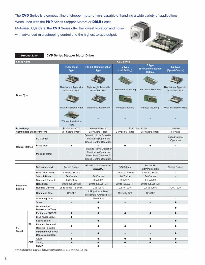
CVD Series Stepper Motor DriverProduct Line
The CVD Series is a compact line of stepper motor drivers capable of handling a wide variety of applications.
When used with the PKP Series Stepper Motors or DRL Series
Motorized Cylinders, the CVD Series offer the lowest vibration and noise
with advanced microstepping control and the highest torque output.
2

Type Frame Size
Additional Function
Standard With Encoder
With Electromagnetic
Brake
With Adjusting
Knob
2-P
ha
se
Standard Type
(Basic Step Angle:
1.8°/step)
20 mm (0.79 in.) ● ● − −
28 mm (1.10 in.) ● ● ● −
35 mm (1.38 in.) ● ● ● −
42 mm (1.65 in.) ● ● ● −
50 mm (1.97 in.) ● ● − −
56.4 mm (2.22 in.) ● ● ● −
60 mm (2.36 in.)✽ ● − − −
85 mm (3.35 in.) ● − − −
High-Resolution Type
(Basic Step Angle:
0.9°/step)
42 mm (1.65 in.) ● ● ● −
56.4 mm (2.22 in.) ● ● ● −
Flat Type
(Basic Step Angle:
0.018 to 1.8°/step)
42 mm (1.65 in.) ● − − −
60 mm (2.36 in.) ● − − −
51 mm (2.00 in.) With Harmonic Gear −
61 mm (2.40 in.) With Harmonic Gear −
SH Geared Type
(Basic Step Angle:
0.05 to 0.5°/step)
28 mm (1.10 in.) ● − − −
42 mm (1.65 in.) ● ● − −
60 mm (2.36 in.) ● ● − −
90 mm (3.54 in.)✽ ● − − −
CS Geared Type
(Basic Step Angle:
0.09 to 0.36°/step)42 mm (1.65 in.) ● − − −
5-P
ha
se
Standard Type
(Basic Step Angle:
0.72°/step)
20 mm (0.79 in.)✽ ● ● − −
28 mm (1.10 in.) ● − − −
42 mm (1.65 in.) ● ● − −
56.4 mm (2.22 in.) ● ● − −
60 mm (2.36 in.) ● ● − −
85 mm (3.35 in.)✽ ● − − −
High-Resolution Type
(Basic Step Angle:
0.36°/step)
42 mm (1.65 in.) ● − − −
60 mm (2.36 in.) ● − − −
TS Geared Type
(Basic Step Angle:
0.024 to 0.2°/step)
42 mm (1.65 in.) ● − − −
60 mm (2.36 in.) ● − − −
DRL Series 20 mm (0.79 in.) ● − − ●
28 mm (1.10 in.) ● − − ●
42 mm (1.65 in.) ● − ● ●
60 mm (2.36 in.) ● − ● ●
✽Conventional PK Series. ●About Electromagnetic Brakes · The electromagnetic brake is a non-excitation operation type, so while it is useful for holding loads while stopped, it is not a mechanism intended to reliably hold loads. Do not use as a safety brake.Wait until the motor has stopped when using the electromagnetic brake to hold a load.
· The CVD Series does not have a function to control electromagnetic brakes. The system to control the electromagnetic brake must be prepared by the customer.
With Harmonic GearStandard
Standard
Standard With Encoder
Standard
Standard
Standard With Encoder
With EncoderStandard With Electromagnetic Brake
Standard With Electromagnetic Brake
With Adjusting Knob
PKP Series Stepper Motors and DRL Series Motorized CylindersProduct Line
Standard With Encoder With Electromagnetic Brake
3

CVD Driver
Lower Heat Generation
Increased Torque
Cross section schematic view of FET and printed circuit board
FET package
FET chip
Copper foil
Flow of heatThrough hole parallel connections
Thermographic driver heat distribution when operated under identical conditions
Thermographic driver heat distribution when operated under identical conditions
4 layer circuit board
Conventional product or custom-built driver
Actual printed circuit board pattern
Actual Size
52.5 mm (2.07 in.)
24.5 mm (0.96 in.)
85 mm (3.35 in.)
The CVD Series drivers developed exclusively for the PKP Series stepper motors enables increased performance
and functionality.
Features of the CVD Series
Industry's Top, Compact, High Performance Driver
Select Drivers by Mounting Method
High-Effi ciency Design
These compact and lightweight drivers contribute to saving space. The 2-phase and 5-phase drivers are identical in size, installation and I/O connectors. This allows for the selection and evaluation of 2-phase or 5-phase drivers based on the required specifications.
● A 2-phase driver and 5-phase driver cannot be used together.Different phases require dedicated drivers .
Drivers with different shapes and connector locations are available to match the mounting method.
The CVD Series provides increased torque by increasing the output current compared to conventional products.In order to allow the increase of output current, the design incorporates measures to reduce the amount of heat generated.
● Available for both 2-phase and 5-phase.
Mass 20 g (0.71 oz) to 70 g (2.47 oz)(Differs according to the driver type.)
• Adoption of low-loss FET
• Pattern design that accounts of heat dissipation to the circuit board
• Adoption of FET with good heat dissipation properties
Board-Mount S Type
This is a board-mount type driver. For details, please
contact your nearest Oriental Motor sales offi ce.
Right Angle Type with Installation Plate
The connector points outward.
With Installation Plate
The connector points upward.
4

Low Vibration with Full-Time Microstepping
For High Positioning Accuracy Use a 0.72°/0.36° Stepper Motor
There's a Wide Choice with 1.8° and 0.72°/0.36° Stepper Motors
Low vibration and noise reduction have been achieved across all speed ranges by significantly improving the vibration level with the use of a fully digital-controlled full-time microstep driver. The CVD 5 phase driver and motor has further improved vibration characteristic.
0.6
0.4
0.2
00 200 300100 600500400
1.0
0.8
General 1.8° stepper motor3200 P/R (0.1125˚/step)
Vibr
atio
n Co
mpo
nent
Vol
tage
Vp-
p [V
]
Speed [r/min]
0.6
0.4
0.2
00 200 300100 600500400
1.0
0.8
CVK246AK3200 P/R (0.1125˚/step)
Vibr
atio
n Co
mpo
nent
Vol
tage
Vp-
p [V
]
Speed [r/min]
0.6
0.4
0.2
00 200 300100 600500400
1.0
0.8
CVK546AK3200 P/R (0.1125˚/step)
Vibr
atio
n Co
mpo
nent
Vol
tage
Vp-
p [V
]
Speed [r/min]
CVD/PKP Vibration characteristics for 0.72°/0.36° stepper motors have been further improved.
●Vibration Suppression Control
Common vibration that occurs in the mid-speed range
has been suppressed. This enables more stable torque
characteristics.
●Reduced Step Vibration
The new smooth drive control
with higher current control
increases the basic step angle
to a maximum resolution of
2048. As a result, a reduction
in step vibration in the low-
speed range is achieved.
Vibration level has been signifi cantly improved in all speed ranges.
In general, stopping accuracy tends to be lower during microstep operation✽ than full step operation and this effect is more noticeable in a 1.8° motor. In this situation, using a CVD 5 phase driver and motor enables a higher positioning accuracy.
✽Max. resolution 125000 P/R
●Stopping Accuracy0.72° stepper motor standard type ±0.05° (±3 min)0.36° stepper motor high-resolution type ±0.034° (±2 min)
0.02
-0.02
0
-0.06
-0.04
-0.08
-0.10 18090 360270
0.1
0.06
0.08
0.04
Stop
Pos
ition
Acc
urac
y [ ˚
]
Rotation Angle [ ˚ ]
When full stepping 200 P/R (1.8˚/step)
0.02
-0.02
0
-0.06
-0.04
-0.08
-0.10 18090 360270
0.1
0.06
0.08
0.04
Stop
Pos
ition
Acc
urac
y [ ˚
]
Rotation Angle [ ˚ ]
When microstepping 1600 P/R (0.225˚/step)
0.02
-0.02
0
-0.06
-0.04
-0.08
-0.10 18090 360270
0.1
0.06
0.08
0.04
Stop
Pos
ition
Acc
urac
y [ ˚
]
Rotation Angle [ ˚ ]
When full stepping 500 P/R (0.72˚/step)
0.02
-0.02
0
-0.06
-0.04
-0.08
-0.10 18090 360270
0.1
0.06
0.08
0.04
Stop
Pos
ition
Acc
urac
y [ ˚
]
Rotation Angle [ ˚ ]
When microstepping 5000 P/R (0.072˚/step)
●For a General 1.8° Stepper Motor ●For a CVD driver, 0.72°/0.36° Stepper Motor
Microstepping reduces stopping accuracy.
Microstepping does not reduce
stopping accuracy.
CVD/PKP High positioning accuracy is now possible with 0.72°/0.36° stepper motors
1.8°
0.72°/0.36°
0.72°/0.36°
The size, installation and I/O connectors for the CVD drivers and 1.8° or 0.72°/0.36° motors are the same. Because of this, it is easy to evaluate and select the proper package for the requirement.
✽The driver for a 1.8° stepper motor and the driver for a 0.72°/0.36° stepper motor are not interchangeable. Each motor type has a dedicated driver.Use the Step Angle Setting Switch to set the proper resolution without changing your controller’s pulse output.
CVD
1.8° can be used for devices that require high torque at low speed.
Device AdvantagesImproved motion functionality and performance throughout.
Advantage of Selection
● Common platform design
● Optimum performance
characteristics
●Guaranteed performance
CVD Drivers
1.8°
CVD
0.72°/0.36° can be used for devices that require low vibration, high speed and high
positioning accuracy.
0.72°/0.36°
5

CVD Series: Sinusoidal
Conventional: Trapezoidal
Digital Current ControllerPosition Command
(Pulse Signal)
Current Feedback (AC)
Voltage Command
(AC)
Position Command - Electrical Angle
Command Conversion
Current Command
AC➝DC Conversion
AC➝DC Conversion
Current control using direct
current amount
Control Amount Output
Feedback Input
0 200 300100 600500400
Speed [r/min]
Vibr
atio
n Co
mpo
nent
Vol
tage
Vp-
p [V
]
1.0
0.8
0.6
0.4
0.2
0
PKP246D23A2CVD223FBR-K3200P/R (0.1125˚/step)
Conventional 2-Phase Stepper Motor3200P/R (0.1125˚/step)
Low Vibration Achieved by Full-Time Microstep Drive
The CVD Series is a fully digital control driver. Currents are controlled digitally and calculated by a high-performance CPU.The waveform of the current for each phase is changed from the conventional trapezoidal to sinusoidal, which allows for micro-step driving in all speed regions, and has reduced vibration even more.
Reduction in Step VibrationThe new smooth drive control with its increased current control resolution allows the basic step angle to be divided into a max. of 2048 microstep angles. This has greatly reduced the step vibration at low speeds.
Vibration Suppression ControlVibration in the medium speed regions, which generally occurs regardless of the number of phases and the drive system type, has been suppressed. This stabilizes the torque characteristics and allows the motor to operate at high speeds without mis-stepping.
■ Digital Current Controller Mechanism ■ Illustration of Motor Current Waveform
Different driver shapes and connection methods are available to meet a wide range of mounting locations.
With Installation PlateRight Angle
Select the Type that Best Suits the Mounting Method
Example
The connectors point out from the side of the board. Oriental Motor also provides DIN rail mounting hardware and circuit covers (for pulse input type) as peripheral equipment.Refer to the peripheral equipment page for details.
Driver is Mounted Vertically
52.5 mm
85 mm
6

With Installation Plate
Without Installation Plate
Horizontal MountingVertical mounting
Number of Phases
Product Name
List PriceI/O Setting SPI Communication Setting
Horizontal mounting
Vertical mounting
Horizontal mounting
Vertical mounting
2-Phase CVD2H-K CVD2V-K CVD2H-KS CVD2V-KS $130.00
5-Phase CVD5H-K CVD5V-K CVD5H-KS CVD5V-KS $140.00
Example
Example
Example
The connector points upward from the board.
The connector points upward from the board. This type has no installation plate.
This type can be implemented into custom-made printed circuit boards. Both vertical mount and horizontal mount types are available.
Driver is Mounted Horizontally
Driver is Mounted Horizontally on an Installation Plate
Driver Mounted to Printed Circuit Board
CVD Series S Type
52.5 mm
45 mm
28 mm
85 mm
65 mm
65 mm
7

1.0
0.6
0.8
0.4
0.2
00 1000500 20001500
PKP246D23B2CVD223FBR-K 2.3A/Phase
Torq
ue [N
·m]
Speed [r/min]
2-Phase focuses on high torque at low speeds.
0
0.2
0.4
0.8
0.6
1.2
1.0
200 400 600 800 10000
Torq
ue [N
·m]
Speed [r/min]
PKP264D14A-SG3.6CVD228BR-K 1.4A/Phase
PKP264D14A2CVD228BR-K 1.4A/Phase
Example
Example
Example
For applications that require rapid acceleration and deceleration, 2-phase stepper motors with high torque at low speeds are recommended.
For applications that require rapid acceleration and deceleration with large amounts of inertia, 2-phase stepper motors with geared motors are recommended
Increased Resolution (400 p/rev). The number of rotor teeth has doubled to 100 compared to 50 with the standard type. As a result, the basic step angle becomes 0.9˚/step, which is half that of the standard type.
More powerful 5-phase RK Series stepper motors (AC input type) are also available.
2-Phase Stepper MotorPKP Series
2-Phase Stepper MotorPKP Series
SH Geared Type
2-Phase DriverCVD Series
2-Phase DriverCVD Series
■ Comparison of Speed – Torque Characteristics
■ High torque at low speeds
A motor that Matches the Desired Specifi cations can be Selected from a Wide Range of Speed and Torque Variations
Inching Operation Over Short Distances
Inching Operation Over Short Distances with Large Amount of Inertia
Improved Stopping Accuracy 0.9°, High Resolution PKP Series
Rotor
Stator
Shaft
Rotor
Stator
Shaft
Standard Type (50 teeth) High-Resolution Type (100 teeth)
◇Comparison of Displacement Angles Due to Frictional Load (Reference values)
Frictional load 0.3 N·m (42.4 oz-in)
0
0.05
0.10
0.15
0.20
0.25
0.30
High-Resolution Type(PKP266MD28A2)
Standard Type(PKP266D28A2)
Disp
lace
men
t Ang
le [˚
]
Example: Frictional load is constantly applied with a ball screw mechanism to the motor due to the guide block and guide rail.
The stopping accuracy improves as the torque increases while minimizing the negative effect of the frictional load.
Comparison of Angle – Torque Characteristics
−1.5
−1.0
−0.5
0
0.5
1.0
1.5
-1.8 1.8Torq
ue
Angle [˚]
Frictional Load0.3 N·m
Displacement Angle of Standard Type
PKP266D28A2(Standard Type)
PKP266MD28A2(High-Resolution Type)
Max. Holding Torque
Displacement Angle of High-Resolution Type
8

Signal Name Function
Input Signals
CW+ (PLS+) Rotates the motor in the CW direction.(Operation command pulse signal when in 1-pulse input mode)CW− (PLS−)
CCW+ (DIR+) Rotates the motor in the CCW direction.(Rotation direction signal when in 1-pulse input mode) CCW− (DIR−)
AWO+ Stops motor excitation.
AWO−
CS+Switches the step angle.
CS−
Output Signals
ALM+Outputs the alarm status for the driver (normally closed).
ALM−
TIM+ Output when the excitation state of the motor is step "0".
TIM−
I/O Signals
Stepper Motor Driver
This driver meets the need for easy synchronized operation with pulse input type drivers.
CVD Series Pulse Input Type
Names and Functions of Driver Parts
For details of motor and driver combinations, refer to
individual catalogs or the Oriental Motor website.
PLC/Pulse Generator
Step Angle Setting Switch
Running Current Setting Switch
Function Setting Switch
POWER LED andAlarm LED Display (Protective Functions)
Connection to Oriental MotorPKP Series Stepper Motor
24 VDC Power Supply
Max. Resolution 125000 P/R
16 Level Digital Setting
Sets the command fi lter, resolution
and smooth drive function.
I/O Connection
Stepper Motors
PKP Series2020/2021
9

Compatible with the Modbus (RTU) Protocol.
Stepper Motor Drivers
CVD Series RS-485 Communication Type
Movement with Modbus (RTU) control?
Simple data setting with touch screen?
These drivers meet those needs.
Switch BoxMotor Setting Switch
Termination Resistor Setting Switch
Support SoftwareMEXE02(Free download)
24 VDC Power Supply
Modbus (RTU)
● RS-485 communication, operation data and parameters can be set, and operation commands
can be input.
● The protocol is compatible with Modbus (RTU), allowing for easy control from a PLC, etc.
Max. 31 Axes ● Up to 31 axes can be connected to one host control device.
(Total extension distance: 10 m (32.8 ft) or less)
Pulse Generator Not Needed
● Operation data and parameters can be set, allowing for selected positioning operation.
(Operation data settings: 256)
● RS-485 communication also supports direct data operations for writing position and speed data.
Sets the applicable motor.
The driver that is farthest from the
host controller sets the termination
resistor.
Names and Functions of Driver Parts
Oriental MotorStepper MotorConnection with PKP Series
USB Connection
RS-485 Communication
Modbus (RTU)Touch Screen(Panel computer)
I/O Connection
10

The program can be simplifi ed with easy sequence functions
Settings can be copied and backed up
Movement from PC Movement from Touch Screen Movement by Switching a Switch
End effect is also controlled from the touch screen
along the X, Y, and Z axes
Easy control, just by switching a switch
Switch BoxPC Touch Screen
Control the motor with RS-485 communication
from a PC with imaging software
Comes with a monitoring function that contributes to visualization.
See the operating manual for details.
Series Name CVD Series
Type RS-485 Communication
Monitoring
Position ○✽
Speed ○✽
Driver temperature ○
Travel distanceCumulative travel distance
○
InformationDriver overheat ○
Travel distanceCumulative travel distance
○
Alarm Driver overheat ○
✽ Only command values can be monitored
Support Software MEXE02
Easy to understand, easy to use Intuitive operability
Teaching is also possible from a computer
Comes with a waveform monitor to check signal input conditions
Basic settings, such as operation data editing and parameter settings, can be easily made from a computer.
Sequence control is also possible, making simple system confi guration possible without a host sequence.
The support software can be downloaded from the Oriental Motor website.
Popular for being easy to handle, even if you’re not
an electrical designer!
Movement Examples
Simple Editing and Setting of Operation Data and Parameters
Contributes to Visualization
Check individual catalogs and the website
for details about motor and driver combinations.
Stepper Motors
PKP Series2020/2021
11

Time
Up to 256 points of data can be set
Spee
d
START Input
MOVE Output
FW-JOG Input
RV-JOG Input
Time
Spee
d
RVS Direction
FWD Direction Performs a deceleration stop when input is turned OFF
Starts JOG operation when input is turned ON
Operating Data
Time
Position
Position
Spee
d
AREA0 Output
AREA1 Output
No. 0 No. 1
AREA+Direction Position AREA−Direction Position
AREA+Direction PositionAREA−Direction Position
Time
Operating Data
Spee
d
START Input
MOVE Output
SEQ-BSY Output
No. 1No. 0
Time
Spee
d
FW-POS Input
M0 Input
Starts continuous operation when input is
turned ON
Performs a deceleration stop when input is
turned OFF
The speed changes if the operation data No. changes during
continuous operation.
Operating Pattern
Output Signals
The RS-485 communication type can set operation data in the driver, allowing for operation data to be selected and executed from a host.Operation data can also be linked.
■ Positioning SD operation
■ JOG
operation
■ AREA
output
■ Automatic
sequential
operation
■ Continuous
operation
Performs trapezoidal drive from the present position to the target position by setting the motor's operating speed, position (travel amount), etc. in the operation data.
Continuously operates the motor while the input signal is ON. Performs a deceleration stop when the input signal is turned OFF.
AREA output turns ON when the motor’s position is within the area range set for each operation data. Check “AREA range setting mode” in the operating manual for setting details.
Automatically executes two or more operations sequentially. Once one operation ends, it stops for the “drive-complete delay time”, after which operation of the operation data set in the “next data number” commences. If operation data with “no link” set is generated partway through, positioning SD operation is performed up to that operation data, then the motor stops.
Continuously operates the motor while the input signal is ON. The speed changes if the operation data number changes during continuous operation. The motor performs a deceleration stop when the input signal is turned OFF.
Pulse Generator not Needed
12

The main I/O signals of the RS-485 communication type are described here. See the operating manual for details about all I/O signals.
Signal Name Function
Input Signals
AWO Interrupts the motor current and places it into a non-excitation state. (Non-excitation when ON)
STOP Stop the motor.
ALM-RST Resets the alarm.
P-PRESET Executes the position preset.
FW-BLK Stops operation in the FWD direction.
RV-BLK Stops operation in the RVS direction.
FW-LS Inputs a limit sensor in the FWD direction (external sensor).
RV-LS Inputs a limit sensor in the RVS direction (external sensor).
HOMES Inputs a mechanical home sensor (external sensor).
SLIT Inputs a slit sensor in the RVS direction (external sensor).
START Executes a positioning SD operation.
SSTART Executes a positioning SD operation. Executes the next data number operation during manual sequential operation.
HOME Execute the return-to-home operation.
FW-JOG Executes a JOG operation in the FWD direction.
RV-JOG Executes a JOG operation in the RVS direction.
FW-POS Executes a continuous operation in the FWD direction.
RV-POS Executes a continuous operation in the RVS direction.
M0~M7 Uses 8 bits to select the operation data No.
R0~R7 General purpose signals.
Output Signals
CONST-OFF Output function is not used.
ALM-A Outputs the driver alarm status (normally open).
ALM-B Outputs the driver alarm status (normally closed).
READY Output when driver operation preparations are complete.
MOVE Output when the motor is operating.
VA Output when the operating speed reaches the target speed. (Command speed reference)
CRNT Output when the motor is excited.
AUTO-CD Output when in an auto current cutback state.
HOME-END Output when a return-to-home operation fi nishes and the position preset is executed.
ABSPEN Output when the coordinates are fi xed.
PLS-OUT 50 pulses are output for every rotation of the motor output shaft.
FW-SLS Output when the FWD direction software limit is reached.
RV-SLS Output when the RVS direction software limit is reached.
TIM Output every time the motor output shaft rotates 7.2° from home.
AREA0 Output when the motor is in the area. (Command position reference)
AREA1 Output when the motor is in the area. (Command position reference)
SEQ-BSY Output when a positioning SD operation is performed.
DELAY-BSY Output when the driver is in a standby state (Drive-complete delay time, Dwell).
DCMD-RDY Output when direct data operation preparations are complete.
INFO-DRVTMP Output when the conditions set in “Driver temperature information” are satisfi ed.
INFO-OVOLT Output when the conditions set in “Overvoltage information” are satisfi ed.
INFO-UVOLT Output when the conditions set in “Undervoltage information” are satisfi ed.
INFO-START Output when an “Operation start failure” occurs.
INFO-PR-REQ Output when either the position present or the return-to-home operation preset is executed.
INFO-MSET-E Output when a “Motor setting error” occurs.
INFO-NET-E Output when an “RS-485 communication error” occurs.
INFO-FW-OT Output when a “Forward direction operation prohibited” occurs.
INFO-RV-OT Output when a “Reverse direction operation prohibited” occurs.
INFO-TRIP Output when the motor output shaft’s total amount of rotation (command position reference) satisfi es the conditions set in “TRIP information”.
INFO-ODOOutput when the motor output shaft’s cumulative amount of rotation (command position reference) satisfi es the conditions set in “ODO information”.
INFO-DSLMTD Output when “Operation startup restriction mode” occurs.
INFO-IOTEST Output when “I/O test mode” occurs.
INFO-CFG Output when “Confi guration required” occurs.
INFO-RBT Output when “Reboot required” occurs.
Many I/O Signals
13

Low Speed
High Speed
Names and Functions of Driver Parts
Regular feed operation Smooth low speed operation
Back-and-forth operation
Switch BoxI/O Connection
24 VDC Power Supply
Operation is possible whether forward/reverse input is ON or OFFTwo-speed switching operationTwo-speed switching operation is possible
Simple Speed Control
CVD Series SC Type
Stepper Motor Drivers
Easy control with speed control motor sensing.
Speed Setting Switch
Sets the operating speed.
Function Setting Switch
Operation is possible whether forward input is ON or OFF
The speed range is 0.02 r/min to 600 r/min
Check individual catalogs
and the website for details
about motor and driver
combinations.
Simple speed control with a stepper motor.
Suppression of stop position variation in constant speed motors.
These drivers meet those needs.
Oriental MotorStepper MotorConnection with PKP Series
Sets the operating speed, operating current, and acceleration/deceleration time.
This product continues to rotate at the setting speed while forward (reverse) input is ON, but instantly stops when the input is OFF. Various operations can be achieved from the PLC depending on the length of time the forward (reverse) input is ON.
Improved Speed Control Made Simple
Stepper Motors
CVK Series
SC Type
14

Length of motor case Frame size
59
131
42
4280
80
Set the operating current
Set the operating speed
(Unit: mm)
Speed 2
Speed 1
Forward input
Reverse input
Speed switching input
Speed 1
Speed 2
Forward input
Reverse input
Speed switching input
Stall alarmMotor
Target stop position
Speed
Forward Input
Operation input OFF
Travel amount until stopping
Not necessary
Pulse Generator
24 VDC Power Supply
■ Two-speed switching operation■ Back-and-forth operation
■ Setting Item
■ When the alarm is stopped with a belt conveyor ■ Travel amount from the time the operation input is turned OFF until stopping
Using Constant Speed Motors and Inverters
Improved Stop Position Reproducibility
Pulse Generator Not Needed
Using Stepper Motors
Just turn the switch ON/OFF
Three types✽ of operation settings.
Easy Settings Also Reduces the Motor Space
Induction motor
CVD Series SC Type
Back-and-Forth Operation Achieved with Only Three Input Signals Two Speeds can be Set The Position is Also Held When Stopped
Contributes to Cost Reduction, Simple Control, and Improved Stopping Accuracy in Speed Control
Just adjust the setting dial
Motor Driver
Because stepper motors supply current to the motor even when stopped, the position can be held.
The speed can even be switched during driving.
The operating speed and rotation direction can be switched externally.
These motors are the answer to demands like keeping costs down with simple operations, and having a position holding function while stopped.
Direct data can be set in the driver, so control is possible without a pulse generator.
Set the acceleration/deceleration time
✽Settings are not needed if the initial setting values are used
Because the travel amount is constant from the time the operation input is turned OFF until stopping, stop position reproducibility is improved.This allows the time needed to adjust the stall alarm's position to be reduced.
● Operating speed (0.02 r/min∼600 r/min)
● Acceleration/deceleration time (0.00 s∼3.00 s)
● Operating current (100% or 70%)
Direct settings with a driver switchSwitch or
programmable controller
● Difficult to adjust the position of the alarm to get close to the intended stop position
● Variation in stop position due to weight of load
Accurate deceleration at the set deceleration rate
Stop without any variation due to the load
Output 25 W, Gear ratio 3Mass: 2.45 kgTorque: 0.39 N·m
PKP546N18A2Mass: 0.49 kgTorque: 0.5 N·m
Motor downsizing is achieved with the same rotation speed and torque as an induction motor.
Using a Stepper motor vs other motor types can improve stop position variation and sensor stopping accuracy.
15

Contributes to more Compact Equipment
Flat Type, for Limited Space
Smaller
Use a PKP Series motor in place of a standard motor from the PK Series with the equivalent torque in order to downsize motors.
Torque Characteristics Comparison of PKP244D15A2 and PK264-01A
0
0.1
0.2
0.3
0.4
0.5
0.6
0 500 1000 1500 2000
0 1 2 3 4 5
0
20
40
60
80PKP244D15A2PK264-01A
1.8˚/stepPulse Speed [kHz]
Speed [r/min]
Torq
ue [o
z-in
]
Torq
ue [N
·m]
39(1.54 in.)
□56.4(2.22 in.)
39(1.54 in.)
□42(1.65 in.)
PK264-01A PKP244D15A2
Provides torque equivalent to the next larger frame size!
This is Oriental Motor's flattest type of 2-phase stepper motors.
●Flat and Lightweight DesignThe motor can be installed in a narrow space.
Maximum Holding Torque: 0.18 N·m(25.5 oz-in)
Mass: 0.2 kg (0.44 lbs)
16 mm(0.63 in.)
□60 mm(2.36 in.)
Maximum Holding Torque: 0.1 N·m(14.2 oz-in)
Mass: 0.11 kg (0.24 lbs)
17 mm(0.67 in.)
□42 mm(1.65 in.)
●With Harmonic Gears ◇Attach the load to the surface of the flange to fix the load.
Example: Frame size 51 mm (2.01 in.)
Gear ratio 100Max. holding torque: 2.4 N·m (339 oz-in)Mass: 0.32 kg (11.3 oz)
◇Capable of Large Inertial Driving.Example: Frame size 51 mm (2.01 in.)
Inertia 0.12 kg·m2 (2.84 lb-ft2)(Approximately 7 times the rotor inertia)Inertial load: Diameter 0.35 m (13.8 in.),
Thickness 0.01 m (0.39 in.)Mass 7.6 kg (268 oz), Material iron
Motor: Length 17 mm (0.67 in.)Gear ratio 100
● is a registered trademark of Harmonic Drive Systems Inc.
Stepper Motor
PKP SeriesA wide variety of products is available for selecting the
optimal motor that needs your design specifications.
The PKP Series is smaller, has higher torque, and has improved basic performance over the conventional model.The product line can be incorporated into equipment with a variety of restrictions, such as the “Flat type” for extremely short motors, and the “High-resolution type” for motors resistant to frictional load.
The PKP Series is smaller, has higher torque, and has improved basic performance over the conventional model.The product line can be incorporated into equipment with a variety of restrictions, such as the “Flat type” for extremely short motors, and the “High-resolution type” for motors resistant to frictional load.
Standard Type
Geared Type With Encoder With Electromagnetic Brake
High-Resolution Type Flat Type
16

More Torque for Increased Performance
PKP Motors with Encoders or Brakes for more Application Support
Increase Torque Over the Entire Speed Range, from Low to High
After revising the magnetic and structure design of the PKP Series, it produces much more torque than the standard PK Series motors of the same size. In addition, torque can be increased in the high-speed range by using high current motors.
Comparison of Speed – Torque Characteristics of the Same Size Motors
0.1 1 10 100
0 30 300 3000
0
0.1
0.2
0.3
0.4
0.5
0.6
1.8˚/step
0.7
0.8
Torq
ue [N
·m]
Torq
ue [o
z-in
]
0
100
80
60
40
20
Speed [r/min]
Pulse Speed [kHz]
Constant Current Driver Power Supply Voltage: 24 VDCWith Clean Damper: JL=34×10−7 kg·m2 (Only for PK245DB)
PKP245D23B2(Current: 2.3 A/Phase)
PK245DB (Current: 1.5 A/Phase)
Comparison of Maximum Holding Torque
0
0.4
0.5
0.6
0.7
0.8
0.3
0.2
0.1
243 Type 264 Type
PK Series Standard Type PKP Series
0.2(28)
0.48(68)0.35
(49)
0.74(105)
Max
. Hol
ding
Tor
que
[ N·m
]
Max
. Hol
ding
Tor
que
[oz-
in]
0
100
80
60
40
20
High current is possible due to the revised motor winding design and the highly efficient design of the drive circuit that can be combined. Increased torque over the entire speed range from low to high is achieved.
●With Encoder(Provided for standard type, high-resolution type, and SH Geared Type)
●Main Specifications
Type Standard Type High-Resolution Type, SH Geared TypeResolution 200 P/R, 400 P/R 400 P/ROutput Signals
A phase, B phase, Z phase (3ch)
◇Motor Position Detection is PossibleMonitoring the current position and detecting positional errors is possible. For example, comparing the command position and current position enables you to check the normal operation of the motor.
Detection Pulse
Status
000000000000Normal
Abnormal
Command Pulse
Detection Pulse
Command Pulse
Example of System Configuration
2-Phase PKP Series with Encoder
Controller with Pulse Generator, etc.
Driver
◇Equipped with a Compact Encoder ●When frame size is 56.4 mm (2.22 in.)
Encoder
Unit = mm (in.)
16.5(0.65 in.)
20 m
ax.
(0.7
9 in
.)
◇High Reliability with Line Driver Output Circuit TypeNoise resistance is improved by differential output, and the wiring distance can be longer than with the voltage output type.
●The cables, which are convenient for wiring with an encoder, are available, sold separately.
●With Electromagnetic Brake(Provided for standard type and high-resolution type)
◇Position Can Be Held When the Power Is OFF or a Power Failure Occurs
This type features an electromagnetic brake that activates when the power is off.When the power is accidentally cut off due to a power failure or other unexpected event, the electromagnetic brake holds the load in position to prevent it from dropping or moving. Also, the load can be held by the electromagnetic brake when the motor is stopped, and the heat generated by the motor can be curtailed by switching the motor current off.
17

Geared Type
●CS Geared typeThe CS geared type has increased torque and a large shaft for greater loads without the requirement for a larger gear frame size.
◇Permissible TorqueProduct Name: PKP243 Rated Current: 2.3 A for Gear Ratio 10
0
0.2
0.4
0.6
0.8
1.0
1.2
0 50 100 150 200 250 300 350
Torq
ue [N
·m]
Speed [r/min]
CS Geared Type
SH Geared Type
Approximately 2 times the SH Geared Type
●Neugart Planetary PLE Geared TypeWhen more torque is required, consider the PKP Series with PLE Gearheads.
Visit the Oriental Motor website for more information.
◇Permissible Radial Load and Permissible Axial Load
Shaft Diameter: ϕ8 mm
80N (17.9 lbs)✽
40N(8.9 lbs)
Permissible Axial Load
Permissible Radial Load
✽When Distance from Shaft End is 10 mm (0.39 in.)
2.6 timesthe SH Geared Type
4 timesthe SH Geared Type✽
●As shown in the structural drawing, by losing gears, the output shaft can be placed at the central axis.
Gearhead Internal Structure Diagram
PlanetaryGearheads
High-Torque 2-Phase Stepper Motors
PKP Serieswith PLE Gearhead
High-Torque Combination Bipolar 2-phase Stepper Motorswith Neugart Planetary Gearheads
Short Delivery Time
●SH Geared TypeThis type is well-suited for deceleration, increased torque, high resolution, and limited vibration.It experiences less backlash than conventional products.
◇The Increased Speed Range Compared to Conventional Products
PK243A1-SG10 PKP243D15A2-SG10
2000
0.2
0.6
0
0.4
0.8
0.1
0.5
0.3
0.7
400100 300
0 108642 0.18˚/step
6
4
2
0
Pulse Speed [kHz]
Speed Range0 to 180 r/minTo
rque
[N·m
]
Speed [r/min]
Torq
ue [ l
b-in
]
0 100 200 300 400
0 108642 0.18˚/step
6
4
2
0
Pulse Speed [kHz]
Speed [r/min]
Torq
ue [N
·m]
Torq
ue [ l
b-in
]
Speed Range0 to 300 r/min
0
0.2
0.6
0.4
0.8
0.1
0.5
0.3
0.7
◇Increased Torque with the Same Motor Frame SizeWith the SH Geared Type, torque can be increased without changing the motor frame size.This is effective when motor installation space is limited and the frame size cannot be large.
42 mm(1.65 in.)
33 mm(1.3 in.)
59 mm(2.32 in.)
42 mm(1.65 in.)
42 mm(1.65 in.)
42 mm(1.65 in.)
Standard Type Motor Type SH Geared Type
PKP243D15A2 Product Name PKP243D15A2-SG18
0.35 N·m (49.5 oz-in) Max. Holding Torque 0.8 N·m (113.2 oz-in)
18

Motor connection cable
Power supply cable
RS-485 communication cable
RS-485 communication cable
I/O signal cable
Motor(Connector connection type)
Driver
Host controller
24 VDC power supply
Motor Connection Cable
I/O Signal Cable
DriverDC Power Supply Cable
Host Controller
24 VDC Power Supply
Motor(Connector Connection Type)
Peripheral
Equipment
Oriental Motor has a wide range of peripheral equipment to ensure that
you achieve the motion control system you want.
● 2-phase stepper motor PKP series and CVD series Example of pulse input type driver
● 2-phase stepper motor PKP series and CVD series Example of RS-485 communication type driver
Product Type Product Name List Price
Motor2-phase stepper motorConnector connection type
PKP264D28B2 $57.00
DriverWith mounting plateRight angle
CVD228BR-K $135.00
I/O Signal Cable Connector type Length 1 m CC12D010-2 $36.00
Motor Connection Cable Connection cable Length 1 m CCM010V2AEF $25.00
DC Power Supply Cable Connector type Length 1 m CC02D010-2 $20.00
Circuit Product CoverPulse input typeWith mounting plateRight angle
PADC-CVD $14.00
Mounting Brackets for Circuit Products
DIN rail mounting bracket MADP07 $11.00
Product Type Product Name List Price
Motor2-phase stepper motorConnector connection type
PKP264D28B2 $57.00
DriverWith mounting plateRight angle
CVD2BR-KR $190.00
RS-485 Communication CableFor connection to host controller Length 3 m
CC030-RS $23.00
RS-485 Communication CableFor connection between drivers Length 0.15 m
LH0015-RWN $10.00
Motor Connection Cable Connection cable Length 1 m CCM010V2AEF $25.00
Power Supply Cable/I/O Signal Cable Set
Connector type Length 1 m LHS010CC $14.00
Mounting Brackets for Circuit Products
DIN rail mounting bracket MADP07 $11.00
DIN Rail Mounting BracketCircuit Product Cover
For details, check the Oriental Motor website.
https://www.orientalmotor.com
✽The RS-485 communication type cannot be used.
Check individual catalogs and the website
for details about cables.
Stepper Motors
PKP Series2020/2021
19

Controller
Universal Controller
SCX11
The SCX11 Universal Controller is a highly functional and sophisticated controller, equipped with program editing and execution functions. The SCX11 is also able to control the motor via various serial ports such as USB, RS-232C and . Use the SCX11 to support Oriental Motor’s Pulse Input Type drivers.
■ Product Line
Product Name List Price
SCX11 $349.00
● Various Interfaces for Operation
RS-232C-Connector
-Connector
Top view
I/O
USB
●Direct Command Operation via CANopen ●Operations Using a PC or PLC
■ Features
● 100 Sequence Programs can be Stored ● Stored Program with GUI ● USB Connection to PC ● Various Interfaces for Operation ● External Encoder Input
● Stand Alone Operation Using Sensors and Switches
Start Switch
Lamp
Sensor 2Sensor 1
Motor
DriverGeneral Inputs
General OutputsBuzzer
Copyright ©2018 ORIENTAL MOTOR U.S.A. CORP.
ORIENTAL MOTOR U.S.A. CORP.Western Sales andCustomer Service CenterTel: (310) 715-3301 Fax: (310) 225-2594
Los AngelesTel: (310) 715-3301San JoseTel: (408) 392-9735
Midwest Sales andCustomer Service CenterTel: (847) 871-5900 Fax: (847) 472-2623
ChicagoTel: (847) 871-5900
DallasTel: (214) 432-3386TorontoTel: (905) 502-5333
Eastern Sales andCustomer Service CenterTel: (781) 848-2426 Fax: (781) 848-2617
BostonTel: (781) 848-2426CharlotteTel: (704) 766-1335
DetroitTel: (734) 808-0003
New YorkTel: (973) 359-1100
Technical Support
Tel: (800) 468-3982 / 8:30 A.M. to 5:00 P.M., P.S.T. (M–F) 7:30 A.M. to 5:00 P.M., C.S.T. (M–F)
E-mail: [email protected]
Obtain Specifications, Online Training
and Purchase Products at:
www.orientalmotor.com
Printed in USA 20U 0.5 12.22 #559
Specifications are subject to change without notice. This catalog was published in Jan, 2021.
This printed material uses ECF (Elemental Chlorine Free) paper and vegetable oil based inks.This combination is environmentally friendly.