step level procedure for remaining fatigue life …
TRANSCRIPT

ISSN 1822-427X print / ISSN 1822-4288 online
http://www.bjrbe.vgtu.lt
1. Introduction
Riveted construction are a very diffused type of historical metal railway bridges in Italy and around the world (Sus-tainable Bridges:2006 Guideline for Load and Resistance As-sessment of Existing European Railway Bridges – Advices on the Use of Advanced Methods. European Research Project under the EU 6th Framework Programme). These bridges were built during the second half of the 19th and the begin-ning of the 20th century, mainly using wrought iron and old steel. So, they have been capable of more than one centu-ry increasing loads and speeds, and they are consequently very close to their design fatigue life. Despite this, many of them are still in use today, appearing able to cope with current traffic demands. In order to understand and deep their safety, and to prevent the interruption of principle railroads lines due to localized failure or collapse, research on their structural performance and advanced fatigue as-sessment procedures are required. International rail au-thorities around the world are going to establish research initiatives in order to investigate the fatigue behaviour and the remaining service life of these bridges, and also in Ita-ly RFI (abbreviation in Italian – Rete Ferroviaria Italiana) has collaborated since 2005 with the University of Padua to deep this relevant phenomenon. The literature studies con-cerning the topic of riveted railway bridges, generally deep the matter by using different approach: using the fracture mechanics methods in order to predict crack sizes, in view of estimating information about the remaining fatigue life (Kühn et al. 2008); adopting finite element (FE) approaches
to investigate in depth the stress distributions in complex connections and rivets (Al-Emrani, Kliger 2003); exploit-ing FE analyses in order to perform 3D studies on statically indeterminate bridges (Brencich, Gambarotta 2009). Be-cause, materials, details, joints and structures are generally complex, all the aforementioned model-based studies need experimental validations. Conversely, the objective of this study was different: to investigate the classification method based on SN curves, in order to assess the shear category of EN 1993-1-9:2005 Eurocode 3. Design of Steel Structures. Fatigue for riveted shear splices of a metal historical bridge by proposing a step level assessment. The study starts with a general review of the matter and the description of the bridge assessed. Then the step level assessment is present-ed: in the first part material and full scale tests are high-lighted together with the suggestion of a new SN curve classification for riveted details; then current fatigue mod-el, compared to literature research results are explained; in the third part, load models and cycle counting methods are presented; finally, a deterministic and a simplified proba-bilistic assessment procedure are applied, and a full proba-bilistic procedure is presented. In this way, experimental findings highlighted in the first part of the paper are di-rectly applied in a step level assessment procedure with the advantage of using the classification method which is rela-tively simple and can be easily adopted by end users.
2. Fatigue failure in riveted connectionExperimental evidences of a consistent amount of riveted structures have shown that the great majority of fatigue
STEP LEVEL PROCEDURE FOR REMAINING FATIGUE LIFE EVALUATION OF ONE RAILWAY BRIDGE
Alessio PipinatoDept of Construction and Transportation, University of Padua,
Via Marzolo 9 – 35131 Padova, ItalyE-mail: [email protected]
Abstract. Reliable structural integrity and remaining life assessment are essential for infrastructural ageing mitigation of. For example, as a consequence of the lack of new riveted steel bridges, less attention has been paid in order to deep the topic of fatigue strength behavior and in particular less research has been focused on the topic of the remaining fatigue life of riveted structure. As a consequence, a series of diagnostic tests were performed on one short-span, two-lane, historical railway steel-girder bridge, in service from 1918. In this article are presented results concerning the step by step fatigue assessment of the bridge investigated: the safe condition of the bridge after almost a century service life period, apart from a dangerous failure mechanism have been evidenced, as confirmed by the analytical procedure and the experimental results reported.
Keywords: bridge, fatigue, assessment, steel, rivet, reliability.
doi: 10.3846/bjrbe.2010.04
THE BALTIC JOURNAL OF ROAD AND BRIDGE ENGINEERING
20105(1): 28–37

The Baltic Journal of Road and Bridge Engineering, 2010, 5(1): 28–37 29
failures are generally related to the connected material and not to the rivet itself (Kulak 2000); even if in case of missing rivets the possible collapse of a bridge is evidence that also rivets could play an important role in fatigue failure. Thus, the fatigue life should be affected and related to various factors, such as structural member and connection sizing, hole forming method, bearing condition, clamping force, material quality and corrosion state. The influences of these factors have not been describes in any systematic work, and the best data available are those investigating singular full scale bridge structure. No relevant attention has been paid concerning other bridge member deterioration factor in-fluencing also the fatigue life of this structural type, except for some detailed investigation (Kamaitis 2006).
Various analytical and numerical studies have also been carried out on riveted and bolted elements: some fi-nite element analyses were carried out mainly on bolted double-angle beam-to-column connections. Considerable research has also been carried out on modelling analyti-cally the moment-rotation behaviour and hence to obtain the rotational and translational stiffness of double-angle beam-to-column connections.
Key results are also reported in DiBattista et al. (1997), Bursi et al. (2002), Matar, Greiner (2006) and Pipinato et al. (2009a, 2009b): factors that have been found to play an important role in fatigue life, are for e.g. geometric imper-fections, such as the inclination and/or deflection of struc-tural elements, that could entail secondary stresses that are not usually taken into account in fatigue assessment; also vibrations, transverse horizontal forces, internal con-straints, localized and diffused defects such as corrosion damages, represent concurring causes of fatigue damage. In addition, the use of different riveting techniques either in-shop or on-site may entail different clamping force lev-els and variable load-carrying capacities both in members and in joints. The real evidence of the finite life of riveted metal bridges is represented by recent collapses: concen-tration of stresses in the bridge, due to addition of very heavy weight of construction equipment and material placed on the bridge itself combined with the already high stresses due to under-designed thicknesses could result in tragic and brittle progressive collapse, as reported in As-taneh-Asl (2008) concerning the I35-W bridge collapse in Minneapolis, USA (2007); long term differential vertical
settlement of bearings in hyperstatic structures could lead to concentration of stresses in fatigue damaged corroded members, and this has lead to the sudden collapse of the Piacenza Po bridge in Italy in 2009.
3. A recent experimental analysis
3.1. Bridge descriptionThe Meschio Bridge, was a short span riveted flanged rail-way bridge built in 1918, taken out of service in 2006. The bridge was in service in the line Mestre-Cormons locat-ed in the North-eastern part of Italy. The net span of the bridge was 12.40 m. The main horizontal structure was made by two couple of twinned riveted composite flanged beams. Wood beams recessed between the coupled beams with a clean distance of 550 mm from web to web made up the track. In this open-deck riveted type railway bridge, connections were typically double angles riveted in both the principle beams and floor-beam webs. The thickness of the main girder plates was 11 mm. Detailed design of the bridge are reported, and in particular the original design in Fig. 1, the geometrical survey in Fig. 2, and the cross sec-tion of the principle girders in Fig. 3.
3.2. Material investigationsThe physical and chemical as well as the mechani-
cal characterization of the base material of bridge compo-nents were carried out. In detail, they were employed to characterize the global structural behaviour and the resid-ual bridge life. Main test results are summarized here while detailed information can be found in Pipinato (2008) and Pipinato et al. (2008). The constituent material resulted to have mechanical strength almost equivalent to S275 steel according to EN 1993-1-1:2005 Eurocode 3: Design of Steel Structures – Part 1-1: General Rules and Rules for Buildings, with a mean yielding strength fy,m = 322 MPa and mean ul-timate strength fu,m = 421 MPa. About impact strength, the average CVN of 11.5 J results to be much lower than the reference value of 27 J suggested for modern steel in EN 10025-2:2004 European Structural Steel Standards. It was also performed a GDS, in which a Glow Discharge Atomic Emission Spectrometer was employed to perform quant metric and metallographic tests: the micrograph investi-gation showed a homogeneous grain distribution between
Fig. 1. Original project: a – side view; b – plan, Meschio Bridge, 1918 (Original design, courtesy of RFI)

30 A. Pipinato. Step Level Procedure for Remaining Fatigue Life Evaluation of One Railway Bridge
Fig. 2. Geometrical survey of the Meschio Bridge (Pipinato 2008)
0.013
0.0110.085
0.25
0.08
5
0.83
80.
011
0.013
0.0110.085
0.08
5
0.01
1 0.25
0.81
8 0.013
0.0110.085
0.08
5
0.01
1 0.25
0.79
8
Fig. 3. Geometrical survey of the Meschio Bridge, typical section of the principle beam corresponding to the A–A, B–B, C–C section reported in Fig. 2 (Pipinato 2008)

The Baltic Journal of Road and Bridge Engineering, 2010, 5(1): 28–37 31
ferrite and perlite with grain size of about 10–30 μm; these tests exhibited high sulphur and low carbon content. Vick-ers test results on rivets allow a material very close to Fe40 to be defined according Istruzione 44/f Verifica a fatica dei ponti ferroviari (Instruction 44/f:1992 Fatigue Verification of Railway Bridges).
3.3. Full scale tests
The most damaged details resulted to be the riveted short diaphragm connecting every 1 m the twinned beams, hav-ing been subjected to a large number of cycles compared to other details. For this reason, substructure tests focused on these hot-spot details. The principle tests performed were:
− three point bending tests, both monotonic or low cycle have been developed onto half a coupled girder, in order to characterize the static behav-iour of the structure; the monotonic test made on 1 not stiffened section, increasing the load from 0 to 2611 kN, have evidenced the out of plane of the web because of buckling; during the cyclic bending test, the beam has been loaded through the applica-tion of a vertical load concentrated at the midspan, increasing the load rate from 0 up to 3000 kN: once reached the max load rate a mid-span displacement of 2.4 mm was permanently discovered, confirming the plastic phase to have reached;
− monotonic test in simple shear on 1 single short diaphragm connection were also developed: the test was executed up to failure of the local riveted connection in the stiffener-to-web part; failure sud-denly occurred at a load level of about 1060 kN, ap-prox corresponding to a shear stress/force on single rivets of the 2nd and 3rd rows of 470 MPa;
− concerning the shear high cycle fatigue tests, short diaphragm riveted connections commonly em-ployed in old railway bridges were tested in cyclic shear to characterize the detail category. Test data confirm indeed the importance of that hot-spot de-tail for the estimation of the residual fatigue life of the whole bridge structure (Brühwiler et al. 1990). Four specimens were tested with different load ranges; in detail, specimen was loaded with 184 000 cycles up to failure, while specimens II, III and IV were tested up to 560 000, 208 850 and 504 515 cycles, respectively, all with a loading frequency of 5 Hz. No rivet failure and no fatigue cracking were observed in the connections of the bridge during its service life. Conversely micro cracks appeared in the central plates, in the angles and in the lateral web of each specimen induced by tensile stresses. The failure mechanism evidenced as a shear fail-ure of the rivet shank, is very dangerous, because it has occurred immediately and with no preliminary external evidence. Test results have been collect-ed in a logarithmic Wohler diagram illustrated in Fig. 4. Moreover the fatigue design curve according EN 1993-1-9: 2005 Eurocode 3: Design of Steel Struc-tures – Part 1-9: Fatigue, is compared with both ex-
perimental values and the corresponding Rm re-gression line. Though the EN 1993-1-9:2005 does not provide fatigue design curves as a function of this specific detail category, the curve of C = 100 has been adopted and provides results to be on the safe side; moreover a suggested category C = 110 is introduced. More detailed information on this ex-perimental studies could be found in Pipinato et al. (2009a) and in Pipinato et al. (2009b).
4. Fatigue assessment of railway bridges
As reported in Sustainable Bridges:2006, assessment could refer to the whole infrastructural line, to the single bridge, or to a specific detail. The step by step evaluation adopted in the research mentioned above (Pipinato 2008) and here partially reported, could be summed up by the following stages:
− study of design and inspection documents and their correctness;
− preliminary inspection in order to identify visually the structural system and possible damages;
− supplementary investigations in order to refine in-formation about the bridge;
− structural assessment in order to evaluate load car-rying capacity and safety of the bridge.
According to this scheme the fatigue assessment of the bridge analysed in this paper have been developed. In the following are presented the fatigue model discussion, the load model adopted, the cycle counting considerations, and finally the 3 steps of the assessment, the deterministic, the simplified probabilistic and some consideration on the possible full probabilistic approach.
4.1. Fatigue model
Full-scale bending fatigue tests of riveted members reported in the literature are the theoretical reference for SN curve
100
1000
1.00E+04 1.00E+05 1.00E+06 1.00E+07 1.00E+08Number of cycles
Experimental data
Suggested detail category
EC3_cat.100
Regression curveΔT = –53.6 ln(N) + 994.7
Suggested detailcategory
Stre
ss ra
nge,
MPa
Fig. 4. Test data, best fit, suggested category C = 110 and fatigue design curve category 100 according EN 1993-1-9:2005 (Pipinato 2008)

32 A. Pipinato. Step Level Procedure for Remaining Fatigue Life Evaluation of One Railway Bridge
design: they are shown in Figs 5, 6 together with the S-N curves of different fatigue detail categories of EN 1993-1-9 and of AREMA:2003 (American Railway Engineering and Maintenance of Way Association, Manual for Railway Engi-neering). A logarithmic regression curve fitting to obtain the mean life of the tests has also been represented. This com-parison and recent studies (Pipinato 2008) have evidenced that the most fitting and safe fatigue category for riveted details is C = 63 concerning the first code, while for ARE-MA:2003 is category D even though more data must be used in order to obtain a more detailed result; for comparison, similar analysis have been reported in Sustainable Bridg-es:2006, suggesting C = 71 for the same structural details. The hot-spot identified details resulted to be the mid-span lower flange detail 1, (Fig. 7a), and the short diaphragm con-nection detail 2 illustrated in Fig. 7b: these details have been assessed in the following. No relevant results as in bending are available for full scale shear tests of riveted members and for this reason this topic has not been reported.
The fatigue and damage assessment was performed by means of a semi-probabilistic approach through both
the Equivalent Stress Method and the Cumulative Damage Method as suggested by EN 1993-1-9. Moreover, in order to provide further estimates, the Sustainable Bridges:2006 models were employed. According to EN 1993-1-9, the fa-tigue check with the Equivalent Stress Method entails the use of the following ratio:
(1)
Riveted connection - AREA cat.71
10
100
1000
1.00E+04 1.00E+05 1.00E+06 1.00E+07 1.00E+08Numb er of cycles
Stre
ss ra
nge,
MPa
Akesson and Edlund (1996)Adamson and Kulak (1995)Baker and Kulak (1982) Mang and Bucak (1993)Akesson (1994)Fisher et al. (1987)Forsberg (1993)Abe (1989)Al-Ermani (2000)Rabemanantso and Hirt (1984)
Brühwiler et al. (1990)Out et al. 1984Reemsnyder (1975)Helmerich et al. (1997)Adamson DiBatista XiulinATLSSRmAREMA Cat. D (2003)
Fig. 6. Test data, best fit and fatigue design curve, category D, according AREMA:2003 (Pipinato 2008)
Fig. 7. Bridge details
Riveted connection - EC3 cat.90-71-63
10
100
1000
1.00E+04 1.00E+05 1.00E+06 1.00E+07 1.00E+08
Number of cycles
Stre
ss ra
nge,
MPa
Adamson and Kulak (1995)Baker and Kulak (1982)
Mang and Bucak (1993)
Akesson (1994)Fisher et al. (1987)
Forsberg (1993)
Abe (1989)
Al-Ermani (2000)
Rabemanantso and Hirt (1984)
Brühwiler et al. (1990)
Out et al. 1984
Reemsnyder (1975)
Helmerich et al. (1997)
Adamson
DiBatista Xiulin
ATLSS
Rm
EC3 cat.90 (2005)
EC3 cat.71 (2005)
EC3 cat.63 (2005)
Fig. 5. Test data and fatigue design curves, bending category detail C = 90, C = 71, C = 63 according EN 1993-1-9:2005 (Pipinato 2008)

The Baltic Journal of Road and Bridge Engineering, 2010, 5(1): 28–37 33
where – fatigue ratio for EN 1993-1-9 verification pro-cedure; – partial factor for equivalent constant ampli-tude stress ranges , MPa; – equivalent constant amplitude stress range related to 2 mln cycles, MPa; – reference value of the fatigue strength at NC = 2 mln cycles, MPa; – partial factor for fatigue strength .
Conversely, the cumulative damage approach implies the use of the Eq (2):
(2)
where – the number of cycles associated with the stress range for band i in the factored spectrum, MPa;
– the endurance (in cycles) obtained from the factored
vs. NR curve for a stress range of , MPa.
The corresponding rail traffic action adopted in these formulae was the load model 71 defined in EN 1991-2:2005 Eurocode 1: Actions on Structures – Part 2: Traffic Loads on Bridges.
With regard to the Sustainable Bridges:2006, the fa-tigue safety of all fatigue vulnerable details must be based on fatigue safety ratios. In detail, two ratios were consid-ered:
, (3)
where – fatigue ratio for Sustainable Bridges:2006 verification procedure; – fatigue limit of the investi-gated construction detail, MPa; – fatigue resistance co-efficient; – max fatigue action effect (stress range), MPa; – the fatigue strength, for which crack propa-gat:
, (4)
where – fatigue strength at 2 mln cycles (fatigue cat-egory), MPa; – (equivalent) fatigue load effect referred to 2 mln of cycles, MPa.
In this case, the relevant rail traffic actions considered and the load levels suggested are those of the Sustainable Bridges:2006 as depicted in Fig. 8 and Table 1.
4.3. Cycle counting
In order to perform a detailed damage assessment, an es-timation of cycles affecting each single detail was carried out: this estimate was performed by making tension/time fluctuations analyses for each detail and loading spectrum, as well as by counting the effective cycles as per ASTM E 1049-85:2005 Standard Practices for Cycle Counting in Fa-tigue Analysis.
4.4. Deterministic assessment
The use of Eqs (1) and (2) entails: a) lower flange – detail 1: = 0.4; Dd, EC3 = 0.1; b) short diaphragm connec-tion – detail 2: = 0.6; Dd, EC3 = 16 >> 1. Conversely, the use of Eqs (3) and (4) implies: c) lower flange – detail 1:
= 1.1; DED4.2 = 1.8; d) short diaphragm connection – detail 2: = 1.3; DED4.2 > 1.2.
These analytical estimates do clearly indicate that the cumulative damage approach highlight the fatigue vulner-ability of detail 2, i.e. of the short diaphragm connection. Nonetheless, experimental observations and inspections on the Meschio Bridge did not show evidence of crack initiation or propagation in that hot-spot detail. This ten-dency is clearly highlighted by Sustainable Bridges:2006, for which, the detail 2 is safe because load levels were as-sumed to grow up to 225 kN in the period from 1920 to 1980. So, the assumption appears to reflect the actual evo-lution of railway loadings. On the other hand, the constant load levels of 225 kN suggested by the load model 71 of EN 1991-2:2005 and considered for the whole life of the Meschio Bridge led to an overestimate of the fatigue life for both details.
4.5 Simplified probabilistic assessment
The probability of crack detection during inspection and monitoring is generally evaluated in an intermediate stage, and subsequently linked to the (calculated) probability of
Fig. 8. Equivalent Freight Train according Sustainable Bridges:2006: axle spacing and length
Table 1. Equivalent Freight Train according Sustainable Bridges:2006: axle loads and numbers of axles per wagon
Year < 1920 1921–1940 1941–1960 1961–1980 > 1980 MeanSpeed 50 70 80 100 120 100
Pk 160 180 200 200 225 200Pm 120 150 160 160 180 160A 2 3 4 4 4 4P0 40 40 50 50 50 50
Notes: Pk – characteristic value of the axle load, kN; Pm – mean value of the axle load, kN; A – number of axle per freight wagon; P0 – the axle load, kN, of an empty freight wagon

34 A. Pipinato. Step Level Procedure for Remaining Fatigue Life Evaluation of One Railway Bridge
fatigue fracture to obtain the probability of failure accord-ing Sustainable Bridges: 2006:
pfail = pfat (1 – pdet), (5)
where pfail – probability of failure; pfat – probability of fa-tigue fracture; pdet – probability of detection.
The probability of failure can also be expressed with the reliability index according to the standard normal dis-tribution. Finally the reliability of a structural element is compared to the target value:
βfail ≥ βtarget,
where βfail – reliability index with respect to failure; βtarget – target reliability index.
This model adopt the fatigue action effect (the re-quired nominal fatigue strength) as “required operational load factor αreq” which is obtained by dividing the required nominal fatigue strength by the action effect of the fatigue load, consisting of the load model UIC 71 (Kunz 1992):
, (6)
where αreq – required operational load factor; ΔσC,req – re-quired nominal fatigue strength, MPa; Δσ(ΦQfat) – stress range due to load model UIC 71 at worst position, MPa.
For a simplified probabilistic approach, a relation between mean value of required operational load factor
and number of future train passages Nfut – es-tablished by Kunz (1992) using the action effect of the traf-fic model in UIC 779-1:1986 Effect of the Slipstream of Pass-ing Trains on Structures Adjacent to the Track including assumptions on the scatter is adopted. The year 1990 was taken as the reference year from which on all future trains are counted (Nfut ≥ 1). The mean of required operational
load factor is then read for 3 different ranges of fatigue categories (expressed as ND, the cycle number of fatigue limit) starting from a predefined number of fu-ture trains Nfut (as from 1990). The relation is valid for in-fluence lengths over 10 m, a commissioning time 1900 ± 25 and a partition of freight traffic of 75%. There is one relation for 60 tpd (trains per day) and one for 120 tpd in the past (before 1990). According to the same model, a value of 0.04 may be taken as standard deviation (σ) of the required operational load factors, resulting from the assumed fuzziness of the traffic model. Adopting the fol-lowing notation and assumption:
sE = s(logαreq) = 0.04, (7)
(8)
where sE – the σ of the required fatigue strength; βfat(Nfut) – reliability index; mR = logΔσc + 2sR – the mean of the fa-tigue strength (log∆σ relating to N = 2 × 10⁶, MPa; mE(Nfut)
= m(logαreq) + logΔσ(ΦQfat) – the mean of the required fa-tigue strength as a function of the number of future trains
Nfut, number of cycles; – the σ of the fatigue
strength, MPa; m – the slope of the S-N curve; s(logN) – the σ of test results.
Concerning the choice on the target reliability index, it has been considered that for Serviceability Limit States specific values of β are recommended for a determinate re-maining service life, according ISO/CD 13822:1999 Basis for Design of Structures. Assessment of Existing Structures: for the fatigue limit state and a remaining service life of 50 years, a value of β = 2.3 is recommended in case of inspec-tion and β = 3.1 – if the element or detail is not inspection-able (ISO:1999). Therefore, indexes adopted here are the following: βmax = 3.1 – detail inspectable and βmin = 2.3 – detail not inspectable.
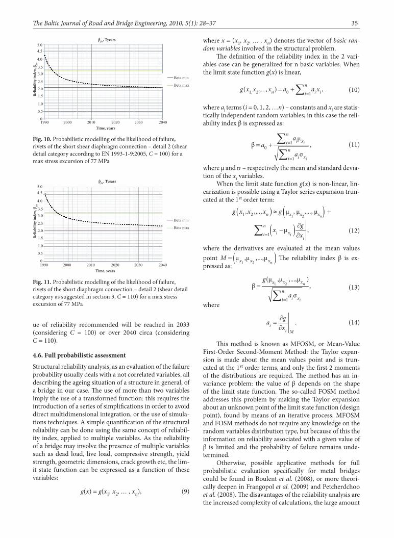
Graphs reported in the following pages, referred to an analysis with a medium annual passage of 50 000 trains (overestimating the period 1990–2006), a number of 60 tpd before 1990, and with the other fixed following param-eters: slope S-N curve m = 3; σ of test result, s(logN) = 0.45 (Kunz 1992); σ of the required fatigue strength, sE = 0.04. According to the experimental test previously reported in Part 3, a possible new category C = 110 also for shear has been introduced. Results are reported in Figs 9 and 10 with reference to detail category of EN 1993-1-9, and in Fig. 11 adopting the experimental detail category, for a max stress calculated excursion Dsφ = 72 MPa for the inferior flange at the midspan (detail 1) and Dtφ = 77 MPa for the most sollecitated riveted connection of the short shear diaphragm connection (detail 2).
Results are similar to the previous observation made on deterministic assessment: central rivets 2–3 have the worst reliability index. These results have been obtained, according to the experienced life of 89 years and of an average number of 50 000 tpy (trains per year) from 1990 to 2006 (137 tpd); in this way the remain-ing life of the entire bridge could be referred to lower value of the reliability index of the detail 2: the min val-
Beta minBeta max
1990 2000 2010 2020 2030 2040 2050 2060 2070 2080 2090 2100
4.5
5.0
4.03.5
3.0
2.5
2.0
1.5
1.0
0,5
0
βfat,Tyears
Time, years
Relia
bilit
y ind
ex, β
fat
Fig. 9. Probabilistic modelling of the likelihood of failure, inferior flange at the midspan – detail 1(bending detail category with reference to EN 1993-1-9:2005, C = 63) for a max stress excursion of 72 MPa
The Baltic Journal of Road and Bridge Engineering, 2010, 5(1): 28–37 35
ue of reliability recommended will be reached in 2033 (considering C = 100) or over 2040 circa (considering C = 110).
4.6. Full probabilistic assessment
Structural reliability analysis, as an evaluation of the failure probability usually deals with a not correlated variables, all describing the ageing situation of a structure in general, of a bridge in our case. The use of more than two variables imply the use of a transformed function: this requires the introduction of a series of simplifications in order to avoid direct multidimensional integration, or the use of simula-tions techniques. A simple quantification of the structural reliability can be done using the same concept of reliabil-ity index, applied to multiple variables. As the reliability of a bridge may involve the presence of multiple variables such as dead load, live load, compressive strength, yield strength, geometric dimensions, crack growth etc, the lim-it state function can be expressed as a function of these variables:
g(x) = g(x1, x2, … , xn), (9)
where x = (x1, x2, … , xn) denotes the vector of basic ran-dom variables involved in the structural problem.
The definition of the reliability index in the 2 vari-ables case can be generalized for n basic variables. When the limit state function g(x) is linear,
(10)
where ai terms (i = 0, 1, 2, …n) – constants and xi are statis-tically independent random variables; in this case the reli-ability index β is expressed as:
(11)
where μ and s – respectively the mean and standard devia-tion of the xi variables.
When the limit state function g(x) is non-linear, lin-earization is possible using a Taylor series expansion trun-cated at the 1st order term:
(12)
where the derivatives are evaluated at the mean values point The reliability index β is ex-pressed as:
(13)
where
(14)
This method is known as MFOSM, or Mean-Value First-Order Second-Moment Method: the Taylor expan-sion is made about the mean values point and is trun-cated at the 1st order terms, and only the first 2 moments of the distributions are required. The method has an in-variance problem: the value of β depends on the shape of the limit state function. The so-called FOSM method addresses this problem by making the Taylor expansion about an unknown point of the limit state function (design point), found by means of an iterative process. MFOSM and FOSM methods do not require any knowledge on the random variables distribution type, but because of this the information on reliability associated with a given value of β is limited and the probability of failure remains unde-termined.
Otherwise, possible applicative methods for full probabilistic evaluation specifically for metal bridges could be found in Boulent et al. (2008), or more theori-cally deepen in Frangopol et al. (2009) and Petcherdchoo et al. (2008). The disavantages of the reliability analysis are the increased complexity of calculations, the large amount
Beta min
Beta max
1990 2000 2010 2020 2030 2040
4.55.0
4.0
3.5
3.0
2.5
2.0
1.5
1.0
0.5
0
βfat, Tyears
Time, years
Relia
bilit
y ind
ex, β
fat
Fig. 10. Probabilistic modelling of the likelihood of failure, rivets of the short shear diaphragm connection – detail 2 (shear detail category according to EN 1993-1-9:2005, C = 100) for a max stress excursion of 77 MPa
Beta min
Beta max
1990 2000 2010 2020 2030 2040
4.55.0
4.0
3.5
3.0
2.5
2.0
1.5
1.0
0.5
0
βfat, Tyears
Time, years
Relia
bilit
y ind
ex, β
fat
Fig. 11. Probabilistic modelling of the likelihood of failure, rivets of the short diaphragm connection – detail 2 (shear detail category as suggested in section 3, C = 110) for a max stress excursion of 77 MPa

36 A. Pipinato. Step Level Procedure for Remaining Fatigue Life Evaluation of One Railway Bridge
of input data needed (which may be or not available) and the ability required to influence the results by manipulat-ing the input data. Fuzzy analysis could be also adopted, as for e.g. discussed in Kala (2007, 2008).
5. Conclusions
In order to study the fatigue behavior of metal riveted his-torical railway bridges, an investigation both experimen-tal and analytical/numerical was performed, focusing on the assessment of the remaining fatigue life of a case study. In this respect, results from experimental analysis of the 12.4 m span railway bridge near Sacile, Italy, taken out of service and transported to the laboratory and subjected to characterization tests on materials as well as high cycle fa-tigue tests on substructures have been described.
Code comparisons indicated that both EN 1993-1-9:2005 and AREMA:2003 codes are safe, even though no categorization of riveted details is considered by the Eu-ropean Code.
Moreover, the bending fatigue design curve provided by EN 1993-1-9:2005 best fits to experiment data with the category detail C = 63, while no comparison have been made for shear detail because the lack of literature data.
Concerning the testing results, a key aspect is that the experimental shear failure mode highlighted by high cycle fatigue testing is fragile and occurs without any external premonitory sign: this evidence should alert the compe-tent authorities.
Concerning the assessment performed, first a semi-probabilistic reliability assessment analysis was presented, by adopting the EN 1993-1-9:2005 and the Sustainable Bridges:2006 procedures. Both analyses confirmed that the most highly damaged hot-spot detail was the short dia-phragm riveted connection, while the Sustainable Bridg-es:2006 load model have predicted a minor and more realistic amount of cumulated damage for the identified hot-spot detail.
Then a simplified probabilistic assessment was per-formed assuming the Kunz method, comparing the detail category provided by EN 1993-1-9:2005, that coming from code and literature comparison and the correspondent suggested category found by testing: this have evidenced that the min value of reliability for the worst detail govern-ing the bridge life recommended by ISO/CD 13822:1999 (βmin = 2.3) will be reached in 2033 (considering a shear category detail C = 100) or over 2040 circa (considering a shear category detail C = 110, that comes from testing suggestions).
Therefore the experimental category C = 110 suggest-ed could be considered less safe, but more realistic, reveal-ing a longer remaining life for the structure.
6. Acknowledgements
This research would not have been possible without the generous support of RFI, Head Engineer Antonio Perrone (North Centre Italian Head of Investment, RFI) for the in-tense collaboration and the important occasion offered to test a real scale historical bridge. Many thanks also to FIP
Industriale SpA for the support concerning the full scale fatigue bending test. The opinions expressed are those of the author and do not necessarily represent those of the organizations involved in the project.
References Al-Emrani, M; Kliger, R. 2003. FE Analysis of Stringer-to-Floor-
Beam Connections in Riveted Railway Bridges, Journal of Constructional Steel Research 59(7): 803–818.
doi:10.1016/S0143-974X(02)00114-1Astaneh-Asl, A. 2008. Progressive Collapse of Steel Truss Bridg-
es, the Case of I-35W Collapse, Invited Keynote paper, in Proc of the 7th International Conference on Steel Bridges. June 4–6, 2008. Guimarăes, Portugal.
Boulent, M. I.; Righiniotis, T. D.; Chryssanthopoulos, M. K. 2008. Probabilistic Fatigue Evaluation of Riveted Railway Bridges, Journal of Bridge Engineering 13(3): 237–244.
doi:10.1061/(ASCE)1084-0702(2008)13:3(237)Brencich, A.; Gambarotta, L. 2009. Assessment Procedure and
Rehabilitation of Riveted Railway Girders: The Campasso Bridge, Engineering Structures 31(1): 224–239.
doi:10.1016/j.engstruct.2008.07.007Bursi, O. S.; Ferrario, F.; Fontanari, V. 2002. Non-Linear Analy-
sis of the Low-Cycle Fracture Behavior of Isolated Tee Stub Connections, Computers & Structures 80(27–30): 2333–2360.
doi:10.1016/S0045-7949(02)00252-3DiBattista, J. D.; Adamson, D. E.; Kulak, G. L. 1997. Fatigue
Strength of Riveted Connections, Journal of the Structural Engineering 124(7): 792–797.
doi:10.1061/(ASCE)0733-9445(1998)124:7(792)Frangopol, D. M.; Strauss, A.; Bergmeister, K. 2009. Lifetime Cost
Optimization of Structures by a Combined Condition-Reli-ability Approach, Engineering Structures 31(7): 1572–1580. doi:10.1016/j.engstruct.2009.02.036
Kala, Z. 2007. Influence of Partial Safety Factors on Design Reli-ability of Steel Structures – Probability and Fuzzy Probability Assessments, Journal of Civil Engineering and Management 13(4): 291–296.
Kala, Z. 2008. Fuzzy Probability Analysis of the Fatigue Re-sistance of Steel Structural Members under Bending, Jour-nal of Civil Engineering and Management 14(1): 67–72. doi:10.3846/1392-3730.2008.14.67-72
Kamaitis, Z. 2006. Deterioration of Bridge Deck Roadway Mem-bers. Part I: Site Investigations, The Baltic Journal of Road and Bridge Engineering 1(4): 177–184.
Kulak, G. L. 2000. Fatigue Strength of Riveted Shear Splices, Progress in Structural Engineering and Materials 2(1): 110–119. doi:10.1002/(SICI)1528-2716(200001/03)2:1<11 0::AID-
PSE13>3.0.CO;2-6Kunz, P.; Hirt, M. A. 1992. Reliability of Railway Bridges un-
der Fatigue Loading, in Proc of the 3rd International Work-shop on Bridge Rehabilitation “Bridge Rehabilitation”. Ed. by König, G..; Nowak, A. S. June 14–17, 1992, Darmstadt, Ger-many. Berlin: Ernst and Sohn, 515–528.
Kühn, B.; Luki, M.; Nussbaumer, A.; Günther, H.-P.; Helm-erich, R.; Herion, S.; Kolstein, M. H.; Walbridge, S.; And-roic, B.; Dijkstra, O.; Bucak, Ö. 2008. Assessment of Existing Steel Structures: Recommendations for Estimation of Re-maining Fatigue Life, Joint Report Prepared under the JRC_ECCS cooperation agreement for the evolution of Eurocode 3 (programme of CEN/TC 250). Ed by Sedlacek G.; Bijlaard, F.; Géradin, M.; Pinto, A.; Dimora, S. 1st edition. Background documents in support to the implementation, harmoniza-

The Baltic Journal of Road and Bridge Engineering, 2010, 5(1): 28–37 37
tion and further development of the Eurocodes. February 2008, EUR 23252 EN
Petcherdchoo, A.; Neves, L. A. C.; Frangopol, D. M. 2008. Op-timizing Lifetime Condition and Reliability of Deteriorating Structures with Emphasis on Bridges, Journal of Structural Engineering 134(4): 544–552.
doi:10.1061/(ASCE)0733-9445(2008)134:4(544)Pipinato, A. 2008. High Cycle Fatigue Behaviour of Historical
Metal Riveted Railway Bridges. PhD thesis 2008: University of Trento, University of Padua, in collaboration with RFI-Rete Ferroviaria Italiana and FIP Industriale, Publischer Univer-sity of Trento, Trento. 336 p.
Pipinato, A.; Pellegrino, C.; Modena, C. 2008. Evaluation and Fa-tigue Strength of One Riveted Historical Railway Bridge, in Proc of the 4th International Conference on Bridge Maintenance,
Safety and Management (IABMAS’08) “Bridge Maintenance, Safety Management, Health Monitoring and Informatics”. 1st edition. Ed. by Hyun-Moo Koh, H. M.; Frangopol, D. M. July 13–17, 2008, Seoul, Korea. London: Taylor and Francis. ISBN: 0415468442
Pipinato, A.; Molinari, M.; Pellegrino, C.; Bursi, O.; Modena, C. 2009a. Fatigue Tests on Riveted Steel Elements Taken from a Railway Bridge, Structure and Infrastructure Engineering 5(4).
doi:10.1080/15732470903099776Pipinato, A.; Pellegrino, C.; Bursi, O.; Modena, C. 2009b. High-
cycle Fatigue Behavior of Riveted Connections for Rail-way Metal Bridges, Journal of Constructional Steel Research 65(12): 2167–2175. doi:10.1016/j.jcsr.2009.06.019
Received 26 August 2008, accept 7 January 2010