step into full 3d modeling with gohfer 9 - barree 3d modeling with... · step into full 3d modeling...
TRANSCRIPT
Step Into Full 3D Modelingwith GOHFER 9.0
R. D. Barree
February 20, 2017
Barree & Associates
© 2017
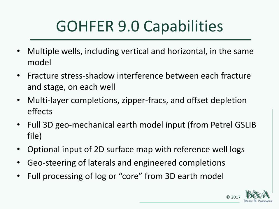
GOHFER 9.0 Capabilities
• Multiple wells, including vertical and horizontal, in the same model
• Fracture stress-shadow interference between each fracture and stage, on each well
• Multi-layer completions, zipper-fracs, and offset depletion effects
• Full 3D geo-mechanical earth model input (from Petrel GSLIB file)
• Optional input of 2D surface map with reference well logs
• Geo-steering of laterals and engineered completions
• Full processing of log or “core” from 3D earth model
© 2017
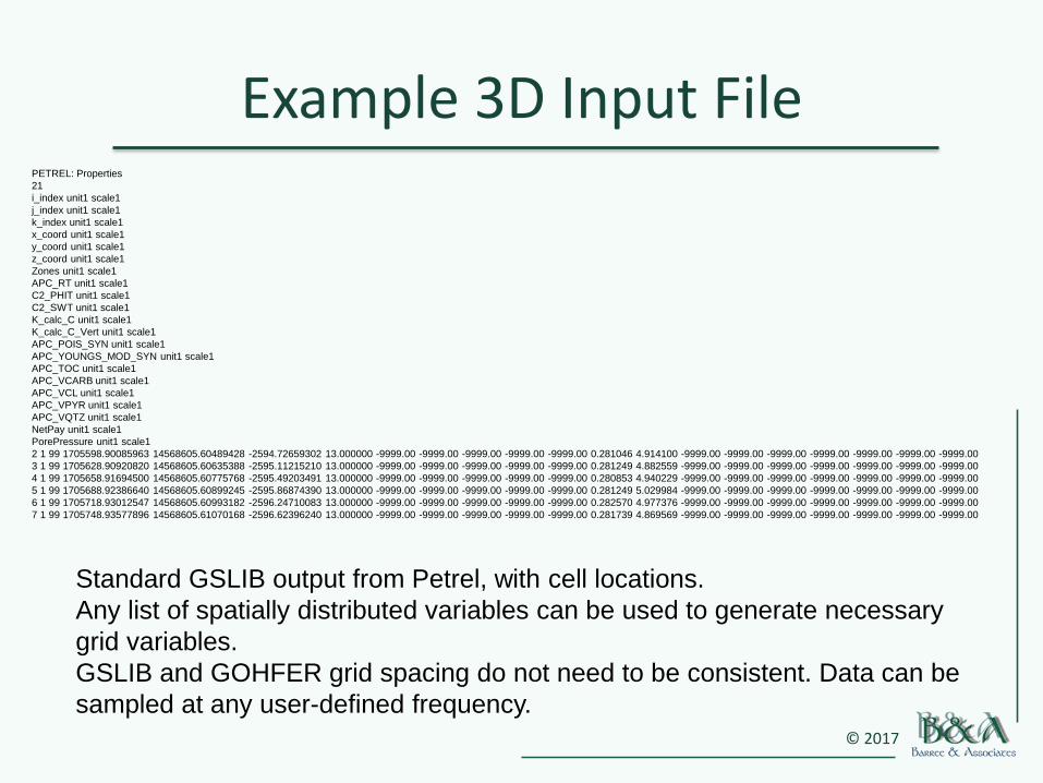
Example 3D Input FilePETREL: Properties
21
i_index unit1 scale1
j_index unit1 scale1
k_index unit1 scale1
x_coord unit1 scale1
y_coord unit1 scale1
z_coord unit1 scale1
Zones unit1 scale1
APC_RT unit1 scale1
C2_PHIT unit1 scale1
C2_SWT unit1 scale1
K_calc_C unit1 scale1
K_calc_C_Vert unit1 scale1
APC_POIS_SYN unit1 scale1
APC_YOUNGS_MOD_SYN unit1 scale1
APC_TOC unit1 scale1
APC_VCARB unit1 scale1
APC_VCL unit1 scale1
APC_VPYR unit1 scale1
APC_VQTZ unit1 scale1
NetPay unit1 scale1
PorePressure unit1 scale1
2 1 99 1705598.90085963 14568605.60489428 -2594.72659302 13.000000 -9999.00 -9999.00 -9999.00 -9999.00 -9999.00 0.281046 4.914100 -9999.00 -9999.00 -9999.00 -9999.00 -9999.00 -9999.00 -9999.00
3 1 99 1705628.90920820 14568605.60635388 -2595.11215210 13.000000 -9999.00 -9999.00 -9999.00 -9999.00 -9999.00 0.281249 4.882559 -9999.00 -9999.00 -9999.00 -9999.00 -9999.00 -9999.00 -9999.00
4 1 99 1705658.91694500 14568605.60775768 -2595.49203491 13.000000 -9999.00 -9999.00 -9999.00 -9999.00 -9999.00 0.280853 4.940229 -9999.00 -9999.00 -9999.00 -9999.00 -9999.00 -9999.00 -9999.00
5 1 99 1705688.92386640 14568605.60899245 -2595.86874390 13.000000 -9999.00 -9999.00 -9999.00 -9999.00 -9999.00 0.281249 5.029984 -9999.00 -9999.00 -9999.00 -9999.00 -9999.00 -9999.00 -9999.00
6 1 99 1705718.93012547 14568605.60993182 -2596.24710083 13.000000 -9999.00 -9999.00 -9999.00 -9999.00 -9999.00 0.282570 4.977376 -9999.00 -9999.00 -9999.00 -9999.00 -9999.00 -9999.00 -9999.00
7 1 99 1705748.93577896 14568605.61070168 -2596.62396240 13.000000 -9999.00 -9999.00 -9999.00 -9999.00 -9999.00 0.281739 4.869569 -9999.00 -9999.00 -9999.00 -9999.00 -9999.00 -9999.00 -9999.00
Standard GSLIB output from Petrel, with cell locations.
Any list of spatially distributed variables can be used to generate necessary
grid variables.
GSLIB and GOHFER grid spacing do not need to be consistent. Data can be
sampled at any user-defined frequency.
© 2017
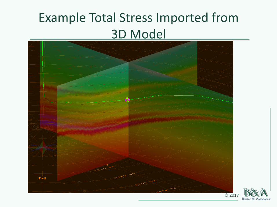
Example Total Stress Imported from 3D Model
© 2017
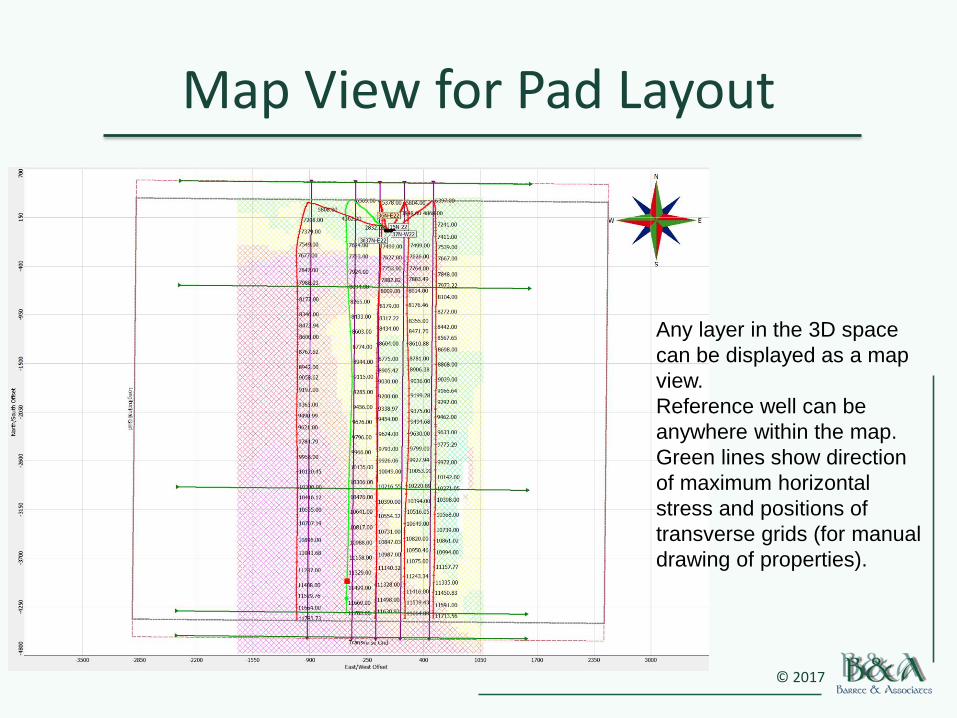
Map View for Pad Layout
Any layer in the 3D space
can be displayed as a map
view.
Reference well can be
anywhere within the map.
Green lines show direction
of maximum horizontal
stress and positions of
transverse grids (for manual
drawing of properties).
© 2017
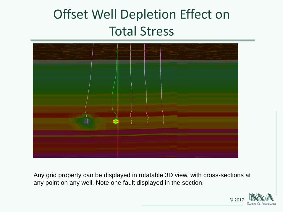
Offset Well Depletion Effect on Total Stress
Any grid property can be displayed in rotatable 3D view, with cross-sections at
any point on any well. Note one fault displayed in the section.
© 2017
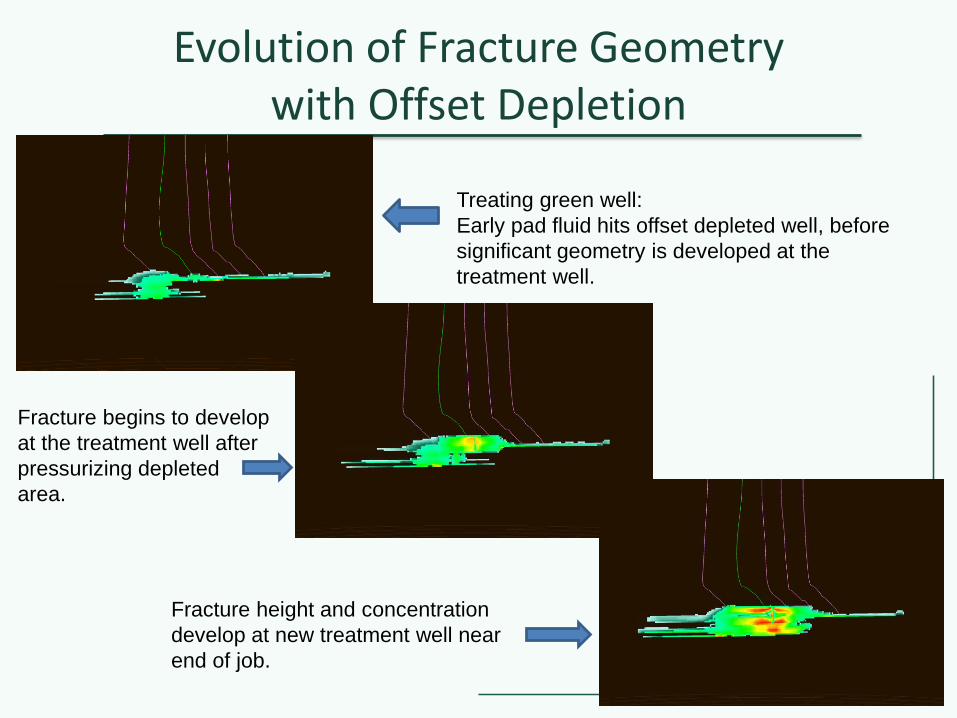
Evolution of Fracture Geometry with Offset Depletion
Treating green well:
Early pad fluid hits offset depleted well, before
significant geometry is developed at the
treatment well.
Fracture begins to develop
at the treatment well after
pressurizing depleted
area.
Fracture height and concentration
develop at new treatment well near
end of job.
© 2017
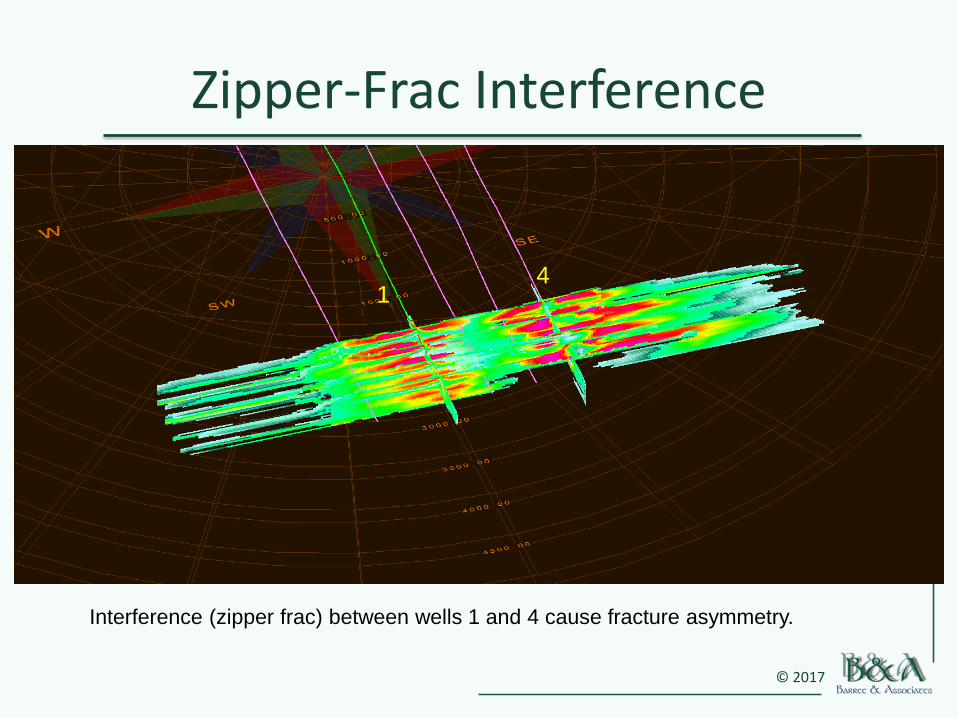
Zipper-Frac Interference
14
Interference (zipper frac) between wells 1 and 4 cause fracture asymmetry.
© 2017
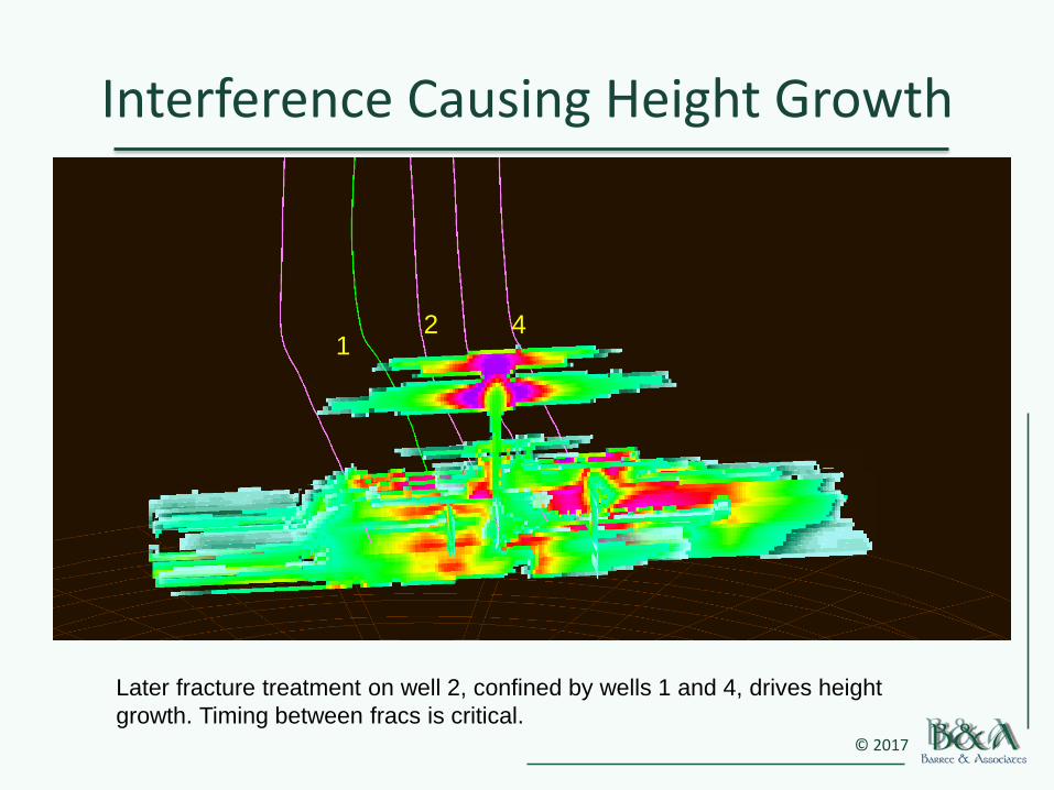
Interference Causing Height Growth
Later fracture treatment on well 2, confined by wells 1 and 4, drives height
growth. Timing between fracs is critical.
142
© 2017
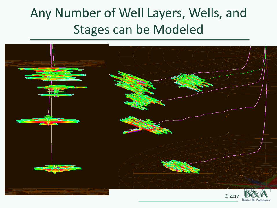
Any Number of Well Layers, Wells, and Stages can be Modeled
© 2017
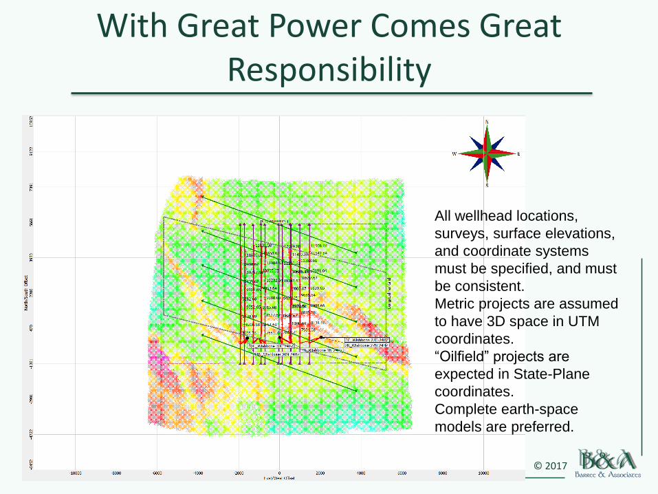
With Great Power Comes Great Responsibility
All wellhead locations,
surveys, surface elevations,
and coordinate systems
must be specified, and must
be consistent.
Metric projects are assumed
to have 3D space in UTM
coordinates.
“Oilfield” projects are
expected in State-Plane
coordinates.
Complete earth-space
models are preferred.
© 2017
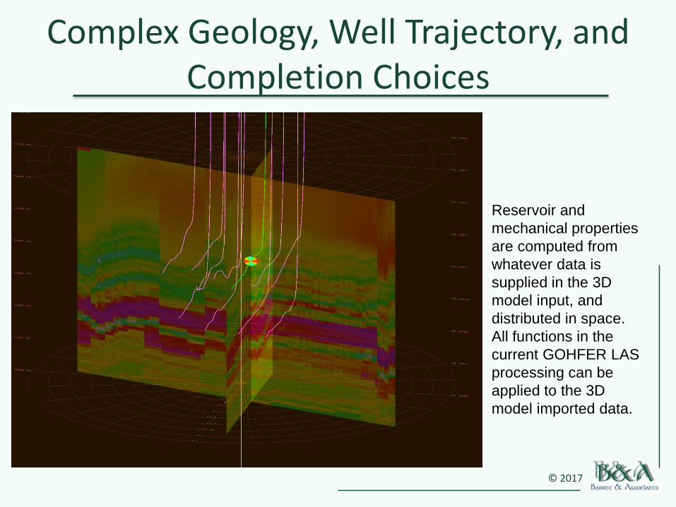
Complex Geology, Well Trajectory, and Completion Choices
Reservoir and
mechanical properties
are computed from
whatever data is
supplied in the 3D
model input, and
distributed in space.
All functions in the
current GOHFER LAS
processing can be
applied to the 3D
model imported data.
© 2017
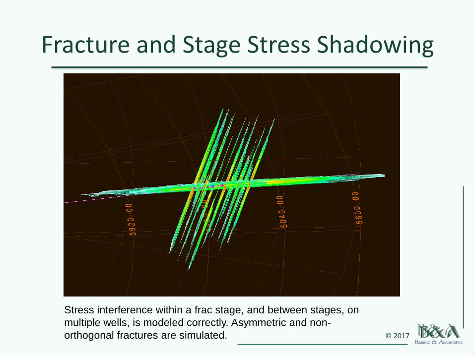
Fracture and Stage Stress Shadowing
Stress interference within a frac stage, and between stages, on
multiple wells, is modeled correctly. Asymmetric and non-
orthogonal fractures are simulated.
© 2017
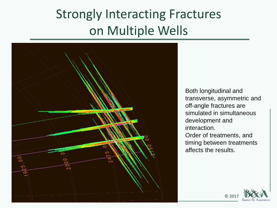
Strongly Interacting Fractures on Multiple Wells
Both longitudinal and
transverse, asymmetric and
off-angle fractures are
simulated in simultaneous
development and
interaction.
Order of treatments, and
timing between treatments
affects the results.
© 2017
Enter the Fourth Dimension• Timing of “zipper fracs” between wells or stages, allowing closure and
relaxation of induced pore pressure and strain, can be simulated
• Time-dependent evolution of pore pressure and coupled stress fields can be modeled
• Pore pressure depletion in offset wells significantly affects treatment of infill wells
• Effectiveness of “protection fracs” and injection into existing wells can be evaluated
• Direct import of 3D pore pressure distribution from reservoir simulators, into the model space, should be possible if coordinate systems overlap
• GOHFER supports output of fracture geometry and conductivity profiles for all fracture planes, on all wells, in CMG and Triplets file formats
• Micro-seismic event locations can be imported and displayed on 3D outputs, along with generated fracture geometries

© 2017
Get Yourself Out Of the Mangrove Swamp
Don’t be stuck with pseudo-anything in your
models.
Full 3D fracture geometry modeling with
GOHFER.
Simultaneous transverse and longitudinal
fractures, with full stress-interaction.
Complex fracture height growth resulting from
interference.
Full coupling with Petrel and numerical
reservoir simulators.
Industry leading proppant and fluid rheology
models and databases.
Complete production forecasting, economic
analysis, and production rate-transient and
decline analysis.
Computation of reservoir and mechanical
properties from logs or 3D model input.
Inclusion of micro-seismic results.