stenflex main catalog a07 deutsch - hanwel · pdf fileunalloyed steel tie rods – 5.6,...
TRANSCRIPT

PTFE compensatorsGeneral description of PTFE compensators
PTFE compensators have been de-veloped for certain applications.PTFE has a universal chemical resis-tance against almost all chemicalsand solvents within its continuous op-erating temperature – with the excep-tion of molten alkalis, elementary fluo-rine and certain halogenes.They are used primarily in appliances,machinery, apparatus and pipe-sys-tems■ to compensate for movement■ to compensate for expansion caused
by differences in temperature■ to reduce tension■ to dampen oscillation, hinder vi-
bration transmission, muffle noise/sound
■ as adapters to compensate for as-sembly or installation inaccuracies.
Purpose
31
For more than 40 years STENFLEXPTFE compensators have been manu-factured from top quality materials.They have served with distinctionthroughout decades of practical use.Constant further development and in-novations continuously update ourproduct range to meet the demandsof current and changing markets. Theresult: efficient and highly reliableproducts with superior durability.
Development/DesignSTENFLEX PTFE compensators arerated by calculation and optimized byexperimentation. Our developmentengineers use the most up-to-datedevelopment tools to validate the de-sign process in terms of form, func-tion and installation – from the earlieststage of the development process.This ensures that we can provide effi-cient, highly dependable productswith a long service life.
STENFLEX PTFE compensatorsvary with regard to the followingcriteria:■ type (universal and lateral com-
pensator)■ structure of the bellows (rated to
pressure and temperature load)■ flange connectionOur PTFE compensators are deliveredready for installation.In addition to our standard versionsfeatured in the catalogue, we also de-velop special versions that are pro-duced to operate under special condi-tions.Connecting parts (that deviate fromDIN), such as ISO, ANSI, BS, VG, SAE-standards etc. can also be supplied.
Versions
Universal PTFE compensatorsStructure:Bellows with connection parts (rotating flanges)
Movement absorption:The absorption of axial, lateral, angular and simultaneous movement is possi-ble. Universal compensators with two bellows and a connecting pipe are usedto absorb large movement.
Fixed points:Robust pipe fixed points and correct pipe-routing are essential when axial forcemust be absorbed.
axia
lla
tera
lan
gula
r
Lateral PTFE compensatorsStructure:Bellows with flanges and laterally moving restraints
Movement absorption:Lateral shift of the compensator is possible. The restraint absorbs axial reactionforce and relieves pressure on the pipe’s fixed points. Lateral compensatorswith two bellows and a connecting pipe are used to absorb large movement.
Fixed points:Only light fixed points are needed to absorb lateral moving and friction force.
late
ral
PTFE compensators are mainly usedin the following industries:■ Chemical industry■ Process engineering■ Food product industry■ Beverage industry■ Pharmaceutical industry■ Treatment and disposal technology■ Information Technology
Properties ApplicationsMaterial grade
PTFEPolytetrafluoroethyl-ene
Organic and inorganic acids,lyes, chloride, sulphate, solvents, bleaches, peroxide,fuels, mineral oil, hydraulic oil,halogens, gases
Heat-, and weather-proof material with outstanding chemicalresistance to aggressive media. Excellent electrical insulatingproperties*. Temperature resistance in continuous operationfrom –50 °C to +200 °C.
TeflonHostaflon
FluonPolyfluoron
Trade names
32
PTFE bellows
Material qualitiesSTENFLEX PTFE bellows are madefrom top quality material grades tocover a range of operating conditionsin many different areas.
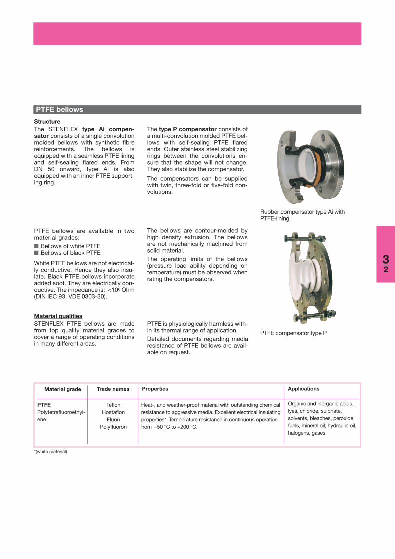
StructureThe STENFLEX type Ai compen-sator consists of a single convolutionmolded bellows with synthetic fibrereinforcements. The bellows isequipped with a seamless PTFE liningand self-sealing flared ends. From DN 50 onward, type Ai is alsoequipped with an inner PTFE support-ing ring.
The type P compensator consists ofa multi-convolution molded PTFE bel-lows with self-sealing PTFE flaredends. Outer stainless steel stabilizingrings between the convolutions en-sure that the shape will not change.They also stabilize the compensator.
The compensators can be suppliedwith twin, three-fold or five-fold con-volutions.
PTFE bellows are available in twomaterial grades:■ Bellows of white PTFE■ Bellows of black PTFE
White PTFE bellows are not electrical-ly conductive. Hence they also insu-late. Black PTFE bellows incorporateadded soot. They are electrically con-ductive. The impedance is: <106 Ohm(DIN IEC 93, VDE 0303-30).
The bellows are contour-molded byhigh density extrusion. The bellowsare not mechanically machined fromsolid material.The operating limits of the bellows(pressure load ability depending ontemperature) must be observed whenrating the compensators.
PTFE is physiologically harmless with-in its thermal range of application.Detailed documents regarding mediaresistance of PTFE bellows are avail-able on request.
Rubber compensator type Ai withPTFE-lining
PTFE compensator type P
*(white material)

33
Connection parts
The connections are standardized tofit commercially available pipes andflanges. See data sheets for details.
FlangesFlanges for PTFE compensators inthe Ai-series have a special turnedgroove to accommodate the rubberrim and are mounted in a rotating po-sition at the bellows. This makes itmuch easier to mount the pipeline.The flanges have stabilizing collars onthe side facing the bellows. This sta-bilizes the bellows and ensures com-pliance with safety spacing betweenthe ends of the screws and the rubberbellows throughout the entire pres-sure and movement range. This elimi-nates the risk of damage to the rubberbellows possibly caused by thescrewends.STENFLEX PTFE compensators inthe P-series have rotating flanges.
■ Flange with molded ears■ Oval flangesFlanges made of unalloyed steels areelectrogalvanized or given an anti-corrosion prime coating. Stainlesssteel is used to meet tougher corro-sion protection requirements. Othermaterials and forms of corrosion pro-tection (hot-dip galvanizing, specialvarnish, special coating etc.) areavailable on request.
pumps, tanks etc., by standardflanges.
STENFLEX PTFE compensators aresupplied ready for installation. Theyare connected to pipes, fittings,
STENFLEX lateral compensators withtie rod restraints, have been devel-oped for high operating pressures orlarge-diameter pipes. The axial forceproduced by pipeline inner pressure isabsorbed by the compensator re-straints. They relieve the pressure onthe fixed points of the pipeline.Flanges for lateral compensators areequipped with ears for tie rod re-straints. Depending on compensatortype and size, they differ as follows:
Unalloyed steel 1.0038 S235JRG2 (RSt 37-2)
Stainless steel 1.4541 X6CrNiTi18-101.4571 X6CrNiMoTi17-12-2
Designationas per DIN EN / DIN
Flange material Material No. as perDIN EN
NoteThe permissible operating and testingpressure depends on the rating of theoverall compensator taking account ofall components:
Standard flange with turned grooveto accommodate rubber bellows andstabilizing collar (universal compen-sator)
Oval flange with ears for the restraints(lateral compensator)
Flange with molded ears for the restraints (lateral compensator)
PTFE compensatorsGeneral description of PTFE compensators
■ bellows■ flanges■ restraintsStandard flanges of the PTFE compen-sators are machined mechanically tothe tolerated fit-sizes.

Unalloyed steelTie rods – 5.6, 8.8Washers – 5, 8
Stainless steelTie rods, washers A2 50, 70
A4 50, 70
34
Restraints
force. The precise rating and operat-ing parameters of the correspondingmachine or plant must be known foroptimum calculation of the restraints.Standard restraints are available forthe lateral compensator program. The
Restraints are used for lateral com-pensators. The restraints absorb axialreaction force produced by internalpressure. Even so, the connectedpipe must still be equipped with lightfixed points to absorb the moving
restraints are calculated on the basisof material strength values at +50 °C.Reduced strength values are taken in-to consideration at higher tempera-tures.
Tie rod restraintsThere are two types of tie rod re-straints for lateral PTFE compensators■ Outer restraints: to absorb reaction
force from internal pressure (e.g.type Ai-2, P2)
■ Outer and inner restraints: to ab-sorb reaction force from internalpressure and vacuum (type P-4).
The tie rods in the flange ears are flex-ibly carried■ on silencing rubber sockets up to
DN 150■ on spherical washers and conical
seats as from DN 175.
Standard tie rods, spherical washersand conical seats are electrogalva-nized. Stainless steel can be used forrestraint elements to meet higher cor-rosion protection requirements. Otheranti-corrosion treatment – hot-dipgalvanizing, special varnish, specialcoatings – are available on request.
Sound-damping outer restraint (lateralcompensator)
Sound-damping outer and inner restraint (lateral compensator)
Outer restraint with spherical washerand conical seat (lateral compensator)
Outer and inner restraint with spheri-cal washer and conical seat (lateralcompensator)
Designation as per DIN EN(DIN) or strength class
Material tie rod restraint Material No. as per DIN EN

35
STENFLEX PTFE compensatorscan be equipped with the followingaccessories:■ internal guide sleeves ■ protective covers
Accessories
Internal guide sleeves Normally internal guide sleeves arenot required to reduce flow resistancebecause STENFLEX PTFE compen-sators have a streamlined surfacewith large transition radii (flow lines).However, abrasive media or high flowvelocities with high-frequency vibra-tions or turbulence (such as occur be-hind a pump) make it necessary to in-stall internal guide sleeves.The internal guide sleeves are madeof PTFE and are fitted with a flaredflange.In the case of purely axial movement,cylindrical internal guide sleeves areused. For lateral and/or angularmovement, conical internal guidesleeves are fitted (tapered cross sec-tion).It is very important to note the direc-tion of flow when installing compen-sators with internal guide sleeves.
Protective coversSTENFLEX protective covers for com-pensators are used where special op-erating conditions make it necessaryto protect the compensator from ex-ternal effects, or where adverse oper-ating conditions and dangerous flowmedia make it necessary to protectthe environment with a preventivesplash-guard.
Properties■ Flame-proof■ FlexibleMaterial■ FabricUseAs protective cover to prevent flamepenetration up to +800°C for up to 30min. to preserve the full operationalability of the compensator for this pe-riod.StructureFlexible flame-proof protection covermade of special fabric with heat-re-sistant insulation inlays; ready for in-stallation with fastening screws toseal the cover.InstallationThe compensator is mounted as usu-al. The protective cover also encom-passes the pipe flanges.
STENFLEX flame-proof protectioncover K-1
Symbols for a quick product selection
200°
DINEN ANSI
Universal compensator toabsorb simultaneous move-ment in all three directions
Compensator to absorb lateral movement
Maximum product pressurerate
Maximum temperature
Flange connections
Resistant to hot water (combined with temperature symbol)
Suitable for gaseous media
Suitable for drinking water
Suitable for acids and lyes
Suitable for oil or fatty media
The easy-to-find-list: symbols and their meaning. The colour bar of the following data sheets indicates small symbols depicting the special features of the corresponding types, for easy pre-selection.
PTFE compensatorsGeneral description of PTFE compensators

Lateral-compensators
Universal-compensators
Applications / Possible uses / Industries
36
Basic compensator types
STENFLEX Compensator types
Ap
plic
atio
ns
Metal pipes
Plastic pipes
Pipes for aggressive media
Pumps
Fittings
Po
ssib
leus
es
Mechanical engineering
Chemical industry
Plant engineering
Refuse incineration Ind
ustr
ies
Table showing prime applications, possible uses and industries
Type DN Pressure ratebar
Max.operating
temperature
Bellowsmaterial
Connectionparts
Page
Ai-1 DN 32-300 PN 6 +90 °C EPDM withPTFE lining
rotatingflanges
3.7
3.9
3.11
3.13
3.13
Ai-2 DN 32-300 PN 6 +90 °C EPDM withPTFE lining
rotatingflanges with
tie rod restraint
P-2 DN 25-500 PN 10.5 +200 °C PTFE rotatingflanges with
tie rod restraint
P-4 DN 25-500 PN 10.5 +200 °C PTFE rotatingflanges with
tie rod restraint
P-1 DN 25-500 PN 10,5 +200 °C PTFE rotatingflanges
Universal PTFE compensators
Lateral PTFE compensators
Program summary
Ai-1 P-1 Ai-2 P-2 P-4
Reducing tension
Absorbing axial movement
Absorbing lateral movement
Absorbing angular movement
Muffling oscillations at appliances
Vibration damping
Compensation for installation inaccuracies

Material grade* Colour code Possible uses
EPDM/PTFE orange with stamp”PTFE-Inliner“
Chemicals, acids, lyes
*Check or inquire about the resistance of the rubber grade to temperature and medium
Rubber compensator with PTFE lining ■ Type Ai-1Universal compensator DN 32 – DN 300
■ for conveying aggressive media■ very good chemical resis-
tance■ resistant to most of the acids
and lyes■ for compensating axial, lateral
and angular movement■ for muffling vibration and noise
Applications
STENFLEX type Ai-1with PTFE liningused in the chemical industry
Ai-1/1-J04
ANSI DINEN100
°
Universal compensator consisting ofa rubber bellows with seamless PTFElining and rotating flanges
Structure type Ai-1
Rubber bellows with PTFE lining PN 6■ Flat-convoluted molded bellows made of EPDM■ Synthetic fibre reinforcement■ Wire-reinforced rubber rim■ Seamless PTFE lining with self-sealing flared ends, from DN 50 with inner
PTFE supporting ring
Version■ Rotating flanges with stabilizing col-
lar■ Flange drilling for through bolts■ Special turned groove for rubber rimDimensionsStandard: DN 32 - DN 175 (PN 16)
DN 200 - DN 300 (PN 10)according to DIN 2501
Others: DIN EN, ANSI, BS etc.Connection dimensions see technicalannex
FlangesMaterialsStandard: 1.0038 (RSt 37-2)Others: 1.4541, 1.4571,
plastic (PP)Corrosion protectionStandard: DN 32 - DN 150
electrogalvanized DN 175 – DN 300 anti-corrosion primed
Others: hot-dip galvanized, specialvarnish, special coating,etc.
Max. operating pressure to be set 30 % lower for shock loads.*> +90 °C the manufacturer's approval must be obtained for the corresponding operating conditions
Max. perm. operatingpressureBursting pressureVacuum
6 bar
≥ 20 barnot suitable for vacuum
up to +90 °Cup to +100 °C for brief periods*
Property Pressure
Certificates
Accessories■ Internal guide sleeve of PTFE■ Protective cover
■ CE (DGR 97/23/EC)
Temperature
37
■ for reducing thermal and mechanical tension
■ to compensate for installationinaccuracies
■ chemical industry■ beverage industry

3240506580
100125150175200250300
125125125125150150150150150175175200
3240526880
101128154177203253304
728195
115127151178206230260313363
788697
113135160184212236265318373
DN BL*
mm
666666666666
Pres-surerate
bar
ø diBellowsinner ø
mm
ø CRaisedface ø
mm
Weight
approx.kg
140150165185200220250285315340395445
ø DFlangeoute ø
mm
161616182020222222242628
bFlange
thickness
mm
*DN 32 - DN 300 also available as type Ri-1, length 130.For manufacturing reasons the inner diameter may vary by ± 3 or ± 5 mm
Dimensions standard program Versions
Type Ai-1Universal compensator with PTFElining and PTFE supporting ring
3240506580
100125150175200250300
181818181818181818232323
000
15304060
120180220280460
555555555888
888888888888
131311976544333
DN A*Effective bellowscross sectionalarea at 6 bar
cm2
angAngular
movement
± � degrees
latLateral
movement
± mmElongation
+ mmCompression
- mm
Please inquire for simultaneous (different) movement *Effective bellows cross sectional area is a theoretical value
Movement compensation/bellows cross sectional area
axAxial movement
Ai-1/2-J04
ANSI DINEN100
°
PNFlange
connection
DIN 2501
161616161616161616101010
4.54.54.75.06.07.59.3
11.015.619.024.030.5
Please comply with the general tech-nical instructions regarding reactionforce, moving force, fixed point load,installation instructions etc.Subject to technical alterations anddeviations resulting from the manu-facturing process.
Note
38
ø WConvolution ø
unpressur-izedmm

PTFE compensator ■ Type P-1Universal compensator DN 15 – DN 500
■ for conveying aggressive media■ for compensationg axial, lateral
and angular movements■ for muffling vibration and noise■ for reducing thermal and
mechanical tension■ to compensate for installation
inaccuracies■ chemical industry■ treatment and disposal
technology■ pharmacentical industry
Applications
P-1/1-A07
ANSI DINEN
PTFE bellows PN 5.5 / PN 9 / 10.5
Material quality* Possible uses
PTFE Aggressive acids and lyes, e.g., chloride, sulphate, solvents,bleaches, peroxide, fuels
*Check or inquire about the resistance of the material quality to temperature and medium
Universal compensator consisting ofPTFE bellows with rotating flanges
Structure type P-1
FlangesVersion■ Rotating flange ■ Drilling for through boltsDimensionsStandard: DN 25 - 150 (PN 16)
DN 200 - 500 (PN 10)according to DIN 2501
Others: DIN EN, ANSI, BS etc. Connection dimensions: see techni-cal annex
MaterialsStandard: 1.0038 (RSt 37-2)Others: 1.4541, 1.4571Corrosion protectionStandard: electrogalvanizedOthers: hot-dip galvanized, special
varnish, special coatings
Accessories
STENFLEX type P1 in disposal pipesfor chloroelectrolysis
■ Multiple convolution bellows made of PTFE■ Outer supporting rings of stainless steel between the convolutions■ Bellows with self-sealing PTFE flange ends■ Inner surface repellent of foreign matter
Max. operating pressure should be set 30 % lower for shock load
DNPressure ratemax. tol. operatingpressure
Vacuum
39
200°
DN 200 - 500 DN 125 - 150 DN 15 - 100 TemperaturePN 5.5 PN 9 PN 10.5
5.5 bar3.5 bar2.5 bar1.7 bar
9.0 bar5.5 bar4.0 bar2.5 bar
10,5 bar7 bar4 bar3 bar
up to +20 °Cup to +100 °Cup to +150 °Cup to +200 °C
≥ 0.01 bar abs. DN 15 - 150≥ 0.20 bar abs. DN 200 - 250≥ 0.70 bar abs. DN 300 - 500
■ Internal guide sleeve of PTFE■ Protective cover
1520253240506580
100125150200250300350400450500
373746464656777791
111101137200196215233280327
21.521.521.534.534.548.358.573.299.3
123.0147.8205.1256.6280.5
4558687888
102122138158188212268320370
95105115140150165185200220250285340395445
888
1010121212151518202225
143153163194204219239267287330370460515605
DN BL
mm
10.510.510.510.510.510.510.510.510.59.09.05.55.55.55.55.55.55.5
Pres-sureratebar
ø diBellowsinner ø
mm
A*Effective bellowscross sectional
areacm2
ø CRaisedface ø
mm
ø DFlangeouter ø
mm
Weightt
approx.kg
bFlange
thicknessmm
HFlangeheightmm
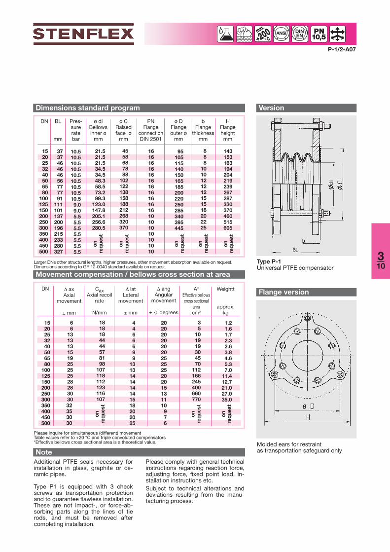
Dimensions standard program
1520253240506580
100125150200250300350400450500
66
13131315192525252828303032353030
1818184444578198
107118112123116107
4466699
1313141414141518202025
202020202020252525202015131110976
DN angAngular
movement
± � degrees
latLateral
movement
± mm
Please inquire for simultaneous (different) movement Table values refer to +20 °C and triple convoluted compensators*Effective bellows cross sectional area is a theoretical value.
Movement compensation / bellows cross section at area
P-1/2-A07
Version
Additional PTFE seals necessary forinstallation in glass, graphite or ce-ramic pipes.
Type P1 is equipped with 3 checkscrews as transportation protectionand to guarantee flawless installation.These are not impact-, or force-ab-sorbing parts along the lines of tierods, and must be removed aftercompleting installation.
Note
ANSI DINEN
PNFlange
connectionDIN 2501
161616161616161616161610101010101010
35
101919304570
112166245400660770
1.21.61.72.32.63.84.65.37.0
11.412.721.027.035.0
310
200°
Larger DNs other structural lengths, higher pressures, other movement absorption available on request.Dimensions according to GR 12-0040 standard available on request.
Type P-1Universal PTFE compensator
Flange version
Molded ears for restraintas transportation safeguard only
axAxial
movement
± mm
CaxAxial recoil
rate
N/mm
Please comply with general technicalinstructions regarding reaction force,adjusting force, fixed point load, in-stallation instructions etc.Subject to technical alterations anddeviations resulting from the manu-facturing process.
on
req
uest
on
req
uest
on
req
uest
on
req
uest
on
req
uest
on
req
uest
on
req
uest
on
req
uest

Rubber compensator with PTFE lining ■ Type Ai-2Lateral compensator DN 32 – DN 300
Ai-2/1-A07
ANSI DINEN100
°
Version■ Flanges with stabilizing collar and
ears to carry the tie rods■ Flange drilling for through bolts■ Special turned groove for rubber rimDimensionsStandard: DN 32 - DN 175 (PN 16)
DN 200 - DN 300 (PN 10) according to DIN 2501
Others: DIN EN, ANSI, BS etc.Connection dimensions see technicalannex
FlangesMaterialsStandard: 1.0038 (RSt 37-2)Others: 1.4541, 1.4571Corrosion protectionStandard: DN 32 – DN 150
electrogalvanized DN 175 – DN 300 anti-corrosion primed
Others: hot-dip galvanized, specialvarnish, special coating,etc.
Certificates
Accessories■ Internal guide sleeve of PTFE■ Protective cover
■ CE (DGR 97/23/EC)
Lateral compensator consisting of arubber bellows with seamless PTFElining and rotating flanges, also withtie rods (outer restraints) to absorb re-action force from internal pressure
Structure type Ai-2
Tie rod restraints■ DN 20 – DN 150 Tie rods carried
on silencing rubber sockets■ DN 175 – DN 300 Tie rods carried
on spherical washers and conicalseats
MaterialsStandard: tie rods 8.8Others: stainless steel Corrosion protectionStandard: electrogalvanizedOthers: hot-dip galvanized
311
STENFLEX type Ai-2 with PTFE liningin a beverages rack
Material grade* Colour code Possible uses
EPDM/PTFE orange with stamp”PTFE-Inliner“
Chemicals, acids, lyes
*Check or inquire about the resistance of the rubber grade to temperature and medium
Rubber bellows with PTFE lining PN 6■ Flat-convoluted molded bellows made of EPDM■ Synthetic fibre reinforcement■ Wire-reinforced rubber rim■ Seamless PTFE lining with self-sealing flared ends, from DN 50 with inner
PTFE supporting ring
Max. operating pressure to be set 30 % lower for shock loads.*> +90 °C the manufacturer's approval must be obtained for the corresponding operating conditions
Max. perm. operatingpressureBursting pressureVacuum
6 bar
≥ 20 barnot suitable for vacuum
up to +90 °Cup to +100 °C for brief periods*
Property Pressure Temperature
■ for conveying aggressive media■ very good chemical resis-
tance■ resistant to most acids and
lyes■ for compensating lateral move-
ment■ for muffling vibration and noise
Applications
■ for reducing thermal and mechanical tension
■ to compensate for installationinaccuracies
■ chemical industry■ beverages industry

3240506580
100125150175200250300
125125125125150150150150150175175200
3240526880
101128154177203253304
728195
115127151178206230260313363
788697
113135160184212236265318373
DN BL*
mm
666666666666
Pres-surerate
bar
ø diBellowsinner ø
mm
ø CRaisedface ø
mm
Weight
approx.kg
ø WConvolutionø unpres-
surizedmm
140150165185200220250285315340395445
ø DFlangeouter ø
mm
161616182020222222242628
bFlangethick-nessmm
*DN 32 - DN 300 also available as type Ri-2, length 130.For manufacturing reasons the inner diameter may vary by ± 3 or ± 5 mm
Dimensions standard program Versions
3240506580
100125150175200250300
888888888888
DN latLateral
movement
± mm
Movement compensation
Ai-2/2-A07
ANSI DINEN100
°
PNFlange
connec-tion
DIN 2501
161616161616161616101010
5.95.97.18.69.5
11.414.617.620.224.028.435.0
Please comply with the general tech-nical instructions regarding reactionforce, moving force, fixed point load,installation instructions etc.Subject to technical alterations anddeviations resulting from the manu-facturing process.
Note
Type Ai-2Lateral compensator with PTFE lining,with tie rods (outer restraints) carriedon silencing rubber sockets.
Type Ai-2Lateral compensator with PTFE lining,with tie rods (outer restraints) carriedon spherical washers and conicalseats.
Flange versions
Number of tie rods depending on pres-sure
DN 25 - DN 150
DN 175 - DN 300
220230240260300350385420450440495545
HFlangeheight
mm
312

PTFE compensator ■ Type P-2 and P-4Lateral compensator DN 15 – DN 500
■ for conveying aggressive media■ for compensating lateral move-
ment■ for muffling vibration and noise ■ for reducing thermal and
mechanical tension■ to compensate for installation
inaccuracies■ chemical industry■ treatment and disposal tech-
nology■ pharmaceutical industry
Applications
P-2/-4/1-A07
ANSI DINEN
PTFE bellows PN 5,5 / PN 9 / PN 10,5
Material grade* Possible uses
PTFE Aggressive acids and lyes, e.g. chloride, sulphate, solvents,bleaches, peroxide, fuels, gases
*Check or inquire about the resistance of the rubber grade to temperature and medium
Lateral compensator consisting of aPTFE bellows and rotating flangeswith tie rods (outer restraints) to ab-sorb reaction force from internal pres-sure
Structure type P-2
■ Multiple convolution bellows made of PTFE■ Outer stabilizing rings of stainless steel between the convolutions■ Self-sealing PTFE flared ends■ Inner surface repellent of foreign matter
Lateral compensator consisting of aPTFE bellows and rotating flangeswith tie rods (outer and inner re-straints) to absorb reaction force frominternal pressure or vacuum
Structure type P-4
Tie rod restraints■ Tie rods carried on spherical
washers and conical seatsMaterialsStandard: tie rods 8.8Others: stainless steel Corrosion protectionStandard: electrogalvanizedOthers: hot-dip galvanized
313
200°
FlangesVersion■ Rotating flanges with ears to carry
tie rods■ Drilled with threaded holesDimensionsStandard: DN 25 - 150 (PN 16)
DN 200 - 500 (PN 10)according to DIN 2501
Others: DIN EN, ANSI, BS etc. Connection dimensions see technicalannex
MaterialsStandard: 1.0038 (RSt 37-2)Others: 1.4541, 1.4571Corrosion protectionStandard: electrogalvanizedOthers: hot-dip galvanized, special
varnish, special coating,etc.
Max. operating pressure to be set 30 % lower for shock loads.
DNPressure rateMax. perm. operatingpressure
Vacuum
DN 200 - 500 DN 125 - 150 DN 15 - 100 Temperature PN 5,5 PN 9 PN 10,5
5.5 bar3.5 bar2.5 bar1.7 bar
9.0 bar5.5 bar4.0 bar2.5 bar
10,5 bar7 bar4 bar3 bar
up to +20 °Cup to +100 °Cup to +150 °Cup to +200 °C
≥ 0.01 bar abs. DN 15 - 150≥ 0.20 bar abs. DN 200 - 250≥ 0.70 bar abs. DN 300 - 500
Accessories■ Internal guide sleeve of PTFE■ Protective cover

1520253240506580
100125150200250300350400450500
373746464656777791
111101137200196215233280327
4558687888
102122138158188212268320370
95105115140150165185200220250285340395445
888
1010121212151518202225
143153163194204219239267287330370460515605
DN BL
mm
10.510.510.510.510.510.510.510.510.59.09.05.55.55.55.55.55.55.5
Pres-sureratebar
ø diBellowsinner ø
mm
ø CRaisedface ømm
ø DFlangeouter ø
mm
Weight
approx. kg
bFlange
thicknessmm
HFlangeheightmm
Dimensions standard program
1520253240506580
100125150200250300350400450500
4466699
13131414141415
DN latLateral
movement
mm
Table values refer to +20 °C and triple-convolut-ed compensators
Movement compensation
P-2/-4/2-A07
Versions
Additional PTFE gaskets necessaryfor installation in glass, graphite or ce-ramic pipes.Please comply with the general tech-nical instructions regarding reactionforce, moving force, fixed point load,installation instructions etc.Subject to technical alterations anddeviations resulting from the manu-facturing process.
Note
ANSI DINEN
PNFlange
connectionDIN 2501
161616161616161616161610101010101010
1.72.12.32.83.14.35.15.87.5
11.913.221.527.735.8
Flange version
314
200°
Type P-2Lateral PTFE compensator, with tierods (outer restraints) carried onspherical washers and conical seats
Type P-4 Lateral PTFE compensator, design astype P-2, addional inner restraints,carried on spherical washers andconical seats.
Number of tie rods depending onpressure
21.521.521.534.534.548.358.573.299.3
123.0147.8205.1256.6280.5
on
req
uest
on
req
uest
on
req
uest
on
req
uest
on
req
uest
on
req
uest
on
req
uest
C
Larger sizes (DN), other lengths (BL), higher pressure rate, different movement compensation availableon requestDimensions according to GR 12-0040 standard available on request.