steeroids™ installation instructions
TRANSCRIPT

1
1
We are constantly updating our instructions, so check for the latest version at http://speeddirect.com/index.aspx?nodeID=79.NOTES ON TURNING RADIUS: The turning radius with our kit is slightly increased over stock. Most customers have said it is an
insignificant amount, if not unnoticeable. You will still be able to easily whip in and out of parking spots or driveways.
PART NO. SHEET OF561127, 561084
800-345-4122 PART NO. SHEET OF561127, 561084
INSTALLATION INSTRUCTIONSDATE REVISION AUTH DR
7/18/2013
10
10
PARTS Steeroids™ INSTALLATION INSTRUCTIONS
PLEASE NOTE: These components are tested and engineered to meet loads equal to what the stock steering system is exposed to during normal operation. If you or the person or firm you hire to install your Steeroids rack & pinion kit believes it is necessary to “modify” any compo-nents to make them fit and /or adjust properly PLEASE note that this is extremely dangerous. We offer free technical phone support to assist with installation should you encounter a problem. Modifications may include cutting or welding support brackets, sawing or hammering on ujoints,
or any revision, deletion or addition to the product as delivered, and should NEVER be required. Any such modifications void the manufacturers warranty. Our knowledgeable staff will gladly assist you with any questions you may have during installation. In addition Class M Corporation, DBASpeedDirect is not responsible or liable for any damages or injury resulting from any modification to the components as delivered.
Verify Kit Contents:1 RACK AND PINION WITH 2 RUBBER RACK BUSHINGS2 RACK MOUNTING CLAMPS2 TIE ROD ENDS W/ TAPERED STUDS3 ROD ENDS (INCL. SUPPORT BEARING)2 ALUMINUM TIE ROD SLEEVES1 U-JOINT, 3/4” 36 SPLINE X 17MM DD2 U-JOINT, 3/4” 36 SPLINE X 36 SPLINE1 U-JOINT SHAFT, ALUM. 3/4” 36 SPLINE x 5 5/8”1 U-JOINT SHAFT, ALUM. 3/4” 36 SPLINE x 8 3/8”1 DRIVER’S SIDE BRACKET1 PASSENGER’S SIDE BRACKET1 TIEROD BRACKET1 RADIATOR SUPPORT BRACKET1 BEARING BRACE BRACKET2 METRIC RACK BOLTS & NORD LOCK WASHERS1 FASTENER KIT BAG (INCL. BOLTS, NUTS, WASHERS)
Not provided by SpeedDirect if you orderedfrom Corvette Central: 1 STEERING COLUMN1 STEERING COLUMN WIRING KIT1 STEERING COLUMN STEERING WHEEL ADAPTER
Additional Parts Included With Power Kits:3 PUMP HOSES, 1 PRESSURE, 1 RETURN, 1 REMOTE RES.1 PULLEY, 5 INCH, 1 GROOVE TYPE II ALUM1 PUMP, 53-62 CORVETTE1 PUMP BRACKET1 RESERVOIR1 RESERVOIR MOUNT
1
2
2
PART NO. SHEET OF561127, 561084
800-345-4122 PART NO. SHEET OF561127, 561084
INSTALLATION INSTRUCTIONSDATE REVISION AUTH DR
7/18/2013
10
10
PARTS Steeroids™ INSTALLATION INSTRUCTIONS
BEFORE BEGINNING: Please note each steering rack is bench tested prior to shipping therefore some of the fluid from the test
occasionally leaks out and may stain the box. This does not mean the rack has been damaged if fluid has leaked out.
You may also find two small rubber o-rings attached to your rack with a twist tie, these are merely extras that are sometimes
supplied with our steering racks. The power steering hose adapters supplied with your kit should already have o-rings attached, so
the extras can be discarded. Due to the various suppliers we use, any bolts, metal plates and/or washers that are already threaded
into the rack unit should be discarded and our included metric rack bolt kit should be used.
If the vehicle requires a new crank pulley with an extra groove for the PS pump, there is no crank pulley included with the kit. This
kit is installing onto a 50 year old car with an unknown combo of engine, pulleys and water pump, so there is no possible ‘standard’
one-size-fits-all solution for so many variables. Please see “C1 Corvette Crank Pulley Information” document (page 7 and 8 of
these instructions) on crank pulley specifications to determine the correct crank pulley for the vehicle. Note that the pump pulley
requires a special tool to be mounted to the pump before installation. If you do not have this tool, most auto parts stores can do this for you.
If the Alternator / Generator is located on the driver’s side of the car there will be a clearance issue with the power steering pump.
The customer will need to relocate the alt/gen to the driver’s side using Corvette Central (find them at www.corvettecentral.com) (MOUNTING
ADAPTOR PLATE - RIGHT GENERATOR / ALTERNATOR WITH HEADERS) and 302015 (ALTERNATOR SUPPORT BRACKET - RIGHT). The cus-tomer may not need both brackets, the customer will need to double check.
BEFORE INSTALLATION: Begin by performing an inventory of allthe components in the kit with the above list. Installing the Steeroidskit requires simple hand tools, high strength thread locker and someanti seize compound. A pickle fork will be useful whendisassembling the old system.1 . Begin by jacking the car up andsupporting it properly with jack stands.Never support the car usingonly a jack. Remove the front wheels and the hood.
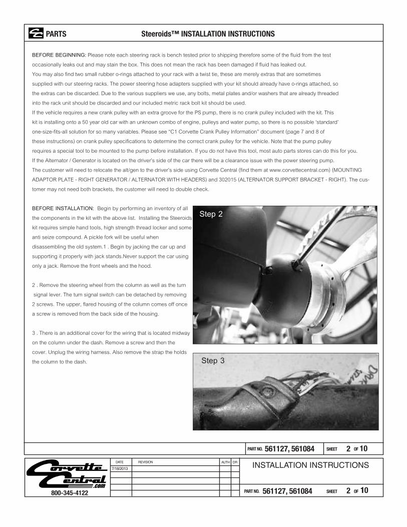
2 . Remove the steering wheel from the column as well as the turn signal lever. The turn signal switch can be detached by removing2 screws. The upper, flared housing of the column comes off oncea screw is removed from the back side of the housing.
3 . There is an additional cover for the wiring that is located midway
on the column under the dash. Remove a screw and then thecover. Unplug the wiring harness. Also remove the strap the holdsthe column to the dash. Step 3
Step 2

3
3
4. In the engine compartment you can disconnect the steering arm from the
rest of the linkage and unbolt the steering box from the frame. Now unbolt the
fire wall plate and remove the steering column. As you pull the column out of
the firewall you will need to orient the wiring so that it lays flat so it can pass
through the firewall opening. Pulling the steering box and column will be a
careful balance of rotating and tilting to get it clear of the radiator support.
This may also require changing the position of the steering arm by rotating
the column shaft.
5. Remove the cotter pins and castle nuts from the outer tie rods and remove
them from the steering arms. Next, remove the center pivot/radiator support.
You may need to completely unbolt the radiator and raise it 2 or 3 inches in
order to gain access to the middle two frame bolts. Caution: the pivot and
steering linkage are very heavy. Be careful to support it as you unbolt it.
InstallationWe recommend using red high strength thread lock on all threadedapplications except for power steering hose fittings and tie rod sleeves.Be SURE to trial fit first, and read the instructions through before going crazywith the thread lock!6. With all the stock steering removed you can begin by installing themounting brackets. The radiator support bracket installs where the centerpivot was before. It uses the same holes in the frame and the 4 supplied3/”8 bolts and nuts.7. The passenger side bracket sandwiches between the frame rail and theengine mount. Be sure to support the engine before you remove the four bolts (2 on top of the frame rail, 2 on the bottom). Loosen the bolt that pinches the rubber mount between the frame bracket and the engine bracket. Don’t remove the bolt.8. Now slide the Steeroids passenger side bracket in place between the frame and the engine mount bracket and install the 4 boltsthat were removed in the previous step. Once tightened to 30 ft/lbs you can re-tighten the rubber mount bolt.
Step 4
Step 6
Step 7 Step 8
PART NO. SHEET OF561127, 561084
800-345-4122 PART NO. SHEET OF561127, 561084
INSTALLATION INSTRUCTIONSDATE REVISION AUTH DR
7/18/2013
10
10
PARTS Steeroids™ INSTALLATION INSTRUCTIONS

4
4
9. The driver’s side bracket slides up from the bottom. The lower bolt hole uses a 3/8 x 4” long bolt. Install this bolt now.10. Next the bearing support bracket installs over the top of the frame rail and the driver’s side bracket. 2 ea 3/8 x 4.5” bolts secure this and the driver’s side bracket.11. To center the rack unit, use an adjustable wrench and turn the pinion until the rack is at its stop. Now count the turns as you proceed to the opposite stop. Divide the number you get by 2 and turn the pinion back this amount. The steering rack is now centered.12. Bolt the tie rod bracket to the rack and pinion unit using the supplied bolts (metric), and the Nord lock washers (two-piece, ser-rated). The bracket installs with the outer holes toward the top of the steering rack. It can be installed upside down, so be sure you have the correct orientation as shown in the picture below. NOTE: If the rack came with bolts, washers and a french lock already threaded into it, discard these items including the washers that may be stuck onto the boot, and use the longer black rack bolt kit #690-50063. Also, the tie rod bracket will compress the black rubber boot, this is normal. Use a high-strength thread locker and torque to 60 ft/lbs.
About Nord-Lock Washers
13. Please note: there are right hand and left hand threads on the aluminumsleeves. Apply anti-seize compound on the rod end and sleeve threads. Thread each tie rod end with jam nut onto the tie rod sleeves an equal amount. On the other end of each sleeve, thread the remaining 5/8” rodends with jam nuts. Attach them to the tie rod bracket using the 5/8-18 x 1.5 bolts and lock washers. The lock washer is located betweenthe head of the bolt and the inner tie rod bearing. Use a high strengththread locker and torque to 50 ft/lbs. If you experience clearance issueswith the head of the 5/8 bolt, you can omit the lock washer but be sure to use high strength thread locker. Trial fit BEFORE the thread lock. To set an approximate alignment, measure the overall length of the old steering system. Measure from the center of each outer tie rod. Adjust the tie rods on the steering rack to match your measurement and tighten the jam nuts against the sleeves.
Tie rod assembly
Right hand threads Left hand threads
Step 9 Step 10
PART NO. SHEET OF561127, 561084
800-345-4122 PART NO. SHEET OF561127, 561084
INSTALLATION INSTRUCTIONSDATE REVISION AUTH DR
7/18/2013
10
10
PARTS Steeroids™ INSTALLATION INSTRUCTIONS
NORD-LOCK is a pair of washers with awedge-locking action meeting DIN 25201 which is a unique method using tension instead of friction. The rise of the cams between the NORD-LOCKwashers is greater than the pitch of the bolt. In addition, there are radial teeth on the opposite side. The washers are installed in pairs, camface to cam face.
Step 12

14. Install the braided return line on the top rack port nearest to the pinion (the smallest hole). Now install the rack and pinion on the brackets using the supplied clamps and 5/16 x 1” bolts,washers and nuts. Please note the 2 rack clamps provided are shaped differently - they must fitproperly on the rack. Torque the pass. side bolts to 30 ft-lbs but leave the driver side loose untilcompleting step 17. Now proceed to attach the outer tie rod ends to the steering arms (spindles).Before torquing, read the following details. NOTE: the flange below the taper may not seat againstthe steering arm- this is not a problem. If your car has two holes in the steering arm install the tierod end in the hole closest to the front of the car. Using the hole towards the rear will increase thesteering radius. properly outer To adjust the tie rods, use the included bump steer spacers. Startwith half above and half below the tie rod end bearing. As needed, move the spacers above orbelow the bearing so that the entire length of the tie rod matches the angle of the lower control armwith the vehicle on the ground and the suspension settled (the tie rod sleeve should be parallel with the lower control arm pivot points - not necessarily the ground). You may need to come back and adjust this once installation is complete, especially if no engine is installed. Torque the upper nut to 30 ft/lbs and the lower nut to 50 ft/lbs. .
5
5
15. Now install the steering column by sliding the small end through the firewall from the inside of the car. First plug in the supplied wiring harness to the column and the corresponding connectors on the car. Use the original column clamp to secure the column to the dash but do not completely tighten until the following step.
16. Install the turn signal lever and hazard button on the column and clock it to the proper ori-entation. Tighten the column clamp. Next install the steering wheel/column adapter so that the horn connections line up and the turn signals cancel equally when the wheel is turned left and right. Do not fully tighten the steering wheel nut until the entire steering system is in-stalled and the front wheels are pointed straight with the wheel and rack unit centered.
Step 14 Step 14a
Step 14b
Step 15
PART NO. SHEET OF561127, 561084
800-345-4122 PART NO. SHEET OF561127, 561084
INSTALLATION INSTRUCTIONSDATE REVISION AUTH DR
7/18/2013
10
10
PARTS Steeroids™ INSTALLATION INSTRUCTIONS
6
6
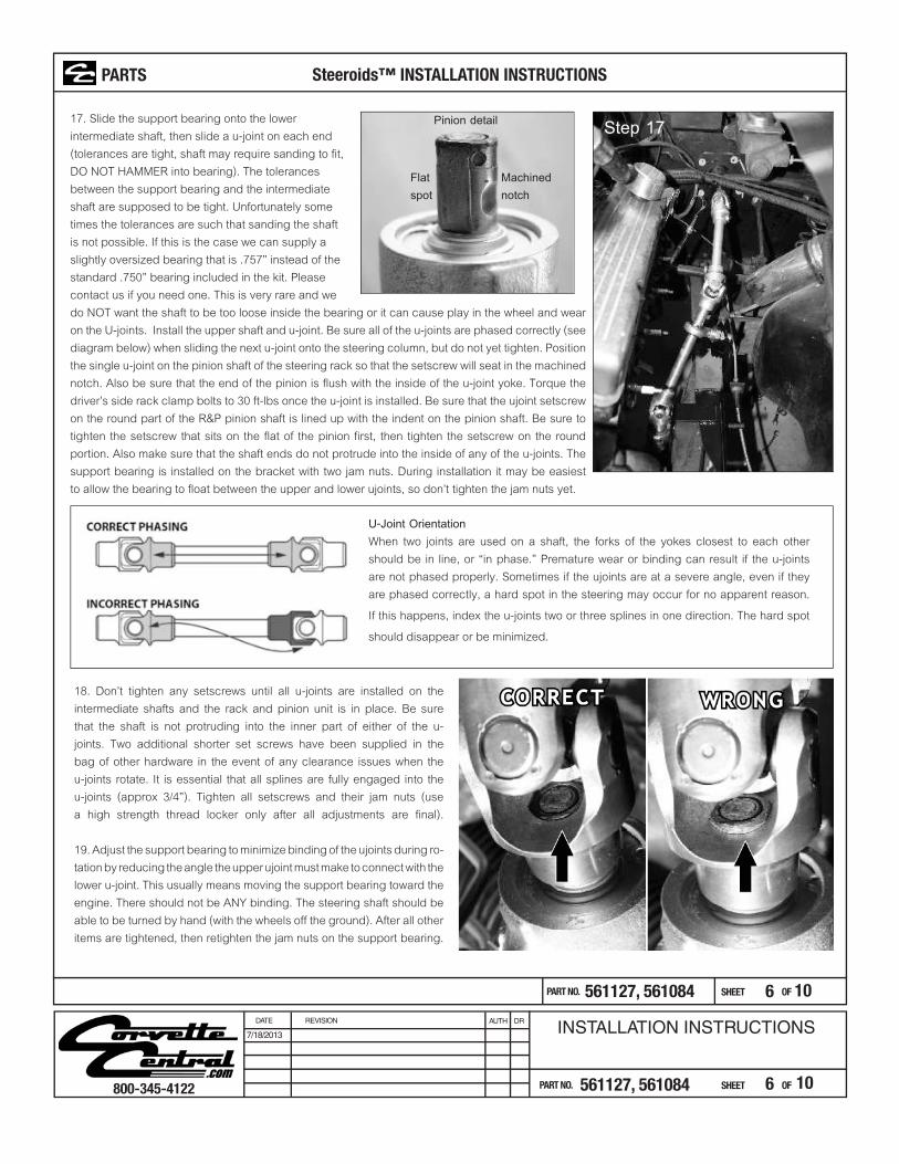
17. Slide the support bearing onto the lowerintermediate shaft, then slide a u-joint on each end(tolerances are tight, shaft may require sanding to fit,DO NOT HAMMER into bearing). The tolerancesbetween the support bearing and the intermediateshaft are supposed to be tight. Unfortunately sometimes the tolerances are such that sanding the shaftis not possible. If this is the case we can supply aslightly oversized bearing that is .757” instead of thestandard .750” bearing included in the kit. Pleasecontact us if you need one. This is very rare and wedo NOT want the shaft to be too loose inside the bearing or it can cause play in the wheel and wear on the U-joints. Install the upper shaft and u-joint. Be sure all of the u-joints are phased correctly (see diagram below) when sliding the next u-joint onto the steering column, but do not yet tighten. Position the single u-joint on the pinion shaft of the steering rack so that the setscrew will seat in the machined notch. Also be sure that the end of the pinion is flush with the inside of the u-joint yoke. Torque the driver’s side rack clamp bolts to 30 ft-lbs once the u-joint is installed. Be sure that the ujoint setscrew on the round part of the R&P pinion shaft is lined up with the indent on the pinion shaft. Be sure to tighten the setscrew that sits on the flat of the pinion first, then tighten the setscrew on the round portion. Also make sure that the shaft ends do not protrude into the inside of any of the u-joints. The support bearing is installed on the bracket with two jam nuts. During installation it may be easiest to allow the bearing to float between the upper and lower ujoints, so don’t tighten the jam nuts yet.
Step 17Pinion detail
Flatspot
Machinednotch
PART NO. SHEET OF561127, 561084
800-345-4122 PART NO. SHEET OF561127, 561084
INSTALLATION INSTRUCTIONSDATE REVISION AUTH DR
7/18/2013
10
10
PARTS Steeroids™ INSTALLATION INSTRUCTIONS
U-Joint OrientationWhen two joints are used on a shaft, the forks of the yokes closest to each other should be in line, or “in phase.” Premature wear or binding can result if the u-joints are not phased properly. Sometimes if the ujoints are at a severe angle, even if they are phased correctly, a hard spot in the steering may occur for no apparent reason. If this happens, index the u-joints two or three splines in one direction. The hard spotshould disappear or be minimized.
18. Don’t tighten any setscrews until all u-joints are installed on the intermediate shafts and the rack and pinion unit is in place. Be sure that the shaft is not protruding into the inner part of either of the u-joints. Two additional shorter set screws have been supplied in the bag of other hardware in the event of any clearance issues when the u-joints rotate. It is essential that all splines are fully engaged into the u-joints (approx 3/4”). Tighten all setscrews and their jam nuts (use a high strength thread locker only after all adjustments are final).
19. Adjust the support bearing to minimize binding of the ujoints during ro-tation by reducing the angle the upper ujoint must make to connect with the lower u-joint. This usually means moving the support bearing toward theengine. There should not be ANY binding. The steering shaft should be able to be turned by hand (with the wheels off the ground). After all other items are tightened, then retighten the jam nuts on the support bearing.

7
7
20. Install the power steering pump and reservoir. Mount the pump bracket to the front of the engine block using the supplied bolts. Now install the pump onto the bracket. There is only a small amount of adjustment, this is OK, it’s enough.
21. The reservoir mounts to the inner fender well and the return line connects from the bot-tom of the reservoir to the bottom of the pump (the largest hose). Be sure to lubricate all O-rings with a small amount of power steering fluid before installation. Now connect the high pressure line from the top of the pump to the lower, inboard port on the steering rack. Seephoto at left and supplemental hose instructions in the hose package. Next connect the return line from the rack to the reservoir.
Some power steering pumps will need to havethe threads drilled out in these locations. Use a
5/16” or 21/64” drill bit so the bolt can slide through
This shows how the high pressurehose banjo fitting is installed
22. Fill the reservoir 2/3 with new power steering fluid and turn the pump pulley by hand a few time to introduce fluid into the pump. Run stan-dard GM Power Steering Fluid. For those who prefer synthetic fluids you may switch to Royal Purple Synthetic after 1000 miles, but it is not required.
23. Now install the V-belt and bleed the system by turning the wheels all the way to the left. Turn the wheel back and forth 3 or 4 times. Start the car and allow it to idle.(A) Now turn the wheels side to side (nearly to the steering stops) until there are no more bubbles. Check the fluid level frequently while proceeding. Allow the en-gine to run for a few minutes. Add fluid as needed until the reservoir is filled 2/3 of the way. Replace cap and shut off engine. If the fluid level rises after the en-gine is shut off, there is still air in the system. Repeat (A) until all air is out of the system. “Flushing” the system is not necessary, you are only bleeding it of air.
top view of house routingtop view of house routing
PART NO. SHEET OF561127, 561084
800-345-4122 PART NO. SHEET OF561127, 561084
INSTALLATION INSTRUCTIONSDATE REVISION AUTH DR
7/18/2013
10
10
PARTS Steeroids™ INSTALLATION INSTRUCTIONS
Step 20
8
8
PART NO. SHEET OF561127, 561084
800-345-4122 PART NO. SHEET OF561127, 561084
INSTALLATION INSTRUCTIONSDATE REVISION AUTH DR
7/18/2013
10
10
24. Now re-check every bolt and nut to be sure all are tight and torqued. Test-drive the car at low speed for a brief period. Check every bolt for tightness again. For power kits only: If the engine is at operating temperature, check the power steering fluid level. Fill to the “hot” mark as needed.CAUTION: The steering ratio of this kit is significantly faster than the stock steering. Exercise caution when first driving with the new system. The vehicle will respond quicker and turn more from the same amount of steering input. This might take some time to get used to.
25. The final step is to have the front end aligned to the specs below and re-check all bolts for tightness after the first 100 miles. If the person install-ing the kit ignores these recommendations and it is aligned to factory specs, the car will handle very poorly. This is VERY important.
DETAILS FOR ALIGNMENT: Camber Caster ToeStreet 0 -.25 negative camber 2.5 - 5 positive 0 to 1/8” toe in
***Please Note: The rack unit that we are using for this kit has some movement built into the rack. When the vehicle goes in foralignment, you may notice the center tie rod bracket can move up and down a slight amount, affecting the toe of the vehicle. THISIS NORMAL. The GM rack we are using had this movement built into it from the factory. Do not try to move the bracket all the wayto one side or the other of this movement when aligning the vehicle. Leave the bracket in the location it was at when the vehiclewas pulled forward onto the lift and adjust it from there.
Warning: FAILURE TO ADJUST THE UPPER U-JOINT SO THAT THERE IS NO BINDING WILL RESULT IN PREMATURE WEAR AND FAILURE! IF YOU FEEL ANY BINDING / LUMPINESS / HARDNESS IN THE STEERING WHEEL WHILE TURNING, ADJUSTMENT IS STILL REQUIRED AS DETAILED IN STEP 19Additional tech support and info can be found online at speeddirect.com
STEEROIDS WARRANTYAll Steeroids Rack & Pinion Conversion Kits (the Kit) purchased from Class M Corporation, DBA SpeedDirect, hereafter SpeedDirect or an authorized reseller are warranted, subject to limitations and exceptions defined herein, against defects in materials and workmanship for a period of five years from the date of shipment from the SpeedDirect warehouse. During this five-year period, SpeedDirect will repair or replace any covered component found to be defective at no charge to the purchaser except freight costs which will be assessed for any claim made after 30 days from to original purchase date. All claims shall be sent to and from the nearest SpeedDirect office. Any and all costs for inspection, removal or replacement of the Kit or its constituent parts or assemblies under this warranty are the responsibility of the original purchaser.This warranty does not apply to equipment which in the judgment of SpeedDirect was used in racing or has been subjected to misuse, accidental or intentional damage, or has been installed in a manner or under conditions other than those expected in a normal driving. This warranty is also void if the equipment has been modified (unless such modification has been expressly approved in writing by SpeedDirect).Warranty applies only to the original purchaser. Purchaser is responsible for retaining the original Sales Invoice for the Kit as proof of purchase which shall be presented to SpeedDirect in order to receive any consideration of repair or replacement as defined within this warranty.Exceptions & limitations to this warranty are: SpeedDirect may, at its sole discretion, extend warranty coverage on any product or assembly item beyond these stated limits on a case-by-case basis. This warranty is in lieu of all others expressed or implied, and no representative or person other than a corporate officer of Class M Corporation is authorized to assume any liability other than that expressed herein on behalf of Class M Corporation, DBASpeedDirect. SpeedDirect accepts no liability for loss of service, loss of revenue, or any special or consequential damages that may arise from the failure or malfunctions of its products. Defective products or components shall only be returned to the SpeedDirect repair facility after receiving a written Return Authorization and shipping instructions.
STEEROIDS REPLACEMENT POLICYLabor charges and/or damage incurred in installation, repair or replacement as well as incidental and consequential damages connected there with are excluded and will not be paid by seller. Any and all costs for inspection, removal or replacement of the kit or its constituent parts or assemblies under this warranty are the responsibility of the original purchaser. SpeedDirect 1901 S. FM 129, Santo, TX 76472 Tech Line (970) 731-1381 dept. 2
STOP
PARTS Steeroids™ INSTALLATION INSTRUCTIONS

9
9
PART NO. SHEET OF561127, 561084
800-345-4122 PART NO. SHEET OF561127, 561084
INSTALLATION INSTRUCTIONSDATE REVISION AUTH DR
7/18/2013
10
10
C1 Corvette crank pulley informationThe power steering pump and bracket supplied with the kit is designed to work with a crank pulley that has a second groovethat measures between 1.3” and 1.5” from the face of the harmonic balancer. A pulley diameter ranging from 5” to 6.75” willwork. Important information to know about the crank pulley: - Crank Pulley must be for a short style water pump - Crank Pulley must have two grooves - Does not need a 2 groove water pump pulley but will work with one - May require water pump pulley shims (see below) - May require crank pulley shims (see below)Suggestions for crank pulleys are as follows:
Trans Dapt 9481 aluminum Mr. Gasket 4973 steel (chrome)
Moroso 64060 cast aluminum Spectre 4399 aluminum
- Billet Specialties 81220 aluminum
Moroso #710-64061 aluminum
PARTS Steeroids™ INSTALLATION INSTRUCTIONS

10
10
PART NO. SHEET OF561127, 561084
800-345-4122 PART NO. SHEET OF561127, 561084
INSTALLATION INSTRUCTIONSDATE REVISION AUTH DR
7/18/2013
10
10
CRANK PULLEY SHIM KITS:Shims are available to change the dimension of the crank pulley. Shims or a single washer thickness can be placed betweenthe pump mount and the engine block.Canton 74-900 crank pulley shim kit. One each of 1/16 in., 1/8 in., and 3/16 in. thick shims.
JEGS #555-50400 crank shim kit. 1/16”, 5/64” and 1/8”
WATER PUMP SHIM KITS:JEGS #555-51106 two 1/16’’ and one 1/8’’Spectre 4480 1/16’’, 1/8’’ or 3/16’’
JEGS #555-51106 two 1/16’’ and one 1/8’’
PARTS Steeroids™ INSTALLATION INSTRUCTIONS