steering towards flow optimization
TRANSCRIPT
60 mentor.com/mechanical
he ever-shortening product cycles and decreasing development times in the automotive industry raise the need for up-to-date simulation
tools equipped with reliable physical calculation methods. The use of Mentor Graphics’ FloEFD Concurrent CFD software enables an evaluation of future automotive components at the earliest possible stage during the development cycle. This allows problem identification and correction when the concept is first evaluated at the feasibility stage of the project.
Steering assistance in commercial vehicles is performed by means of a hydraulic system
T
Steering Towards Flow OptimizationBy Rolf Haegele, development engineer acoustics / simulation, Robert Bosch Automotive Steering GmbH.
FloEFD™ is an established part of the development process at Robert Bosch Automotive Steering GmbH
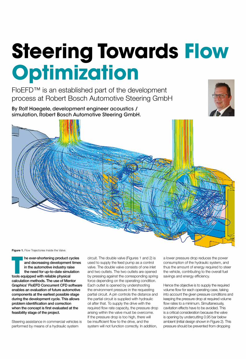
circuit. The double valve (Figures 1 and 2) is used to supply the feed pump as a control valve. The double valve consists of one inlet and two outlets. The two outlets are opened by pressing against the corresponding spring force depending on the operating condition. Each outlet is opened by undershooting the environment pressure in the requesting partial circuit. A pin controls the distance and the partial circuit is supplied with hydraulic oil after that. To supply the drive with the required flow rate capacity, the pressure drop arising within the valve must be overcome. If the pressure drop is too high, there will be insufficient flow to the drive, and the system will not function correctly. In addition,
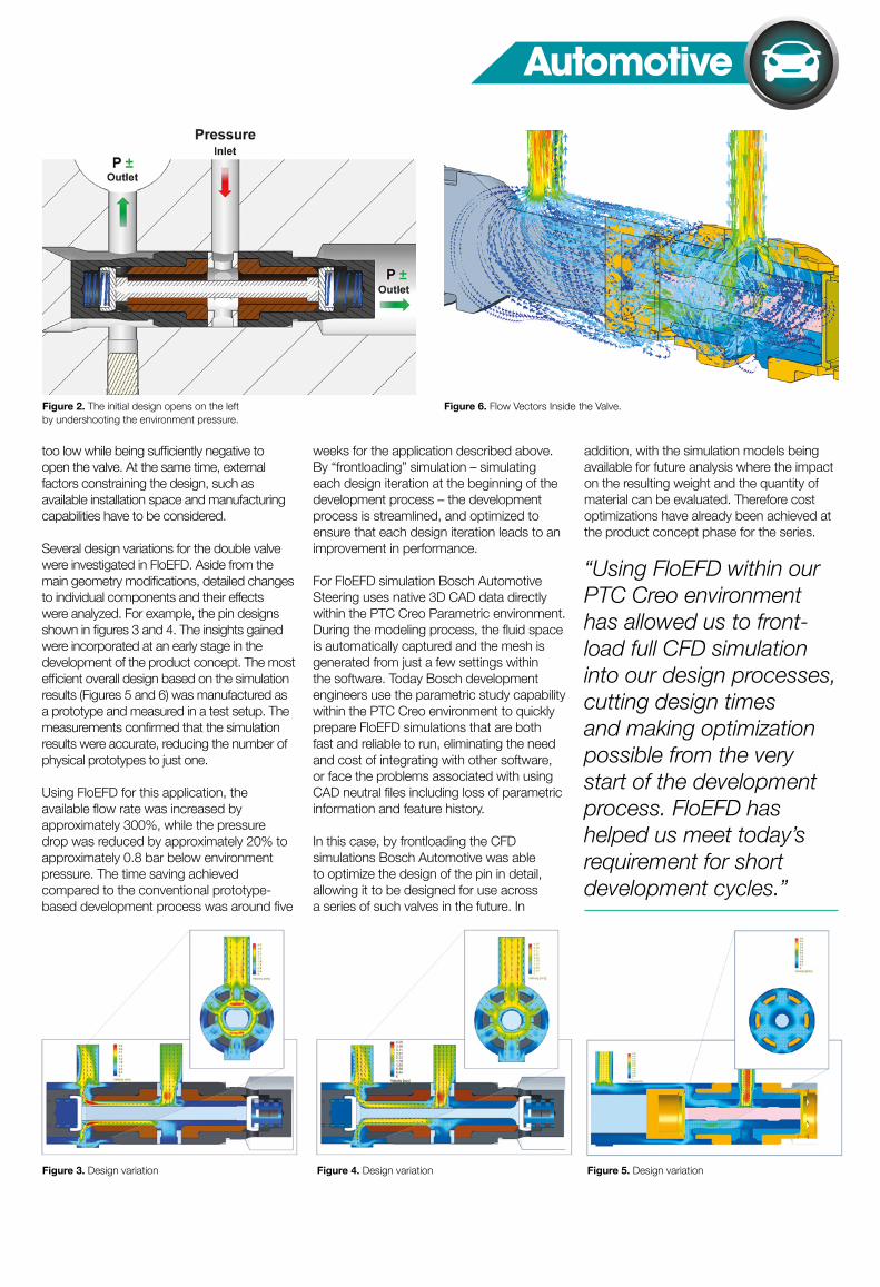
a lower pressure drop reduces the power consumption of the hydraulic system, and thus the amount of energy required to steer the vehicle, contributing to the overall fuel savings and energy efficiency. Hence the objective is to supply the required volume flow for each operating case, taking into account the given pressure conditions and keeping the pressure drop at required volume flow rates to a minimum. Simultaneously, cavitation effects have to be avoided. This is a critical consideration because the valve is opening by undercutting 0.95 bar below ambient (initial design shown in Figure 2). This pressure should be prevented from dropping
Figure 1. Flow Trajectories Inside the Valve.
mentor.com/mechanical 61
Automotive
Figure 3. Design variation Figure 4. Design variation Figure 5. Design variation
Figure 2. The initial design opens on the left by undershooting the environment pressure.
too low while being sufficiently negative to open the valve. At the same time, external factors constraining the design, such as available installation space and manufacturing capabilities have to be considered.
Several design variations for the double valve were investigated in FloEFD. Aside from the main geometry modifications, detailed changes to individual components and their effects were analyzed. For example, the pin designs shown in figures 3 and 4. The insights gained were incorporated at an early stage in the development of the product concept. The most efficient overall design based on the simulation results (Figures 5 and 6) was manufactured as a prototype and measured in a test setup. The measurements confirmed that the simulation results were accurate, reducing the number of physical prototypes to just one.
Using FloEFD for this application, the available flow rate was increased by approximately 300%, while the pressure drop was reduced by approximately 20% to approximately 0.8 bar below environment pressure. The time saving achieved compared to the conventional prototype-based development process was around five
weeks for the application described above. By “frontloading” simulation – simulating each design iteration at the beginning of the development process – the development process is streamlined, and optimized to ensure that each design iteration leads to an improvement in performance.
For FloEFD simulation Bosch Automotive Steering uses native 3D CAD data directly within the PTC Creo Parametric environment. During the modeling process, the fluid space is automatically captured and the mesh is generated from just a few settings within the software. Today Bosch development engineers use the parametric study capability within the PTC Creo environment to quickly prepare FloEFD simulations that are both fast and reliable to run, eliminating the need and cost of integrating with other software, or face the problems associated with using CAD neutral files including loss of parametric information and feature history.
In this case, by frontloading the CFD simulations Bosch Automotive was able to optimize the design of the pin in detail, allowing it to be designed for use across a series of such valves in the future. In
addition, with the simulation models being available for future analysis where the impact on the resulting weight and the quantity of material can be evaluated. Therefore cost optimizations have already been achieved at the product concept phase for the series.
Figure 6. Flow Vectors Inside the Valve.
“Using FloEFD within our PTC Creo environment has allowed us to front-load full CFD simulation into our design processes, cutting design times and making optimization possible from the very start of the development process. FloEFD has helped us meet today’s requirement for short development cycles.”