steels for bearings - university of thessaly...gonidakis st. physical metallurgy/2015-2016...
TRANSCRIPT
UNIVERSITY OF THESSALY
MECHANICAL ENGINEERING
CONTEMPORARY METHODS OF
DESING AND ANALYSIS IN
INDUSTRY
STEELS FOR BEARINGS
Material Science Engineer: Civil Engineer: St.Gonidakis K.Christopoulos
Supervisor: Gregory N. Haidemenopoulos
VOLOS, JANUARY 2016
Gonidakis St. Physical metallurgy/2015-2016 Christopoulos K.
1
Contents
1 Introduction
1.1 General Information
1.2 Types of bearings
1.3 Historical data
1.4 Rolling element of bearings
1.5 Life span of roller bearings
2 Microstructure
2.1 Overview
2.2 Grain
2.3 Crystal structure
2.4 Interstitial solid solutions
2.5 Substitutional solid solutions
3 Transformations
3.1 Phase transformation
3.2 Diffusion
3.3 Diffusion coefficient
3.5 Diffusion transformation
3.6 Martensitic transformation
4 Roller bearing technology
4.1 Low concentration of alloying elements steels
4.2 Aerospace
Conclusion
Gonidakis St. Physical metallurgy/2015-2016 Christopoulos K.
2
1 Introduction
1.1 General information
The term bearing describes an element that constrains motion and supports moving
mechanical parts, such as axles and shafts. Their main objective is to receive the loads
that are imposed during machine operations and to transfer them to their fixed parts,
such as their foundation or their reduction gearboxes. Bearings are lubricated in order
to keep friction losses and temperatures to a minimum. Friction in bearings can either
be kinetic (that does not allow for relative movement to the opposite direction
between two surfaces) or static when two objects are not moving relative to each
other.
1.2 Types of bearings
Generally there are 3 basic ways of categorizing bearings
1. Depending on the position of the shaft that they are supporting:
o Radial
o Thrust
2. Depending on the type of friction that develops :
o Rolling Element
o Plain
3. Depending on the way it is operating :
o Fixed
o Self Aligning
1.3 Historical data
Bearings have been used since ancient times in the construction of the greatest
monuments of human history. This is a quick historical overview and some milestone
dates for the development of bearings.
2600 BC - The ancient Egyptians used a type of roller bearing to move huge
stone blocks during the building of the pyramids .
40 BC -An early type of ball bearing made out of wood was used by the
Romans to support tables.
1500 AD - Leonardo DaVinci describes a type of ball bearing.
1740 AD - John Harrison invents the first caged roller bearing
1794 AD - The welsh Phillip Vaughan files a patent application for the first
modern ball bearing design.
1980 AD - NASA uses needle roller bearings on its space shuttles.
Nonetheless ,the present paper focuses more on the materials used for
creating the rolling bearings , more specifically to 1C - 1.5 Cr steel alloys ,which are
widely used .According to H Bhadeshia ,professor of metallurgy at SFK Steel
Technology Center , the performance of the particular alloys has been studied
extensively by Stribeck (1901) displaying suitability for the required applications and
with progressive improvements ,became the main alloy to be used for bearings since
1905 .It is still used today due to its excellent fatigue performance and cleanliness
Gonidakis St. Physical metallurgy/2015-2016 Christopoulos K.
3
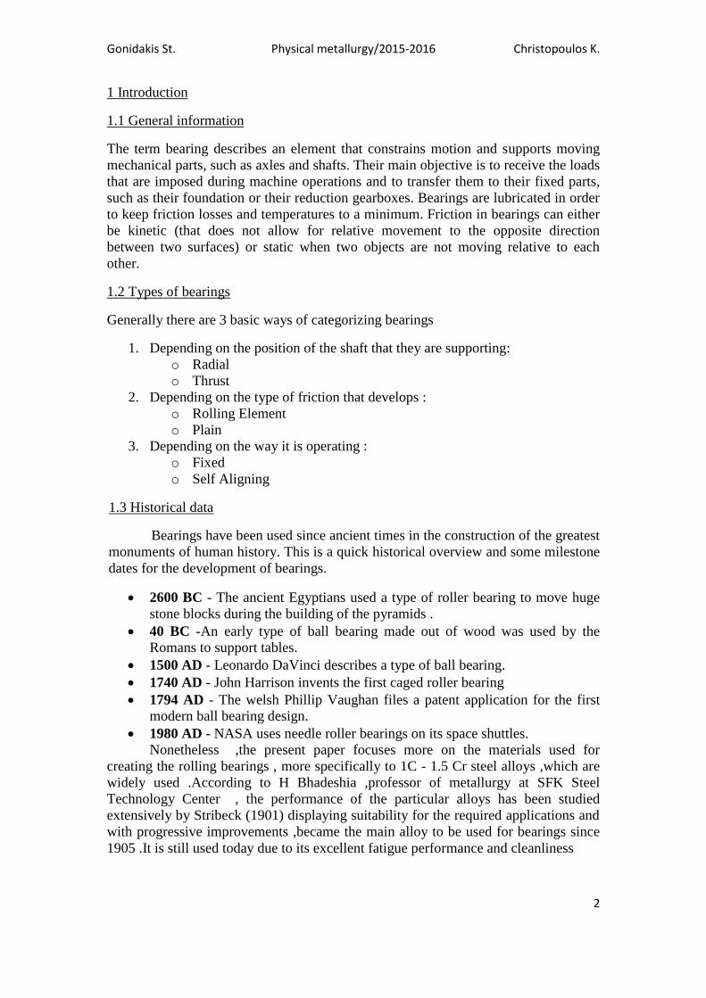
1.4 Rolling element of bearings
Rolling element bearings are comprised of two rings or discs one inner and
the other outer, shaped so that the rolling elements can move between them. The
rolling elements can be formed as a sphere, cylinder ,toroid ,tapered cylinder or
needle . There are the following five types of rolling element bearings based on the
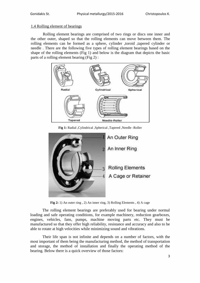
shape of the rolling elements (Fig 1) and below is the diagram that depicts the basic
parts of a rolling element bearing (Fig 2) :
Fig 1: Radial ,Cylindrical ,Spherical ,Tapered ,Needle -Roller
Fig 2: 1) An outer ring , 2) An inner ring, 3) Rolling Elements , 4) A cage
The rolling element bearings are preferably used for bearing under normal
loading and safe operating conditions, for example machinery, reduction gearboxes,
engines, vehicles, fans, pumps, machine moving parts etc. They must be
manufactured so that they offer high reliability, resistance and accuracy and also to be
able to rotate at high velocities while minimizing sound and vibrations.
Their life span is not infinite and depends on a number of factors, with the
most important of them being the manufacturing method, the method of transportation
and storage, the method of installation and finally the operating method of the
bearing. Below there is a quick overview of those factors:
Gonidakis St. Physical metallurgy/2015-2016 Christopoulos K.
4
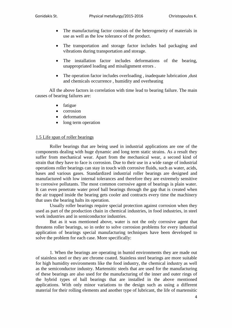
The manufacturing factor consists of the heterogeneity of materials in
use as well as the low tolerance of the product.
The transportation and storage factor includes bad packaging and
vibrations during transportation and storage.
The installation factor includes deformations of the bearing,
unappropriated loading and misalignment errors .
The operation factor includes overloading , inadequate lubrication ,dust
and chemicals occurrence , humidity and overheating
All the above factors in correlation with time lead to bearing failure. The main
causes of bearing failures are:
fatigue
corrosion
deformation
long term operation
1.5 Life span of roller bearings
Roller bearings that are being used in industrial applications are one of the
components dealing with huge dynamic and long term static strains. As a result they
suffer from mechanical wear. Apart from the mechanical wear, a second kind of
strain that they have to face is corrosion. Due to their use in a wide range of industrial
operations roller bearings can stay in touch with corrosive fluids, such as water, acids,
bases and various gases. Standardized industrial roller bearings are designed and
manufactured with low internal tolerances and therefore they are extremely sensitive
to corrosive pollutants. The most common corrosive agent of bearings is plain water.
It can even penetrate water proof ball bearings through the gap that is created when
the air trapped inside the bearing gets cooler and contracts every time the machinery
that uses the bearing halts its operation.
Usually roller bearings require special protection against corrosion when they
used as part of the production chain in chemical industries, in food industries, in steel
work industries and in semiconductor industries.
But as it was mentioned above, water is not the only corrosive agent that
threatens roller bearings, so in order to solve corrosion problems for every industrial
application of bearings special manufacturing techniques have been developed to
solve the problem for each case. More specifically:
1. When the bearings are operating in humid environments they are made out
of stainless steel or they are chrome coated. Stainless steel bearings are more suitable
for high humidity environments like the food industry, the chemical industry as well
as the semiconductor industry. Martensitic steels that are used for the manufacturing
of these bearings are also used for the manufacturing of the inner and outer rings of
the hybrid types of ball bearings that are installed in the above mentioned
applications. With only minor variations to the design such as using a different
material for their rolling elements and another type of lubricant, the life of martensitic
Gonidakis St. Physical metallurgy/2015-2016 Christopoulos K.
5
roller bearings can be increased fivefold in comparison with the regular stainless
bearings.
2. In some special food industry applications where corrosive strain is greater
than normal the use of fluoride low temperature chrome plated roller element in
bearings is preferred (the inner and outer rings are made out of stainless steel). For
applications where grease lubrication is not possible then a fluoride resin cage is used.
In general this type of bearings has a greater life span not only from stainless steel
bearings but also from hard chrome plating.
3. In alkaline or slightly acidic environment the installation of either ceramic
or hardened stainless steel bearings or nickel plated bearings is recommended.
Ceramic bearings are mostly made of sulfur oxide or sulfur nitride therefore having a
greater life span in acidic or alkaline environment than stainless steel or hybrid
bearings. Sulfur oxide based bearings are cheaper to manufacture than the others,
while sulfur nitride based bearings are used in the most extreme and heat requiring
applications. In highly acidic, highly alkaline and highly corrosive gases
environments carbide based (instead of nitride) ceramic roller bearings are used
.Those types of bearings are most corrosive resistant than all other ceramic bearings
and all the rest types of bearings in general.
2 Microstructure
2.1 Overview
Steels that have desirable attributes and that are mostly used in industrial
applications have carbon concentrations of 0.8 - 1 wt %. They form martensitic
structures when the material from its austenitized structure is quenched in salt or oil
bath below its Ms( it is the temperature when martensitic structure is formed ). It is
followed by the process of shaping the retained austenite according to the desirable
properties of the final product, with hardness being the most important of them. In
small scale applications hardening occurs through tempering and quenching, while in
large industrial bearings the need for even greater hardenability is met by
implementing larger concentrations of alloy elements[1]
. Steel alloys with carbon
concetration of 1% and chromium of 1.5% are extremely popular in rolling element
bearing manufacture (table 1)

Gonidakis St. Physical metallurgy/2015-2016 Christopoulos K.
6
TABLE 1: The composition of common roller bearings, 1%wtC and 1.5%wt Cr.[1]
GRADE C Mn Si Cr Ni Mo Cu S P others
En31 0.90-
1.20
0.30-
0.75
0.10-
0.35
1.00-
1.60 0.05 0.05
SAE_52100 0.98 0.38 0.16 1.39 0.07 0.02 0.12 0.06 0.12
100Cr6 0.90-
1.05
0.25-
0.45
0.15-
0.35
1.40-
1.65 ≤0.30 ≤0.30 ≤0.025 0.03
SUJ-2 1.03 0.37 0.23 1.35 0.51 - 0.023 0.018
AISI_52100 0.95-
1.10
0.20-
0.50 ≤0.35
1.30-
1.60 - - ≤0.025 ≤0.025 -
2.2 Grain
The steels that are used for making rolling element bearings are a ferritic
matrix (the metal) with percentages of added alloying elements. Another basic
characteristic of them is that their comprising elements contribute to the creation of a
common crystal structure, which is usually caused by the melting of the various
elements that are mixed together and the following solidification. The optical
representation of a metal or an alloy revealed by a microscope (e.g. metallographic or
scanning electron microscope), after suitable preparation is called microstructure.
Compound elements of microstructure are its phases and its grains. Grain is the
structural unit of metallic materials and is the structural unit of metal materials and
consists of each area of the material that has resulted from the repetition of the
elementary cell in the space with the same orientation. Grain structure is the most
commonly found structure, in case of metals and alloys, and comes from the
solidification of the material after casting, through nucleation and growth
mechanisms. Grain size determines the materials mechanical properties. Thus, a fine
grained material has greater hardness and greater resistance to tension compared to a
coarse grained material. Fig. 3 depicts various grains sizes of low carbon concentrated
soft steel.
Fig 3: Steel microstructures where grain size is visible from larger (α) to smaller (γ)
Gonidakis St. Physical metallurgy/2015-2016 Christopoulos K.
7
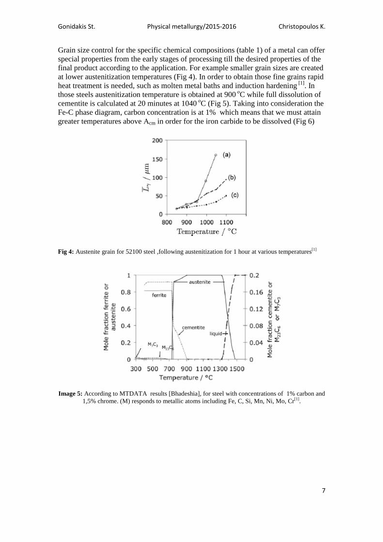
Grain size control for the specific chemical compositions (table 1) of a metal can offer
special properties from the early stages of processing till the desired properties of the
final product according to the application. For example smaller grain sizes are created
at lower austenitization temperatures (Fig 4). In order to obtain those fine grains rapid
heat treatment is needed, such as molten metal baths and induction hardening [1]
. In
those steels austenitization temperature is obtained at 900 οC while full dissolution of
cementite is calculated at 20 minutes at 1040 οC (Fig 5). Taking into consideration the
Fe-C phase diagram, carbon concentration is at 1% which means that we must attain
greater temperatures above Αcm in order for the iron carbide to be dissolved (Fig 6)
Fig 4: Austenite grain for 52100 steel ,following austenitization for 1 hour at various temperatures[1]
Image 5: According to MTDATA results [Bhadeshia], for steel with concentrations of 1% carbon and
1,5% chrome. (M) responds to metallic atoms including Fe, C, Si, Mn, Ni, Mo, Cr[1]
.
Gonidakis St. Physical metallurgy/2015-2016 Christopoulos K.
8
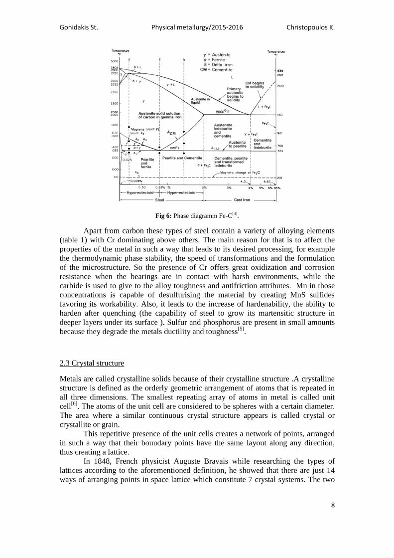
Fig 6: Phase diagramm Fe-C[4]
.
Apart from carbon these types of steel contain a variety of alloying elements
(table 1) with Cr dominating above others. The main reason for that is to affect the
properties of the metal in such a way that leads to its desired processing, for example
the thermodynamic phase stability, the speed of transformations and the formulation
of the microstructure. So the presence of Cr offers great oxidization and corrosion
resistance when the bearings are in contact with harsh environments, while the
carbide is used to give to the alloy toughness and antifriction attributes. Mn in those
concentrations is capable of desulfurising the material by creating MnS sulfides
favoring its workability. Also, it leads to the increase of hardenability, the ability to
harden after quenching (the capability of steel to grow its martensitic structure in
deeper layers under its surface ). Sulfur and phosphorus are present in small amounts
because they degrade the metals ductility and toughness[5]
.
2.3 Crystal structure
Metals are called crystalline solids because of their crystalline structure .A crystalline
structure is defined as the orderly geometric arrangement of atoms that is repeated in
all three dimensions. The smallest repeating array of atoms in metal is called unit
cell[6]
. The atoms of the unit cell are considered to be spheres with a certain diameter.
The area where a similar continuous crystal structure appears is called crystal or
crystallite or grain.
This repetitive presence of the unit cells creates a network of points, arranged
in such a way that their boundary points have the same layout along any direction,
thus creating a lattice.
In 1848, French physicist Auguste Bravais while researching the types of
lattices according to the aforementioned definition, he showed that there are just 14
ways of arranging points in space lattice which constitute 7 crystal systems. The two
Gonidakis St. Physical metallurgy/2015-2016 Christopoulos K.
9
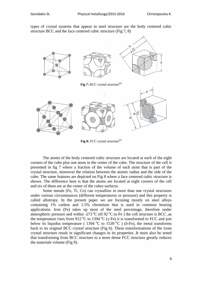
types of crystal systems that appear in steel structure are the body centered cubic
structure BCC and the face centered cubic structure (Fig 7, 8)
Fig 7: BCC crystal structure[6]
Fig 8: FCC crystal structure[6]
The atoms of the body centered cubic structure are located at each of the eight
corners of the cube plus one atom in the center of the cube. The structure of the cell is
presented in fig 7 where a fraction of the volume of each atom that is part of the
crystal structure, moreover the relation between the atomic radius and the side of the
cube. The same features are depicted on Fig 8 where a face centered cubic structure is
shown. The difference here is that the atoms are located at eight corners of the cell
and six of them are at the center of the cubes surfaces.
Some metals (Fe, Ti, Co) can crystallize in more than one crystal structures
under various circumstances (different temperatures or pressure) and this property is
called allotropy. In the present paper we are focusing mostly on steel alloys
containing 1% carbon and 1.5% chromium that is used in common bearing
applications. Iron (Fe) takes up most of the steel percentage, therefore under
atmospheric pressure and within -273 o
C till 92 o
C (a-Fe ) the cell structure is BCC ,as
the temperature rises from 912 o
C to 1394 o
C (γ-Fe) it is transformed to FCC and just
below its liquidus temperature ( 1394 o
C to 1539 o
C ) (δ-Fe), the metal transforms
back to its original BCC crystal structure (Fig 6). These transformations of the irons
crystal structure result in significant changes in its properties .It must also be noted
that transforming from BCC structure to a more dense FCC structure greatly reduces
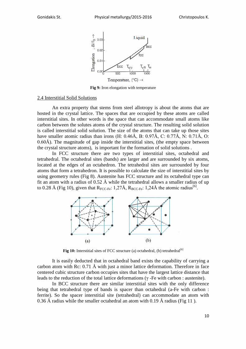
the materials volume (Fig 9).
Gonidakis St. Physical metallurgy/2015-2016 Christopoulos K.
10
Fig 9: Iron elongation with temperature
2.4 Interstitial Solid Solutions
An extra property that stems from steel allotropy is about the atoms that are
hosted in the crystal lattice. The spaces that are occupied by these atoms are called
interstitial sites. In other words is the space that can accommodate small atoms like
carbon between the solutes atoms of the crystal structure. The resulting solid solution
is called interstitial solid solution. The size of the atoms that can take up those sites
have smaller atomic radius than irons (H: 0.46Å, B: 0.97Å, C: 0.77Å, N: 0.71Å, O:
0.60Å). The magnitude of gap inside the interstitial sites, (the empty space between
the crystal structure atoms), is important for the formation of solid solutions .
In FCC structure there are two types of interstitial sites, octahedral and
tetrahedral. The octahedral sites (bands) are larger and are surrounded by six atoms,
located at the edges of an octahedron. The tetrahedral sites are surrounded by four
atoms that form a tetrahedron. It is possible to calculate the size of interstitial sites by
using geometry rules (Fig 8). Austenite has FCC structure and its octahedral type can
fit an atom with a radius of 0.52 Å while the tetrahedral allows a smaller radius of up
to 0.28 Å (Fig 10), given that RFCC-Fe: 1,27Å, RBCC-Fe: 1,24Å the atomic radius[6]
.
Fig 10: Interstitial sites of FCC structure (a) octahedral, (b) tetrahedral
[6]
It is easily deducted that in octahedral band exists the capability of carrying a
carbon atom with Rc: 0.71 Å with just a minor lattice deformation. Therefore in face
centered cubic structure carbon occupies sites that have the largest lattice distance that
leads to the reduction of the total lattice deformations (γ -Fe with carbon : austenite).
In BCC structure there are similar interstitial sites with the only difference
being that tetrahedral type of bands is spacer than octahedral (a-Fe with carbon :
ferrite). So the spacer interstitial site (tetrahedral) can accommodate an atom with
0.36 Å radius while the smaller octahedral an atom with 0.19 Å radius (Fig 11 ).

Gonidakis St. Physical metallurgy/2015-2016 Christopoulos K.
11
Fig 11: Interstitial sites of BCC structure (a) octahedral, (b) tetrahedral
[6]
Therefore creating an interstitial solid solution α-Fe with carbon is much more
difficult than in γ-Fe (FCC) and that the formation of such a solution will be
accompanied by significant lattice deformations. The interstitial site size depends on
the crystal structure atomic size.
In body centered cubic structure these interstitial sites are smaller than those in
face centered structured. As a result the FCC structure can accommodate larger atoms
in interstitial sites thus having a greater solid solubility of carbon in iron. For
example, austenite can dissolve considerably more carbon (up to 2%) than ferrite
(0.02%). The increased hardenability of steels after heat treatment is based on this
difference in solubility.
2.5 Substitutional Solid Solutions
The alloying elements that have radius size similar to iron are not able to be
dissolved into the interstitial sites, nonetheless they can be dissolved into the crystal
lattice of iron by creating substitutional solid solutions. The Hume -Rothery rules
describe solid solubility during formation of substitutional solid solutions[5]
:
1 Maximun atomic radius difference at 15%
2 Similar electronegativity
3 Same valency
4 Similar crystal structures
Substitutional solid solutions can be divided into two categories, those that are
ferrite dissolved (Ni, Cu, P and Si) and those that form carbides Mn, Cr, Mo, V, Ti, W
and Nb. In low concentrations they can also be dissolved in the ferrite matrix and in
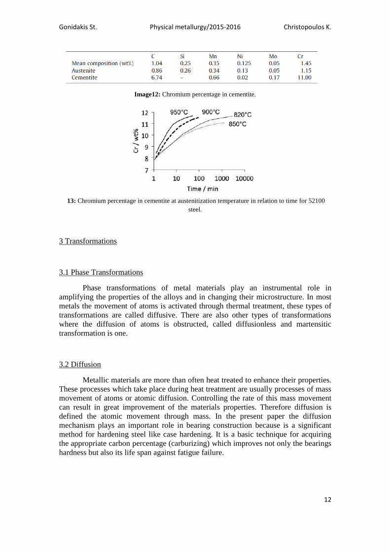
cementite. In roller bearings the basic alloying element that forms substitutional solid
solution is chromium which only comprises of 1.5 wt% of the alloy. Although
chromium is present at very low percentages it can form carbides with cementite (Fig
12, 13). Cementite thermodynamic stability is enchanced through chromium
enrichment, making its particles more tough resistant during heat treatment .This
results in an increase of the Αcm temperature (Fig 5, 6).
Gonidakis St. Physical metallurgy/2015-2016 Christopoulos K.
12
Image12: Chromium percentage in cementite.
13: Chromium percentage in cementite at austenitization temperature in relation to time for 52100
steel.
3 Transformations
3.1 Phase Transformations
Phase transformations of metal materials play an instrumental role in
amplifying the properties of the alloys and in changing their microstructure. In most
metals the movement of atoms is activated through thermal treatment, these types of
transformations are called diffusive. There are also other types of transformations
where the diffusion of atoms is obstructed, called diffusionless and martensitic
transformation is one.
3.2 Diffusion
Metallic materials are more than often heat treated to enhance their properties.
These processes which take place during heat treatment are usually processes of mass
movement of atoms or atomic diffusion. Controlling the rate of this mass movement
can result in great improvement of the materials properties. Therefore diffusion is
defined the atomic movement through mass. In the present paper the diffusion
mechanism plays an important role in bearing construction because is a significant
method for hardening steel like case hardening. It is a basic technique for acquiring
the appropriate carbon percentage (carburizing) which improves not only the bearings
hardness but also its life span against fatigue failure.

Gonidakis St. Physical metallurgy/2015-2016 Christopoulos K.
13
3.3 Diffusion coefficient
In a system where atoms are diffused in a particular manner of diffusion in a
specific crystal structure with lattice defects ,the ability of atoms to be diffused is
referred to as the diffusion rate .Temperature plays an important role to the
transformation and to the atoms diffusion speed. The diffusion coefficient of the
interstitial atoms and more specifically in carbon is and Arhenius equation[5]
:
D=D0*e–ΔG*
D/RT
D: diffusion coefficient
Do: constant characteristic to any diffusion system
ΔG*D: interstitial diffusion activation energy
R: universal gas constant
Τ: temperature
According to this equation, diffusion rate increases exponentially with an increase of
temperature .Therefore in order for carbon to make the leaps and be diffused in the
ferrite matrix, first must obtain enough energy to move to a neighboring interstitial
sites by uplifting iron atoms (Fig 14).
Fig 14: Diffusion Energy Barrier
Diffusion in lattice sites can occur when atoms of the solute move through
defects in the crystal lattice of the solvent. A necessary condition for this to happen is
that the atoms of both the solute and the solvent have similar sizes. (chromium:
166pm, iron: 156pm silicon: 111pm, nickel: 149pm, manganese :161pm,
molybdenum: 190pm)[8]
. Atoms that are diffused through steel crystal lattice (in
52100 steel ) with substitutional diffusion form a solid solution. In order for that to
happen a gap must be created from a driving force where the solvents atoms release
their bonds and be free from the near atoms. Then the free atom may leave the lattice
position leaving a hole behind (lattice walk)[5]
.Afterwards with a secondary driving
force the substitutional atom cover that hole. The sum of these energies is the
diffusion activation energy for lattice sites. It is concluded that substitutional atoms
diffusion requires smaller amounts of activation energy (Fig 15).

Gonidakis St. Physical metallurgy/2015-2016 Christopoulos K.
14
Fig 15: Diffusion coefficients
[5].
The gradients of Fig 15 depict the activation energy that is needed for the
diffusion mechanism to take place. It is observed that although carbon is more soluble
in austenite it can be diffused faster in ferrite. The reason why this is happening is
atoms in BCC structures cover more volume than atoms in FCC structures
(APFBCC=0.68, APFFCC=0.74) resulting for the former structure being spacer. It is also
to be noted that that the diffusion activation energy in lattice sites is greater (looking
at Fe on α-Fe ). Diffusion is an important process, especially of carbon in steel,
because it affects significantly the materials properties through transformations
3.4 Diffusion transformations
Recrystallization of metals is an important diffusion process in steels due to
the fact that it changes their properties. The progress of phase transformations is
described by isothermal transformation diagrams (ΤΤΤ: Time, Temperature,
Transformation). First the metal is heated and then cooled in such a way so that it
acquires the desirable properties. This process is called heat treatment which happens
at a specific temperature and time, in case of tempering and cooling speed
Isothermal transformation diagrams capture the progress of a transformation.
Specifically the curves show the start and the end of a diffusion transformation rate,
while diffusionless transformations are depicted through a straight line (Fig 16).
Gonidakis St. Physical metallurgy/2015-2016 Christopoulos K.
15
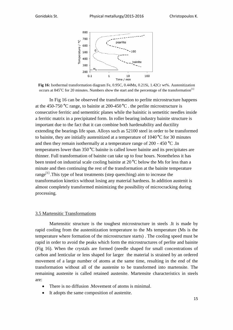
Fig 16: Isothermal transformation diagram Fe, 0.95C, 0.44Mn, 0.21Si, 1.42Cr wt%. Austenitization
occurs at 845οC for 20 minutes. Numbers show the start and the percentage of the transformation
[1]
In Fig 16 can be observed the transformation to perlite microstructure happens
at the 450-750 οC range, to bainite at 200-450
οC . the perlite microstructure is
consecutive ferritic and sementitic planes while the bainitic is semetitic needles inside
a ferritic matrix in a precipitated form. In roller bearing industry bainite structure is
important due to the fact that it can combine both hardenability and ductility
extending the bearings life span. Alloys such as 52100 steel in order to be transformed
to bainite, they are initially austenitized at a temperature of 1040 ο
C for 30 minutes
and then they remain isothermally at a temperature range of 200 - 450 οC .In
temperatures lower than 350 ο
C bainite is called lower bainite and its precipitates are
thinner. Full transformation of bainite can take up to four hours. Nonetheless it has
been tested on industrial scale cooling bainite at 20 ο
C below the Ms for less than a
minute and then continuing the rest of the transformation at the bainite temperature
range[1]
.This type of heat treatments (step quenching) aim to increase the
transformation kinetics without losing any material hardness. In addition austenit is
almost completely transformed minimizing the possibility of microcracking during
processing.
3.5 Martensitic Transformations
Martensitic structure is the toughest microstructure in steels .It is made by
rapid cooling from the austenitization temperature to the Ms temperature (Ms is the
temperature where formation of the microstructure starts) . The cooling speed must be
rapid in order to avoid the peaks which form the microstructures of perlite and bainite
(Fig 16). When the crystals are formed (needle shaped for small concentrations of
carbon and lenticular or lens shaped for larger the material is strained by an ordered
movement of a large number of atoms at the same time, resulting in the end of the
transformation without all of the austenite to be transformed into martensite. The
remaining austenite is called retained austenite. Martensite characteristics in steels
are:
There is no diffusion .Movement of atoms is minimal.
It adopts the same composition of austenite.
Gonidakis St. Physical metallurgy/2015-2016 Christopoulos K.
16
It happens in allotropic metals
There is deformation strain.
4 Roller bearing technology
There are many research papers aiming at the improvement of bearing
operations, especially enhancing the bearing life span. Factors that cause wear failure
are stress loads, temperature loads and friction where operating under harsh
environments (humidity, dust) are capable of degrading the bearing races. Therefore it
is of great importance that the metal structure is able to remain operating flawlessly
for a long time.
The characteristics of the solid structure as described above should match
characteristics like tolerance, toughness and stability. Martensitic steel transformation
has the toughest structure steel can provide, but it must somehow keep the
microstructure stable because of its brittleness. This is why after quenching steel is
heat treated again in order for the cementite to lose its carbon atom surplus. It has
been studied that tempering at temperatures just above Ms for almost an hour
followed by cooling at room temperature forms a partial bainite structure and the
remained austenite transforms into martensite, leading to a strong structure that is
satisfactory for roller element bearings [1]
. Another example is the fine austenite grain
structure which is formed firstly by heating at temperatures of 1150 ο
C, quenching in
heated oil at 150 οC and cooling at room temperature, following austenitization at
900 οC and finally tempering at 250
οC
[1]. According to Hong -Seok Yang's paper
about correlating temperature when martensitic transformation starts and austenite
grains size, the Ms temperature is greater when the grains are more refined.
4.1 Low concentration of alloying elements steels[2]
Stainless steel with small percentages of alloying elements that range from
2,07 % and chromium of at least 10% are another type of ferrous material that have
superior mechanical properties to regular steels. The aim is to increase hardness after
heat treatment.
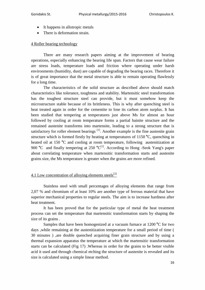
It has been proved that for the particular type of metal the heat treatment
process can set the temperature that martensitic transformation starts by shaping the
size of its grains .
Samples that have been homogenized at a vacuum furnace at 1200 ο
C for two
days ,while remaining at the austenitization temperature for a small period of time (
30 minutes ) ,are double quenched acquiring finer grain structure and by using a
thermal expansion apparatus the temperature at which the martensitic transformation
starts can be calculated (Fig 17) .Whereas in order for the grains to be better visible
acid it used and through chemical etching the structure of austenite is revealed and its
size is calculated using a simple linear method.
Gonidakis St. Physical metallurgy/2015-2016 Christopoulos K.
17
Fig 17: Lγ refined austenite grain, M
os-Ms the fraction of martensite, quantitative
estimates of the dependence of the observed MS on the austenite grain size
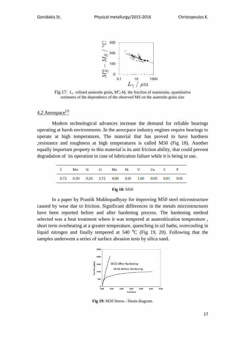
4.2 Aerospace[3]
Modern technological advances increase the demand for reliable bearings
operating at harsh environments .In the aerocpace industry engines require bearings to
operate at high temperatures. The material that has proved to have hardness
,resistance and toughness at high temperatures is called M50 (Fig 18). Another
equally important property to this material is its anti friction ability, that could prevent
degradation of its operation in case of lubrication failure while it is being in use.
Fig 18: Μ50
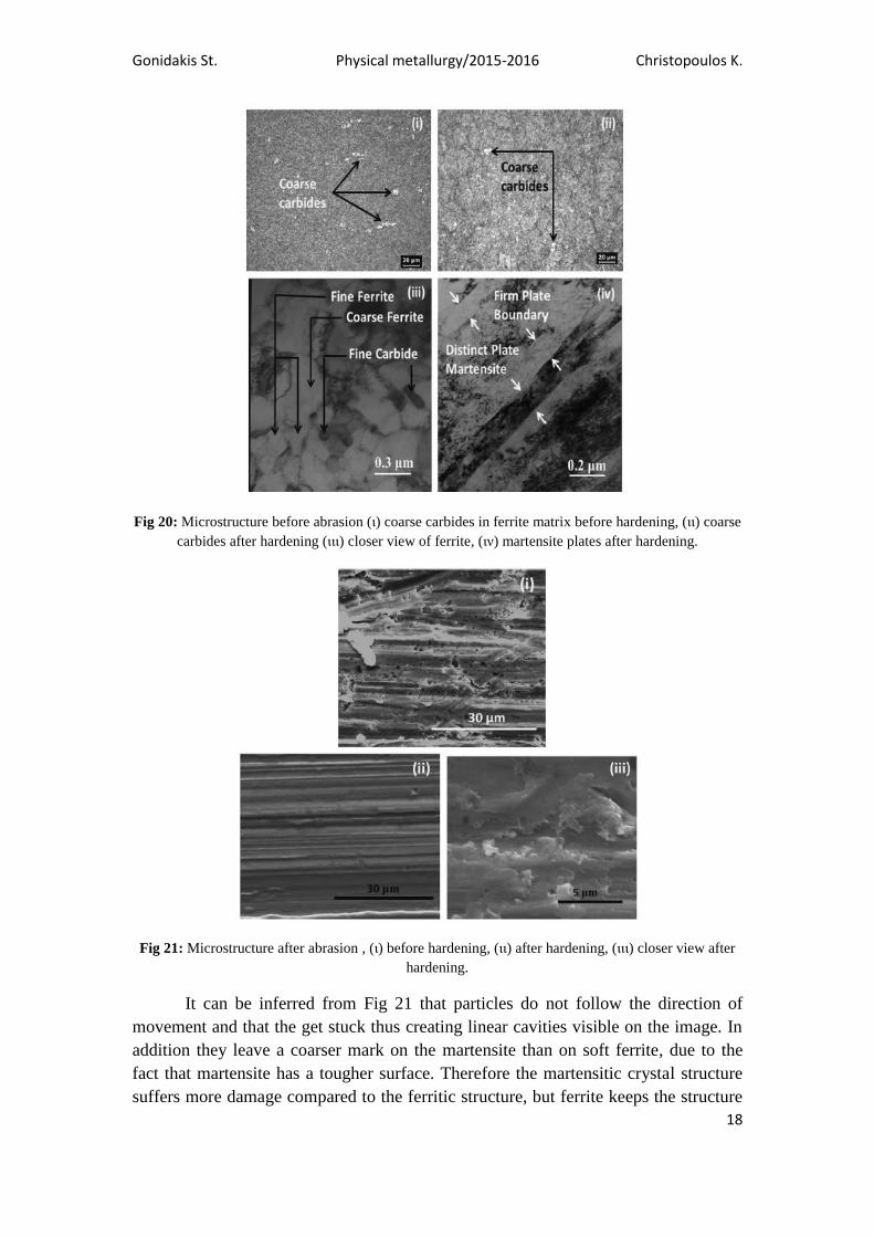
In a paper by Prantik Mukhopadhyay for improving M50 steel microstructure
caused by wear due to friction. Significant differences in the metals microstructures
have been reported before and after hardening process. The hardening method
selected was a heat treatment where it was tempered at austenitization temperature ,
short term overheating at a greater temperature, quenching in oil baths, overcooling in
liquid nitrogen and finally tempered at 540 οC (Fig 19, 20). Following that the
samples underwent a series of surface abrasion tests by silica sand.
Fig 19: M50 Stress - Strain diagram.
Gonidakis St. Physical metallurgy/2015-2016 Christopoulos K.
18
Fig 20: Microstructure before abrasion (ι) coarse carbides in ferrite matrix before hardening, (ιι) coarse
carbides after hardening (ιιι) closer view of ferrite, (ιν) martensite plates after hardening.
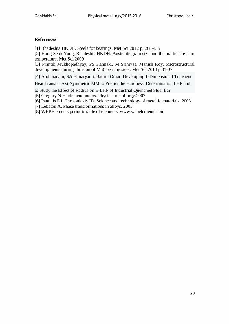
Fig 21: Microstructure after abrasion , (ι) before hardening, (ιι) after hardening, (ιιι) closer view after
hardening.
It can be inferred from Fig 21 that particles do not follow the direction of
movement and that the get stuck thus creating linear cavities visible on the image. In
addition they leave a coarser mark on the martensite than on soft ferrite, due to the
fact that martensite has a tougher surface. Therefore the martensitic crystal structure
suffers more damage compared to the ferritic structure, but ferrite keeps the structure

Gonidakis St. Physical metallurgy/2015-2016 Christopoulos K.
19
stable during martensitic recrystallization. The deformation during abrasion has many
features. First occurs plastic deformation while the surface of the races is being
etched. The martensite creates dislocation in the crystal structure while ferrite being
ductile recovers from the deformation, occurring in lasting longer (the material)
Conclusion
The purpose of this paper is to comprise steel through bearings. As it is being
presented the right combination of iron and alloy elements can provide many versatile
products that can aid sciences evolution. The reader has the opportunity to understand
the transformations occurring inside the material in a magnified perspective using
some examples from other papers. The paper can not cover all the metallurgy science
from bearings but a fraction of it.
Gonidakis St. Physical metallurgy/2015-2016 Christopoulos K.
20
References
[1] Bhadeshia HKDH. Steels for bearings. Met Sci 2012 p. 268-435
[2] Hong-Seok Yang, Bhadeshia HKDH. Austenite grain size and the martensite-start
temperature. Met Sci 2009
[3] Prantik Mukhopadhyay, PS Kannaki, M Srinivas, Manish Roy. Microstructural
developments during abrasion of M50 bearing steel. Met Sci 2014 p.31-37
[4] Abdlmanam, SA Elmaryami, Badrul Omar. Developing 1-Dimensional Transient
Heat Transfer Axi-Symmetric MM to Predict the Hardness, Determination LHP and
to Study the Effect of Radius on E-LHP of Industrial Quenched Steel Bar.
[5] Gregory N Haidemenopoulos. Physical metallurgy.2007
[6] Pantelis DJ, Chrisoulakis JD. Science and technology of metallic materials. 2003
[7] Lekatou A. Phase transformations in alloys. 2005
[8] WEBElements periodic table of elements. www.webelements.com