steel roof truss optimization
TRANSCRIPT
8/9/2019 Steel Roof Truss Optimization
http://slidepdf.com/reader/full/steel-roof-truss-optimization 1/98
INFORMATION TO USERS
This manuscript has been reproduced from the microfilm master. UMI films the text directly from the original or copy submitted. Thus, some
thesis and dissertation copies are in typewriter face, while others may be
from any type o f computer printer.
The quality of this reproduction is dependent upon the quality of the
copy submitted. Broken or indistinct print, colored or poor quality
illustrations and photographs, print bleedthrough, substandard margins,
and improper alignment can adversely affect reproduction.
In the unlikely event that the author did not send UMI a complete
manuscript and there are missing pages, these will be noted. Also, if
unauthorized copyright material had to be removed, a note will indicate
the deletion.
Oversize materials (e.g., maps, drawings, charts) are reproduced by
sectioning the original, beginning at the upper left-hand comer and
continuing from left to right in equal sections with small overlaps. Each
original is also photographed in one exposure and is included in reduced
form at the back o f the book.
Photographs included in the original manuscript have been reproduced
xerographically in this copy. Higher quality 6” x 9” black and white
photographic prints are available for any photographs or illustrations
appearing in this copy for an additional charge. Contact UMI directly to
order.
UMIA Bell & Howell Information Company
300 North Zeefo Road, Ann Arbor MI 48106-1346 USA
313/761-4700 800/S21-0600
pro du ced with perm ission of the copyright owner. Further reproduction prohibited without permission .
8/9/2019 Steel Roof Truss Optimization
http://slidepdf.com/reader/full/steel-roof-truss-optimization 2/98roduced with permission of the copyright owner. Further reproduction prohibited without permission.
8/9/2019 Steel Roof Truss Optimization
http://slidepdf.com/reader/full/steel-roof-truss-optimization 3/98
STEEL ROOF TRUSS OPTIMIZATION
by
Min Shuai
A Thesis Presented to the
FACULTY OF THE SCHOOL OF ARCHITECTURE
UNIVERSITY OF SOUTHERN CALIFORNIA
In Partial Fulfillment of the
Requirements for the Degree
MASTER OF BUILDING SCIENCE
(Architecture)
May 1998
Copyright 1998 Min Shuai
ep rodu ced with perm ission o f the copyright owner. Further reproduction prohibited without permission .
8/9/2019 Steel Roof Truss Optimization
http://slidepdf.com/reader/full/steel-roof-truss-optimization 4/98
UMI Number: 1391099
UMI Microform 1391099 Copyright 1998, by UMI Company. All rights reserved.
This microform edition is protected against unauthorized
copying under Title 17, United States Code.
UMI300 North Zeeb Road
Ann Arbor, MI 48103
prod uced with perm ission of the copyright owner. Further reproduction prohibited without permission.
8/9/2019 Steel Roof Truss Optimization
http://slidepdf.com/reader/full/steel-roof-truss-optimization 5/98
UNIVERSITY OF SOUTHERN CALIFORNIA
SCHOOL OF ARCHITECTURE
UNIVERSITY PARK
LOS ANGELES, CA 90089-0291
This thesis, written 6y J Min Shuai
under the direction o f h er ____ Thesis Committee,
andapproved 6y off its members, has 6een presented
to and accepted 6y the (Dean o f The SchooC o f
Architecture in partiaCfuCfiKment of the requirements
fo r the degree of
MASTER- OF BUILDING SCIENCE
K[. ~
(Dean
(Date.3 O ^ 3
T H E S I S C O M M I T T E E
\ L \ U
rodu ced with perm ission o f the copyright owner. Further reproduction prohibited without permission.
8/9/2019 Steel Roof Truss Optimization
http://slidepdf.com/reader/full/steel-roof-truss-optimization 6/98
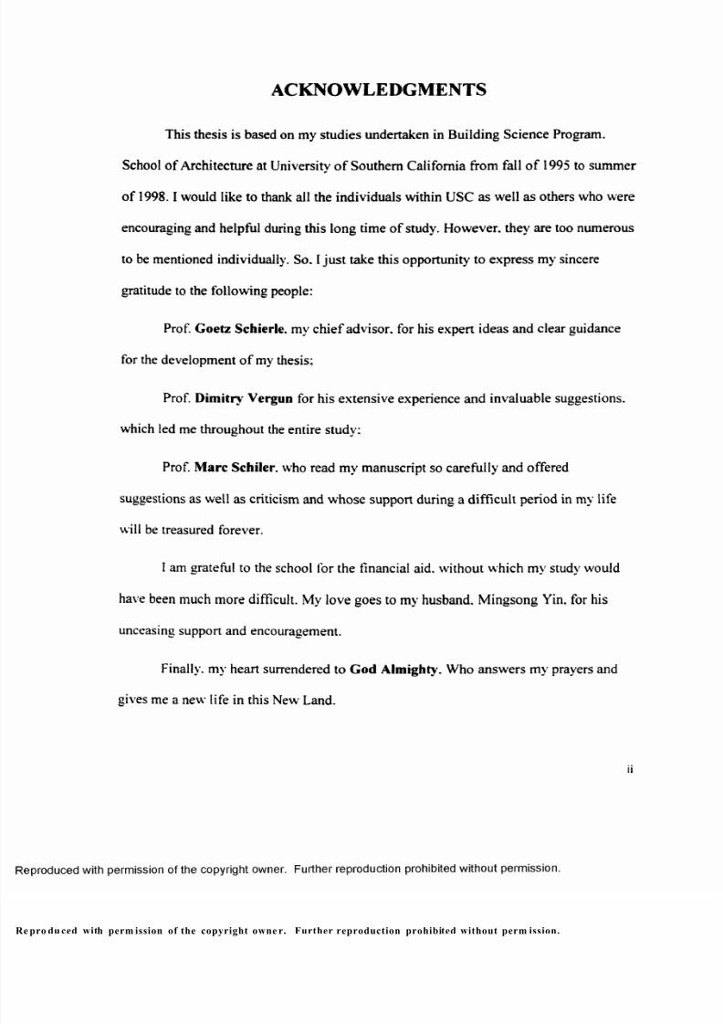
ACKNOWLEDGMENTS
This thesis is based on my studies undertaken in Building Science Program.
School of Architecture at University of Southern California from fall of 1995 to summer
of 1998.1would like to thank all the individuals within USC as well as others who were
encouraging and helpful during this long time of study. However, they are too numerous
to be mentioned individually. So. I just take this opportunity to express my sincere
gratitude to the following people:
Prof. Goetz Schierle. my chief advisor, for his expert ideas and clear guidance
for the development o f my thesis;
Prof. Dimitry Vergun for his extensive experience and invaluable suggestions,
which led me throughout the entire study;
Prof. Marc Schiler. who read my manuscript so carefully and offered
suggestions as well as criticism and whose support during a difficult period in my life
will be treasured forever.
I am grateful to the school for the financial aid. without which my study would
have been much more difficult. My love goes to my husband. Mingsong Yin, for his
unceasing support and encouragement.
Finally, my heart surrendered to God Almighty. Who answers my prayers and
gives me a new life in this New Land.
ii
pro du ced with perm ission of the copyright owne r. Further reproduction prohibited without perm ission.
8/9/2019 Steel Roof Truss Optimization
http://slidepdf.com/reader/full/steel-roof-truss-optimization 7/98
Table of Contents
Acknowledgments
List o f Figures
List of Charts
I. Objective of Roof Truss Study
II. Basic Concepts of Trusses
1. From Beam to Truss - Definition o f Trusses
2. Loads on Trusses
3. Stability and Determinacy
4. Common Types o f Ro of Trusses
5. Materials for Trusses
6. Construction Concern: Joint
III. Comparative Truss Analysis by Computer
1. Computer Program: MultiFrame
2. Prototypes of Trusses to be Studied
3. Simulation Assumptions
4. Static Loads
5. Comparing Self-Weight o f Trusses of Different
Configurations
5.1. Design of Steel Compressive Members
5.2. Design of Steel Tensile Members
e pro duc ed with permissio n of the copyright own er. Further reproduction prohibited without permissio n.
8/9/2019 Steel Roof Truss Optimization
http://slidepdf.com/reader/full/steel-roof-truss-optimization 8/98
5.3. Comparison o f Truss Self-Weight and Deflection 28
5.4. Conclusions 33
6. Comparing TS Construction with the WT&DL 34
6.1. Design of TS Trusses 35
6.2. Comparing with the WT&DL Construction 38
6.3. Conclusions 40
7. Comparing Combined Stresses with Axial Stresses for
200ft-Span Cases 42
7.1. Design for Combined Stresses 42
7.2. Comparison and Conclusions 46
8. Comparing Different H/L Ratios for 200ft-Span Cases 47
8.1. R atiosof 1/5. 1/8. 1/10. 1/12.5 and 1/15 47
8.2. Comparison and Conclusions 53
9. Comparing Different Panel Sizes for 200ft-Span Cases 56
9.1. Panel Sizes o f L/4. L/6. L/8. L/10 and L/12 56
9.2. Comparison and Conclusions 62
IV. Conclusions and Recommendations 65
Appendix Design o f Trusses 67
Reference 87
iv
pro du ced with perm ission of the copyright owner. Further reproduction prohibited without permission .
8/9/2019 Steel Roof Truss Optimization
http://slidepdf.com/reader/full/steel-roof-truss-optimization 9/98
List of Figures
Figure 2-1 A Simple Beam j
Figure 2-2 A Simple Spanning Truss j
Figure 2-3 Genesis of the Truss from the Beam 4
Figure 2-4 Elements o f a Planar Truss 6
Figure 2-5 Typical R oof Truss Profiles 9
Figure 2-6 Basic Truss Patterns 10
Figure 2-7 Typical Steel Trusses 12
Figure 2-8
%Arrangement o f Truss Joints 13
Figure 3-1 Prototypes o f Trusses to be Studied 15
Figure 3-2 Overall Study Schedule 17
Figure 3-3 Roof Truss Arrangement 17
Figure 3-4 Critical Bars at Quick Design 20
Figure 3-5 Internal Axial Force Diagrams of 200-ft Span Trusses 24
Figure 3-6 Trusses of Combined Stresses 43
Figure 3-7 Trusses at Different H/L Ratios 48-52
Figure 3-8 Trusses of Different Panel Sizes 57-61
p rodu ced with permission of the copyright owner. Further reproduction prohibited without permission.
8/9/2019 Steel Roof Truss Optimization
http://slidepdf.com/reader/full/steel-roof-truss-optimization 10/98
List of Charts
Chart 3-1 Truss Weight Assumption 22
Chart 3-2 Comparison of Self-Weights of Trusses @ Different Spans 29
Chart 3-3 Comparison o f Truss Weights with Assumptions 31
Chart 3-4 Comparison o f Top/Bottom Chords with Web Members 31
Chart 3-5 Truss Deflection 32
Chart 3-6 Comparison of Self-Weights of Tube Trusses @ Different Spans 39
Chart 3-7 Comparison of TB Trusses with WT&DL Trusses 41
Chart 3-8 Comparison of Top/Bottom Chords with Web Members 41
Chart 3-9 Comparison o f Trusses Loaded Differently 46
Chart 3-10 Comparison of Self-Weights of Trusses @ Different H/L Ratios 54-55
Chart 3-11 Comparison of Self-Weights of Trusses o f Different Panel Sizes 63 -64
V I
p rodu ced with p ermission of the copyright owner. Further reproduction prohibited without permission.
8/9/2019 Steel Roof Truss Optimization
http://slidepdf.com/reader/full/steel-roof-truss-optimization 11/98
I . O bjective o f R oof Tru ss Study
Trusses have been used extensively for roof structure of many spans. Truss
configuration has a significant impact on both a building’s exterior appearance and
interior space.
However, in current practice, there is a lack of guidelines for optimum truss
design for architects and engineers. The usual design routine is that architects first
design, o r even jus t draw , a truss profile and pattern for some sort o f architectural
concerns without enough structural knowiedge. The design is then given to structural
engineers to calculate without regard of optimum, because of time and profit concerns.
As a result, the most efficient design is seldom achieved.
The objective o f this study is to set up a guideline for preliminary design. The
study is to compare the self-weight o f steel roof trusses of different configurations at
different spans. Constructions of Tee & double angle (WT&DL) and tube (TS) trusses
are compared. Different loading conditions, height-to-span ratio and panel size have
also been studied to see how they affect the design of roof trusses.
Basic concepts o f trusses need to be reviewed first.
pro du ced with perm ission of the copyright owner. Further reproduction prohibited without perm ission.
8/9/2019 Steel Roof Truss Optimization
http://slidepdf.com/reader/full/steel-roof-truss-optimization 12/98
II. Basic Concepts of Trusses
1. From Beam to Truss—D efinition o f Tru sses
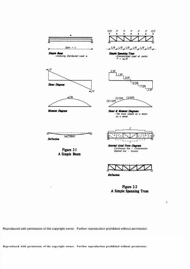
1.1. What is a Beam?
A beam is a linear structural elem ent that is primarily subjected to transverse
loading. Bending and shear stresses are developed to resist loads. Figure 2-1 are shear-
and bending- diagrams o f a simply supported beam with a uniformly distributed load vt
along its span. As shown in the graph, the stresses are not evenly distributed along the
span of the beam, and the deflection o f the beam increases with the 4th power of its
span under uniform load. Certainly, the beam will collapse under its own weight when
its span goes beyond a certain limit.
1.2. What is a Truss?
A truss is a framework of triangular formation of linear elements. Just like a
beam, a s imple spanning truss carries superimposed loads to its supports. However,
because inefficient stresses such as bending and shear are eliminated and only
compression and tension are developed in its members to resist loads, a truss is more
efficient than an equivalent beam earn ing the same load over an equal span (Figure 2-
2 ).
pro du ced with perm ission of the copyright owne r. Further reproduction prohibited without permission .
8/9/2019 Steel Roof Truss Optimization
http://slidepdf.com/reader/full/steel-roof-truss-optimization 13/98
Sp an = L
Simple Beam-Uniformly Distributed Load: w
, L / 6 , L / 6 , 1 / 6 , L / 6 t L / 6 , L / 6 f
Simple Spuming Tim-Concentrated Load at Joints:
P = wL/6
wL/2
Shear Ditgnm
wL/2
*L’ / 8
Moment Ditgnm
2.5P
I I.5P
I 0.5P
^OlP |
-2.5P
(2/3)PL_S ^)E L( 5 / t 2 ) P L ^ > '
Shear St Moment Diagrams-The truss viewed os o beam
as a whole
Deflection5 w L'/38 4E !
F ig u re MA Simple Beam
' n J
Tv h x J N s
s s s
l 'h
Internal Axial Force DiagramContinuous line - Compression
Dashed line - Tension
Deflection
Figure 2-2A S im ple S pann ing Truss
rod uced with permission of the copyright owner. Further reproduction prohibited without permission .
8/9/2019 Steel Roof Truss Optimization
http://slidepdf.com/reader/full/steel-roof-truss-optimization 14/98
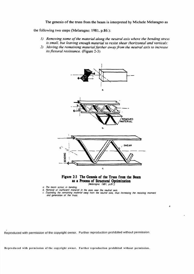
The genesis o f the truss from the beam is interpreted by Michele Melaragno as
the following two steps (Melaragno: 1981. p.86.):
1) Removing some o f the material along the neutral axis where the bending stress
is small, but leaving enough material to resist shear (horizontal and vertical):
2) Moving the remaining material farther aw ay from the neutral axis to increase
its flexu ral resistance. (Figure 2-3)
a.
/REMOVEDMATERIAL
b.
SHEAR
c.
Fi gu re 2-3 The Ge nes is o f the T russ f rom t he
as a Proces ~ t imiza t ion(Meioragno: w u i. p .ts/.
Beam
a. The beam action in bending.
b. Removal of inefficient material in the 2one near the neutral axis.
c. Expanding the remaining m aterial away from the neutral axis, thu s increasing
and generation of t he truss.the resisting moment
4
pro du ced with perm ission of the copyright owner. Further reproduction prohibited without permission .
8/9/2019 Steel Roof Truss Optimization
http://slidepdf.com/reader/full/steel-roof-truss-optimization 15/98
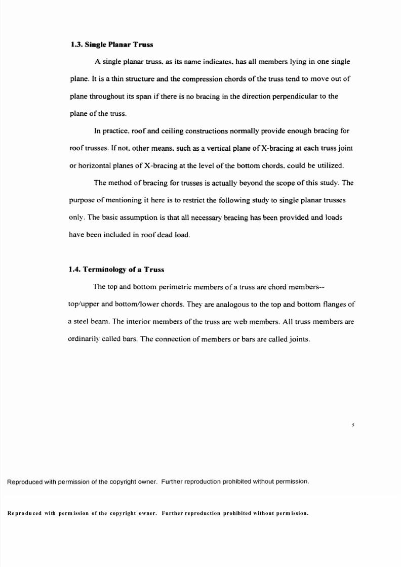
1.3. Single Planar Truss
A single planar truss, as its name indicates, has all members lying in one single
plane. It is a thin structure and the compression chords of the truss tend to move out of
plane throughout its span if there is no bracing in the direction perpendicular to the
plane o f the truss.
In practice, roof and ceiling constructions normally provide enough bracing for
roof trusses. If not. other means, such as a vertical plane o f X-bracing at each truss joint
or horizontal planes of X-bracing at the level of the bottom chords, could be utilized.
The method of bracing for trusses is actually beyond the scope o f this study. The
purpose of mentioning it here is to restrict the following study to single planar trusses
only. The basic assumption is that all necessary bracing has been provided and loads
have been included in roof dead load.
1.4. Terminology of a Truss
The top and bottom perimetric members of a truss are chord members--
top/upper and bottom/lower chords. They are analogous to the top and bottom flanges of
a steel beam. The interior members of the truss are web members. All truss members are
ordinarily called bars. The connection of members or bars are called joints.
pro du ced with perm ission of the copyright owner. Further reproduction prohibited without perm ission.
8/9/2019 Steel Roof Truss Optimization
http://slidepdf.com/reader/full/steel-roof-truss-optimization 16/98
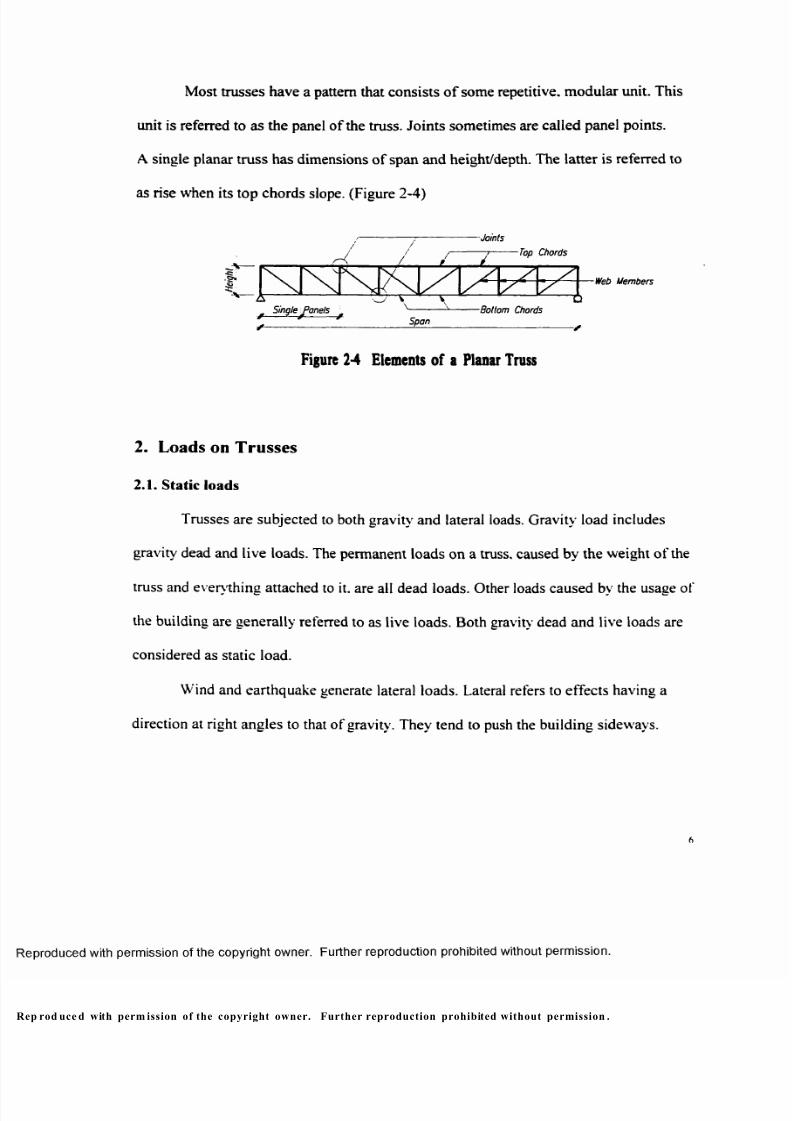
Most trusses have a pattern that consists of some repetitive, modular unit. This
unit is referred to as the panel of the truss. Join ts sometimes are called panel points.
A single planar truss has dimensions of span and height/depth. The latter is referred to
as rise when its top chords slope. (Figure 2-4)
-Joints
Top Chords
Web Members
Bottom Chords
Span
Figure 2-4 Elemen ts o f a Planar Truss
2. Loads on T russes
2.1. Static loads
Trusses are subjected to both gravity and lateral loads. Gravity load includes
gravity dead and live loads. The permanent loads on a truss, caused by the weight of the
truss and everything attached to it. are all dead loads. Other loads caused by the usage of
the building are generally referred to as live loads. Both gravity dead and live loads are
considered as static load.
Wind and earthquake generate lateral loads. Lateral refers to effects having a
direction at right angles to that of gravity. They tend to push the building sideways.
p rod uce d with perm ission of the copyright owner. Further reproduction prohibited without permission .
8/9/2019 Steel Roof Truss Optimization
http://slidepdf.com/reader/full/steel-roof-truss-optimization 17/98
Although wind load and earthquake load have dynamic effects on buildings, they
are normally treated as equivalent static loads in building structure design. Lateral loads
are not considered in this study.
2.2. Secondary stress
The ideal assumption is that loads are applied to truss joints, so the members are
loaded only through the joints and only direct compression or tension forces are
generated in truss members.
Since the truss weight is actually distributed along the bar span, the above
assumption is never exactly true. The small flexural stress in a real truss is called
secondary stress. Since for short to medium span trusses, the truss weight ordinarily is
not a major part o f the total design load, the usual practice is to consider units of weight
as collected at the truss joints.
Live load can be applied to the truss joints through joists. However, if roof decks
are supported by the top chords directly or ceiling load is continuously distributed along
the bottom chords, the chords are loaded with a linear uniform load and function as
beams between their end joints. Secondary stress is therefore generated. In such cases,
truss chords need to be designed for the combined effects o f the axial stress caused by
the truss action and the bending stress caused by the direct loading. One study will
compare the combined stress cases with joint loaded cases.
rod uced with permission of the copyright owner. Further reproduction prohibited without permission.
8/9/2019 Steel Roof Truss Optimization
http://slidepdf.com/reader/full/steel-roof-truss-optimization 18/98
3. Stab ility and D eterm inacy
Before a given truss is analyzed, its stability and determinacy need to be
determined. When a structure can not satisfy static equilibrium, it is unstable, and
therefore unacceptable. If a structure has the minimum number of members and
supports required for its equilibrium, it is called statically determinate. A statically
determinate structure can be analyzed by means of statics alone. If a structure has more
than the necessary members and/or supports (over stabilized), it is called statically
indeterminate. A statically indeterminate structure cannot be analyzed by means of
statics, but requires also the theory of elasticity.
According to its definition, the generation of a truss from single elements can be
viewed as two steps: 1) Connection o f three bars to form a base triangle, that means
three initial bars with three initial joints: 2) More triangles are added to the first one.
that is. two bars for each additional joint. So. the total number of truss members m is
equal to the initial 3 bars of the base triangle, plus 2 members for each additional joint
{f-3):
m=3~2(j-3)=2j-3
Obviously, if m<2j-3. uhich means not enough bars, the truss is unstable. If
m>2j-3. which means there are more bars than needed, the truss is indeterminate. Only
if m=2j-3. which means enough and necessary bars are provided, is a truss internally
stable and determinate. Another effect factor is the arrangement o f bars. They have to
p rodu ced with perm ission of the copyright owner. Further reproduction prohibited without permission.
8/9/2019 Steel Roof Truss Optimization
http://slidepdf.com/reader/full/steel-roof-truss-optimization 19/98
form triangles. If there are polygons, other than triangles, existing in the truss, the truss
would have “geometric instability.”
The support conditions can also affect the external s tability and determinacy of a
truss. Since the planar truss to be discussed in this study functions as a simple beam in
terms of supports, the external stability and determinacy are assumed as for beams.
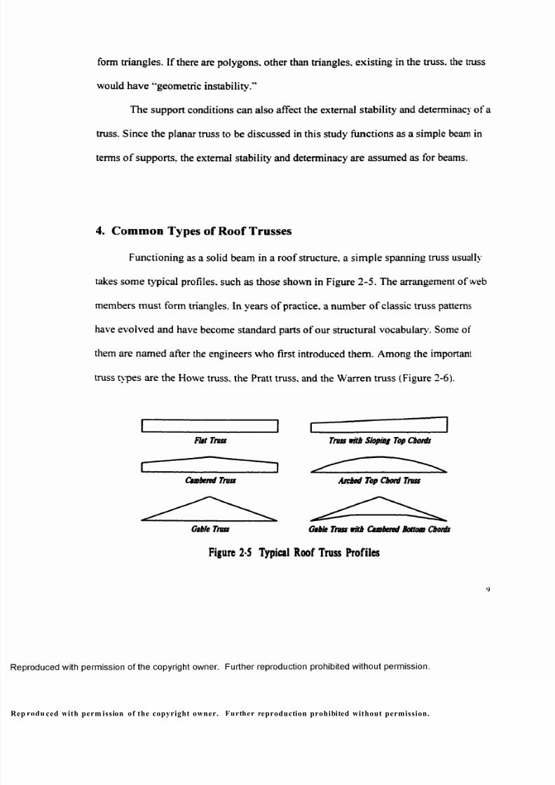
4. Com m on Types o f R oof Trusses
Functioning as a solid beam in a roof structure, a sim ple spanning truss usually
takes some typical profiles, such as those shown in Figure 2-5. The arrangement of web
members must form triangles. In years o f practice, a number o f classic truss patterns
have evolved and have become standard parts of our structural vocabulary'. Some of
them are named after the engineers who first introduced them. Among the important
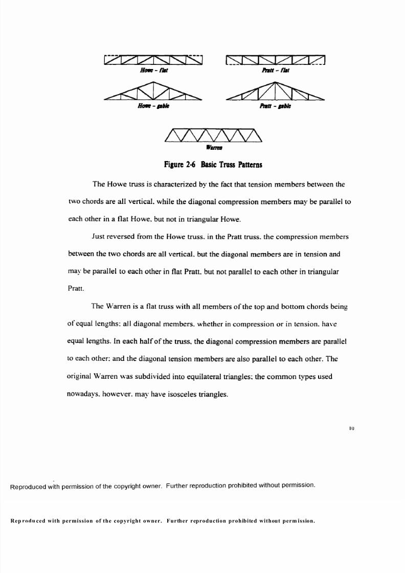
truss types are the Howe truss, the Pratt truss, and the Warren truss (Figure 2-6).
Flit Truss Truss with Sloping Top Chords
u . _____________ i ^ — _____________
Cumbered Truss Arched Top Chord Truss
Gtble Truss Gsble Truss with Cambered Bottom Chords
Figure 2-5 Typica l Ro of Truss Pro f i les
9
p rodu ced with perm ission of the copyright owner. Further reproduction prohibited without permission.
8/9/2019 Steel Roof Truss Optimization
http://slidepdf.com/reader/full/steel-roof-truss-optimization 20/98
m zi
Howt- gtbk Pntt - gtble
AAAAAAWilTU
Figu re 2-6 Basic Truss Pat terns
The Howe truss is characterized by the fact that tension members between the
two chords are all vertical, while the diagonal compression members may be parallel to
each other in a flat Howe, but not in triangular Howe.
Just reversed from the Howe truss, in the Pratt truss, the compression members
between the two chords are all vertical, but the diagonal members are in tension and
may be parallel to each other in flat Pratt, but not parallel to each other in triangular
Pratt.
The Warren is a flat truss with all members of the top and bottom chords being
of equal lengths: all diagonal members, whether in compression or in tension, have
equal lengths. In each half of the truss, the diagonal compression members are parallel
to each other: and the diagonal tension members are also parallel to each other. The
original Warren was subdivided into equilateral triangles: the common types used
nowadays, however, may have isosceles triangles.
10
p rodu ced with permission of the copyright owner. Further reproduction prohibited without perm ission.
8/9/2019 Steel Roof Truss Optimization
http://slidepdf.com/reader/full/steel-roof-truss-optimization 21/98
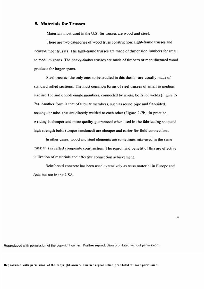
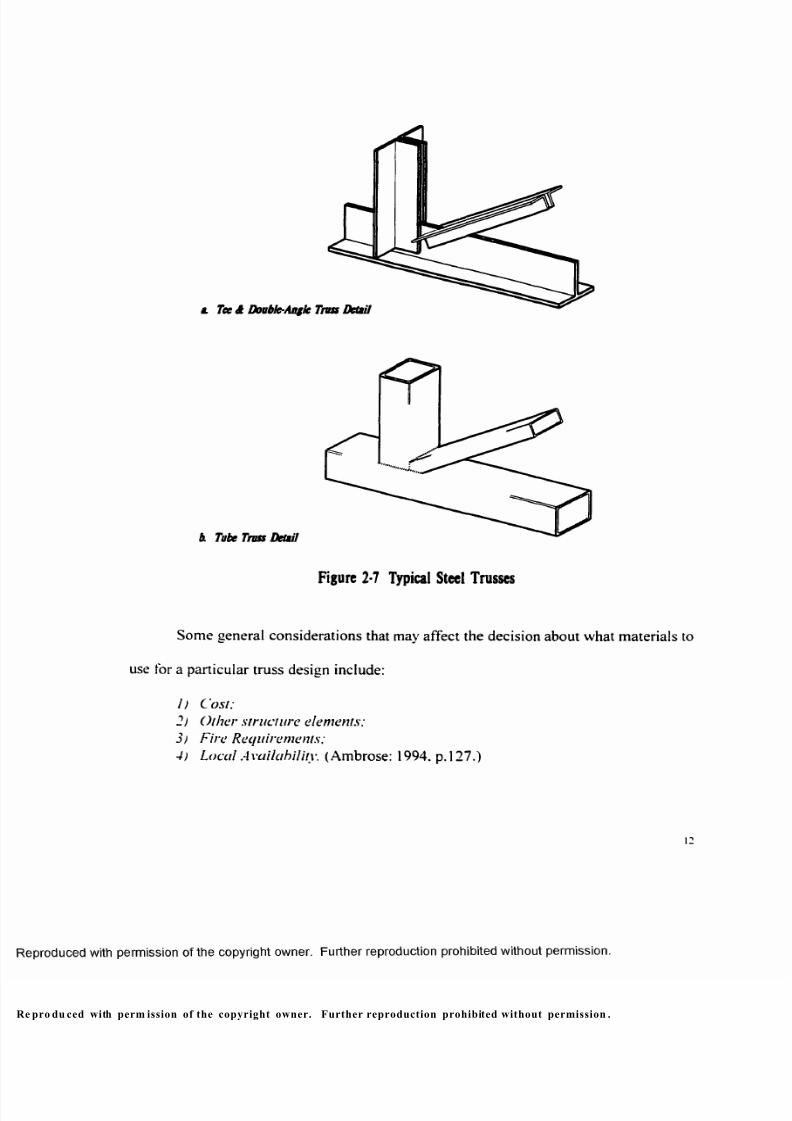
§. M aterials for T russes
Materials most used in the U.S. for trusses are wood and steel.
There are two categories of wood truss construction: light-frame trusses and
heavy-timber trusses. The light-frame trusses are made o f dimension lumbers for small
to medium spans. The heavy-timber trusses are made of timbers or manufactured wood
products for larger spans.
Steel trusses—the only ones to be studied in this thesis—are usually made of
standard rolled sections. The most common forms of steel trusses of small to medium
size are Tee and double-angle members, connected by rivets, bolts, or welds (Figure 2-
7a). Another form is that o f tubular members, such as round pipe and flat-sided,
rectangular tube, that are directly welded to each other (Figure 2-7b). In practice,
welding is cheaper and more quality-guaranteed when used in the fabricating shop and
high strength bolts (torque tensioned) are cheaper and easier for field connections.
In other cases, wood and steel elements are sometimes mix-used in the same
truss: this is called composite construction. The reason and benefit of this are effective
utilization of materials and effective connection achievement.
Reinforced concrete has been used extensively as truss material in Europe and
Asia but not in the USA.
p rod uced with permission of the copyright owner. Further reproduction prohibited without permission .
8/9/2019 Steel Roof Truss Optimization
http://slidepdf.com/reader/full/steel-roof-truss-optimization 22/98
a. Teed Double-Angle Truss Detail
& Tube Truss Detail
Figure 2-7 Typical Steel Trusses
Some general considerations that may affect the decision about what materials to
use for a particular truss design include:
1) Cost;
2) Other structure elements;
3/ Fire Requirements;4) Local Availability. (Ambrose: 1994. p. 127.)
pro du ced with perm ission of the copyright owner. Further reproduction prohibited without permission .
8/9/2019 Steel Roof Truss Optimization
http://slidepdf.com/reader/full/steel-roof-truss-optimization 23/98
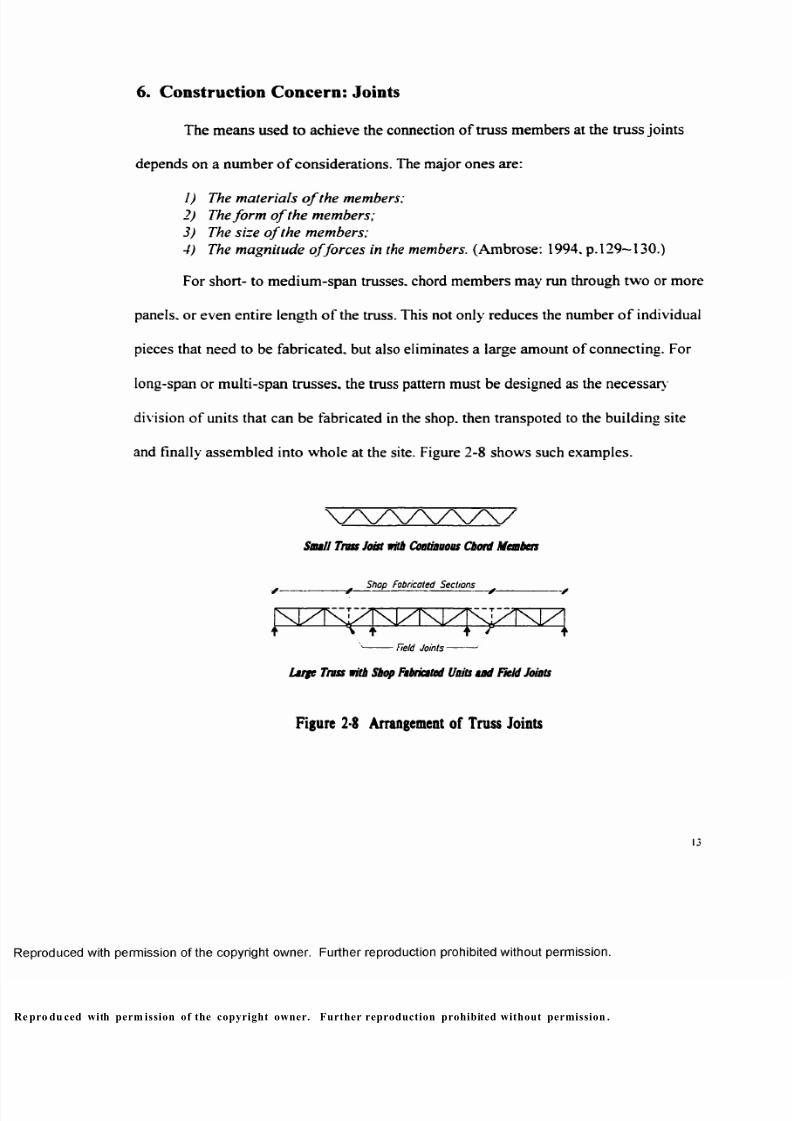
6. Construction Concern: Joints
The means used to achieve the connection of truss members at the truss joints
depends on a number o f considerations. The major ones are:
1) The materials o f the members;
2) The for m o f the members;
3) The size o f the members;
4) The magnitude o f forces in the members. (Ambrose: 1994. p. 129—130.)
For short- to medium-span trusses, chord members may run through two or more
panels, or even entire length o f the truss. This not only reduces the number o f individual
pieces that need to be fabricated, but also eliminates a large amount o f connecting. For
long-span or multi-span trusses, the truss pattern must be designed as the necessary
division of units that can be fabricated in the shop, then transpoted to the building site
and finally assembled into whole at the site. Figure 2-8 shows such examples.
Small Truss Joist with Continuous Chord Members
____________ Shop Fabricated Sections ____________
' Field Jo int s----------
Large Truss with Shop Fabricated Units and Reid Joints
Fi gu re 2 -8 Ar ra nge me nt o f T russ Jo in t s
pro du ced with perm ission of the copyright owner. Further reproduction prohibited without permission .
8/9/2019 Steel Roof Truss Optimization
http://slidepdf.com/reader/full/steel-roof-truss-optimization 24/98
III. Comparative Truss Analyses by Computer
1. C om puter Program: M ultiFram e
MultiFrame is a structural analysis and design program for Windows 95 and
Windows NT released by Formation Design Systems Pty Ltd. ''MultiFrame" and
"Section Maker" are two of several parts of the program, which are used in this study. In
MultiFrame. a structure can be first established in a ‘‘Frame” window, and load can then
be applied on the structure in a "Load” window. After analyzing, a "Plo t” window
shows results graphically and a "Result" window shows numerical results. In Section
Maker, after a section is designed/drawn and material is assigned, the properties of the
section are computed by the program automatically. However, since functions such as
editing, formatting and plotting are not yet implemented, the working process is actually
not as easy as it sounds. All the information needed can only be read from screen.
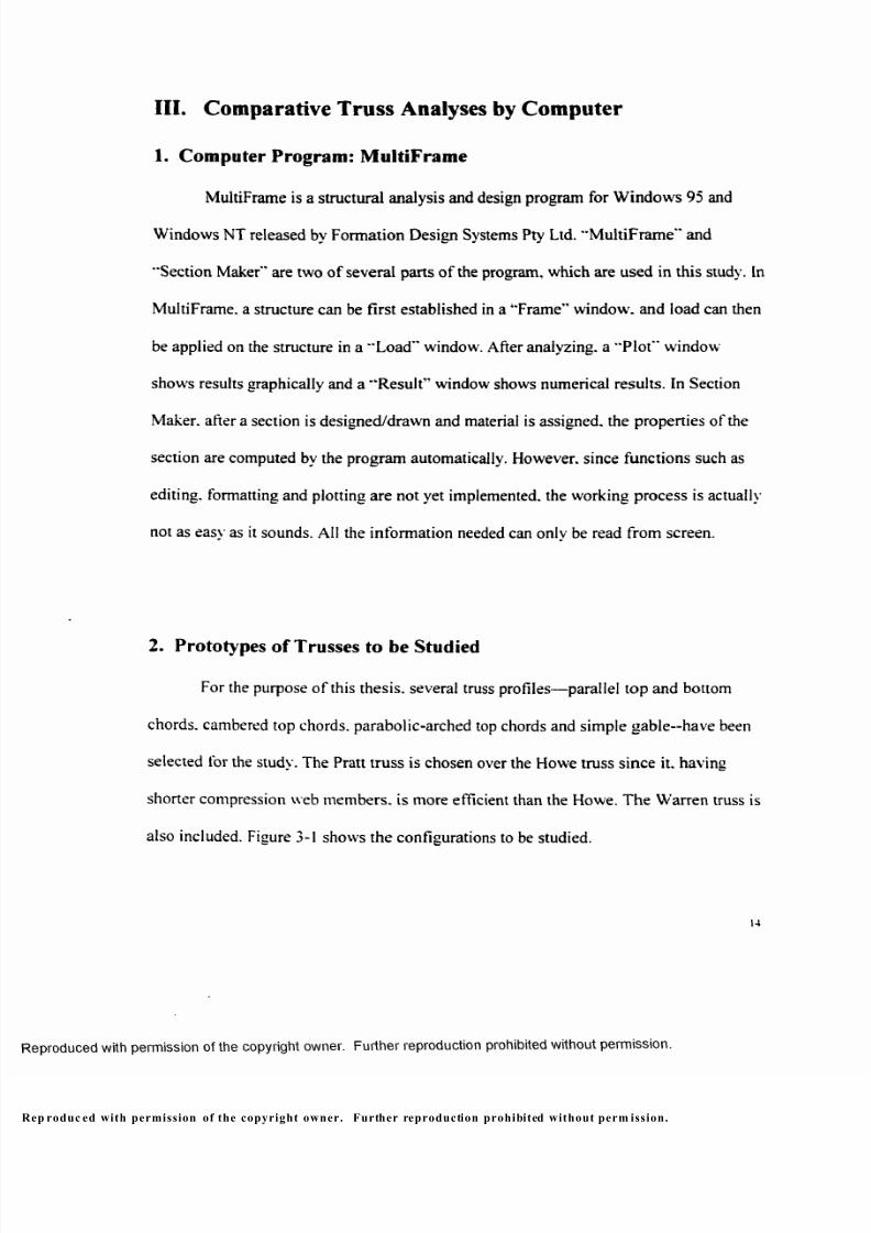
2. Prototypes o f Tru sses to be Studied
For the purpose of this thesis, several truss profiles—parallel top and bottom
chords, cambered top chords, parabolic-arched top chords and simple gab le—have been
selected for the study. The Pratt truss is chosen over the Howe truss since it. having
shorter compression web members, is more efficient than the Howe. The Warren truss is
also included. Figure 3-1 shows the configurations to be studied.
u
p roduc ed with permission of the copyright owner. Further reproduction prohibited without perm ission.
8/9/2019 Steel Roof Truss Optimization
http://slidepdf.com/reader/full/steel-roof-truss-optimization 25/98
a Simple Pitt Pntt with Ptnllel Top dt Bottom Chords
p
? p
T
P
f P
TPT
P P
T
& Mures
P /?
■ s —
c Fist Pntt with Ctabend Top Chord
-P TV
P /2
v
d Arched Top Chord Pntt
p
i
P /2
e Simple Gtble Pntt
Span = L
Figure 31 Prototypes of Trusses to be Studied
pro du ced with perm ission of the copyright owner. Further reproduction prohibited without permission .
8/9/2019 Steel Roof Truss Optimization
http://slidepdf.com/reader/full/steel-roof-truss-optimization 26/98
From practical experience, a height to span ratio of 1:10 is assumed for the
parallel-chord Pratt and the Warren trusses: a ratio o f 1:8 for the cambered top and
arched top Pra tt trusses; and 1:5 for the gable truss. The average o f the height to span
ratios of ail these trusses is actually 1:10. which would make this comprehensive truss
configuration-vveight study more meaningful since a choice o f either truss for a roof of a
specific building would add no other variables to the building.
It is obvious that the roof slope o f the gable is 2:5: the slope o f the cambered
Pratt is designed as 1:10.
Panel size is assumed to be 25 feet.
The truss span ranges from 100 feet to 300 feet at a 50-foot interval. Figure 3-2
shows a complete study schedule. It needs to point out that the panel size of 100-ft span
group is not 25 feet but 12.5 feet. Except for that, all the above configuration
assumptions apply to all trusses.
An indefinite roofing plan of a grid of "Span o f Truss x 30ft " is assumed.
Therefore, the truss spacing is 30 feet on center (Figure 3-3).
p rod uced with perm ission of the copyright owner. Further reproduction prohibited without permission.
8/9/2019 Steel Roof Truss Optimization
http://slidepdf.com/reader/full/steel-roof-truss-optimization 27/98
Spta
ottpppp)
A / W W \I'sNNPlA'i
100-ft Spta
ISO-ft Spta
/S7WWVAArxjxTxfxI/l/Txu-n
200-ft Spta
NT xinM^I/I/PIT I
250-ft Spta
A A 7 W W W W V \
300-ft Spta
Figure 3-3 Ro of Trus s Arrangem ent
Figure 3-2 Overall Study Schedule
8/9/2019 Steel Roof Truss Optimization
http://slidepdf.com/reader/full/steel-roof-truss-optimization 28/98
3. Simulation Assumptions
The following assumptions are made for structural analysis:
• A planar truss is a rigid structure composing of straight bars that are lying in
the same plane and connected to one another through frictionless single pin
joints;
• All members are assumed to be perfectly straight and of constant cross
section: their centroidal axes coincide with the centroid of the joint:
• Bracing has been provided at panel joints in the direction perpendicular to
the plane of the truss and the load of the bracing has been included in the roof
dead load:
• Only vertical static load is considered in this study and the load is applied at
joints through ro of construction except that in combined stress study:
• Forces act in the same plane of the truss plane:
• Displacement of truss is small and hardly influences the magnitude of the
force flow.
rod uced with permission of the copyright owner. Further reproduction prohibited without permission .
8/9/2019 Steel Roof Truss Optimization
http://slidepdf.com/reader/full/steel-roof-truss-optimization 29/98
4. Static Loads
As it has been mentioned before, the principal sources and types of loads on
trusses include gravity dead loads, gravity live loads, wind loads and seismic loads,
among which only vertical static loads are considered in this study.
According to the Uniform Building Code, the live load of a roof is assumed to
be 12psf since the tributary area of all trusses is over 600 square feet. For a typical metal
deck roof construction, ro of dead load is assumed as 20psf exclusive of the weight o f
the truss itself, which is a subject of this study.
Assumption of Sel f-W eight of Trusses
The flat Pratt trusses at all spans are selected for self-weight assumption study.
A 3psf is first assumed and. therefore, the concentrated load at central joints o f the truss
of 100-ft span is
P = (12-20-3) x 12.5x30 = 13.1251b = 13.125Kips;
for the trusses spanning 150-ft to 300-ft. the load is
P = (12-20-3) x 25 x 30 = 26.250lb = 26.25Kips.
The internal axial forces are calculated by MultiFrame and quick designs are
done as 1) top and bottom bars are based on mid-span critical bars: 2) vertical and
diagonal bars based on critical bars at the ends of truss span (Figure 3-4).
pr odu ced with perm ission of the copyright owner. Further reproduction prohibited without perm ission.
8/9/2019 Steel Roof Truss Optimization
http://slidepdf.com/reader/full/steel-roof-truss-optimization 30/98
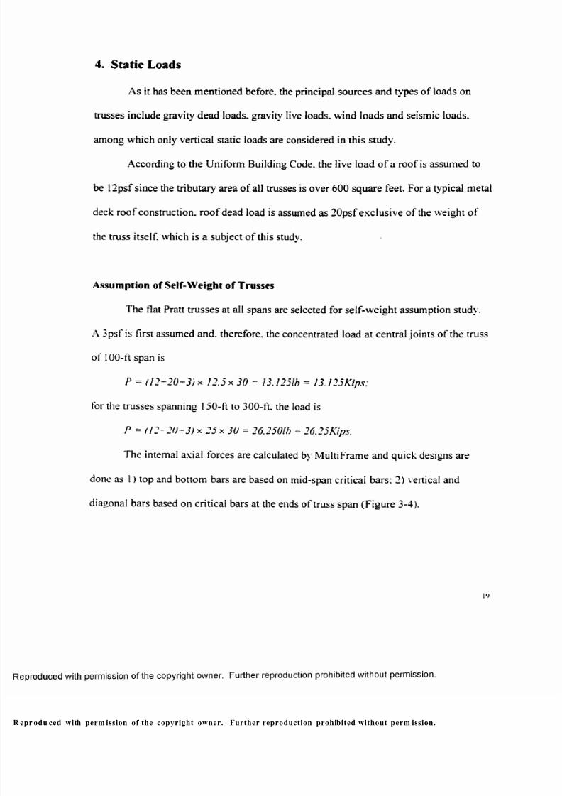
F i g u r e 3 4 C r it ic a l B a n a t Q u i c k D e s ig n
Truss member selections are recorded in the following table.
Table 3-1 Quick Design o f Flat Pratt Trusses o f 3psf Self-Weight A ssumption
Truss Top Chord Bottom Chord Vertical Bar Diagonal Bar
Par-100 WT7X30.5 WT5X19.5 DL3.5X3.5X3/8 DL3X3X5/16
Par-150 WT10.5X55.5 WT 12X27.5 DL5X5X3/8 DL5X5X5/16
Par-200 W T12X73 WT7X4I DL6X6X5/8 DL6X6X3/8
Par-250 WT 15X86.5 WT7X49.5 DL8X8X1/2 DL6X6X3/8
Par-300 WT 15X95.5 WT 10.5X61 DL8X8X3/4 DL8X8X1/2
The design result shows that the assumption of 3psf is only true for the 100-ft
span truss and the self-weights o f all others are far beyond the assumption (Chart 3-1 -1).
So different assumptions have to be made for trusses of different spans separately
according to the first trial as follows: 5psf for 150-ft span. 7psf for 200-ft span. 9psf for
250-ft span and 13psf for 300-ft span. The concentrated loads at central joints for the
trusses of 100-ft to 300-ft spans are calculated as follows:
:o
ro du ced with perm ission of the copyright owner . Further reproduction prohibited without perm ission.
8/9/2019 Steel Roof Truss Optimization
http://slidepdf.com/reader/full/steel-roof-truss-optimization 31/98
Prziooj, = (12+20+3) x 12.5* 30 = 13,1251b = 13.125K ip;
Paisof t = (12+20 +5 ) x 25 x 3 0 = 27,7501b = 2 7. 75K ip;
P<3200 ft = (12+ 20+ 7) x 2 5 x 3 0 = 29.2501b = 29.75Kip:
Pa250ft = (1 2+2 0+9 ) X 25 X 3 0 = 30.7501b = 30.75Kip;
P 3300 /, = (12+20+13) x 25 x 30 = 33.7501b = 33.75Kip.
A second series of designs is recorded in Table 3-2 and results prove that the
assumptions of the trusses from 150-ft to 250-ft span are good enough and that o f the
300-ft span truss seems slightly lower than the result (Chart 3-1-2). In light of the fact
that, in these quick design, truss chord internal force reductions along their span are not
considered, which will be considered in the later study, the assumption of 13psf of 300-
ft span truss is taken as acceptable.
Table 3-2 Quick Design of Flat Pratt Truss o f Different Self-Weight Assumptions
Truss Top Chord Bottom Chord Vertical Bar Diagonal Bar
Par-100 WT7X30.5 WT5XI9.5 DL3.5X3.5X3/8 DL3X3X5/I6
Par-150 WT12X58.5 WT9X30 DL6X6X3/8 DL5X5X3/8
Par-200 WT 13.5X80.5 WT9X43 DL6X6X5/8 DL6X6X3/8
Par-250 WT 15X95.5 WTI5X58 DL8X8X1/2 DL6X6X12
Par-300 WTI6.5X120.5 WT 18X80 DL8X8X1 DL8X8X1/2
All further studies are. therefore, based on these assumptions.
pro duc ed with perm ission o f the copyright owner. Further reproduction prohibited without perm ission.
8/9/2019 Steel Roof Truss Optimization
http://slidepdf.com/reader/full/steel-roof-truss-optimization 32/98
Chart 3-1-1 Truss Weight Assumption - Trial One
1 2
10
M
5* 6
I«L® 4
CO
I Self-Weight
-A s s u m p t i o n
P a r -1 0 0 P a r -1 5 0 P a r -2 0 0 P a r -2 5 0 P a r -3 0 0
Span (ft.)
Chart 3-1-2 Truss Weight Assumption - Trial Two
14
12
10
Mar 8£CD
| 6a>
CO
I Self-Weight
-A s s u m p t i o n
P a r -1 0 0 P a r -1 5 0 P a r -2 0 0 P a r -2 5 0
Span (ft.)
P a r - 3 0 0
e pro du ced with perm ission of the copyright owner. Further reproduction prohibited without permission.
8/9/2019 Steel Roof Truss Optimization
http://slidepdf.com/reader/full/steel-roof-truss-optimization 33/98
5. Com paring Self-W eight of Trusses o f Different Con figurations
The purpose o f this study is to compare the self-weights o f trusses o f different
configurations/types at different spans. A typical construction o f structural Tees for top
and bottom chords and equal-leg double angles for web members (Figure 2-7a) is
selected for the study.
Two series o f loading conditions are simulated -symm etric loading o f roof live
load applied through out the span of trusses and asymmetric loading of roof live load
applied on the right half of the whole span. Structural analyses are performed by the
MultiFrame and internal axial forces of all truss members are given by the program.
Figure 3-5 is a reproduction of internal axial force diagrams of the 200-ft spam
trusses. For the symmetric loading situation, critical compressive and tensile forces (C
and T in the figure) of the parallel chord Pratt and the Warren occur at mid-span in the
top and bottom chords and at the ends of span in web members. When the top chords
are cambered, the maximum compressive forces shift away from the mid-span a litter
bit but overall force pattern remains similar. For the arched-top and gable Pratt trusses,
the situation seems quit different from the above three cases. The force distributes
evenly over the top and bottom chords o f the arched-top Pratt, and there is no force in
the web members at all. For the gable, the critical forces of the top and bottom chords
occur at the ends of the truss span and the force in the web bars, being uneven in length,
distributes more evenly than those of parallel-chord and cambered-chord trusses.
e pro duc ed with perm ission of the copyright owner. Further reproduction prohibited without permission.
8/9/2019 Steel Roof Truss Optimization
http://slidepdf.com/reader/full/steel-roof-truss-optimization 34/98
w r D L i L L ( s h o w n in f i g . J - 1 )
1-2936-
234J ------------------------J
L2 5 6 V '~4461-
'-256P
w i D L
Tw / DL 4 LL
-2466-
90C 246V __
r
" *1 __
Eg N Tto a c“ T __ _ J---
i—m -----------------------
L26 6V ~- — -4241-^--. - - -236P
Symmetric Lotdiog Asymmetric Lading
Figure 3-5 Interna l Axial Force Diagrams of 200 ft Span Trusses(Continuous line Compre ssion; Dashed line: tensi on. Drown in Scole. Unit: Kip.)
8/9/2019 Steel Roof Truss Optimization
http://slidepdf.com/reader/full/steel-roof-truss-optimization 35/98
For the asymmetric loading situation, force patterns of all cases look similar to
those o f the symmetric loading situation. However, the critical forces occur at the live
load side, but are less than those in the symmetric loading situations. Except that, some
small compressive and tensile forces occur in the web members o f arched-chord trusses.
So. the selection o f the web members of arched-chord trusses should be based on the
asymmetric loading situation, while all others should be based on the symmetric loading
situation.
In consideration o f uneven distribution o f force in truss chords and limitation of
the length cf steel elements being able to be transported (less than 60 feet), design of top
and bottom chords are done for every other panel (50 feet per piece) except for the 100-
ft span cases. For simplicity, however, truss web members are designed as vertical or
compressive bars and diagonal or tensile bars in accordance with their critical
compressive and tensile forces.
p rodu ced with perm ission of the copyright owner. Further reproduction prohibited without permission.
8/9/2019 Steel Roof Truss Optimization
http://slidepdf.com/reader/full/steel-roof-truss-optimization 36/98
5.1. Design of Steel Compressive Members
By assuming all trusses are braced at their panel joints, all compressive members
are designed for their own lengths.
Theoretically, design o f a compressive bar is a trial and error process, since the
allowable stress is a function of L/r . with L being the full length o f the member and r
being that for the weak axis, which cannot be known until the member is chosen.
However, the selection can be easily done by using available Column Design tables in
the AISC Manual, in which allowable compression loads have been predetermined for
specific lengths of various elements.
Example: Select a structural Tee o f A36 steel from AISC for a top chord o f the 200ft-
span parallel Pratt with C = 293 kips (Figure 3-5).
Solution:
From the data in table, we can make following reasonable choices:
a) WT12 x 81— KL = 26 ft . allowable Cxv = 342.298 kips:
b) WT13.5 x 80.5 — KL = 26 ft. allowable Cxv = 367 309 kips;
c) WT15 x 86.5— KL = 26 ft . allowable Cxy = 387/324 kips.
The lightest section— WT13.5 x 80.5— is the best choice.
26
p rodu ced with permission of the copyright owner. Further reproduction prohibited without perm ission.
8/9/2019 Steel Roof Truss Optimization
http://slidepdf.com/reader/full/steel-roof-truss-optimization 37/98
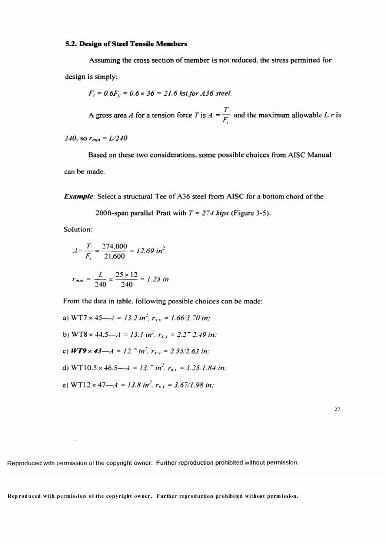
5.2. Design of Steel Tensile Members
Assuming the cross section of member is not reduced, the stress permitted for
design is simply:
F, = 0.6Fy = 0.6 x 36 = 21.6 Icsi fo r A36 steel.
T A cross area A for a tension force T isA = — and the maximum allowable L r
F,
240. so rmm = L/240
Based on these two considerations, some possible choices from AISC Manual
can be made.
Example : Select a structural Tee o f A36 steel from AISC for a bottom chord of the
200ft-span parallel Pratt with T - 274 kips (Figure 3-5).
Solution:
, T 274.000 A = — = ----------- = 12.69 in
F, 21.600
L 25 x 12 _ J mtn — I ^ IH
240 240
From the data in table, following possible choices can be made:
a) WT7 x 45 — A = 13.2 in'. rxv = 1.66'3.70 in:
b) WT8 x 44.5— A = 13.1 in'. rxv = 2.2~ 2.49 in:
c) WT9-X. 43 — A = 12. ~ in'. rxv = 2.55/2.63 in:
d) WT10.5 x 46.5— A = 13. ~ in'. rxv = 3.25 1.84 in:
e) WT12 x 47 — A = 13.8 in2. rxv = 3.67/1.98 in:
p rodu ced with permission of the copyright owner. Further reproduction prohibited without perm ission.
8/9/2019 Steel Roof Truss Optimization
http://slidepdf.com/reader/full/steel-roof-truss-optimization 38/98
f) WT13.5 x 47 — A = 13.8 in2, rxy = 4.16/2.12 in;
g) WT15 x 49.5 — A = 14.3 in2, rxy = 4.71/2.10 in.
The lightest section—WT9 x 43--is the best choice.
All trusses are designed to have lightest possible weight and designs are
recorded in Appendix A.
5.3. Comparison of Truss Self-Weight and Deflection
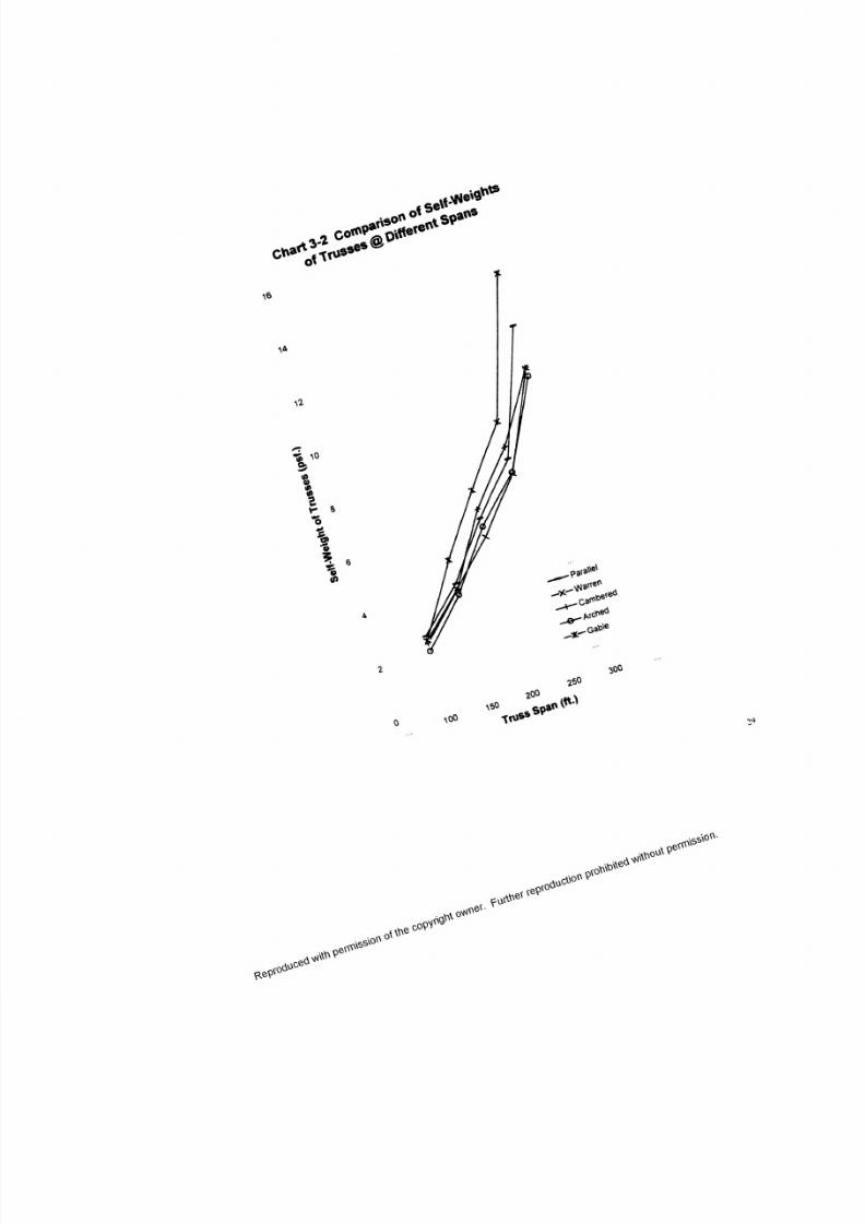
Total weight (in pounds per square foot) of all trusses shown in Figure 3-2 are
plotted in Chart 3-2. It is obvious that the self-weights o f trusses increase unlinearly
after a 250-ft span and the weight differences among trusses of different configurations/
types increase as trusses span longer. The biggest differences are 0.56psf. 1,29psf.
1.75psf. 1.93psf and 3.83psf for 100-ft to 300-ft span groups respectively. They are. in
other words. 26.4%. 34.4%. 32.1%. 26.3% and 36.3% increases based on each group's
lightest cases.
The arched-chord Pratt has the lightest self-weight among all truss
configurations/types at all spans except 200-ft span. The irregular situation at 200-ft
span, where the Warren weighs least, seems to be caused by the limitation of steel
sections and the roughness of design. And actually, the Warren, being the second
lightest truss type, weighs very close to the arched-chord Pratt at all spans. The
28
p rod uced with perm ission o f the copyright owner. Further reproduction prohibited without permissio n.
8/9/2019 Steel Roof Truss Optimization
http://slidepdf.com/reader/full/steel-roof-truss-optimization 39/98
o 'SeV
X &
t ^ u s s c S
at ' s
\ 6
8/9/2019 Steel Roof Truss Optimization
http://slidepdf.com/reader/full/steel-roof-truss-optimization 40/98
cambered-chord Pratt weighs alm ost the same as the Warren and less than the parallel
Pratt at the shorter spans o f 100-ft and 150-ft and the longer span of 300-ft: but at the
mid spans o f 200-ft and 250-ft. it weighs more than the parallel one. which could be
also caused by the roughness of the design. The gable has highest weight at all spans
except at 10 0 - f t .
Chart 3-3 compares the self-weight o f every truss with its original self-weight
assumption. The arched-chord Pratt, having the lowest self-weight, is 1.466psf lower
than the assumptions on average; the Warren, the second lightest truss type, is 1.378psf
lower: being the third and fourth, the cambered-chord and the parallel-chord Pratt
trusses are 0.99psf and 0.732psf lower than the assumptions respectively; the heaviest
truss type, the gable one. having higher self-weight than the assumptions o f 5psf .7psf.
9psf and 13psf from 150-ft through 300-ft spans, has slightly higher self-weight
(0.282psf) than the assumptions on average.
While the self-weights o f both top/bottom chords and web members increase
constantly for all truss types along with the increase of their spans, we observe that the
proportion of the web member weight increases and eventually exceeds that of chords
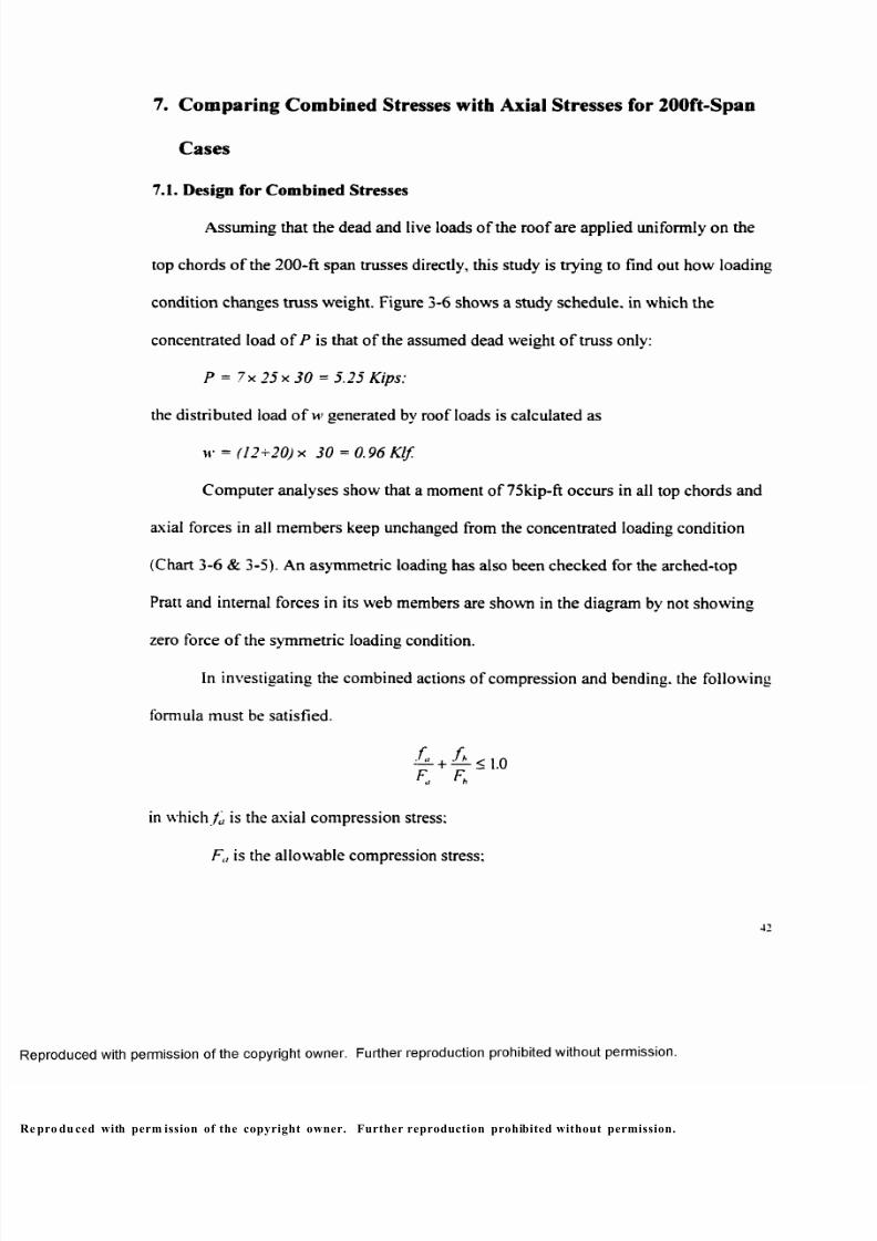
for some cases at longer spans (Chart 3-4). The average percentages o f web member
weight are 45.36%. 42.5%. 47.37%. 32.08% and 42.44% for the five groups
respectively. According to truss span, the average percentages o f web members are
33.37%. 36.78%. 42.98%. 45.93% and 52.2% from 100-ft to 300-ft span.
p rodu ced with perm ission of the copyright owner. Further reproduction prohibited without permission.

8/9/2019 Steel Roof Truss Optimization
http://slidepdf.com/reader/full/steel-roof-truss-optimization 41/98
1 6
14
12
(0Q. 10
.2* 8
is= 6 o
CO
Chart 3-3 Comparison of Truss Weights with Assumptions
—O — T op /B ot . — X — W eb • T ot al - A ssu m p ti o n
coQ.
coQ.
o
I
0mCM
1
oIf )
e<0a
oIf )CM
ECO
O
oIf )
oIf )CM
Oif )
X>CO
O
oIf )CM
oTruss Type - Span
16
^ 14
a 12tT 10
8
6
4
2
0
Chart 3-4 Comparison of Top/Bottom Chordswith Web Members
I T o p /B o t . O W e b
a
1. . i
a>co
ca
CO 100%
8 0 %
60 %
o ©o oCM CM
CO COQ . 5
.Oa5ofl■S 40%
Oa
20%
0%
□ W e bTop /Bo t
Truss Type - Span
e prod uced with permission of the copyright owner. Further reproduction prohibited without permission.

8/9/2019 Steel Roof Truss Optimization
http://slidepdf.com/reader/full/steel-roof-truss-optimization 42/98
Assuming the allowable deflection of truss with both dead and live roof loads
being L/240, which means 5 inches, 7.5 inches. 10 inches, 12.5 inches and 15 inches for
100-ft to 300-ft span respectively, the design results and compute r analyses show that all
trusses have far less deflections than the allowables (Chart 3-5). The average deflections
of 100-ft to 300-ft span trusses are 1.91 inches, 2.75 inches, 3.70 inches. 4.84 inches and
5.92 inches respectively. They are 38.2%. 36.67%. 37.00%, 38.72% and 39.47% of their
allowables.
Chart 3-5 Truss Deflection
Arc-300 — ------- ----- ---
W a r-3 00 i i ^ m m ' - - - •
Arc-250
W a r -2 5 0
etoQ.
CO
^ A r c- 20 0
aK W a r -2 0 0
Arc-150
W a r -1 5 0
Arc-100
W a r -1 0 0
0
□ A l l o w a b l e■ Def l ec ti on
6 8 10 12 14 16
Deflection (in.)
pr odu ced with perm ission of the copyright owner. Further reproduction prohibited without perm ission.
8/9/2019 Steel Roof Truss Optimization
http://slidepdf.com/reader/full/steel-roof-truss-optimization 43/98
It is interesting to notice that, while the gable Pratt has the highest self-weight at
almost all spans, it has the smallest deflection at all spans~an average of 32.71% of
allowable deflection amount—among all truss types. The second to the fifth are the
cambered Pratt—36.04%. the arched Pratt—38.56%. the Warren— 40.19% and the
parallel Pratt— 42.61%.
It needs to be pointed out that, in reality, the flat roof system shall be
investigated to assure adequate strength and stability under ponding conditions, which is
out o f the scope o f this study.
5.4. Conclusions
Trusses seem to be very economic structure types at a span less than 250 feet:
after this point, their self-weight increases non-linearly.
Truss configuration has an increasing impact on weight as the truss span
increases. The parabolic-arched-top shape, which follows a beam's moment curve, is
the most effective configuration by distributing internal forces/stresses even in its top
and bottom chords and dramatically reducing those in its web members. The cambered-
chord Pratt, surprisingly, does not show superiority over the paralle 1-chord Pratt at some
spans. Between the two parallel-chord ones, the Warren has more even internal
forces/stresses distribution and lighter self-weight than the Pratt over all spans. The
gable has reasonable self-weight only at small spans: so it seems not a good choice for
longer spans.
pro duc ed with perm ission o f the copyright owner. Further reproduction prohibited without permissio n.
8/9/2019 Steel Roof Truss Optimization
http://slidepdf.com/reader/full/steel-roof-truss-optimization 44/98
The deflection o f a planar truss seems not to be a big concern except ponding
needs to be considered.
6. Com paring TS Construction with the WT&DL
Structural tube is used in this series of design o f chosen cases (100-ft. 200-ft and
300-ft span) in order to compare with the construction o f WT&DL. Loading conditions
and design methods are basically the same as the study before. However, there are two
points which need to be noticed: 1) the structural tube is o f A46 steel instead of A36: 2)
the selections o f member sections must have comparable dimensions in order to be
constructed and transfer load efficiently (Figure 2-7b).
pro du ced with perm ission of the copyright owner . Further reproduction prohibited without perm ission.
8/9/2019 Steel Roof Truss Optimization
http://slidepdf.com/reader/full/steel-roof-truss-optimization 45/98
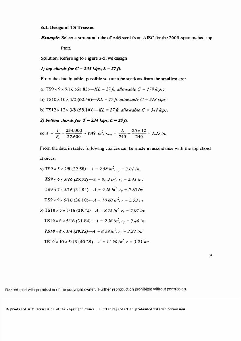
6.1. Design of TS Trusses
Example'. Select a structural tube of A46 steel from AISC for the 200ft-span arched-top
Pratt.
Solution: Referring to Figure 3-5. we design
1) top chords fo r C = 255 kips, L = 27ft.
From the data in table, possible square tube sections from the smallest are:
a) TS9x 9 x9 /16 (61.83)— KL = 27ft. allowable C = 279 kips:
b) TS10 x 10 x 1/2 (62.46) — KL = 27 ft. allowable C = 318 kips:
b) TS12 x 12 x 3/8 (58.10))— KL = 27ft. allowable C = 341 kips.
2) bottom chords fo r T = 234 kips, L = 25 ft.
. T 234.000 . . . . , L 25x12 soA = — = ------------= 8.48 in . rmm =------= ----------- = 1.23 in.
F, 27.600 240 240
From the data in table, following choices can be made in accordance with the top chord
choices.
a) TS9x 5 x 3/8 (32.58)— A = 9.58 in2. i\ = 2.0/ in:
TS9 x 6 x 5/16 (29.72)—A = 8.73 in2. ry = 2.43 in:
TS9 x 7 x 5/16 (31.84)—.-! = 9.36 in2. ry = 2.80 in:
TS9x 9x 5/16 (36.10 )— A =10.60 in2, r = 5.55 in
b) TS10 x 5 x 5/16 (29. ~2)—A =8.73 in'. rv = 2.07 in:
TS10 x 6 x 5/16 (31.84)— A =9.36 in'. rv = 2.46 in:
TSIOx 8 x 1/4 (29.23) — A = 8.59 in'. rv = 3.24 in:
TS10 x 10x 5/16 (40.35)— A = 11.90 in', r = 3.93 in:
pro du ced with perm ission of the copyright owner. Further reproduction prohibited without permission .
8/9/2019 Steel Roof Truss Optimization
http://slidepdf.com/reader/full/steel-roof-truss-optimization 46/98
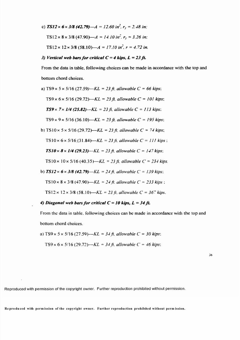
c) TS12 X 6x3/8 (42.79)— A = 12.60 in2, ry = 2.48 in;
TS12 x 8 x 3/8 (47.90) — A = 14.10 in2, r , = 3.26 in;
TS12 x 12x 3/8 (58.10)— A = 17.10 in2, r = 4.72 in.
3) Vertical web bars fo r critical C = 4 kips, L = 23 ft.
From the data in table, following choices can be made in accordance with the top and
bottom chord choices.
a) TS9 x 5 x 5/16 (27.59) — KL = 23 ft, allowable C = 66 kips:
TS9 x 6 x 5/16 (29.72)— KL = 23 ft, allowable C = 101 kips:
TS9 x 7x 1/4 (25.82)— KL = 23 ft, allowable C = 113 kips:
TS9 x 9 x 5/16 (36.10)— KL = 23 ft, allowable C = 195 kips:
b) TSIOx 5 x 5/16 (29.72) — KL = 23ft. allowable C = 74 kips;
TS 10x 6 x 5/16.(31.84)— KL = 23ft, allowable C = 111 kips :
TSIO x 8 x 1/4 (29.23)— KL = 23 ft, allowable C = 147 kips:
TS10 x 10x 5/16 (40.35) — KL = 23 ft. allowable C = 234 kips.
b) TS 12x 6 x 3 /8 (42.79)— KL = 24ft, allowable C = 139 kips:
TSIOx 8 x 3/8 (47.90) — KL = 24ft. allowable C = 233 kips :
TS12x 12 x 3/8 (58.10) — KL = 23 ft. allowable C = 367 kips.
4) Diagonal web bars fo r critical C= 10 kips, L = 34 ft.
From the data in table, following choices can be made in accordance with the top and
bottom chord choices.
a) TS9 x 5 x 5/16 (27.59) — KL = 34 ft. allowable C = 30 kips:
TS9 x 6 x 5/16 (29.72)— KL = 34 ft. allowable C = 46 kips:
36
pro du ced with perm ission of the copyright owner. Further reproduction prohibited without perm ission.
8/9/2019 Steel Roof Truss Optimization
http://slidepdf.com/reader/full/steel-roof-truss-optimization 47/98
TS9 x 7 x 1/4 (25.82)— KL = 34 ft, allowable C = 55 kips:
TS9 x 9 x 5/16 (36.10)— KL = 34 ft, allowable C = 118 kips:
b) TS 10 x 5 x 5/16 (29.72 )— KL = 34 ft, allowable C = 34 kips:
TS 10 x 6 x 5/16 (31.84)— KL = 34 ft , allowable C = 51 kips :
TSIO x 8 x 1/4 (29.23)— KL = 34ft, allowable C = 81 kips:
TSIOx 10x 5/16 (40.35)— KL = 34ft, allowable C = 162 kips.
c) TSI2 x 6 x 3/8 (42.79) — KL = 34 ft, allowable C = 69 kips:
TS 12 x 8 x 3/8 (47.90)— KL = 34 ft, allowable C = 134 kips :
TS 12 x 12 x 3/8 (58.10)— KL = 34 ft, allowable C = 289 kips.
Total weights o f TS9. TS10 and TS12 designs are 26,9901b, 28.1041b and 34.2071b
respectively. Since smaller section seems to achieve lighter truss weight, let us try TS8
sections, starting from a rectangle tube for the top chords.
1) Top chords:
TSIOx 8 x 5/8 (67.82)—KL = 27ft. allowable Cxv = 326/260 kips.
2) Bottom chords:
TS8 x 4 x 1/2 (35.24 )— A = 10.40 in : . ry = 1.54 in:
TS8 x 6 x 3/8 (32.58 )— A = 9.58 in " . i\ = 2.36 in:
TS8 x 8 x 5/16 (31.84)— A = 9.36 in 2 , r = 3.12 in:
TSIOx 8x 1/4 (29.23)—A = 8.59 in 2. ry = 3.24 in.
3) Vertical web bars:
TS 8x 4 x 1/4 (19.02)— KL = 24 ft , allowable C = 27 kips.
p roduc ed with perm ission o f the copyright owner. Further reproduction prohibited without perm ission.
8/9/2019 Steel Roof Truss Optimization
http://slidepdf.com/reader/full/steel-roof-truss-optimization 48/98
4) Diagonal web bars:
T S 8 x 6 x 1/4 (22.42)—KL = 24ft, allowable C = 70 kips.
Total weight o f the TS8 truss is summed as 26.6151b. so it is the best choice.
By the same procedure, another 14 trusses are designed to have the lightest
possible weight and the designs are recorded in Appendix B.
6.2. Comparing with the WT&DL Construction
Chart 3-6 shows self-weights of all TS trusses. The weight differences between
trusses of different configurations/types increase, just like those o f the WT&DL trusses,
as trusses span longer, but they are not as dramatic as those of the WT&DL trusses. The
biggest differences are 0.29psf. 0.41psf. and 2.27psf for 100-ft to 300-ft span groups,
which are 13.74%. 8.45%. and 24.3% increases based on each group's lightest cases.
Except for the gable, the weight o f all other trusses increase almost linearly from 100-ft
to 300-ft span, which is different from the WT&DL trusses.
pro duc ed with perm ission o f the copyright own er. Further reproduction prohibited without permissio n.
8/9/2019 Steel Roof Truss Optimization
http://slidepdf.com/reader/full/steel-roof-truss-optimization 49/98
Chart 3-6 Comparison of Self-Weights of
Tube Trusses @ Different Spans1 0
10
(0o(0(03
o>
£ £"5
CO
— P ara ll e l
-X— W a r r e n
C a m b e r e d
- © — A r c h ed
-X — G a b le
100 200
Truss Span (ft.)
3 0 0
rod uced with perm ission of the copyright owner. Further reproduction prohibited without perm ission.
8/9/2019 Steel Roof Truss Optimization
http://slidepdf.com/reader/full/steel-roof-truss-optimization 50/98
The arched-chord Pratt still weighs least among all truss types at all spans. The
cambered Pratt is the second lightest one this time. The Warren switches to the third
place. At 100-ft and 200-ft spans, the gable Pratt has lower weight than the parallel Pratt
and at 300-ft span , the gable weights most.
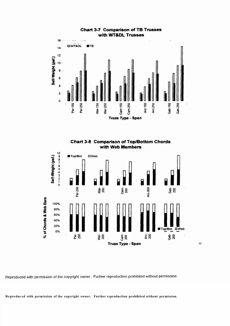
Chart 3-7 compares the self-weights o f TS trusses with those o f WT&DL
trusses. It shows obvious weight reduction at all cases. At 100-ft span, the truss weight
reduces 20.43% on average; at 200-ft span. 24.95%; at 300-ft span. 32.6%.
The truss weight distribution between its top/bottom chords and web members is
similar as that o f the WT&DL truss (Chart 3-8 and 3-4). The weights o f truss chords and
web members increases straightly for all truss types along truss span, and the proportion
of the web members increases as truss spans longer.
6.3. Conclusions
In concern o f the self-weight of truss, the tubular construction is more economic
than the WT&DL one. Reasons must be: 1) the TS sections have higher stress capacity:
2) tube sections have more even gyration radius between .v-.v and y-y axis, which makes
the use of material more efficient.
pro duc ed with permission of the copyright owner. Further reproduction prohibited without perm ission.
8/9/2019 Steel Roof Truss Optimization
http://slidepdf.com/reader/full/steel-roof-truss-optimization 51/98
% o f C h o r d s & W e b B a r s
Chart 3-7 Comparison of TB Trusseswith WT&DL Trusses
16
14
^ 12
«a10 •
£8
12 6o
W 4
2
0
□ WT&DL IT B
o oin in
CM
CQ0 .
CQCL
O Oin wCM
| |
o oin in■»- CM
E £CO CO
O O
#o
iO
o
mCM
6<
o
m-OtoO
Truss Type - Span
Ma
o>
£
a>to
10
9
87
65
4
3
21
0
Chart 3-8 Comparison of Top/Bottom Chordswith Web Members
I T o p /B o t . □ W e b
8
100%
80 %
60%
40%
20%
0%I T o p / B o t. D W e b
.o o to o O ^
Truss Type - Span
pro duc ed with perm ission of the copyright owner. Further reproduction prohibited without permission.
G a b - 2 5 0
8/9/2019 Steel Roof Truss Optimization
http://slidepdf.com/reader/full/steel-roof-truss-optimization 52/98
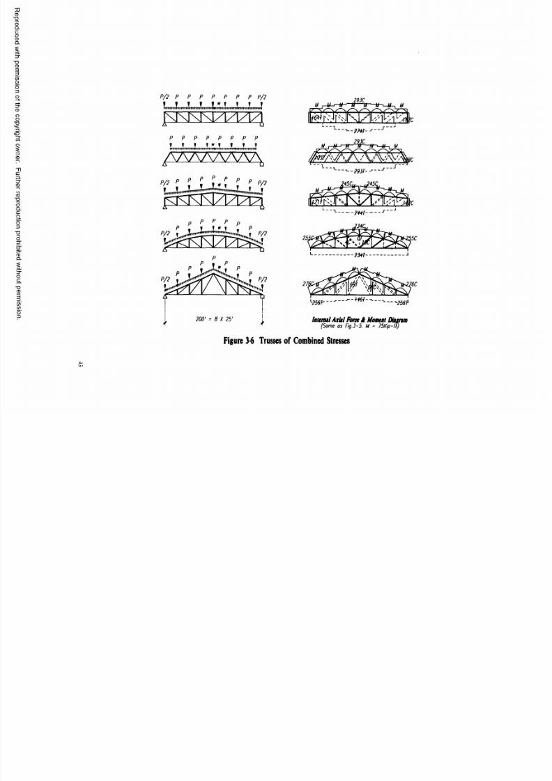
7. Com paring Combined Stresses with Axial Stresses for 200ft-Span
Cases
7.1. Design for Combined Stresses
Assuming that the dead and live loads of the roof are applied uniformly on the
top chords of the 200-ft span trusses directly, this study is trying to find out how loading
condition changes truss weight. Figure 3-6 shows a study schedule, in which the
concentrated load of P is that of the assumed dead weight o f truss only:
P = 7 x 25 x 30 = 5.25 Kips;
the distributed load of w generated by roof loads is calculated as
w = (12+20) x 30 = 0.96 Klf.
Computer analyses show that a moment of 75kip-ft occurs in all top chords and
axial forces in all members keep unchanged from the concentrated loading condition
(Chart 3-6 & 3-5). An asymmetric loading has also been checked for the arched-top
Pratt and internal forces in its web members are shown in the diagram by not showing
zero force o f the symmetric loading condition.
In investigating the combined actions of compression and bending, the following
formula must be satisfied.
f f — + — < 1.0
in which f a is the axial compression stress:
Fa is the allowable compression stress;
42
pro du ced with perm ission of the copyright owner. Further reproduction prohibited without permission.
8/9/2019 Steel Roof Truss Optimization
http://slidepdf.com/reader/full/steel-roof-truss-optimization 53/98
P/ 2 P P P P P P P P/ 2
T f T f f ^ T T T T
p p p p p p p p
T T T TH'T ? ¥ ?
; j { i . J c f
/ 0 0 ' = B X 25
29JC j — m — tr-Ttr-
29JC
-zW-
gfflf wl2S6F--- --^■256fi
latenul Axiil Force 1 Moaeat Ditgrtm(Some os Fig.J-5. M = 75Kip-lI)
Figure 3-6 Trusses of Co mbined Stresses
4-04

8/9/2019 Steel Roof Truss Optimization
http://slidepdf.com/reader/full/steel-roof-truss-optimization 54/98
f , is the actual bending stress;
Fb is the allowable bending stress.
Designing such a member is a trial and error process. Following steps are set up
to do the work. 1) find the area (A) and section modules (S) required if the actions of
compression and bending occur separately; 2) find possible sections with higher values
of both A and S from the step one; 3) verify the combined effect of compression and
f f bending o f one section at one time: if the formula — + — < 1.0 is satisfied, the section
Fa FH
is OK: but if — + — « 1.0. the section mav be more than enough~a section with a F, Fhd n
slightly lower A and/or S’values needs to be checked following the same procedure: if
~ r + — > 1.0. the section is not adequate and a section of higher A and/or S values*. F'ha n
must be verified and used.
Exam ple: Select a structural tube of A46 steel for the top chord o f the 200-ft span
arched-top Pratt with C = 255 kips and M = 75 kip-ft (Figure 3-6).
Solution:
1) For Ur = 50. Fa = 22.66 ksi
required A - — = --------% 11.25 in. F 22.66
For noncompact section. Fb = 0.6Fy = 0.6 x 46 = 27.6 ksi
Required S = -
4 4
e prod uced with perm ission o f the copyright owner. Further reproduction prohibited without permission .
8/9/2019 Steel Roof Truss Optimization
http://slidepdf.com/reader/full/steel-roof-truss-optimization 55/98
2) For a first try. let us double both of A and 5 values and look for steel sections with
A = 2 x 11.25 =22.50 in.2
S = 2x32.61 =65.22 in.3
From AISC. we find following possible sections:
a) TS14x 10 x 1/2—w = 76.07p l f A = 22.4 in.2, Sx = 86.9 in.3, rx = 5.22 in.
b) TS12 x 12 x1/2—w = 76 .07plf, A = 22.4 in.2. S = 80.9 in.3, r = 4.66 in.
c) TS14 x 14 x 1/2— vv = 89.68 plf, A = 26.4 in.2. S = 113 in 3, r = 5.48 in.
3) Verify a) TS14 x 10 x 1/2
f , = — = — * 11.38 ksi. A 22.4
L r = =s 62, therefore Fa = 20.94 ksi.
M 75x12 Jb = — = --------- ' 10.36 ksi.
S 86.9
, 10 190 _ub. t = -— = 20 < - t— =28 => compact section,
X2
therefore Fb = 0.66FV= 0.66 x 46 = 30.36 ksi.
f L + f L= + 10^6 ^ Q 54 ^ = <
F, Fh 20.94 30.36
So the section ofT S1 4x 10 x 1/2 is OK! From previous experience, the design
of smaller section (TS 10) is lighter than that of bigger one (TS12). The sections of
TS12 x 12 x 1/2 and TS14 x 14 x 1/2 need not to be checked. Furthermore, a section of
45
p rodu ced with permission of the copyright owner. Further reproduction prohibited without permission.
8/9/2019 Steel Roof Truss Optimization
http://slidepdf.com/reader/full/steel-roof-truss-optimization 56/98
TS9 can not be found for the top chord, TS10 sections should be best choice. TS10 for
other members need to be picked.
Another four trusses are designed in the same way and designs are recorded in
Appendix C.
7.2. Comparing with the Joint Loading Cases and Conclusion
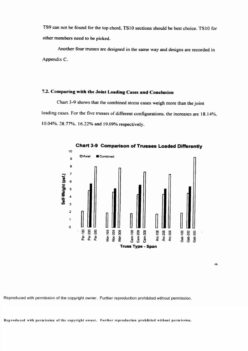
Chart 3-9 shows that the combined stress cases weigh more than the joint
loading cases. For the five trusses of different configurations, the increases are 18.14%.
10.04%. 28.77%. 16.22% and 19.09% respectively.
10
9
8
-r- 7to
B 6
® 5
55 4
CO 3
Chart 3-9 Comparison of Trusses Loaded Differently
□ A x i a l ■ C o m b i n e d
o o o o o oo o o o o o*■“ CM CO CM CO
CQ CQ CQ (0 CQ CQQ . 0 . CL
§ § 5
oo
E(0O
ooCM
ECQ
O
ooCO
ECQ
o
o o oo o o
CM CO
O o< <
oo
ACQ
o
ooCM
ACO
o
ooCO
.oCQ
o
Truss Type - Span
46
rodu ced with perm ission of the copyright owner. Further reproduction prohibited without perm ission.
8/9/2019 Steel Roof Truss Optimization
http://slidepdf.com/reader/full/steel-roof-truss-optimization 57/98
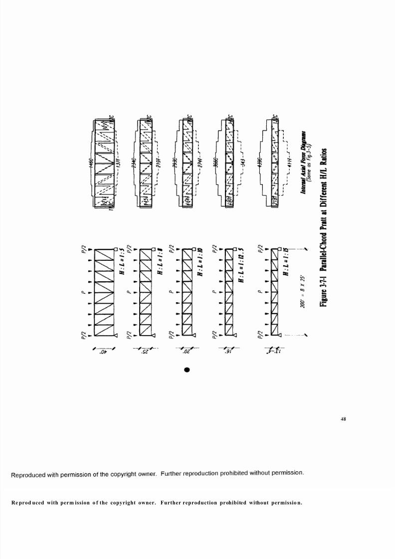
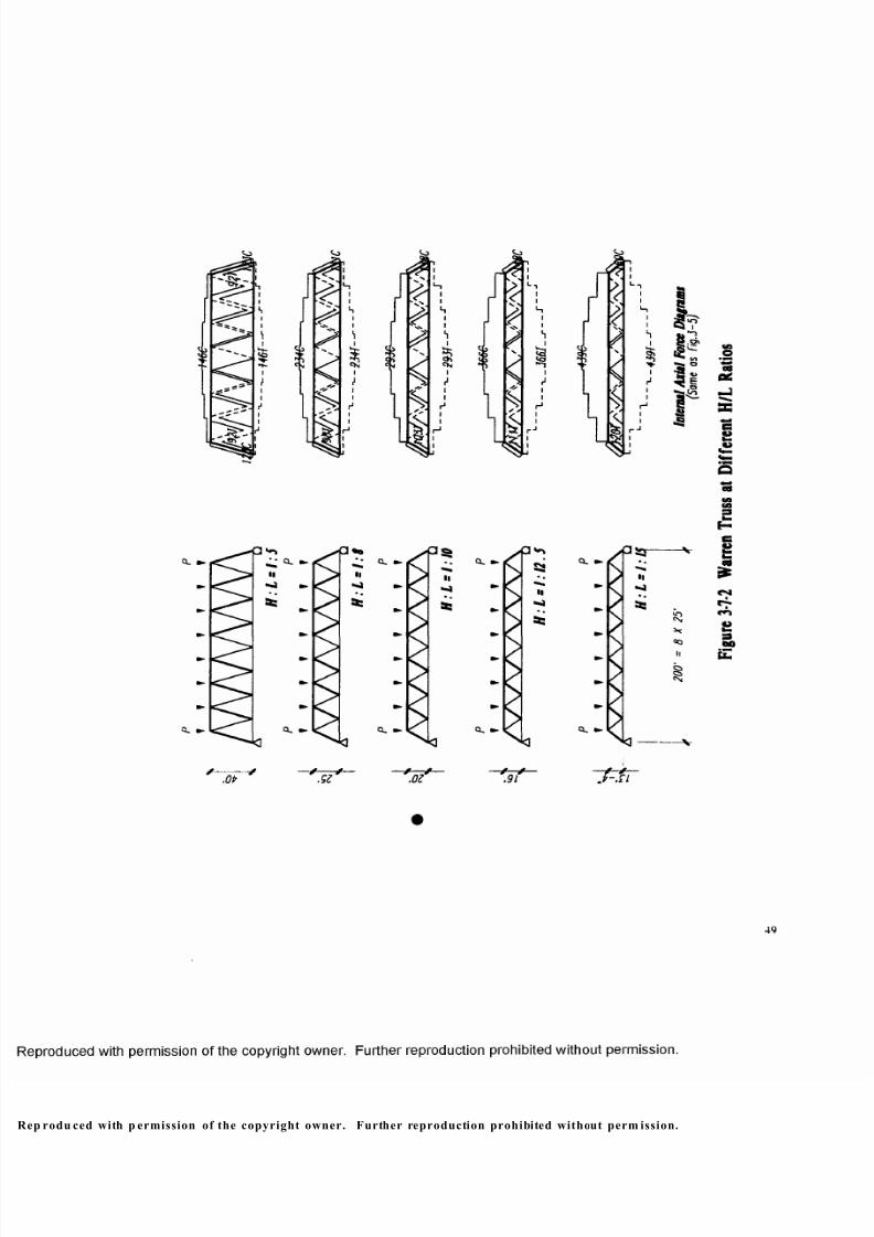
8. Com paring D ifferent H /L Ratios for 20 0-ft Span C ases
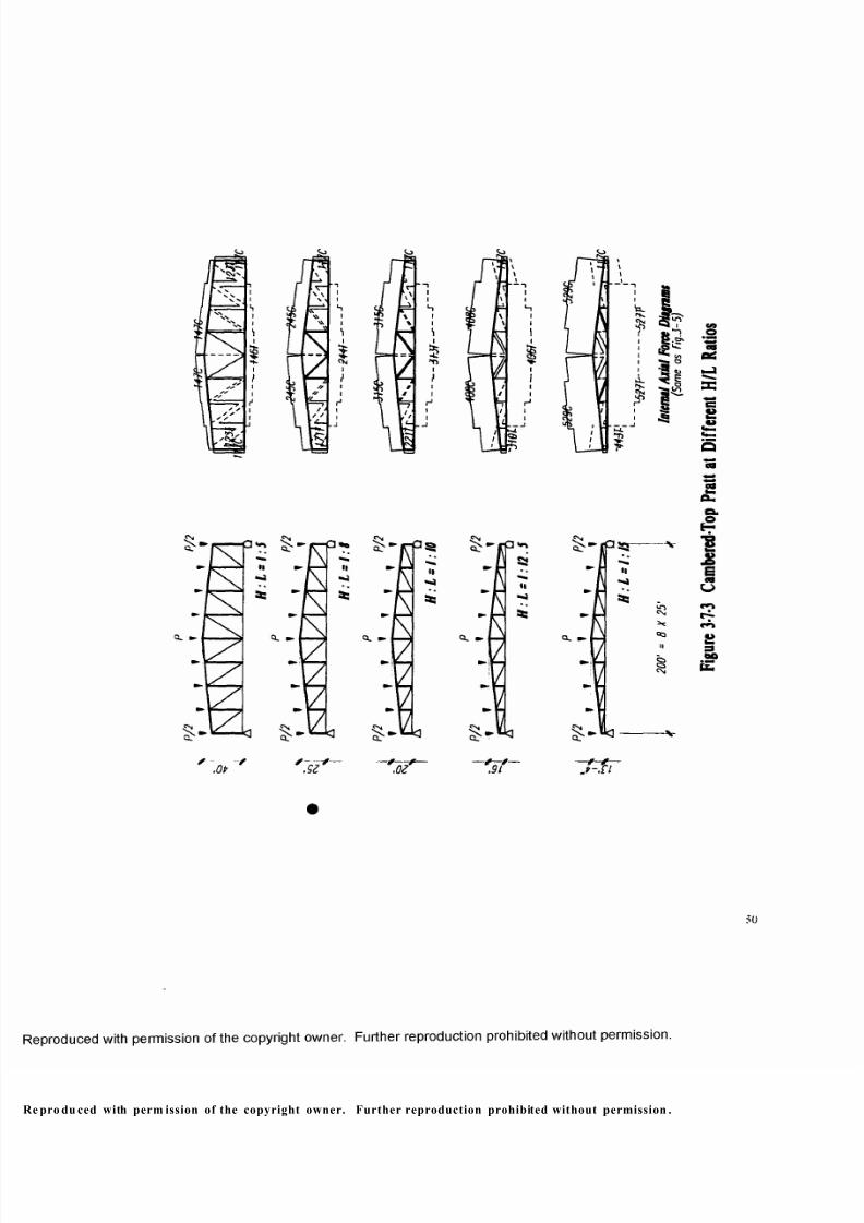
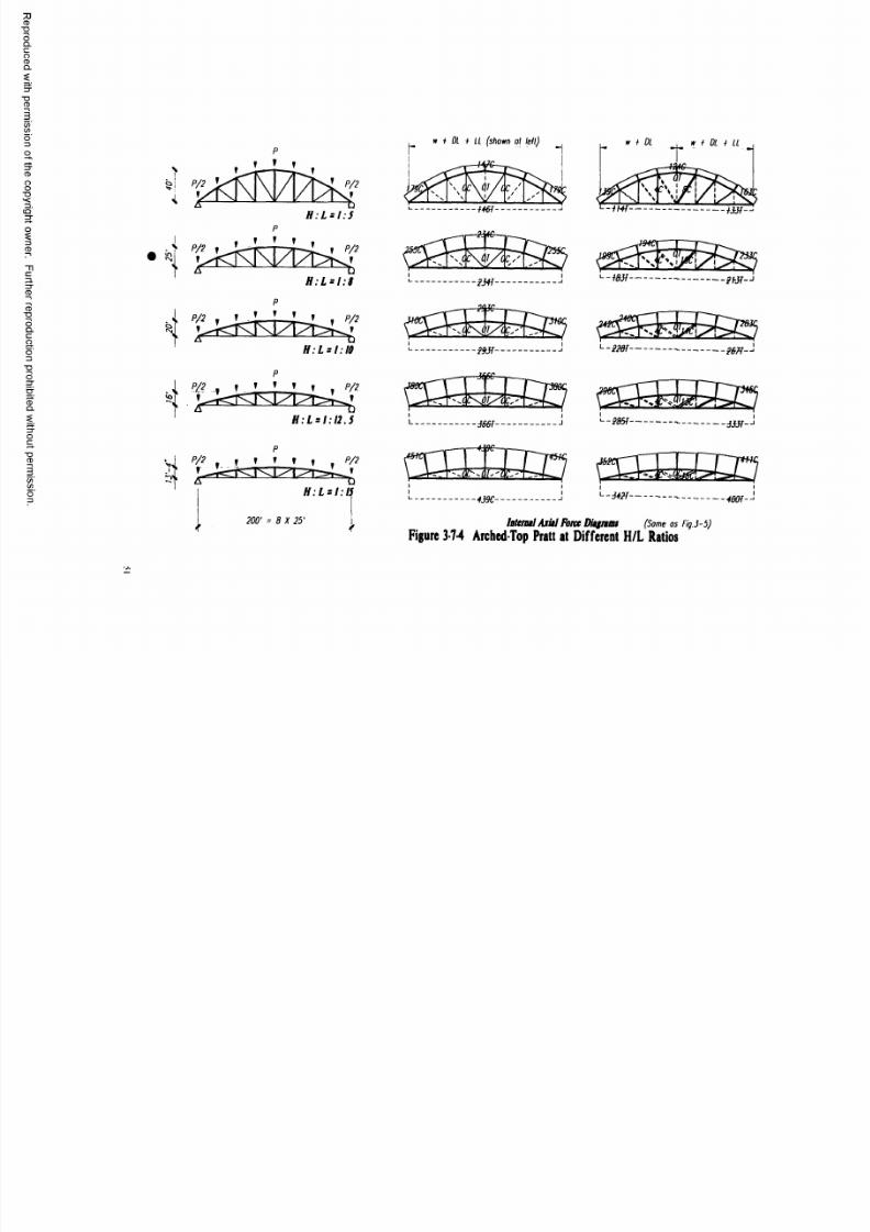
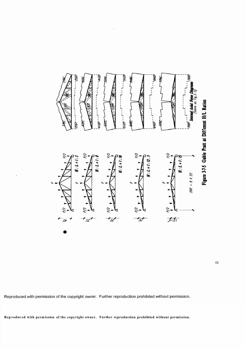
8.1. Ratios of 1/5,1 /8,1/10,1 /12 .5 and 1/15
The height-to-span ratio o f trusses is to be studied to see how it affects the self
weight of trusses. Ratios o f 1/5. 1/8, 1/10. 1/12.5 and 1/15 are assumed to 200-ft span
trusses. Figure 3-8 shows complete study schedules (big dots show the original cases in
previous study) and internal ax ial force diagrams reproduced from MultiFrame. It is not
surprising to see that the lower the truss, the larger the compressive and tensile forces in
top and bottom chords. While vertical bars change lengths, the magnitude of the
compressive force in them remains unchanged. However, from higher to lower trusses,
tensile force in diagonal bars becomes larger in order to have the same amount of
vertical component to resist the same amount of shear force o f the truss viewed as a
beam.
Structural tubes are used in this series of designs. Design procedure is the same
as that in the section 6 and designs are recorded in Appendix D.
rodu ced with permission of the copyright owner. Further reproduction prohibited without permission.
8/9/2019 Steel Roof Truss Optimization
http://slidepdf.com/reader/full/steel-roof-truss-optimization 58/98
m
e
e prod uced with perm ission o f the copyright owner. Further reproduction prohibited without permissio n.
8/9/2019 Steel Roof Truss Optimization
http://slidepdf.com/reader/full/steel-roof-truss-optimization 59/98
m
e
‘N\
\ \
4%
I
H
$
%V >
r ❖
/ >»
<❖
§
j#<
\
<
&
i
ia
.OP
^ 0. ► 0. •> Q. ►
O. ►
' , o z ' / /.91 - p t i
49
p rodu ced with p ermission of the copyright owner. Further reproduction prohibited without perm ission.
F i g u r e
3 - 7
- 2
W a r r e n
T r u s s
a t D i f f e r e n
t H / L
R a
t i o s
8/9/2019 Steel Roof Truss Optimization
http://slidepdf.com/reader/full/steel-roof-truss-optimization 60/98
\ I 5}i
}
p-K
o
CU •»
Q> f *r
x .0* ' .S t , o t .5 /
\
'Z
I
>-r /
<*>n
*?
1£eCQ
50
e pro du ced with perm ission of the copyright owner. Further reproduction prohibited without permission .
8/9/2019 Steel Roof Truss Optimization
http://slidepdf.com/reader/full/steel-roof-truss-optimization 61/98
H:L = l: 5 p
T T f
T P/2
H;L = l: 8
T T T
p/2 T T ft*
H:L * / : ,
..1 ft? f ? ' ! * T T /*/?
H : L = 1:1 2.5
7*
H: L = 1; I.
200' = 8 X 25'
i OL i LL (shown ol left)
--2MT --------------- L-fft H ----------------------- M - J
------
n !L - 2m ----------
L ------------------------- --------------------------J
-4&&
i !■285T --------------------------------------
Atff-
C S d rK E p n s t s s c n-439C-
i iJ ---------------------- - 4 m -
latemil Axitl Farce Dugnai (Some as Fig.j-5)
Figure 3-7-4 Arched-To p Pratt at Dif feren t H/L Ra tios
8/9/2019 Steel Roof Truss Optimization
http://slidepdf.com/reader/full/steel-roof-truss-optimization 62/98
roduc ed with perm ission of the copyright owner. Further reproduction prohibited without permission.
8/9/2019 Steel Roof Truss Optimization
http://slidepdf.com/reader/full/steel-roof-truss-optimization 63/98
8.2. Comparison and Conclusions
Self-weights o f the 15 trusses are plotted in Chart 3-10-1. It is c lear that the
parallel-chord Pratt and the Warren have the lightest weight at a height-to-span ratio o f
1/10; the cambered-chord Pratt has the lightest weight at 1/8; the arched-chord has the
same and lightest weight at 1/8 and 1/5; and the gable Pratt has the lightest weight at
1/5. In each truss configuration/ type group, the worst case could raise the truss weight
up to 36.83%. 47.65%. 73.97%, 36.49% and 103.90% of the lightest case. It seems that
the height-to-span ratio is a key fact to the self-weight of trusses.
Chart 3-10-2 and 3-10-3 show more details. We see that the self-weights of
chords go straight up as trusses get lower. However, the tricky part is the weight o f web
members. On one hand, in the higher truss, the vertical web bars are actually designed to
have reasonable slenderness ratios rather than resisting forces/stresses. On the other
hand, in the lower truss, the diagonal web bars need to be designed to resist much bigger
tensile forces. Combined result is that a medium height-to-span ratio around 1/10 seems
better.
p roduc ed with perm ission o f the copyright owner. Further reproduction prohibited without perm ission.
8/9/2019 Steel Roof Truss Optimization
http://slidepdf.com/reader/full/steel-roof-truss-optimization 64/98
Chart 3-10-1 Comparison of Self-Weights of
Trusses @ Different Height-to-Span Ratios
10
<0a« 6a>«M3
t 5O
at
5 4
"35to
- P a r
- X — W ar
—I C a m
-© — A rc
-X — G ab
“ " “ A ssu m .
1to5 1to8 1to1 0 1to12.5 1to15
Height-to-Span Ratio
pro du ced with perm ission of the copyright owner. Further reproduction prohibited without permission .
8/9/2019 Steel Roof Truss Optimization
http://slidepdf.com/reader/full/steel-roof-truss-optimization 65/98
aco 3
2
1
Chart 3-10-2 Comparison of Self-Weight of Trusses@ Different H/L Ratios
1 0
9
8
‘a 7 S.r e£® 5o
5 4
—O — T op/ B ot .
• T otal
—X— W eb
— A ss um pti on
V < v <
a cm•i oCQ
o- ti.(Qa
00oI
tnCM
0
1
00o mCM
E £ CO I
O EcoO
u<
mCM
2o<
Truss Type - H/L Ratio
i i CMr-
.o 2COOCO
O
(0
O)
I£a>co
10
9
8
7
6
5
4
3
2
1
0
Chart 3-10-3 Comparison of Self-Weight of Trusses@ Different H/L Ratios
□ W e b
■ T o p / B o t .
co in2 oi
1 5ra »-O Aa
O
Truss Type - H/L Ratio
R eprod uced with permission of the copyright owner. Further reproduction prohibited without permission.

8/9/2019 Steel Roof Truss Optimization
http://slidepdf.com/reader/full/steel-roof-truss-optimization 66/98
9. Comparing Different Panel Sizes for 200-ft Span Cases
9.1. Panel Sizes of L/4, L/6, L/8, L/10 and L/12
The panel size of trusses is to be studied to see how it affects the self-weight of
trusses. Panels o f L/4. L/6, L/8, L/10 and L/12 are assumed for 200-ft span trusses.
Figure 3-8 shows complete study schedules (big dots show the original cases) and
internal axial force diagrams reproduced from MultiFrame. The critical compressive and
tensile forces in top and bottom chords remain unchanged in all cases while the lengths
of truss chords change. While the critical compressive forces in the vertical bars at the
ends o f a span remain unchanged, the critical tensile forces in the diagonal bars at the
ends of the span get smaller in shorter panel size cases. A different situation is that of
the Warren: the smaller the panel size, the smaller the compressive forces, but the larger
the tensile forces in web members.
Structural tubes are used in this series o f designs. The design procedure is the
same as that shown in the section 6 and designs are recorded in Appendix E.
p rodu ced with permission o f the copyright owner. Further reproduction prohibited without permission.
8/9/2019 Steel Roof Truss Optimization
http://slidepdf.com/reader/full/steel-roof-truss-optimization 67/98
4 X SO"Fuel
2P/3 4P/3 2P/3
1 1 1 1 1 1 1
6 X 33'-4’ Ptnel
P /2 P P /2
iX 2f Ptael
2P/5 4P/5 2P/5
1 1 1 1 1 1 1 1 1 1 1
A D10 X 20" Ptael
P /3 2P /3 P /3
1 1 1 1 1 1 1 1 1 1 1 1 1
p w i i w w| 12 X If-T Ptael
L 20 0 ' '
-2936-
-2J6T'i
-249P J
-2936 ----- •------
1------ 260 f ------r
-2936-
-2936-
■— -284 P-
- 2 9 3 6 -
SSSSEOZBSSM"^ -'-'-2 84 3'-'~-r'
latenul Axitl Font Diigrtau(Some as fig.3-5 )
F i g u r e 3 -8-1 P a r a l l e l - C h o r d P r a t t o f D i f f e r e n t P a n e l S iz e s
Vi —J
8/9/2019 Steel Roof Truss Optimization
http://slidepdf.com/reader/full/steel-roof-truss-optimization 68/98
4P/3 4P/3
1 1 1 1 1 1
P P
4P/5 4P/5
1 1 1 1 1 1 1 1 1 1
f j w w w w \
2P/3 2P/3
1 1 1 1 1 1 1 1 1 1 1 1
/ W T O M A A A A A
12 X W4T
_________ i 293C i __________
4 X SO*Fuel -iWF
/ \ / \ / \ / \ / \ / \6 X W r P t a t l ' 1— 293T — r
/ v w w v v x8X2fPioel X" "L- — ------------J" " J
w / W \ / V V A V /
--2934'-
20 0 ' | Internal Axitl Force Diignms(Some os Fig.3-5)
F i g u r e 3- 8* 2 W a r r e n T r u s s o f D i f f e r e n t P a n e l S i z e s
oc
8/9/2019 Steel Roof Truss Optimization
http://slidepdf.com/reader/full/steel-roof-truss-optimization 69/98
4 X SO’Prnel
4P/3
P /2
6 X J3’-4mPtne!
P /2
f ^ ^ T \ 1 7 P P T ^ i8 X 2 f Ptoel
4P/5
- T
10X20'Ptx!
2P/J
200 '
-2491- J
1 1------ 2401------1 1
" I - --------------!44T ^ -- T -
456 — IT
- — -2441- — -
Intend Ad d Farce Ditgnat (Some os Fig.J-5)
F i g u r e 3- 8- 3 C a m b e r e d - T o p P r a t t o f D i f f e r e n t P a n e l S i ze s

8/9/2019 Steel Roof Truss Optimization
http://slidepdf.com/reader/full/steel-roof-truss-optimization 70/98
4 XSV Fuel
2P/3 ?
6 X 33’-4’ Fuel
t X 2 f Pint!
AP/5
» »__!» f * T 2P/5
10X20'PtotI
2P/3
» j J r m - T L L i T P/i
12 X I f r Fuel
2 0 0 ' latcm tl Axial Force Ditgnms (Some os Pig.3-5)
Figure 3-8-4 Arched-Top Pratt of Diffe ren t Panel Sizes
8/9/2019 Steel Roof Truss Optimization
http://slidepdf.com/reader/full/steel-roof-truss-optimization 71/98
61
pro du ced with perm ission of the copyright owner. Further reproduction prohibited without perm ission.
F i g u r e
3 - 7 - 5
G a b
l e
P r a t t o f
D i f f e r e n
t
P a n e l
S i z e s

8/9/2019 Steel Roof Truss Optimization
http://slidepdf.com/reader/full/steel-roof-truss-optimization 72/98
9.2. Comparison and Conclusions
Self-weights of the 15 trusses are shown in Chart 3-11-1. At the panels of 16.7-ft
to 33.3-ft. the weights of trusses are pretty close; but at the big panel of 50-ft. trusses
weigh a lot more. Specifically, the 50-ft panel trusses weigh 64.89%, 46.01%, 68.01%.
56.67% and 48.68% more than the best cases in five truss groups respectively. Except in
the 50-ft panel cases, the differences are jus t 9.33%. 3.05%. 10.66%. 10.77% and
8.99%.
Chart 3-11-2 and Chart 3-11-3 show more details. We see that the self-weights
of the chords go down steeply, just like the total weights of trusses, from 50-ft to 33.3-ft
panel, but go down very slowly from 33.3-ft to 16.7-ft panel. Since the smaller the panel
size, the more the number of vertical bars, but in larger panel cases, diagonal web bars
need to be designed to resist much larger tensile forces at longer length, web bars weigh
less at medium panel sizes. Overall result is that the Warren weighs least at L/8 panel
size of 25-ft and all others weigh least at L/10 panel size of 20-fit.
p roduc ed with permission of the copyright owner. Further reproduction prohibited without permission.
8/9/2019 Steel Roof Truss Optimization
http://slidepdf.com/reader/full/steel-roof-truss-optimization 73/98
Chart 3-11-1 Comparison of Self-Weights of
Trusses with Different Panel Sizes
8
— — P ar
-X— W ar
I Cam
O Arc
■X— G ab
■“ " A s s u m p t i o n
Truss Type - Panel Size
rod uced with perm ission of the copyright owner. Further reproduction prohibited without perm ission.
8/9/2019 Steel Roof Truss Optimization
http://slidepdf.com/reader/full/steel-roof-truss-optimization 74/98
Chart 3-11 -2 Comparison of Self-Weight of Trusseswith Different Panel Sizes
(0O ; 5
3 *
12 3
'sV ) _ >S<-x-*'XXV>fJC'x >Sc-x-x
-T o p /B o t. —X— W e b -T otal -A s s u m p t i o n
tO oCO CM
X XCO oO T -
CO OCO CM
X X
§ 2
CO oCO CM
X XCO oo
CO
0.CQ0. I I
ECQ
oECD
o
CO oCO CM
X X
5 26 6< <
CO oCO CM
X XCO o© ^x> .oCD CD
O O
Truss Type - Panel Size
Chart 3-11 -3 Comparison of Self-Weight of Trusseswith Different Panel Sizes
CA
.5* 4
I3
0)CO
□ W e b
■ T o p /B o t .
Truss Type - Panel Size
ep rodu ced with perm ission of the copyright owner. Further reproduction prohibited without permission.
8/9/2019 Steel Roof Truss Optimization
http://slidepdf.com/reader/full/steel-roof-truss-optimization 75/98
IV. Conclusions and Recommendations
In summary of the previous studies, following conclusions can be drawn:
• Truss configurations have an increasing impact on the weight of the truss as
a truss span increases. The parabolic-arched top chord is the best configuration.
The gable is good only at short spans. The Warren and the cambered-chord Pratt
are usually better than the parallel-chord Pratt.
• A structural tube truss is more economic than WT&DL truss considering the
weight o f the truss alone.
• Direct chord loading could increase truss self-weight about 20% and should
be avoided.
• The height to span ratio plays an important role in reducing truss self-weight.
The study shows that the average ratio of 1/10 is the best ratio. For the parallel-
chord Pratt and the Warren, extremely high ratios should be first avoided: for the
gable, the cambered-top and the arched-top Pratt, extremely low ratios should be
avoided.
• For trusses of the H/L ratio of 1/10. L/10 is also the best panel size for all
Pratt trusses (web bar— 45°); however. L/8 is the best for the Warren (web bar—
50°). Larger panels over L/6 seem very uneconomical because of truss self
weight.
With truss weight alone, the final cost of a truss has not been determined yet.
Joint construction cost, which makes up another part of the total cost, needs to be
65
p rod uce d with perm ission of the copyright owner. Further reproduction prohibited without permission.
8/9/2019 Steel Roof Truss Optimization
http://slidepdf.com/reader/full/steel-roof-truss-optimization 76/98
investigated and the investigation can only be done case by case because the labor cost
is mainly depended on other considerations such as the overall scale of a project, the
availability of skilled labor and etc. There is. actually, no straight forward answer to the
economics of the truss structure according to Professor Dimitry Vergun. who practices
in the field for over 40 years.
However, for a given truss with its span predominantly determined by
architectural concerns, its height-to-span ratio is the most important factor for material
efficiency according to this series study. Bearing this in mind at preliminary design
stage, architects will significantly contribute to architectural and structural synergy.
p rodu ced with perm ission o f the copyright owner. Further reproduction prohibited without permission.
8/9/2019 Steel Roof Truss Optimization
http://slidepdf.com/reader/full/steel-roof-truss-optimization 77/98
Appendix A:
Design of WT&DL Trusses of 100-ft, 150-ft, 200-ft, 250-ft, 300-ft Spans
68-72
Appendix B:
Design of Tube Trusses of 100-ft, 200-ft, 300-ft Spans
73-75
Appendix C:
Design of 200-ft Span Trusses for Combined Stresses
76
Appendix D:
Design o f 200-ft Span Trusses at Different H/L Ratios
77-81
Appendix E:
Design o f 200-ft Span Trusses of Different Panel Sizes
82-86
p rodu ced with permission o f the copyright owner. Further reproduction prohibited without permission.
8/9/2019 Steel Roof Truss Optimization
http://slidepdf.com/reader/full/steel-roof-truss-optimization 78/98
Appendices
Appendix A: Design of WT&DL Trusses
WT7XJ0.5
DL3X3X5/16—^ r ^ r ^ r ^ L A S \ / \ / \ ~-DL4X4X5/l6
__________ WT5X19.5 _________ __
WT7X30.5
DL3X3X3/16 ~ A / \ / \ / \ / \ / \ / \ A - DL5 X5X5/I6
WT7X21.5
WT7X26.5
DL4X4X1/4 — f r s j x l ' x l \ [ / ' | y i / V > - t t W ? / <
__________ WT6X17.5 _________
WT7XJ0.5
DL3 .5X3.5XI/4 - -DL2 .5X 2.5 XJ /I6
WT7X17
WT7XJ0.5
DL4X4X1/4 -DL4X4X1/4
WT7X19
Figure A’l 100-ft Span
68
prod uced with permission of the copyright owner. Further reproduction prohibited without permission .
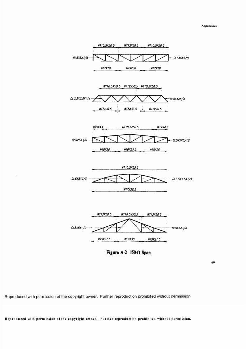
8/9/2019 Steel Roof Truss Optimization
http://slidepdf.com/reader/full/steel-roof-truss-optimization 79/98
Appendices
WT10.SX50.5 WT 12X58.5 WT10.5X50.5
0L5X5X3/8-
WT7X19 WT9X30 WT7X19
— DL6X6X3/8
WT10.5X50.5 WT12X58.5 WT10.5X50.5
DL3.5X3.5X1/4~ -DL6X6X5/8
DL6X8XJ/8-
DL6X6X3/8 —
WT7X26.5 \ WT8X33.5 WT7X26.5
WT9X43 WTI0.5X50.5 WT9X43
WT8X20 WT9X27.5 WT8X20
WT 10.5X55.5
-DL5X5X5/16
— DL3.5X3.5X1/4
WT7X26.5
WT 12X58.5 WT10.5X50.5 WT12X58.5
DL8X8X1/2 — ------ ----- 0L5X5X3/8
WT9X27.5 WT9X38 WT9X27.5
F igu re A-2 150-ft Span
69
p rodu ced with perm ission of the copyright owner. Further reproduction prohibited without permission.
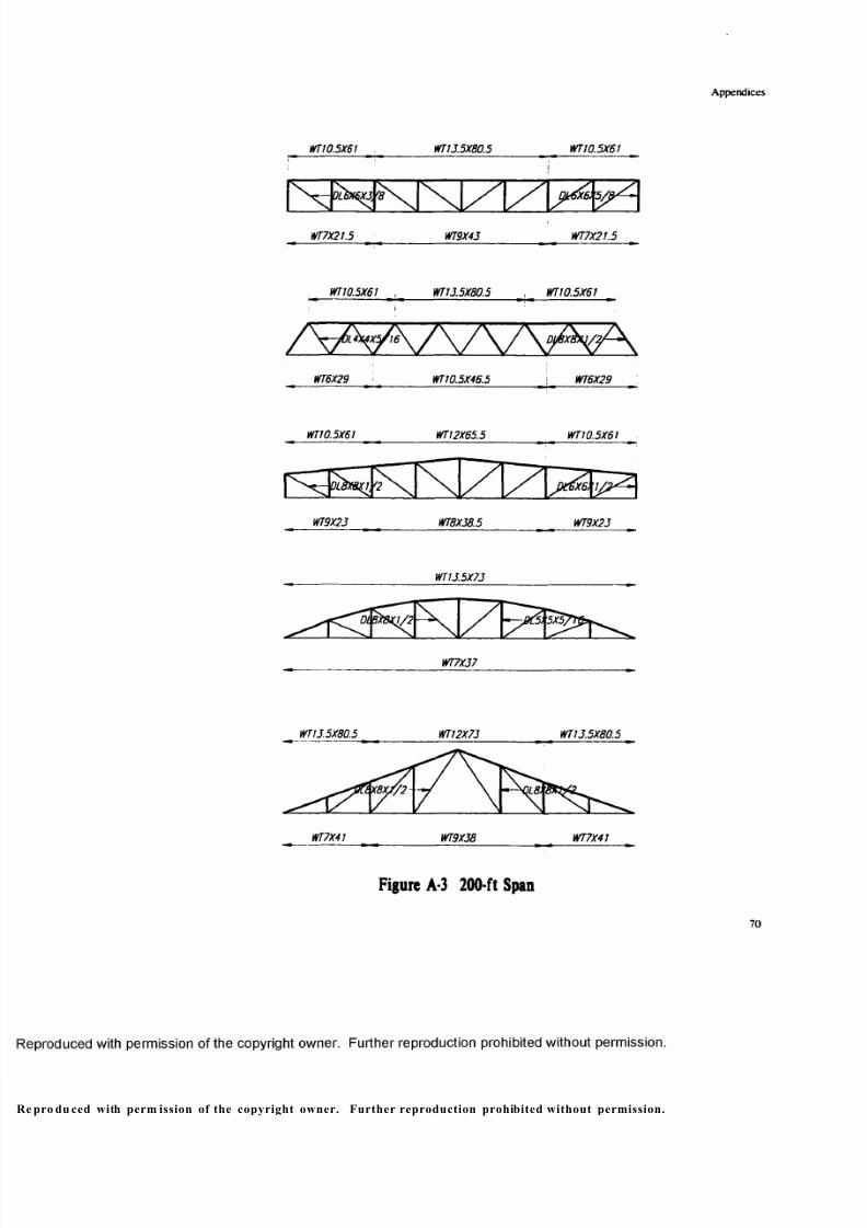
8/9/2019 Steel Roof Truss Optimization
http://slidepdf.com/reader/full/steel-roof-truss-optimization 80/98
Appendices
WT10.5X6 1 . WT15.5X 80 .5 WT 10.5 X61
1 1
016X6X5, QHM6. 5 / p ^
WT7X21.5 WT9X45 WT7X21.5
WT10.5X61 WT15.5X80.5 , WT10.5X61
WT6X29 WT10.5X46.5 WT6X29
WT10.5X61 WT12X65.5 WT10.5X61
NWT9X25 WT8X58.5 WT9X25
WT15.5X75
^ ^ D M K 8 K 1 / 2
WT7X57
WTI5.5X80.5 WT 12X75 WT15.5X80.5
A iWT7X41 WT9X58 WT7X41
Fig ure A-3 200-ft Span
70
pro du ced with perm ission of the copyright owner. Further reproduction prohibited without permission.
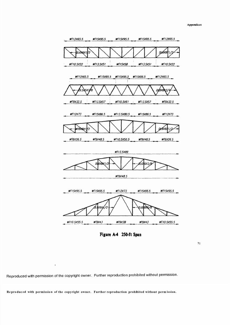
8/9/2019 Steel Roof Truss Optimization
http://slidepdf.com/reader/full/steel-roof-truss-optimization 81/98
Appendices
WT!2X 65 .5 WT!5X95.5 WT15X95.5 WTI5X95.5 WT12X65.5
WT13.5X5J WT! 0.5X22WT10.5X22 WT!3.5X51 WT15X58
WT12X65.5 WT15X9 5.5 WT15X95 .5 WT15X95.5 WT12X65.5
WT9X32.5 WT13.5X57 I WT10.5X61 ■ WT13.5X57 \ WT9X32.5
WT12X73 WT 15X86.5 WT13.5X80.5 . WT15X86.5 WT12X73
WT6X26.5 WT9X48.5 WTJ0.5X50.5 WT9X48.5 WT6X26.5
WT 13.5X89
DL9X8X1/2 6X3/J.
WT9X48.5
WT15X95.5 WT15X95.5 WTI2X73 WT15X95.5 WT15X95.5
X9 XJ /2
WT 10.5X55.5 WT10.5X55.5
Figure A-4 250-f t Span
71
e pro duc ed with permissio n of the copyright owner. Further reproduction prohibited without perm ission.
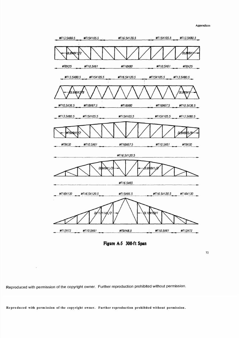
8/9/2019 Steel Roof Truss Optimization
http://slidepdf.com/reader/full/steel-roof-truss-optimization 82/98
Appendices
WT13.5 X8 0.5 WT15X105.5 WT 16.5 X1 20 .5 WT 15X 105 .5 WT 13.5 X80 .5
WT8X25 WT 10.5X61 WT18X80 WT10.5X61 WT8X25
WT13.5X80.5 , WT15X105.5 , WT16.5X120.5 , WT15X105.5 WT13.5X80.5
/ y k \ / \ / \ / \ h N w \ A AWT10.5X36.5 WT18X67.5 WT18X80 WT18X67.5 WT10.5X36.5
WT13.5X80.5 WT15X105.5 WT15X105.5 WT 15X105.5 WT 13.5X80.5
WT9X30 WT10.5X61 WT18X67.5 WT10.5X61 WT9X30
WT16.5X120.5
8X1A
WT 18X130 WT 16.5X120.5 WT15X95.5 WT16.5X120.5 WT18X130
lilt X.
WT12X73 WT10.5X6I WT9X48.5 WT10.5X61 WT12X73
Figu re A-5 300 -ft Span
72
pro du ced with perm ission of the copyright owner. Further reproduction prohibited without permission .
8/9/2019 Steel Roof Truss Optimization
http://slidepdf.com/reader/full/steel-roof-truss-optimization 83/98
Appendices
Appendix B: Design of Tube Trusses
_________ TS6X6X5/J6 _________
TS6XJXJ/16— f K S \ T \ i \ l / l / i / \ S h -TS6X4XJ/16
__________ TS6X4X1/4 __________ _
TS6X6X5/16
!S6X3X3/l6~ / \ / \ J \ J \ / \ / \ / \ / \ r - TS6X5XJ/16
_______ TS6XJX5/16 _______ _
_______ TS6X6X1/4 _______
TS6X3X3/16 — \ l X l X \ / \ / \ s S \— 156X3X3/16
TS6X3X1/4----
_______ 156X6X5/16 _______ _
156X3X3/16 - -156X3X3/16
__ _______ 1S6X5X3/16 ______
1S6X6X5/16
156X3X3/16 -1S6X4X3/16
' __________ 1S6X6X3/16 _________ J
Figu re B-l 100-ft Sp an
73
rodu ced with perm ission of the copyright owner. Further reproduction prohibited without perm ission.
8/9/2019 Steel Roof Truss Optimization
http://slidepdf.com/reader/full/steel-roof-truss-optimization 84/98
Appendices
T S 9 X 9 X 1 / 2 __________ TS9X9X9/16 _________ TS9X9X1/2
TS9X7X1/4 159X6X3/8 TS9X7X1/4
TS9X9X1/2 , T59X9X9/16 , TS9X9X1/2 ,
T S 9 X 7 X 1 / 4 ___________ TS9X9X5/16 _______________ TS9X7X1/4
T S 8 X 8 X 9 / 1 6 ___________ TS10X8X9/16 ______________ TS8X8X9/16
1S8X4X1/4 _______________ TS8X8X5/16 _________ TS8X4X1/4
TS10X8X5/8
TS10X8X1/4
TS9X9X9/16 ___________ T59X9X1/2 _______________ TS9X9X9/16
'7X//4
159X7X1/4 TS9X7X5/I6
Figure B-2 200-f t Span
74
pro duc ed with permissio n of the copyright owner. Further reproduction prohibited without permission .

8/9/2019 Steel Roof Truss Optimization
http://slidepdf.com/reader/full/steel-roof-truss-optimization 85/98
Appendices
T S1 4 X1 0 X 3/ 8 1 5 1 4 X 1 0 X 5 / 8 __________ TS14X10X5/8 ____________ TS14X10X5/8 TS14X10X3/8
TS10X8X9/16 TS 10X8X1/4 TS10X10X3/8 TS10X10XJ/8 TS 10X8X1/4
TS 14X 10X3 /8 TS14X10X5/8 . TS14X10X5/8 , TS14X10X5/8 TS14X10X3/8
TS10X10X1/2TS 10X8X 1/4 TS 10X6X9/16 TS 10X6 X9/16 TS10X8X1/4
TS14X10X3/8 TS14X10X1/2 _____________ TS14X10X1/2 _____________ TS14X10X1/2 TS14X10X3/8
TS1DX8X /h
TS 10X8 X1/4 TS I OX 10X3 /8 TS 10X6X 9/16 TS10X10X3/8 TS10X8X1/4
TS 14X10 X5/8
fSIL X8 X1 /4
TS10X5X9/16
TS 12X12X5 /8 __ TS12X12X5/ 8 i _____________ TS12X12X1/2 _____________ TS 12X12X5/8 < 75/2X12X5/8
TS 12X1 2X3/8 TS12X8X3/8 TS1 2X8 X3/8 TS 12X12X3/8
Fig ure B-3 300-ft Span
pro duc ed with perm ission o f the copyright own er. Further reproduction prohibited without permissio n.
8/9/2019 Steel Roof Truss Optimization
http://slidepdf.com/reader/full/steel-roof-truss-optimization 86/98
Appendices
Appendix C: Design of 200-ft Span Trusses for Combined Stresses
TS14X10X1/2 ______________ TS14X10X1/2 _________ TS14X10X1/2
TS W 8 X / 4 T ^d xa y i/ ’
TS10X8X1/4 TS10X5XJ/8 TS 10X8X1/4
TS14X10X1/2 , TS14X10X1/2 TS14X10X1/2
/ \ / s% ^ \/\/\/V /V /\TS10X8X1/4 ■ TS 10X8X5/16 ' TS 10X8X1/4
TS 14X10X1/2 TS14X10X1/2 TS14X10X1/2
NTS10X8X1/4 TS 10X6X5/16 TS 10X8X1/4
TS14X10X1/2
^ f ^ J S m 8 K l / 4
TS 10X8X1/4
TS14X10X1/2 TS14X10X1/2 TS14X10X1/2 .
n
TS 10X6X5/16 ' TS 10X8X1/4 i TS 10X6X5/16
F igure C
76
pro duc ed with permission of the copyright owner. Further reproduction prohibited without permission.
8/9/2019 Steel Roof Truss Optimization
http://slidepdf.com/reader/full/steel-roof-truss-optimization 87/98
Appendices
Appendix D: Design of 200-ft Span Trusses at Different H/L Ratios
TS 10X8X1/4 , __________ TSWX10X5/16 _____________ TS10X8X1/4
TS10X8X
TS 10X8X1/4 TS10X8XJ/4 TS 10X8X1/4
T S 8 X 8 X 1 / 2 ____________ TS8X8X5/8 ________________ TS8X8X1/2
T S 8 X 4 X 1 / 4 ____________ TS8X4X3/8 ___________ ; TS8X4X1/4
See Figure B -2
TS10X10X1/2 _____________ TS10X10X9/16 TS10X10X1/2
TS 1 0 X 8 X 1 / 4 __________ TS10X8XJ/8 _________ TS 10X8X1/4
TS10X10X1/2 ____________ TS14X10X5/8 ______________ TSIOXlOXI/2^
TS 10X 8X1 /4 ____________ TS10X6X9/16 ________ TS10X8X1/4
Fi gure D- l Pa ra l l e l C ho rd P ra tt
77
p rodu ced with perm ission of the copyright owner. Further reproduction prohibited without permission.
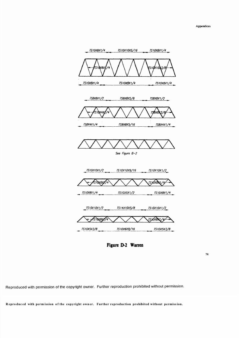
8/9/2019 Steel Roof Truss Optimization
http://slidepdf.com/reader/full/steel-roof-truss-optimization 88/98
Appendices
TS 10X8X 1/4 . TS10X 10X5/16 TS 10X8X 1/4
TS 10X8X1/4 TS10X8X1/4 TS 10X8X1/4
TS8X8X1/2 TS8X8X5/8 TS8X8X1/2
TS8X4X1/4 TS8X8X5/16 _________ TS8X4X1/4
/wwvw\ See Figure B- 2
TSI0XI0XJ/2 _________ TS 10X10 X9/16 TS10X10X1/2
TS 10X8X1/4 ____ TS1GX5X1/2 _________ TS10X8X1/4
TSI0XI0XJ/2 < TS14X10X5/8 < TSlOXlOXl/2^
TS 10X5X3 /8 __________ TS 10X6X 9/16 TS10X 5XJ/8
F igu re D -2 W ar ren
pro duc ed with perm ission o f the copyright own er. Further reproduction prohibited without permiss ion.

8/9/2019 Steel Roof Truss Optimization
http://slidepdf.com/reader/full/steel-roof-truss-optimization 89/98
Appendices
TS8X8X 5/16 TS8X8X3/8 TS8X8X5/16
TS8X4X1/4 TS8X4XI/4 : TS8X4X1/4
See Figure 8 -2
TS9X9X9/I6 TS9X9X5/8 TS9X9X9/16
\r S 9 X S X 5 Y 1 6 FX7X1Z
TS9X7X1/4 TS9X5X1/2 TS9X7X1/4
TS10XWX5/8 TS10X10X5/8 JS1 0X10X5/8
XjsmshjA^K
TS 10X6X3/8 TSTSI0X5X9/I6 _____________ TS 10X6X3/8
TS 12X1 2X5 /8 TS 12X12X5/8 TS 12X12X5/8
r ~ ~ - ^ l l S T ? X 6 X J / 2 '
TS 12X6X 1/2 TS12X6X5/8 TS12X6X1/2
Figure D-3 Cambered-Top Pra t t
79
pro duc ed with perm ission o f the copyright owner. Further reproduction prohibited without perm ission.
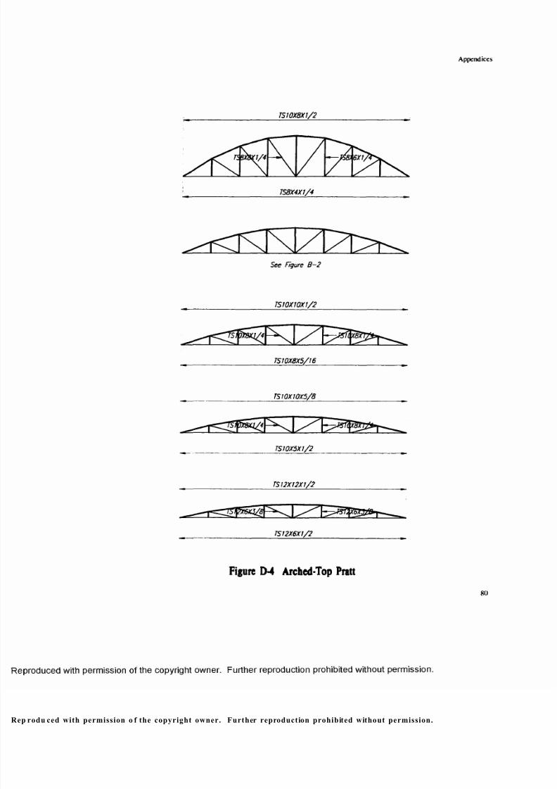
8/9/2019 Steel Roof Truss Optimization
http://slidepdf.com/reader/full/steel-roof-truss-optimization 90/98
Appendices
TS 10X8 X1/2
TS8X4X1/4
See Figure B -2
TS10X10X1/2
TS10X8X5/16
TS10X10X5/8
TS10X5X1/2
______________ TS12X12X1/2 __________________________ _
_______________ TS _12X6X1/2 ___________________________
Figure D-4 A rched-T op Pratt
80
p rodu ced with permission o f the copyright owner. Further reproduction prohibited without permission.
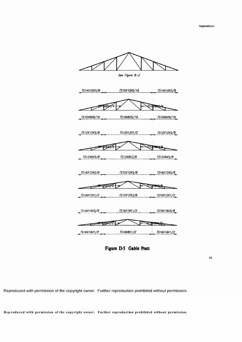
8/9/2019 Steel Roof Truss Optimization
http://slidepdf.com/reader/full/steel-roof-truss-optimization 91/98
Appendices
TS 14X1 0X5/8
See Figure B -2
TS10X10X9/16 TSI4X10X5/8
TS10X6X9/16 TS10X8X5/16 TS10X6X9/16
TS 12X12X5/8 TS 12X12X1/2 TS 12X12X 5/8
TS12X6X5/8 TS 12X8X5/8 TS12X6X5/8
TS 16X12X5/8 TS 12X12X5/8 TS 16X12X 5/8
TS16X12X1/2 TS 12X12X5/8 TS16X12X1/2
TS 16X16X5/8 TS16X16X1/2 TS 16X16X5 /8
TS 16X16X1/2 TS 16X8X1/2
i
1516X16X1/2
Figure D-5 Gable Pra t t
rodu ced with permission of the copyright owner. Further reproduction prohibited without permission.
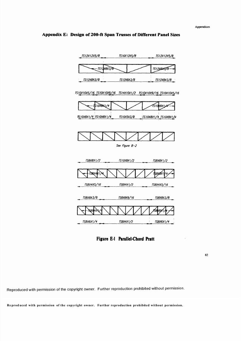
8/9/2019 Steel Roof Truss Optimization
http://slidepdf.com/reader/full/steel-roof-truss-optimization 92/98
Appendices
Appendix E: Design of 200-ft Span Trusses of Different Panel Sizes
TS12X12X5/8 TS 16X12X5/8 TS 12X12X5/8
TS1J/£X3/8— ~
TS 12X8X3/8 TS12X8XJ/8 TS 12X8X3 /8
TS10X10X5/16 , TS10X10X9/I6 TS14X10X1/2 TS10X10X9/16 , TS10X10X5/16
SIC (8X1.
TS 10X8X1/4 ITS 10X8X1/4 m TS10X5X3/8 _ \TS10X8Xl/4. TS 10X8X1/4
See Figure B -2
TS8X8 X1/2 TS 10X8X1/2 TS8X8X1/2
T S 8 X 4 X 5 / I 6 ________ TS8X4X1/2 TS8X4X5/16
T S 8 X 8 X 3 / 8 ___________ TS8X8X9/16 _______________ TS8X8X3/8
I 4.
TS8X6X1/4 TS8X4X1/2 TS8X6X1/4
Fig ure E-I Para l lel -Chord P ra t t
82
e prod uced with permission of the copyright owner. Further reproduction prohibited without permission.
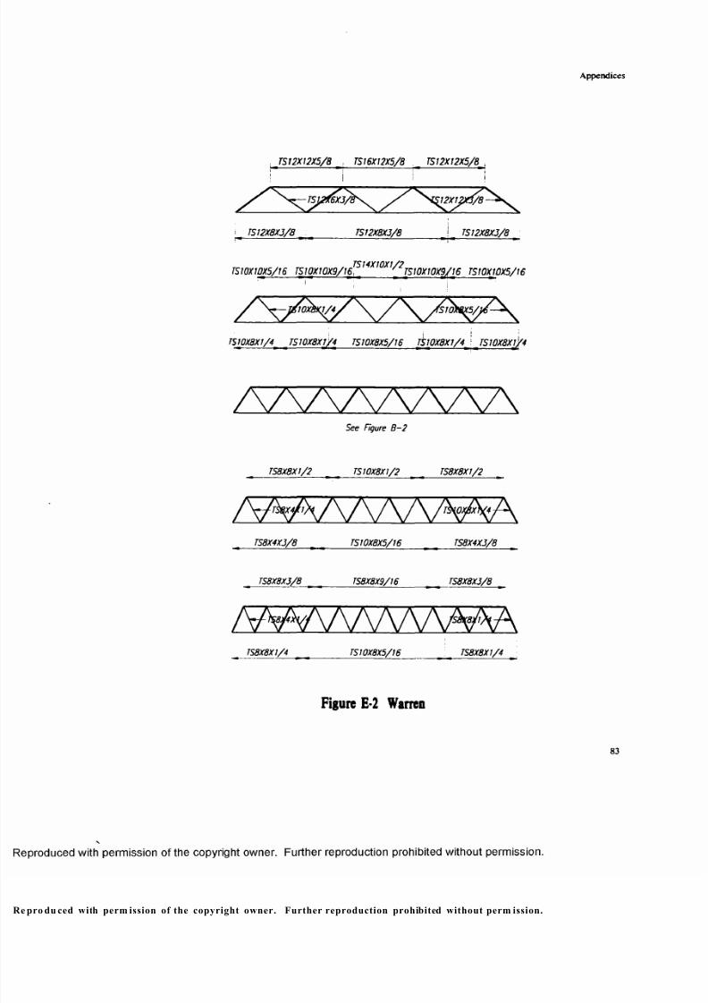
8/9/2019 Steel Roof Truss Optimization
http://slidepdf.com/reader/full/steel-roof-truss-optimization 93/98
Appendices
. TS12X12X5/8 . TS16X12X5/8 TS12X12X5/8
* TS 1 2X8X3/ 8 __________ TS12X8X3/8 _________ i TS 12X8 X3/8
TS10XWX 5/16 TSW XW X9/!61S,4XWX,/'2TSW XWX9/16 TSI0X10X5/16
! ;
TS 10X8X1/4' TS 10X8X1/4 TS 10X8X5/16 TS 1 0 X 8 X 1 /4 'JS 1 0X 8x f/4
M A / \ / W V \See Figure B -2
TS8X8X1/2 t | TS 10X8X1/2 _ _ TS8X8XI/2
M A A A A A A ^ ATS8X4X3/8 > TS 10X8X5/16 TS8X4 X3/8
TS8X8X3/8 _ _ TS8X8X9/I6 l TS8X8X3/8 _
/WVVXAAA/V^ATS8X8X1/ 4 _______ TS10X8X5/16 _________ : < TS8X8X1/4
Figu re E-2 W arren
83
pro du ced with perm ission of the copyright owner. Further reproduction prohibited without perm ission.
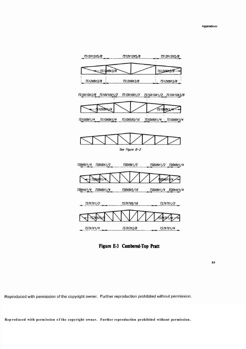
8/9/2019 Steel Roof Truss Optimization
http://slidepdf.com/reader/full/steel-roof-truss-optimization 94/98
Appendices
TS12X12X5/8 TS12X12X5/8 TS 12X12X5/8
TS13X8XJ/8
TS 12X8X3/8 TS12X8X3/8 TS12X8X3/8
TS! OX 10X 3/8 TS10X10X1/2 TS10X10X1/2 TS10X10X1/2 , TS10X10X3/8
S10X8X4/4 TS1M8XL
TS10X8X 1/4 TS10X8XJ/4 TS10X5X5/16 TS10X8X1/4 ' TS10X8X1/4
See Figure B- 2
TS8X8X1/41 TS8X8X1/2 < TS8X8X1/2 JS8X 8X1/2 JS8 X8 X1/4
- TS8X6K1/ E8X6X1Y4>
TS8X4XJ/4i TS8X8X1/4 TS8X8X5/16 JS 8X 8X I/4 TS8X4X1/4
TS7X7X1/2 TS7X7X9/16 TS7X7X1/2
TS7X7X1/4 TS7X7X3/8 TS7X7X1/4
Figure E-3 Cambered-Top Pra t t
8 4
p rod uced with perm ission o f the copyright owner. Further reproduction prohibited without permission .
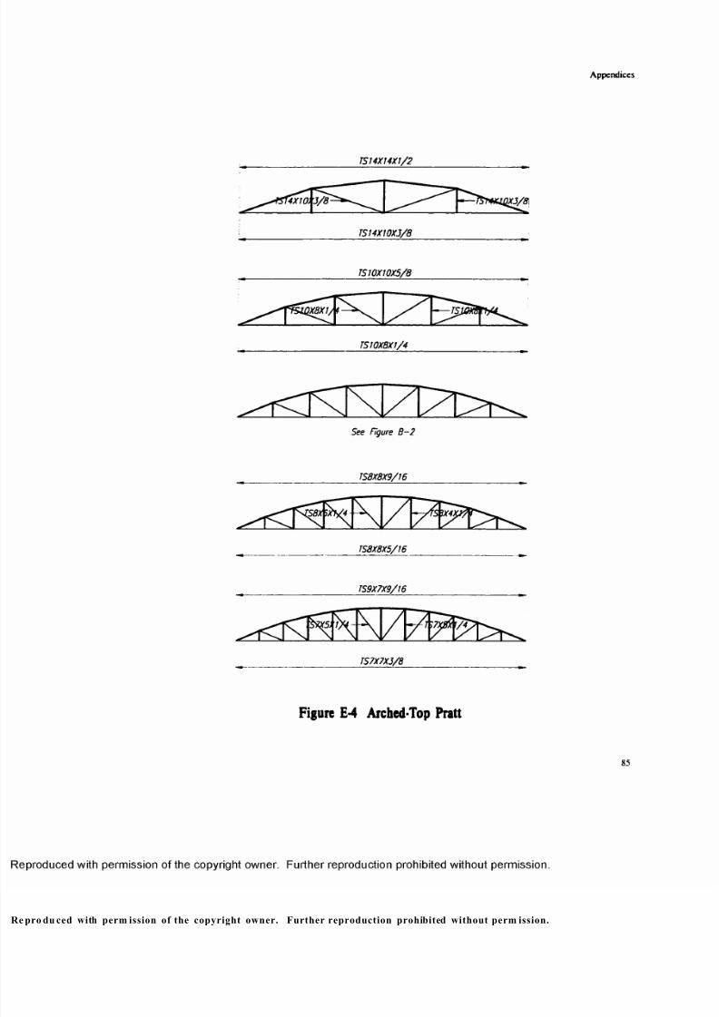
8/9/2019 Steel Roof Truss Optimization
http://slidepdf.com/reader/full/steel-roof-truss-optimization 95/98
Appendices
TS14X14X1/2
1x10X3/8
TS14X10XJ/8
TS 10X10X5/8
TS 10X8X1/4
See Figure B -2
TS8X8X9/16
TS8X8X5/16
TS9X7X9/16
TS7X7X3/8
Figure E-4 Arched-Top Pra t t
85
ro du ced with perm ission of the copyright owner. Further reproduction prohibited without perm ission.
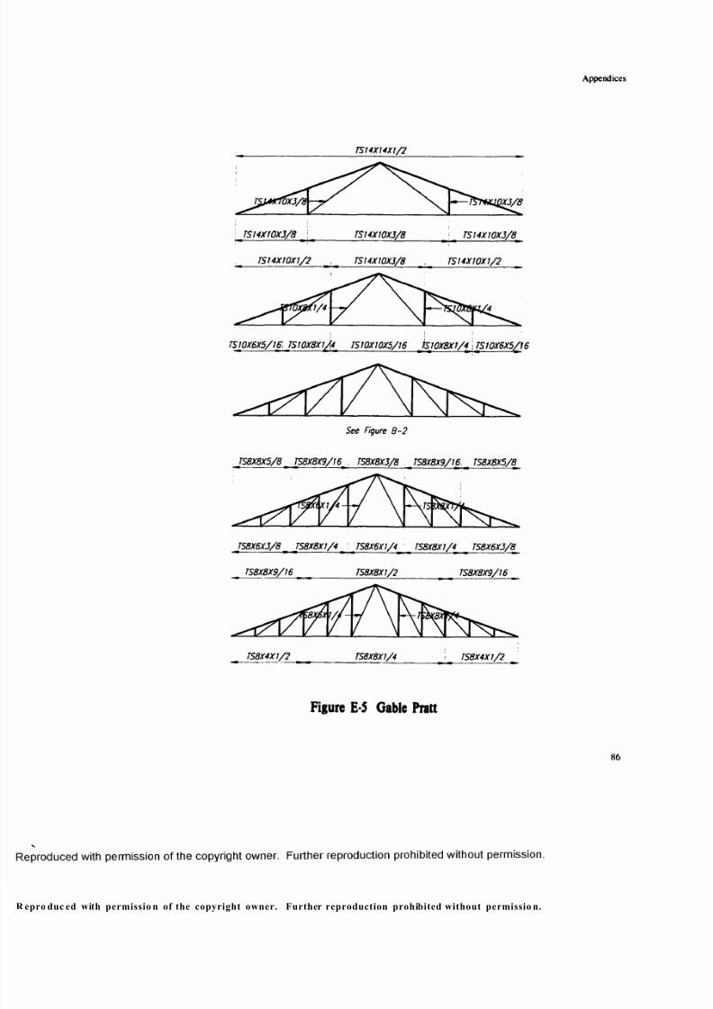
8/9/2019 Steel Roof Truss Optimization
http://slidepdf.com/reader/full/steel-roof-truss-optimization 96/98
Appendices
TS14X14X1/2
7X3/1 7X3/8
: TS14X10X3/8 \ : TS14X10X3/8
TS14XJ0X1 /2 TS14X10XJ/8 , TS74X10X1/2
TS 10X6 X5/18 TSI0X8 XI/4' TS10X10X5/16 TS 10X8X1/4 I TS70X6X5(16
See Figure B- 2
TS8X8X5/8 [ TS8X8X9/16 TS8X8X3/8 TS8X8X9/16 TS8X8X5/8
'1X1/4 TSV
TS8X6X3/8 TS8X8X1/4 : TS8X6Xl/4_ <TS8X8X1/4 TS8X6X3/8
TS8X8X9/16 ____ TS8X8X1/2 ______________ TS8X8X9/16
TS8X4X1/ ? TS8X8X1/4 i TS8X4X1/2
F i g u r e E -5 G a b l e P r a t t
86
pro duc ed with permissio n of the copyright owner. Further reproduction prohibited without permissio n.
8/9/2019 Steel Roof Truss Optimization
http://slidepdf.com/reader/full/steel-roof-truss-optimization 97/98
Reference
Reference
AISC. Manual o f Steel Construction/Ninth Edition.
Ambrose. James. Building Structures. John Wiley & Sons. Inc., 1993.
Ambrose, James. Design of Building Trusses. John Wiley & Sons, Inc., 1994
Griffin. C. W., and R. L. Fricklas. The Manual o f Low-Slope Roof Systems. McGraw-
Hill. 1996 & 1982.
Holgate. Alan. The Art in Structural Design. Clarendon Press, Oxford. 1986
MacDonald. Angus J. Structure and Architecture. Butterworth-Heinemann Ltd, 1994.
Mann. Thorbjoem. Building Economics for Architects. Van Nostrand Reinhold. NewYork. 1992.
Melaragno. Michele. Simplified Truss Design. Van Nostrand Reinhold Company.
Parker. Harry, and James Ambrose. Simplified Design o f Steel Structures. John Wiley& Sons. Inc.. 1990.
Parker. Harry, and James Ambrose. Simplified Engineering for Architects and Builders.
John Wiley & Sons. Inc.. 1994.
Salvadori. Mario and Robert Heller. Structure in Architecture. Prentice-Hall. Inc..
Englewood Cliffs. New Jersey. 1986.
Schueller. Wolfgang. The Design o f Building Structures. Prentice Hall. Inc.. 1995.
Torroja. Eduardo. Translated by J.J. Polivka and Milos Polivaka. Philosophy of
Structure . University of California Press. 1962.
pro duc ed with permissio n of the copyright owner. Further reproduction prohibited without perm ission.

8/9/2019 Steel Roof Truss Optimization
http://slidepdf.com/reader/full/steel-roof-truss-optimization 98/98
w
IMAGE EVALUATION TEST TARGET (Q A -3 )
<
£
150mm