steel-plate composite (sc) walls for safety …ahvarma/publications/p760.pdf · steel-plate...
TRANSCRIPT
Transactions, SMiRT 21, 6-11 November, 2011, New Delhi, India Div-VI: Paper ID# 760
1
STEEL-PLATE COMPOSITE (SC) WALLS FOR SAFETY RELATED NUCLEAR FACILITIES: DESIGN FOR IN-PLANE AND OUT-OF-PLANE DEMANDS Amit H. Varma1, Sanjeev R. Malushte2, Kadir Sener3, Zhichao Lai4 1Assoc. Pro., Bowen Lab., School of Civil Eng., Purdue Univ., W. Lafayette, IN. [email protected] 2Bechtel Fellow and Sr. Principal. Engineer, Bechtel Power Corp., Frederick, MD, USA, [email protected] 3Ph.D. Candidate, Bowen Lab., School of Civil Eng., Purdue Univ., W. Lafayette, IN. [email protected] 4Ph.D. Candidate, Bowen Lab., School of Civil Eng., Purdue Univ., W. Lafayette, IN. [email protected] E-mail of corresponding author: [email protected] ABSTRACT This paper presents a mechanics based model (MBM) for predicting the behavior of SC wall panels subjected to in-plane membrane forces (Sx, Sy, and Sxy). The model is verified using existing experimental results, and also using detailed nonlinear finite element models that overcome some of the limitations of the mechanics based model. The verified models (both MBM and finite element models) are used to develop an interaction surface in principal force space, which can be used for design. The models are further modified to account for the effects of out-of-plane moments (Mx, My, and Mxy) combined with the in-plane forces. Analytical results are used to develop a simple design approach that is based on the interaction surface in principal force space and can be implemented easily for SC wall sections. INTRODUCTION AND SCOPE
The design of conventional reinforced concrete (RC) walls for nuclear facilities is governed by the American Concrete Institute (ACI) code 349 [1]. However, there is no such code for the design of SC walls for safety-related nuclear facilities in the US. Over the past 25 years, Japanese researchers have conducted extensive experimental and computational research on the behavior and design of SC walls for nuclear facilities. In the past few years, S. Korean and US researchers have contributed to the knowledge and experimental database. The American Institute of Steel Construction (AISC) has formed a sub-committee to develop an appendix to AISC N690 [2] focusing on SC walls. This appendix is currently in development, and this paper presents some of the fundamental research that is being used to develop design specifications and associated commentary for SC walls. The implicit design philosophy is to design and detail the SC wall sections to prevent SC specific failure modes, for example, steel plate local buckling, interfacial shear failure between the steel plates and concrete infill, and section delamination or splitting failure through the concrete infill. Experimental results indicate that preventing these failure modes results in SC walls with excellent behavior and ductility for in-plane and out-of-plane forces and moments. This paper presents the design approach for SC walls subjected to combined in-plane forces (Sx, Sy, and Sxy) and out-of-plane moments (Mx, My, and Mxy).
Sy
T
ΔX
ΔY
SxSx
Sy
Sxy
Sxy
εx
εy
π/2- xy
Sy
Sxy
Sx
Sy
Sx
Sxy
εx
εy
(a)(b) (c)
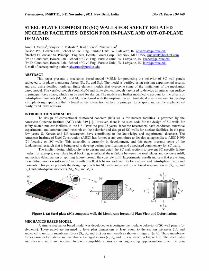
Figure 1. (a) Steel-plate (SC) composite wall, (b) Membrane forces, (c) Plan View and Deformations
MECHANICS BASED MODEL A simple mechanics based model was developed to investigate the in-plane behavior of SC wall panels (or elements). These panel are assumed to have plan dimensions at least equal to the section thickness (T), and subjected to uniform membrane forces (Sx, Sy, and Sxy) per unit length as shown in Figure 1(a, b). These membrane forces cause deformations and membrane averaged strains (εx, εy, and �xy) as shown in Figure 1(c). The steel plates and concrete infill are assumed to have compatible strains as an engineering approximation (over the plan

Transactions, SMiRT 21, 6-11 November, 2011, New Delhi, India Div-VI: Paper ID# 760
2
dimensions of at least T x T). This is typically achieved using shear connectors, for example, steel headed stud anchors that are stud-welded to the steel faceplates and anchored to the concrete. The size, length, and spacing of shear connectors are assumed to be adequate for providing strain compatibility. The membrane forces (Sx, Sy, and Sxy) can be used to compute a principal direction (θp) and associated principal forces (Sp1 and Sp2) as shown in Figure 2. Concrete cracking will occur when either or both principal forces (Sp1 and Sp2) become greater than the tensile cracking strength (Scr). Scr can be estimated using Equation 1, where the concrete cracking stress (f’t) is assumed to be 4√f’c in psi and shrinkage strain (εsh) effects are included [See Varma et al. [3] for additional discussion]. Cracking will occur perpendicular to the direction of the principal force causing it. The cracked concrete will potentially have orthotropic behavior with no stiffness in the principal force direction causing the cracks, and significant stiffness in the principal force direction perpendicular to it (if uncracked).
SxSx
Sy
Sy
Sxy
Sxy
θp
)2sin(SS2
)2cos(1S
2)2cos(1
S
)2sin(SS2
)2cos(1S
2)2cos(1
S
SSS2
)2tan(
pxyyp
xp
2p
pxyyp
xp
1p
yx
xyp
θ−θ+
+θ−
=
θ+θ−
+θ+
=
−=θ
(a) (b) (c)
Figure 2. Steel-plate (SC) composite wall: (a) Membrane Forces, (b) Principal Forces, (c) Equations
Scr =0.004 ′fc (psi)
Ec
− εsh
⎛
⎝⎜
⎞
⎠⎟ EcAc + EsAs[ ] Equation (1)
The cracked concrete can be assumed to have zero stiffness and strength perpendicular to the direction of cracking, which is a reasonable and conservative assumption. Japanese researchers (Ozaki et al. [4]) recommend that the stiffness in the direction parallel to the plane of cracking (E’c) can be assumed to be 70% of the uncracked stiffness (Ec). Thus, Figure 3 summarizes the stress-strain relationship for the cracked orthotropic concrete in principal stress space. It assumes that the principal strains (εp1 and εp2) are in the same direction as the principal stresses (cσp1 and cσp2) and the principal forces (Sp1 and Sp2).
θp
⎪⎭
⎪⎬
⎫
⎪⎩
⎪⎨
⎧εε
⎥⎥⎥
⎦
⎤
⎢⎢⎢
⎣
⎡′=
⎪⎭
⎪⎬
⎫
⎪⎩
⎪⎨
⎧σσ
000001or00001or0
E0
2p
1p
c2pc
1pc
x
y
Figure 3. Concrete Stress-Strain Relationship in Principal Stress Space
p1
p2
[ ]
[ ] [ ]ε−σ ×
⎥⎥⎥
⎦
⎤
⎢⎢⎢
⎣
⎡′×=
⎪⎭
⎪⎬
⎫
⎪⎩
⎪⎨
⎧
γεε
=⎪⎭
⎪⎬
⎫
⎪⎩
⎪⎨
⎧
τσσ
T00001or00001or0
ET]K[,where
K
c1
c
xy
y
x
c
c
yc
xc
Figure 4. Concrete Stress-Strain Relationship in x-y Stress Space

Transactions, SMiRT 21, 6-11 November, 2011, New Delhi, India Div-VI: Paper ID# 760
3
As shown in Figure 4, this stress-strain relationship can be recast in the x-y coordinate system using the stress and strain transformation matrices [T]σ and [T]ε. In Figure 4, [K]c is the cracked concrete stiffness matrix in x-y coordinate system. Figure 5 shows the stress-strain relationship for the steel faceplates, which is based on 2-D plane stress behavior. Es, ν, and [K]s are the elastic modulus, poisson ratio, and stiffness matrix for the steel plate.
⎥⎥⎥⎥
⎦
⎤
⎢⎢⎢⎢
⎣
⎡
ν−ν
ν
ν−=
⎪⎭
⎪⎬
⎫
⎪⎩
⎪⎨
⎧
γεε
=⎪⎭
⎪⎬
⎫
⎪⎩
⎪⎨
⎧
τσσ
2100
0101
1E]K[,where
]K[
2s
s
xy
y
x
s
s
ys
xsp1
p2
Figure 5. Stress Stress-Strain Relationship in x-y Stress Space
Sy
Sx
Sx
Sy
Sxy
Sxy
cσx Tc
cτTccτTc
cσy Tc
cσx Tc
cτTc
sσx tssτ ts
sσx ts
sτ ts
sσy ts
sσy ts
sσx tssτ ts
sσx ts
sτ ts
sσy ts
sσy ts
[ ]
[ ]⎪⎭
⎪⎬
⎫
⎪⎩
⎪⎨
⎧
+=⎪⎭
⎪⎬
⎫
⎪⎩
⎪⎨
⎧
γεε
∴
⎪⎭
⎪⎬
⎫
⎪⎩
⎪⎨
⎧
γεε
+=⎪⎭
⎪⎬
⎫
⎪⎩
⎪⎨
⎧
∴
⎪⎭
⎪⎬
⎫
⎪⎩
⎪⎨
⎧
τσσ
×+⎪⎭
⎪⎬
⎫
⎪⎩
⎪⎨
⎧
τσσ
×=⎪⎭
⎪⎬
⎫
⎪⎩
⎪⎨
⎧
−
xy
y
x1
ccss
xy
y
x
xy
y
x
ccss
xy
y
x
c
yc
xc
c
s
ys
xs
s
xy
y
x
SSS
]K[T]K[t2
]K[T]K[t2SSS
Tt2SSS
Figure 6. Free Body Diagram and Force Equilibrium for Steel-Plate Composite (SC) Section Figure 6 shows the free body diagram of the SC composite section subjected to membrane forces (Sx, Sy, and Sxy). It includes the stresses in the steel faceplate and the concrete infill, and the static force equilibrium equations relating the applied forces (Sx, Sy, and Sxy) to the section averaged strains (εx, εy, and �xy). As shown, the section averaged strains can be estimated using the applied forces and the steel and cracked concrete stiffness matrices [K]s and [K]c along with their respective areas. The section averaged strains (εx, εy, and γxy) can then be used to compute the stresses (cσx, cσy, and τc) in the concrete infill and the steel faceplates (sσx, sσy, and τs) using the equations in Figures 4 and 5, respectively. The stress transformation matrix [T]σ can then be used to compute the principal stresses (cσp1 and cσp2) in the concrete infill and the steel faceplates (sσp1 and sσp2). The steel faceplate principal stresses can be used to determine the occurrence of Von Mises yielding using Equation 2, where σVM is the Von Mises stress and yielding occurs when it becomes equal to the steel plate yield stress Fy.
σVM = σp12 + σp2
2 − σp1σp2 ≤ Fy Equation 2 The concrete behavior was assumed to be linear elastic (albeit with reduced stiffness and orthotropic behavior as shown in Figure 3). Therefore, the concrete minimum principal stress should be checked to ensure that it is still within the elastic range. For example, min{cσp1 , cσp2} ≥ -0.7 f’c , where 0.7f’c is assumed to represent the limit of linear elastic behavior from the concrete.
Transactions, SMiRT 21, 6-11 November, 2011, New Delhi, India Div-VI: Paper ID# 760
4
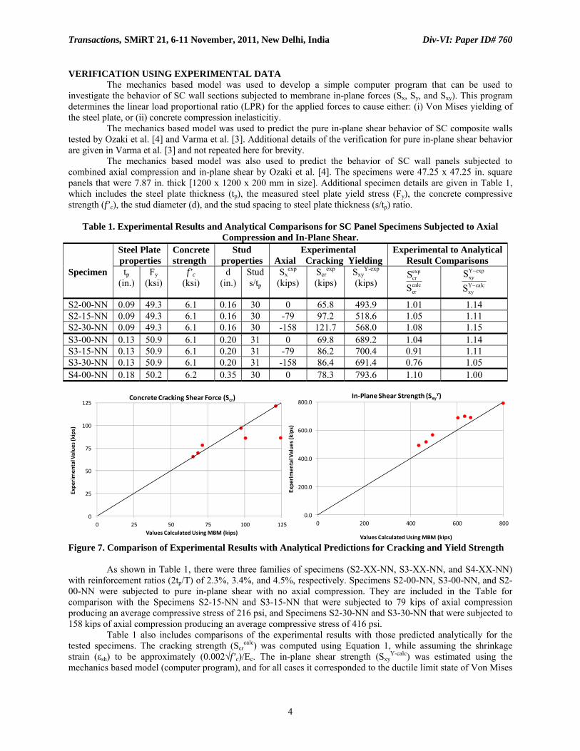
VERIFICATION USING EXPERIMENTAL DATA The mechanics based model was used to develop a simple computer program that can be used to investigate the behavior of SC wall sections subjected to membrane in-plane forces (Sx, Sy, and Sxy). This program determines the linear load proportional ratio (LPR) for the applied forces to cause either: (i) Von Mises yielding of the steel plate, or (ii) concrete compression inelasticitiy. The mechanics based model was used to predict the pure in-plane shear behavior of SC composite walls tested by Ozaki et al. [4] and Varma et al. [3]. Additional details of the verification for pure in-plane shear behavior are given in Varma et al. [3] and not repeated here for brevity. The mechanics based model was also used to predict the behavior of SC wall panels subjected to combined axial compression and in-plane shear by Ozaki et al. [4]. The specimens were 47.25 x 47.25 in. square panels that were 7.87 in. thick [1200 x 1200 x 200 mm in size]. Additional specimen details are given in Table 1, which includes the steel plate thickness (tp), the measured steel plate yield stress (Fy), the concrete compressive strength (f’c), the stud diameter (d), and the stud spacing to steel plate thickness (s/tp) ratio.
Table 1. Experimental Results and Analytical Comparisons for SC Panel Specimens Subjected to Axial Compression and In-Plane Shear.
Specimen
Steel Plate properties
Concrete strength
Stud properties
Experimental Axial Cracking Yielding
Experimental to AnalyticalResult Comparisons
tp (in.)
Fy (ksi)
f’c (ksi)
d (in.)
Stud s/tp
Sxexp
(kips) Scr
exp (kips)
SxyY-exp
(kips) Scr
exp
Scrcalc
SxyY−exp
SxyY−calc
S2-00-NN 0.09 49.3 6.1 0.16 30 0 65.8 493.9 1.01 1.14 S2-15-NN 0.09 49.3 6.1 0.16 30 -79 97.2 518.6 1.05 1.11 S2-30-NN 0.09 49.3 6.1 0.16 30 -158 121.7 568.0 1.08 1.15 S3-00-NN 0.13 50.9 6.1 0.20 31 0 69.8 689.2 1.04 1.14 S3-15-NN 0.13 50.9 6.1 0.20 31 -79 86.2 700.4 0.91 1.11 S3-30-NN 0.13 50.9 6.1 0.20 31 -158 86.4 691.4 0.76 1.05 S4-00-NN 0.18 50.2 6.2 0.35 30 0 78.3 793.6 1.10 1.00
0
25
50
75
100
125
0 25 50 75 100 125
Expe
rimen
tal Value
s (kips)
Values Calculated Using MBM (kips)
Concrete Cracking Shear Force (Scr)
0.0
200.0
400.0
600.0
800.0
0 200 400 600 800
Expe
rimen
tal Value
s (kips)
Values Calculated Using MBM (kips)
In‐Plane Shear Strength (SxyY)
Figure 7. Comparison of Experimental Results with Analytical Predictions for Cracking and Yield Strength As shown in Table 1, there were three families of specimens (S2-XX-NN, S3-XX-NN, and S4-XX-NN) with reinforcement ratios (2tp/T) of 2.3%, 3.4%, and 4.5%, respectively. Specimens S2-00-NN, S3-00-NN, and S2-00-NN were subjected to pure in-plane shear with no axial compression. They are included in the Table for comparison with the Specimens S2-15-NN and S3-15-NN that were subjected to 79 kips of axial compression producing an average compressive stress of 216 psi, and Specimens S2-30-NN and S3-30-NN that were subjected to 158 kips of axial compression producing an average compressive stress of 416 psi. Table 1 also includes comparisons of the experimental results with those predicted analytically for the tested specimens. The cracking strength (Scr
calc) was computed using Equation 1, while assuming the shrinkage strain (εsh) to be approximately (0.002√f’c)/Ec. The in-plane shear strength (Sxy
Y-calc) was estimated using the mechanics based model (computer program), and for all cases it corresponded to the ductile limit state of Von Mises
Transactions, SMiRT 21, 6-11 November, 2011, New Delhi, India Div-VI: Paper ID# 760
5
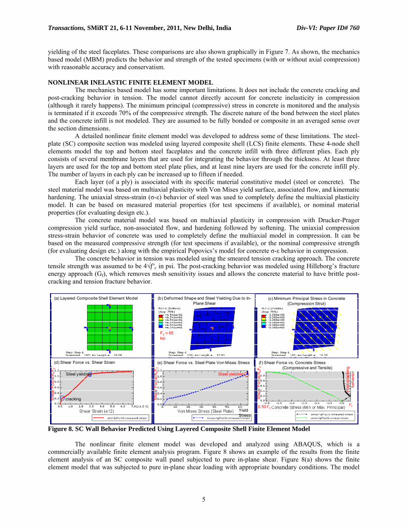
yielding of the steel faceplates. These comparisons are also shown graphically in Figure 7. As shown, the mechanics based model (MBM) predicts the behavior and strength of the tested specimens (with or without axial compression) with reasonable accuracy and conservatism. NONLINEAR INELASTIC FINITE ELEMENT MODEL The mechanics based model has some important limitations. It does not include the concrete cracking and post-cracking behavior in tension. The model cannot directly account for concrete inelasticity in compression (although it rarely happens). The minimum principal (compressive) stress in concrete is monitored and the analysis is terminated if it exceeds 70% of the compressive strength. The discrete nature of the bond between the steel plates and the concrete infill is not modeled. They are assumed to be fully bonded or composite in an averaged sense over the section dimensions. A detailed nonlinear finite element model was developed to address some of these limitations. The steel-plate (SC) composite section was modeled using layered composite shell (LCS) finite elements. These 4-node shell elements model the top and bottom steel faceplates and the concrete infill with three different plies. Each ply consists of several membrane layers that are used for integrating the behavior through the thickness. At least three layers are used for the top and bottom steel plate plies, and at least nine layers are used for the concrete infill ply. The number of layers in each ply can be increased up to fifteen if needed. Each layer (of a ply) is associated with its specific material constitutive model (steel or concrete). The steel material model was based on multiaxial plasticity with Von Mises yield surface, associated flow, and kinematic hardening. The uniaxial stress-strain (σ-ε) behavior of steel was used to completely define the multiaxial plasticity model. It can be based on measured material properties (for test specimens if available), or nominal material properties (for evaluating design etc.). The concrete material model was based on multiaxial plasticity in compression with Drucker-Prager compression yield surface, non-associated flow, and hardening followed by softening. The uniaxial compression stress-strain behavior of concrete was used to completely define the multiaxial model in compression. It can be based on the measured compressive strength (for test specimens if available), or the nominal compressive strength (for evaluating design etc.) along with the empirical Popovics’s model for concrete σ-ε behavior in compression. The concrete behavior in tension was modeled using the smeared tension cracking approach. The concrete tensile strength was assumed to be 4√f’c in psi. The post-cracking behavior was modeled using Hilleborg’s fracture energy approach (Gf), which removes mesh sensitivity issues and allows the concrete material to have brittle post-cracking and tension fracture behavior.
cracking
Steel yielding
She
ar F
orce
/AsF
y
Steel yielding
Yield Stress
0.50 f’c f’t
She
ar F
orce
/AsF
y
(a) Layered Composite Shell Element Model (b) Deformed Shape and Steel Yielding Due to In-Plane Shear
Fy = 65 ksi
(c) Minimum Principal Stress in Concrete (Compression Strut)
(d) Shear Force vs. Shear Strain (e) Shear Force vs. Steel Plate Von Mises Stress (f ) Shear Force vs. Concrete Stress (Compressive and Tensile)
She
ar F
orce
/AsF
y
Pos
t-cra
ckin
g be
havi
or
Figure 8. SC Wall Behavior Predicted Using Layered Composite Shell Finite Element Model The nonlinear finite element model was developed and analyzed using ABAQUS, which is a commercially available finite element analysis program. Figure 8 shows an example of the results from the finite element analysis of an SC composite wall panel subjected to pure in-plane shear. Figure 8(a) shows the finite element model that was subjected to pure in-plane shear loading with appropriate boundary conditions. The model
Transactions, SMiRT 21, 6-11 November, 2011, New Delhi, India Div-VI: Paper ID# 760
6
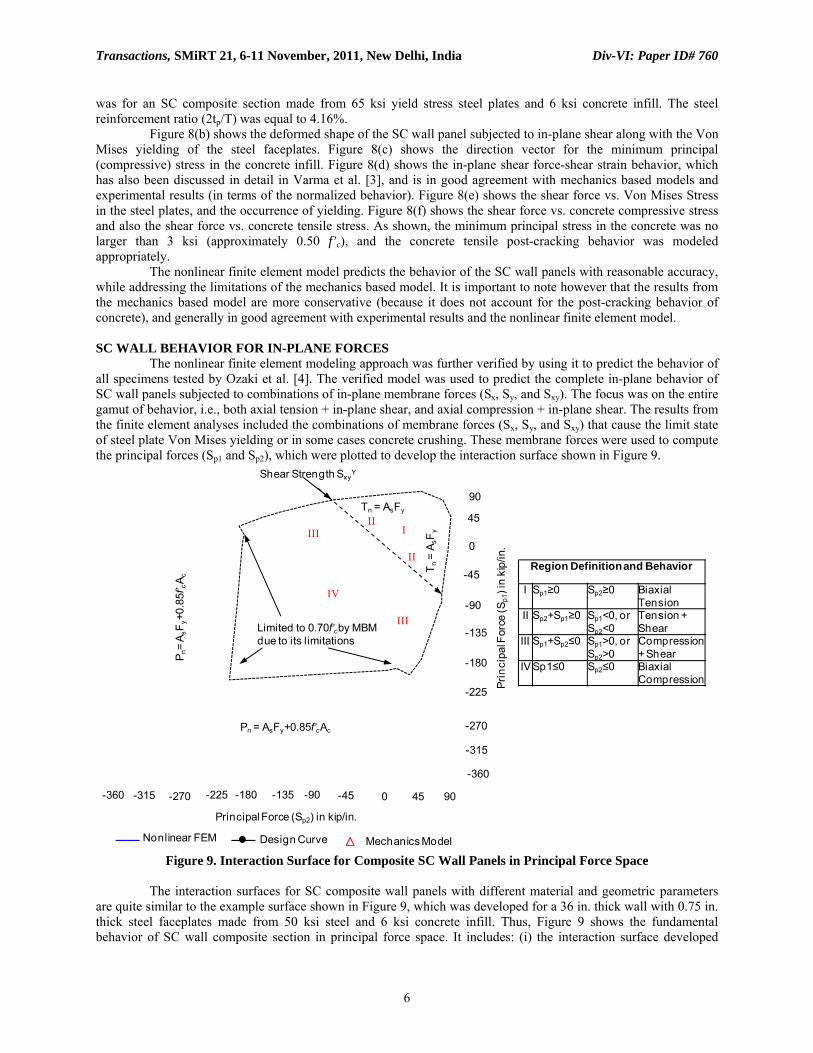
was for an SC composite section made from 65 ksi yield stress steel plates and 6 ksi concrete infill. The steel reinforcement ratio (2tp/T) was equal to 4.16%. Figure 8(b) shows the deformed shape of the SC wall panel subjected to in-plane shear along with the Von Mises yielding of the steel faceplates. Figure 8(c) shows the direction vector for the minimum principal (compressive) stress in the concrete infill. Figure 8(d) shows the in-plane shear force-shear strain behavior, which has also been discussed in detail in Varma et al. [3], and is in good agreement with mechanics based models and experimental results (in terms of the normalized behavior). Figure 8(e) shows the shear force vs. Von Mises Stress in the steel plates, and the occurrence of yielding. Figure 8(f) shows the shear force vs. concrete compressive stress and also the shear force vs. concrete tensile stress. As shown, the minimum principal stress in the concrete was no larger than 3 ksi (approximately 0.50 f’c), and the concrete tensile post-cracking behavior was modeled appropriately. The nonlinear finite element model predicts the behavior of the SC wall panels with reasonable accuracy, while addressing the limitations of the mechanics based model. It is important to note however that the results from the mechanics based model are more conservative (because it does not account for the post-cracking behavior of concrete), and generally in good agreement with experimental results and the nonlinear finite element model. SC WALL BEHAVIOR FOR IN-PLANE FORCES The nonlinear finite element modeling approach was further verified by using it to predict the behavior of all specimens tested by Ozaki et al. [4]. The verified model was used to predict the complete in-plane behavior of SC wall panels subjected to combinations of in-plane membrane forces (Sx, Sy, and Sxy). The focus was on the entire gamut of behavior, i.e., both axial tension + in-plane shear, and axial compression + in-plane shear. The results from the finite element analyses included the combinations of membrane forces (Sx, Sy, and Sxy) that cause the limit state of steel plate Von Mises yielding or in some cases concrete crushing. These membrane forces were used to compute the principal forces (Sp1 and Sp2), which were plotted to develop the interaction surface shown in Figure 9.
Limited to 0.70f’cby MBM due to its limitations
P n=
A sF y
+0.8
5f’ cA
c
Pn = AsFy+0.85f’cAc
T n=
A sF y
Tn = AsFy
III
III
IV
III
II
Shear Strength SxyY
Principal Force (Sp2) in kip/in.
Region Definition and Behavior
I Sp1≥0 Sp2≥0 Biaxial Tension
II Sp2+Sp1≥0 Sp1<0, orSp2<0
Tension + Shear
III Sp1+Sp2≤0 Sp1>0, or Sp2>0
Compression + Shear
IV Sp1≤0 Sp2≤0 Biaxial Compression
Nonlinear FEM Design Curve Mechanics Model
90
45
0
-45
-90
-135
-180
-225
-270
-315
-360
Prin
cipa
l For
ce (S
p1) i
n ki
p/in
.
-360 -315 -270 -225 -180 -135 -90 -45 0 45 90
Figure 9. Interaction Surface for Composite SC Wall Panels in Principal Force Space
The interaction surfaces for SC composite wall panels with different material and geometric parameters are quite similar to the example surface shown in Figure 9, which was developed for a 36 in. thick wall with 0.75 in. thick steel faceplates made from 50 ksi steel and 6 ksi concrete infill. Thus, Figure 9 shows the fundamental behavior of SC wall composite section in principal force space. It includes: (i) the interaction surface developed

Transactions, SMiRT 21, 6-11 November, 2011, New Delhi, India Div-VI: Paper ID# 760
7
using nonlinear finite element models that can explicitly account for the concrete material inelasticity (in compression) and brittle post-cracking behavior in tension, (ii) the interaction surface developed using the mechanics based model that limits the concrete minimum principal stress to 0.70f’c and the steel plates to Von Mises yielding, and (iii) the interaction surface recommended for design. As expected, the interaction surface predicted using the nonlinear finite element analyses is much larger than that predicted by the mechanics based model, which is limited to the elastic range (stress less than 0.70f’c) of behavior for concrete in compression. As shown, there are four distinct regions of behavior: (i) region I corresponds to the primarily to the state of biaxial tension, (ii) region II corresponds to the state of axial tension + in-plane shear, (iii) region III corresponds to the state of axial compression + in-plane shear, and (iv) region IV corresponds to the state of biaxial compression. The anchor points marking the transition from one region to the next can be computed using simple equations for the tension strength (Tn = AsFy), in-plane shear strength (Vn
in = SxyY), and compression strength (Pn =
AsFy+0.85f’cAc) of the SC composite section. A simple design interaction curve is developed by connecting these anchor points with straight line segments. As shown, the design curve is quite conservative with respect to the nonlinear finite element analysis curve, and also conservative with respect to the mechanics based model except for some portions of regions III and IV, where the mechanics model was severely limited by the concrete behavior in compression. SC WALL BEHAVIOR FOR IN-PLANE FORCES + OUT-OF-PLANE MOMENTS The nonlinear finite element modeling approach was used to evaluate the behavior of SC wall panels subjected to combinations of in-plane forces and out-of-plane bending moments (Mx, My, and Mxy). The finite element models were similar to those developed earlier for the in-plane forces, with the exception that the number of layers in the steel plies were increase to at least five, and the number of layers in the concrete ply were increase to at least fifteen. The finite element models were used to evaluate the effect of different force combinations like axial compression + bending moment (Sx and Mx), in-plane shear + bending moment (Sxy and Mx), etc. The mechanics based model was also modified to include several layers through the composite section, and three more deformations at the central layer (εx, εy, and γxy) corresponding to the moments (Mx, My, and Mxy). The strains in each layer (i) were assessed using the six strains at the central layer (εx, εy, γxy, φx, φy, and φxy) and the distance from it (yi). These strains were then used to compute the principal direction (θp), principal strains (εp1 and εp2). The concrete cracking direction for each layer was slightly different depending on the combination of applied forces. The principal strains were used to compute the corresponding stresses in the concrete or steel layers using the equations in Figures 4 and 5. The stresses were integrated through the cross-section, and force equilibrium was established for the applied combinations of forces. A computer program was developed to solve the force and moment equilibrium equations iteratively, i.e., to determine the strains (εx, εy, γxy, φx, φy, and φxy) associated with the applied forces (Sx, Sy, Sxy, Mx, My, and Mxy). These strains were used to determine the principal direction, strains, and stresses in each layer through the SC composite section. The steel plate stresses were used to establish Von Mises yielding, and the concrete layer minimum principal stress was checked to limit behavior and stresses in the elastic range (stress less than 0.70 f’c).
The results from the nonlinear finite element analyses and the computer program compared reasonably with each other, particularly when the failure limit state was governed by Von Mises yielding of the steel plates. As expected, for situations where the concrete behavior in compression was the governing limit state, the mechanics based model was more conservative with respect to the finite element analyses. For example, Figure 10 shows the in-plane shear vs. bending moment (Sxy-Mx) interaction for the SC composite section used in Figure 10. The figure includes the predictions from the finite element model and the mechanics based model. As expected, the mechanics based model is slightly conservative with respect to the nonlinear finite element analyses.
Figure 10. Moment – Shear Interaction for SC Wall
1.0
0.8
0.6
0.4
0.2
0.2 0.60.4 0.8 1.0
Bend
ing
Mom
ent M
x/ (
A sF y
T)
In-Plane Shear Force Sxy / (As Fy)
FEM Results
Design Approach

Transactions, SMiRT 21, 6-11 November, 2011, New Delhi, India Div-VI: Paper ID# 760
8
DESIGN FOR COMBINED FORCES AND MOMENTS The results from the finite element analyses and the mechanics based models were used to develop a simple design approach for evaluating SC wall sections subjected to combined in-plane forces (Sx, Sy, Sxy) and out-of-plane moments (Mx, My, Mxy). The design approach considers the SC composite section in two notional halves (top and bottom) that are subjected primarily to membrane forces (Sx’, Sy’, and Sxy’) that can be calculated using the in-plane forces and out-of-plane moment demands using an assumed arm length (for example, 0.90 T). These membrane forces (Sx’, Sy’, and Sxy’) can be used to compute principal membrane forces (Sp1 and Sp2) for each of the two notional halves. These principal forces (Sp1 and Sp2) must lie within the interaction surface shown in Figure 1 for both notional halves. The interaction surface shown in Figure 11 was developed considering the results from the nonlinear finite element analyses and mechanics based models conservatively as shown in Figure 9. The conservatism of this approach was evaluated using several case studies and force-moment interactions. For example, Figure 10 includes the bending moment – in-plane shear force interaction predicted by the design approach and demonstrates it to be conservative than both the mechanics based model and the finite element results.
Region Definition and Behavior
I Sp1≥0 Sp2≥0 Biaxial Tension
II Sp2+Sp1≥0 Sp1<0, orSp2<0
Tension + Shear
III Sp1+Sp2≤0 Sp1>0, or Sp2>0
Compression + Shear
IV Sp1≤0 Sp2≤0 Biaxial Compression
Pure Tension(0, Tci)
Pure Compression(0, -Pci)
Biaxial Tension(Tci, Tci)
Pure Compression(-Pci, 0)
Pure Shear(Vci, -Vci)
Biaxial Compression(-Pci, -Pci)
Pure Tension(Tci , 0)
Pure Shear(-Vci, Vci)
Principal Force 1 (Sp1, kip/ft)
Prin
cipa
l For
ce 2
(Sp2
, kip
/ft)
Tci = 0.5 x Design Tension Strength (kip/ft)Vci = 0.5 x Design In-Plane Shear Strength (kip/ft)Pci = 0.5 x Design Compression Strength (kip/ft)
III
III
IV
III
II
Figure 11. Interaction Surface in Principal Force Space for Each Notional Half
SUMMARY AND CONCLUSIONS This paper presents a simple design approach for SC walls subjected to combined in-plane forces and out-of-plane moment demands. The approach is applicable to SC Walls that are detailed to prevent SC specific failure modes like local buckling, interfacial shear failure, etc. The design approach has been developed using the results of mechanics based models verified using experimental results and detailed nonlinear finite element analyses. The design approach consists of developing an interaction surface in principal force space (Sp1 and Sp2), and using it to check each notional half of the SC wall section subjected to combined in-plane forces and out-of-plane demands. ACKNOWLEDGMENTS The research presented in this paper was partially funded by Purdue University and also partially funded by Bechtel Corp. All findings presented in the paper are strictly those of the authors. REFERENCES [1] ACI 349 (2006), “Code Requirements for Nuclear Safety-Related Concrete Structures and Commentary,”
American Concrete Institute, Farmington Hills, MI. [2] AISC N690 (2006), “Specification for Safety-Related Steel Structures for Nuclear Facilities,” AISC, Chicago,
IL. [3] Varma, A.H., Zhang, K., Chi, H., Booth, P. and Baker, T. (2011). “In-Plane Shear Behavior of SC Composite
Walls: Theory vs. Experiment.” Proceedings of the 21st IASMiRT Conference, SMiRT 21, Paper ID #764. Nov. 6-11, New Delhi, India.
[4] Ozaki, M., Akita, S., Oosuga, H., Nakayama, T., Adachi, N. (2004). "Study on Steel Plate Reinforced Concrete Panels Subjected to Cyclic In-Plane Shear." Nuclear Engineering and Design, Vol. 228, pp. 225-244.