steel cord - vulcanized splice
TRANSCRIPT
VULCANIZED SPLICINGFOR STEEL CORD
CONVEYOR BELTSONE-STEP METHODTWO-STEP METHOD
1
VULCANIZING SPLICINGFOR STEEL CORD CONVEYOR BELTS
CONTENTS
INTRODUCTION
2
STANDARD PATTERN
2
SPLICING MATERIALS
4
SPLICING PROCEDURE
A. Preparation 5
B. Forming 6
C. Vulcanizing 13
D. Finishing 15
E. Precautions 15
2
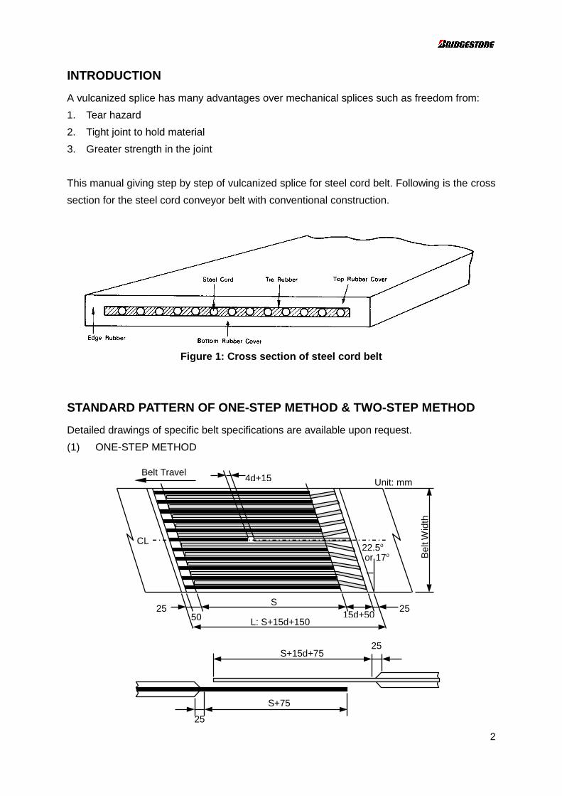
INTRODUCTION
A vulcanized splice has many advantages over mechanical splices such as freedom from:
1. Tear hazard
2. Tight joint to hold material
3. Greater strength in the joint
This manual giving step by step of vulcanized splice for steel cord belt. Following is the cross
section for the steel cord conveyor belt with conventional construction.
Figure 1: Cross section of steel cord belt
STANDARD PATTERN OF ONE-STEP METHOD & TWO-STEP METHOD
Detailed drawings of specific belt specifications are available upon request.
(1) ONE-STEP METHOD
25S+15d+75
S+75
25
4d+15
502525
S15d+50
L: S+15d+150
Bel
t Wid
th
Unit: mmBelt Travel
CL22.5o
or 17o

3
(2) TWO-STEP METHOD
Step Length (S) Except heat resistant rubber
Steel cord d S Steel cord d S
construction Steel cord dia. Step length construction Steel cord dia. Step length
(mm) (mm) (mm) (mm)
3+9+15 2.3-2.5 300 7 x 7 2.5 250
2.6-3.0 350 2.6-3.1 300
3.1-3.4 400 3.2-3.4 350
3.5-3.6 450 3.5-3.8 400
3.7-3.9 500 3.9-4.1 450
4.0-4.3 550 4.2-4.6 500
4.4-4.7 600 4.7-5.2 550
4.8-4.9 650
5.0 700
Belt
CL
25 25SS
15d+50
15d+5L:2S+34d+165
Belt
Wid
th
Unit: mm4d+15
22.5o
or 17o
2S+19d+65
2S+19d+65
25
25
Tie Gum (W25)Cement (W90)
Steel CordCover Gum (W10)
Cover Gum (W10)
4
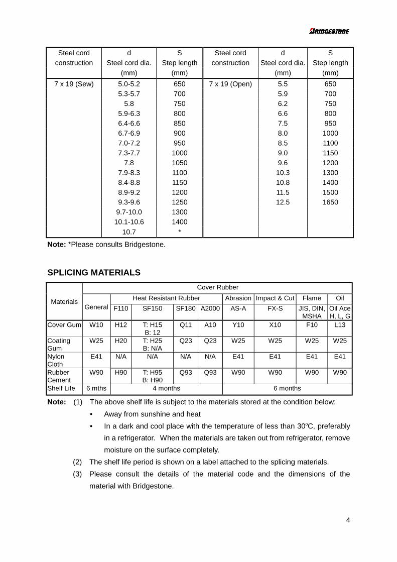
Steel cord d S Steel cord d S
construction Steel cord dia. Step length construction Steel cord dia. Step length
(mm) (mm) (mm) (mm)
7 x 19 (Sew) 5.0-5.2 650 7 x 19 (Open) 5.5 650
5.3-5.7 700 5.9 700
5.8 750 6.2 750
5.9-6.3 800 6.6 800
6.4-6.6 850 7.5 950
6.7-6.9 900 8.0 1000
7.0-7.2 950 8.5 1100
7.3-7.7 1000 9.0 1150
7.8 1050 9.6 1200
7.9-8.3 1100 10.3 1300
8.4-8.8 1150 10.8 1400
8.9-9.2 1200 11.5 1500
9.3-9.6 1250 12.5 1650
9.7-10.0 1300
10.1-10.6 1400
10.7 *
Note: *Please consults Bridgestone.
SPLICING MATERIALS
Cover Rubber
Heat Resistant Rubber Abrasion Impact & Cut Flame OilMaterialsGeneral F110 SF150 SF180 A2000 AS-A FX-S JIS, DIN,
MSHAOil AceH, L, G
Cover Gum W10 H12 T: H15B: 12
Q11 A10 Y10 X10 F10 L13
CoatingGum
W25 H20 T: H25B: N/A
Q23 Q23 W25 W25 W25 W25
NylonCloth
E41 N/A N/A N/A N/A E41 E41 E41 E41
RubberCement
W90 H90 T: H95B: H90
Q93 Q93 W90 W90 W90 W90
Shelf Life 6 mths 4 months 6 months
Note: (1) The above shelf life is subject to the materials stored at the condition below:
• Away from sunshine and heat
• In a dark and cool place with the temperature of less than 30oC, preferably
in a refrigerator. When the materials are taken out from refrigerator, remove
moisture on the surface completely.
(2) The shelf life period is shown on a label attached to the splicing materials.
(3) Please consult the details of the material code and the dimensions of the
material with Bridgestone.
SPLICING PROCEDURE
A. PREPARATION
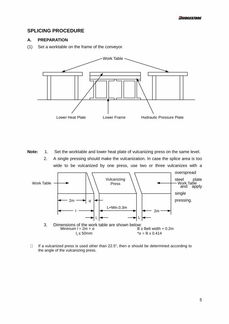
(1) Set a worktable on the frame of the conveyor.
Note: 1.
2. A
w
3. D
Work Table
∗ If a vulcathe angle
Lower Heat Plate
Set the worktable and low
single pressing should
ide to be vulcanized b
imensions of the work ta
l
l1
2m α
Minimum l = 2m + α l1 ≤ 50mm
nized press is used other th of the vulcanizing press.
Lower Frame
er heat plate of vulc
make the vulcanizati
y one press, use
ble are shown below
l1
L+Min.0.3m
VulcanizingPress
B*α
an 22.5o, then α shou
Hydraulic Pressure Plate
Work Table
5
anizing press on the same level.
on. In case the splice area is too
two or three vulcanizes with a
overspread
steel plate
and apply
single
pressing.
:
Work Table
2m
≥ Belt width + 0.2m = B x 0.414
ld be determined according to
6
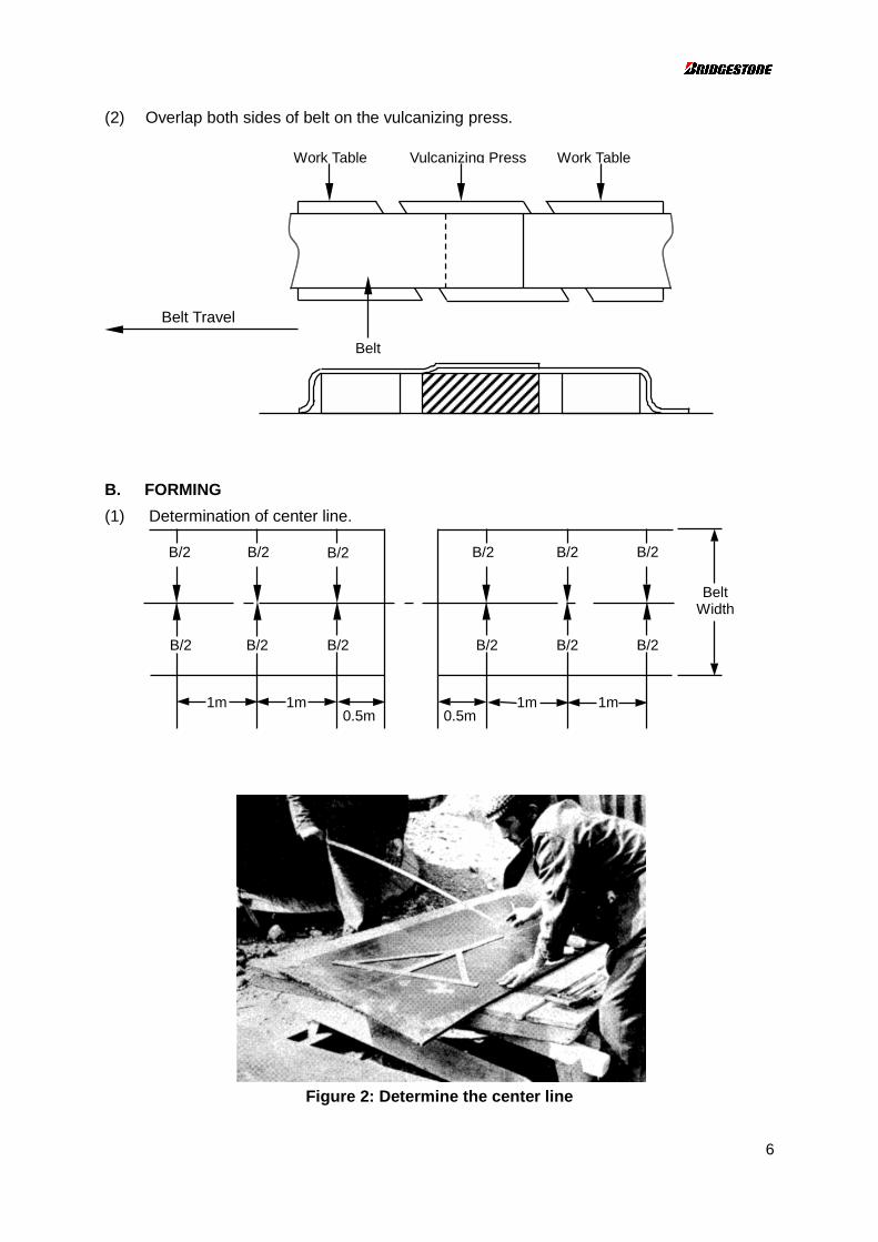
(2) Overlap both sides of belt on the vulcanizing press.
B. FORMING
(1) Determination of center line.
Figure 2: Determine the center line
Belt
Vulcanizing PressWork Table Work Table
Belt Travel
1m 1m0.5m
B/2
B/2
0.5m1m 1m
BeltWidth
B/2
B/2 B/2
B/2
B/2 B/2 B/2
B/2B/2B/2
7
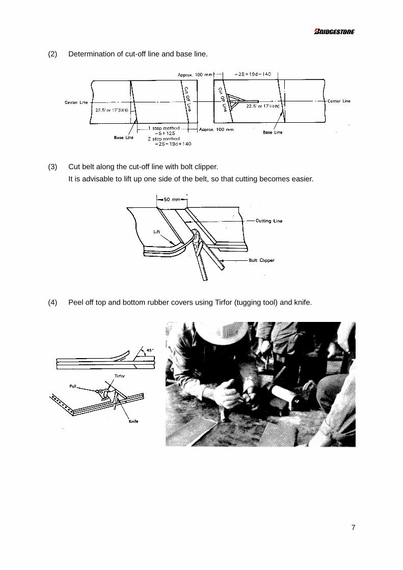
(2) Determination of cut-off line and base line.
(3) Cut belt along the cut-off line with bolt clipper.
It is advisable to lift up one side of the belt, so that cutting becomes easier.
(4) Peel off top and bottom rubber covers using Tirfor (tugging tool) and knife.
8
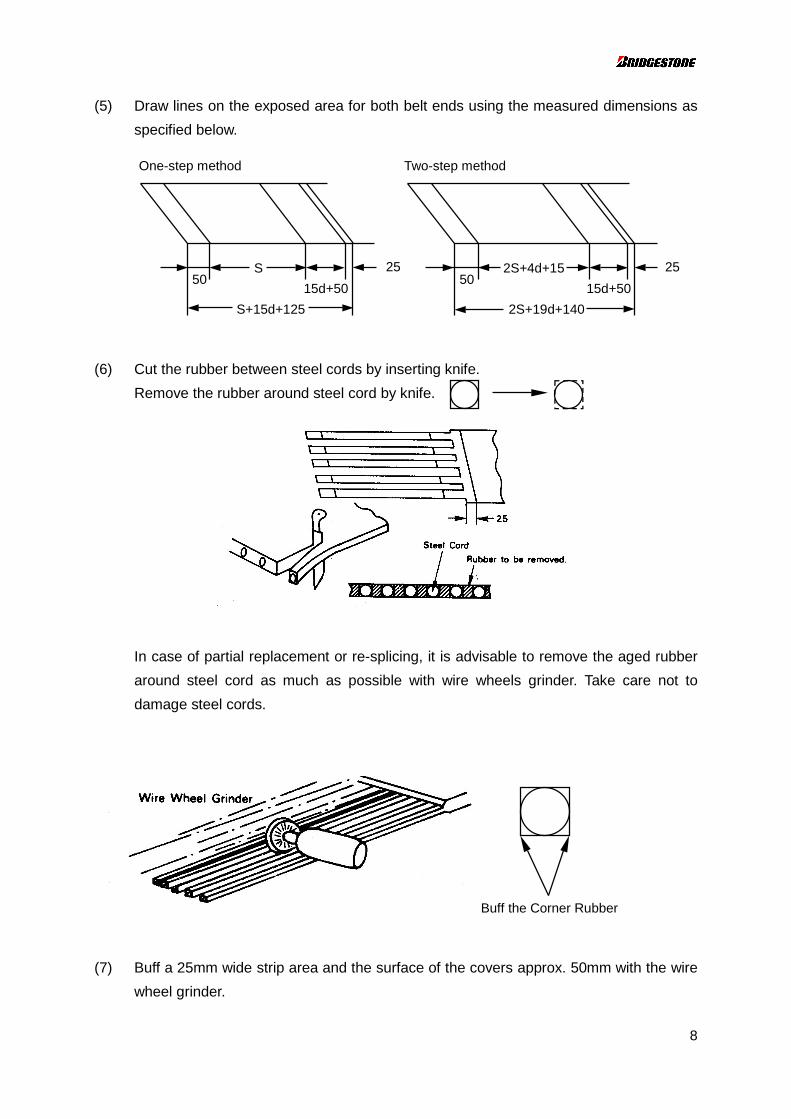
(5) Draw lines on the exposed area for both belt ends using the measured dimensions as
specified below.
(6) Cut the rubber between steel cords by inserting knife.
Remove the rubber around steel cord by knife.
In case of partial replacement or re-splicing, it is advisable to remove the aged rubber
around steel cord as much as possible with wire wheels grinder. Take care not to
damage steel cords.
(7) Buff a 25mm wide strip area and the surface of the covers approx. 50mm with the wire
wheel grinder.
Buff the Corner Rubber
25
S+15d+125
S50
15d+50
25
2S+19d+140
2S+4d+1550
15d+50
One-step method Two-step method
9
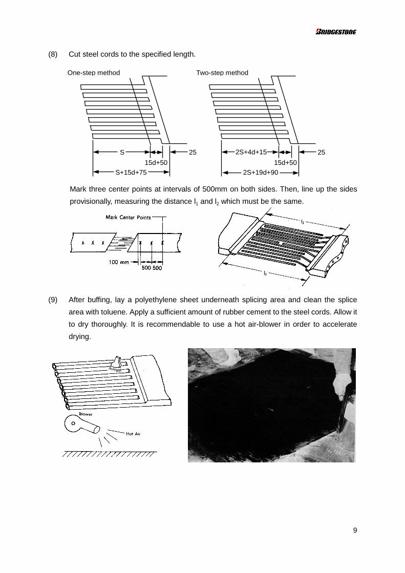
(8) Cut steel cords to the specified length.
Mark three center points at intervals of 500mm on both sides. Then, line up the sides
provisionally, measuring the distance l1 and l2 which must be the same.
(9) After buffing, lay a polyethylene sheet underneath splicing area and clean the splice
area with toluene. Apply a sufficient amount of rubber cement to the steel cords. Allow it
to dry thoroughly. It is recommendable to use a hot air-blower in order to accelerate
drying.
S+15d+75
S
15d+50
25
One-step method
2S+19d+90
2S+4d+15
15d+50
25
Two-step method
10
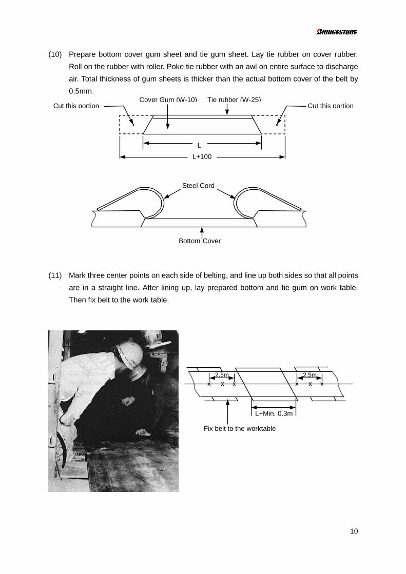
(10) Prepare bottom cover gum sheet and tie gum sheet. Lay tie rubber on cover rubber.
Roll on the rubber with roller. Poke tie rubber with an awl on entire surface to discharge
air. Total thickness of gum sheets is thicker than the actual bottom cover of the belt by
0.5mm.
(11) Mark three center points on each side of belting, and line up both sides so that all points
are in a straight line. After lining up, lay prepared bottom and tie gum on work table.
Then fix belt to the work table.
Cover Gum (W-10) Tie rubber (W-25)
L
L+100
Cut this portionCut this portion
Steel Cord
Bottom Cover
L+Min. 0.3m
Fix belt to the worktable
x x x2.5m
x x x2.5m
11
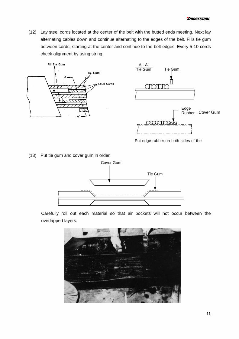
(12) Lay steel cords located at the center of the belt with the butted ends meeting. Next lay
alternating cables down and continue alternating to the edges of the belt. Fills tie gum
between cords, starting at the center and continue to the belt edges. Every 5-10 cords
check alignment by using string.
(13) Put tie gum and cover gum in order.
Carefully roll out each material so that air pockets will not occur between the
overlapped layers.
Tie GumA - A’
Tie Gum
EdgeRubber= Cover Gum
Put edge rubber on both sides of the
Cover Gum
Tie Gum
12
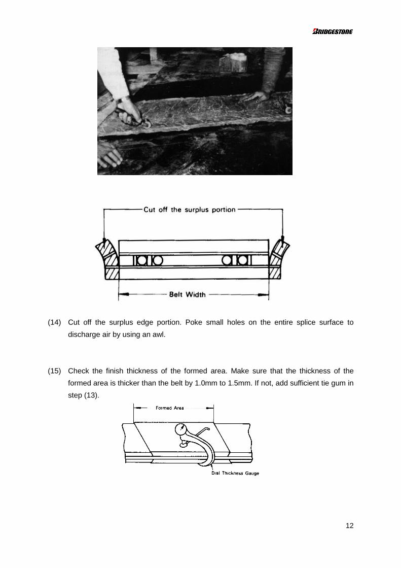
(14) Cut off the surplus edge portion. Poke small holes on the entire splice surface to
discharge air by using an awl.
(15) Check the finish thickness of the formed area. Make sure that the thickness of the
formed area is thicker than the belt by 1.0mm to 1.5mm. If not, add sufficient tie gum in
step (13).
13
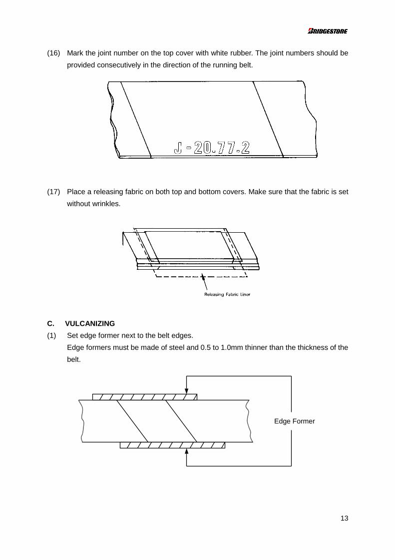
(16) Mark the joint number on the top cover with white rubber. The joint numbers should be
provided consecutively in the direction of the running belt.
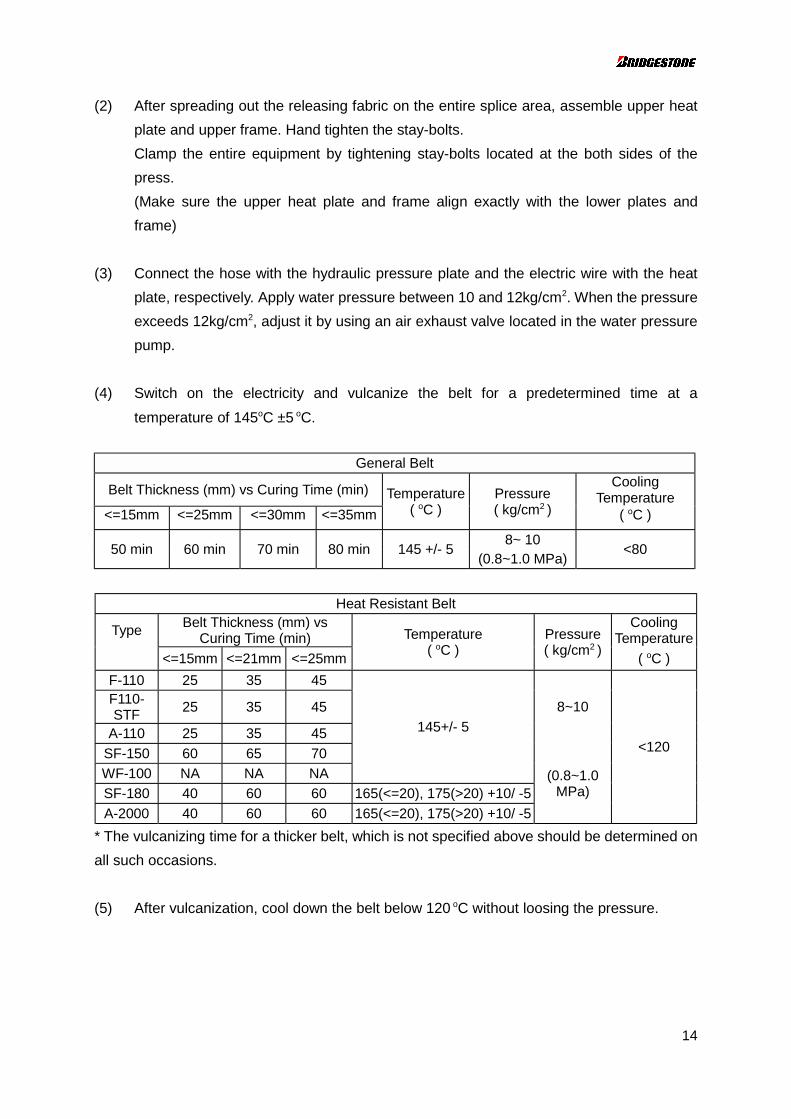
(17) Place a releasing fabric on both top and bottom covers. Make sure that the fabric is set
without wrinkles.
C. VULCANIZING
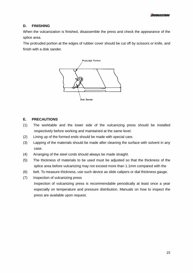
(1) Set edge former next to the belt edges.
Edge formers must be made of steel and 0.5 to 1.0mm thinner than the thickness of the
belt.
Edge Former
14
(2) After spreading out the releasing fabric on the entire splice area, assemble upper heat
plate and upper frame. Hand tighten the stay-bolts.
Clamp the entire equipment by tightening stay-bolts located at the both sides of the
press.
(Make sure the upper heat plate and frame align exactly with the lower plates and
frame)
(3) Connect the hose with the hydraulic pressure plate and the electric wire with the heat
plate, respectively. Apply water pressure between 10 and 12kg/cm2. When the pressure
exceeds 12kg/cm2, adjust it by using an air exhaust valve located in the water pressure
pump.
(4) Switch on the electricity and vulcanize the belt for a predetermined time at a
temperature of 145oC ±5 oC.
General Belt
Belt Thickness (mm) vs Curing Time (min)Cooling
Temperature<=15mm <=25mm <=30mm <=35mm
Temperature( oC )
Pressure( kg/cm2 ) ( oC )
8~ 1050 min 60 min 70 min 80 min 145 +/- 5
(0.8~1.0 MPa)<80
Heat Resistant Belt
TypeBelt Thickness (mm) vs
Curing Time (min)Cooling
Temperature
<=15mm <=21mm <=25mm
Temperature( oC )
Pressure( kg/cm2 )
( oC )
F-110 25 35 45F110-STF
25 35 45
A-110 25 35 45
8~10
SF-150 60 65 70
WF-100 NA NA NA
145+/- 5
SF-180 40 60 60 165(<=20), 175(>20) +10/ -5
A-2000 40 60 60 165(<=20), 175(>20) +10/ -5
(0.8~1.0MPa)
<120
* The vulcanizing time for a thicker belt, which is not specified above should be determined on
all such occasions.
(5) After vulcanization, cool down the belt below 120 oC without loosing the pressure.
15
D. FINISHING
When the vulcanization is finished, disassemble the press and check the appearance of the
splice area.
The protruded portion at the edges of rubber cover should be cut off by scissors or knife, and
finish with a disk sander.
E. PRECAUTIONS
(1) The worktable and the lower side of the vulcanizing press should be installed
respectively before working and maintained at the same level.
(2) Lining up of the formed ends should be made with special care.
(3) Lapping of the materials should be made after cleaning the surface with solvent in any
case.
(4) Arranging of the steel cords should always be made straight.
(5) The thickness of materials to be used must be adjusted so that the thickness of the
splice area before vulcanizing may not exceed more than 1.1mm compared with the
(6) belt. To measure thickness, use such device as slide calipers or dial thickness gauge.
(7) Inspection of vulcanizing press
Inspection of vulcanizing press is recommendable periodically at least once a year
especially on temperature and pressure distribution. Manuals on how to inspect the
press are available upon request.