steady-state injections in semiconductors· bound... · steady-state injections in semiconductors...
TRANSCRIPT

------------_-------- ----_ - ---
H. J. C. A. NUNNINK 539.2:537.311
R 464 Philips Res. Repts 17, 479-512, 1962
STEADY-STATE INJECTIONS IN SEMICONDUCTORS·
.by F: van der MAESEN, C. A. A. J. GREEBE and
SummaryIn this paper a survey is given of the theory of the behaviour of an in-jection for the case of a semi-infinite p-type semiconductor at one sideof which a steady-state deviation of electrons and holes is maintained.The recombination is thought to be due to a Shockley-Read mechanismarising from the presence of one set of recombination centres in theforbidden zone. The theory takes account of trapping in donors andacceptors, furthermore the limitation of the use of the "space-chargeneutrality approxirnation" is discussed. A case is considered where thenumber of injected carriers is large with respect to the number of re-combination centres, but small with respect to the number of donorsand acceptors. Numerical results on the numbers of excess holes andelectrons as a function of the distance into the semiconductor are. pre-'sented for examples that are representative of injections into germaniumand silicon, and this IS done for the entire range of very low. to verylarge injections, under conditions of space-charge neutrality, and forvarious values of an applied electric field. In the case representative ofsilicon, calculations were performed assuming the conditions for roomtemperature and liquid-air temperature; curves for the electric field andthe space charge are also given in a number of cases. The results, whichare presented in the form of tables and plots of dimensionless quantities,may be of importance in phenomena concerned with the transport ofexcess carriers, such as photoconductance and PEM-effect and thebehaviour of P-N junctions. Furthermore they may be of importancefor other semiconductors were conditions occur similar to those assumedin the given examples, especially with regard to trapping phenomena.
IRésuméUne revue de la théorie de l'injection dans un semiconducteur serni-infini,de type p, lorsqu'on maintient à l'un de ses cötés une déviation constanted'électrons et trous, est presentée. On pense que la recombinaison estcauséeparunméchanisme de type Shockley-Read, qui utilise la présenced'une série de centres de recombinaison à l'intérieur de la zóne interdite.Les effects de la capture dans les donneurs et les accepteurs sont con-sidérés, et on discute les limitations à l'usage de "l'approximation dezéro charge d'espace". Une situation dans laquelle Ie nombre de porteursinjectés est grand en comparaison de celui des centres de recombinaison,mais petit en considération du nombre des donateurs et des accepteursest décrite. On présente-des résultats numériques des calculs qui se rap-portent à l'injection dans Ie germanium et Ie silicium, et qui dormentle nombre des trous et des électróns en excès, en fonction de la distancedans Ie semiconducteur, pour toute sort d'intensité de l'injection, sousles conditions de zéro charge d'espace, et pour diverses valeurs du champélectrique appliqué. Dans Ie cas très particulier du silicium on a supposéque la température était celle de I'air ambiant et de l'air liquide; dans uncertain nombre de cas on trouve aussi des courbes en fonction du champélectrique et de la 'charge d'espace. Les résultats, présentés en forme detableaux et de grafiques de quantités sans dimensions, peuvent être utilesdims les phenomènes oû il s'agit du transport de porteurs en excès,tels que la photoconductivité, l'effect PEM, et des propriétés des

480 F. van der MAESEN. C. A. A. J. GREEBE and H. J. C. A. NUNNINK
jonctions p-Il. lIs peuvent même être utilisés pour semiconducteursdifférents, quand il y a de, situations analogues à celles discutées dansles exempJes, surtout pour ce qui se rapporte aux phénornènes de capture.
Zusammenfassung
In dieser Arbeit wird ein Überblick der Theorie des Verhaltens einerInjektion gegeben für den Fall eines halbunendlichenp-Typ-Halbleiters,an dessen einer Seite Unterschiede in der Elektronen- und Löcheranzahlstationär aufrechterhalten werden. Es wird angenommen, daB die Re-kombination nach einem Shockley-Read-Mechanismus erfolgt, der her-vorgerufen wird durch nur eine Art von Rekombinationszentren in derverbotene Zone. In der Theorie wird das Haften in Donatoren undAkzeptoren berücksichtigt, darliber hinaus wird die Gültigkeitsgrenzeder "Näherung der Ladungsneutralität" diskutiert. Es wird der Fall be-trachtet, daB die Zahl der injizierten Ladungsträger groB gegenüber derZahl der Rekombinationszentren, aber klein gegenüber der Zahl derDonatoren und Akzeptoren ist. Es werden numerische Ergebnisse liberdie Anzahl der überschüssigen Löcher und .Elektronen als Funktion desAbstandes im Halbleiter angegeben, die representativ für Injektionen inGermanium und Silizium sind, und zwar für den ganzen Bereich von sehrniedrigen bis zu sehr hohen Injektionen, unter den Bedingungen derLadungsneutralität und für verschiedene Werte des angelegten Feldes.In dem Fall, der für Silizium zutrifft, wurden Berechnungen für Raum-temperatur bzw. für flüssige Luft-Temperatur durchgeführt, In einerAnzahl von Fällen wurden auch Kurven für das elektrische Feld und dieRaumladung dargestellt. Die Ergebnisse, die in Form von Tabellen undgraphischen Darstellungen in dimensionslosen GröBen angegeben sind,können wichtig sein für Probleme, die überschüssige Ladungsträger be-treffen, wie z.B. Photoleitung, PEM-Effekt und das Verhalten von P-Il-Ûbergangen. Auch können sie für andere Halbleiter, in denen ähnlicheBedingungen vorliegen wie in den behandelten Beispielen, von Bedeutungsein, besonders in Hinblick auf die Hafterscheinungen.
1. Introduetion
Many papers have been published on the steady-state and transient behaviourofinjections in semiconductors 1-7). These problems usuallyinvolvedifferentialequations which only can be solved analytically in a number of simple cases,such as very small or very large injections. Nomura and Blakemore 8) haveperformed numerical calculations on injection phenomena. They consideredthe transient decay of a homogeneous distribution of excess carriers due toShockley-Read recombination 1). In the present paper numerical results forthe entire range from very large to very small injections are presented forseveral cases of a semi-infinite p-type semiconductor at one side of which asteady-state injection is maintained. As in the case treated by Nomura andBlakemore, the recombination is thought to be due to a Shockley- Readmechanism. Surface- and other bulk-recombination mechanisms are excluded.
The problem can be treated as a one-dimensional one, and our primarypurpose is to find the excess numbers of holes and electrons as a function ofthe distance. An additional aspect is the occurrence of concentration gradientsand the influence of the electric field. Furthermore, depending on the values ofthe gradients and the field, local space charges will be introduced. In the exam-
STEADY-STATE INJECTIONS IN SEMICONDUCTORS 481
ples considered however this spaoe-charge is so small thatthe numerical cal- "0culations are presented under the assumption of "space-charge neutrality".The characteristic parameters of the semiconductor have been given values
which can be considered representative of germanium and silicon. In the modelchosen foro-thecalculations, and which will be described ionsec. 2, trapping indonors and acceptors and the influence of an externally applied electric fieldare taken into account.The main equations which constitute the mathematical formulation of the
problem are given in sec. 3, together with a concise presentation of availableanalytical solutions such as for very small and very large injection levels. Alsoattention is paid to the validity of the so-called "space-charge neutrality ap-proximation". -
For the small-injection case, the ratio of the excess concentrations of electronsand holes án] áp = K seems to be a useful parameter in the mathematicalanalysis. One ofus has earlier described a method by which K can be determinedexperimentally 9).
Section 4 is concerned with the values of the various parameters and thepresentation of the numerical solutions.The "germanium case" consists in the treatment of an injection into ger-
manium at room temperature; trapping in donors and acceptors is neglectedin this case. In the "silicon cases" two temperatures are considered: roomtemperature and liquid-nitrogen temperature. Again, at room temperature thetrapping in donors and acceptors may be neglected, but at the lower tempera-ture a large amount of trapping occurs. In all cases the boundary conditionsin these cases are that Lln and áp vanish at infinity.
The appendix contains the detailed mathematical analysis of the variousaspects ofthe problem. Here a presentation is given in dimensionless quantities.These quantities were first used by Nomura and Blakemore 8); we.made exten-sions where necessary.The numerical results presented may give an insight into the behaviour of
injections near p-n-junctions, in photoconductivity problems, PEM-effect, etc.,especially in cases where the numbers of excess carriers are of the order of theequilibrium majority-carrier density. In this region of injection levels non-linearities in the differential equations are encountered, which make a numericalapproach appropriate.
TABLE I
NOTATIONS
concentration of donors, acceptors "andrecombinationcentres

ratio of excess numbers of holes and electrons; "'0 refers. to the space-charge neutrality approximation for lowinjectionsmobilities and diffusion constants of holes and elec-tronsratio of electron-to-hole mobilitydistanceelectric fieldapplied electric field.hole, electron and total current densityfraction of acceptors, donors and recombination cen-tres, occupied by electronschanges in fA, In, and jil due to injectioncapture rates for electrons and holes of donors andacceptors respectivelycapture rates for electrons and holes of recombinationcentresappropriate capture constantsconcentration of electrons and holes when Fermi levelis at appropriate levelintrinsic concentrationsthermal velocity of the electronscapture cross-sections for electrons and holesgeneral diffusion length for exponential behaviourdiffusion-recombination length with and without anapplied field for low jnjectionsdiffusion-recombination length for very high injectionsdiffusion-recombination length in extrinsic p-materialDebije-Hückellength in extrinsic p-type material with-out trappingcharacteristic length of space charge solution with andwithout an applied fieldFurther quantities have their usual meaning or aredenoted in the text.
482 F. van der MAESEN. C. A. A. J. GREEBE nnd H. J. C. A. NUNNINK
Nv, Ne effective density of states in valence and conductionbands
po, no, Ap, !Jn equilibrium and excess concentrations of holes andelectrons
p, 11 total concentrations of holes and electrons
f3uEEoJp, Jn,'JofA,fn,fR
!JIA, !JIn, !JjilSn, s;
Fn, Gp, c; c;ntn, PAl, nss, PRI
ni = Pt'l'nun, up
LLnR, LOnR
LOOnRLOn = (Dn/Cn)tLOnH = (soSrkT/q2po)t
L_se, LOse
STEADY-STATE INJECTIONS IN SEMICONDUCTORS 483
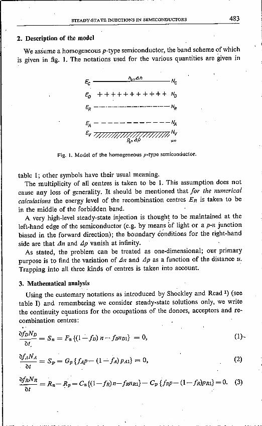
2. Description of the model
We assume a homogeneous p-type semiconductor, the band scheme ~f whichis given in fig. 1. The notations used for the various quantities are given in
n,Lln£c __:_:!IU..=.:.:_ Ne
£D ++ + + + + + + ++ + ND
ER - ------------._-------- NR
EA- -----------NA
£v ////////////// ////////# NVPo, LIP ""
Fig. 1. Model of the homogeneous p-type semiconductor.
table I; other symbols have their usual meaning,The multiplicity of all centres is taken to be 1. This assumption does not
cause any loss of generality. It should be mentioned that for the numericalcalculations the energy level of the recombination centres ER is taken to bein the middle of the forbidden band.A very high-level steady-state injection is thought to be maintained at the
left-hand edge of the semiconductor (e.g. by means of light or a p-n junctionbiased in the forward direction); the boundary conditions for the right-handside are that Lln and LIp vanish at infinity.As stated, the problem can be treated as one-dimensional; our primary
purpose is to find the variation of Llil and LIp as a function of the distance u.Trapping into all three kinds of centres is taken into account.
3. Mathematical analysisUsing the customary notations as introduced by Shockley and Read 1) (see
table I) and remembering we consider steady-state solutions only, we writethe continuity equations for the occupations of the donors, acceptors and re-combination centres:
bfnNn ._- = Sn = Fn {(1- fn) n- fnnDl} = 0, (1),b(
b/ANA~ = Sp = o; {/Ap- (1- fA) PAl} = 0, (2)

484 F. van der MAESEN, C. A. A. J. GREEBE and H. J. C. A. NUNNINK
These equations state that the recombination centres can exchange carrierswith both conduction and valence bands, whereas the donors and acceptorsaresupposed to have communication only with the conduction and the valenceband, respectively.Because Sn and Sp in (1) and (2) are zero, the continuity equations for the
electrons and holes are
'(ln I (JJn-=---Rn=O.(Jt q (JU .
(4)
op I (JJp- = - - -- Rp = 0,(Jt q (Ju
(5)
with, according to (3),
and
(7)
(8)
Furthermore,
J« + J» = Jo = q(!-'nno + !-,ppo}Eo. (9)
The gradient of the electric field is related to the space charge by Poisson'sequation:
When the "space-charge neutrality approximation" is applied, (10) is replacedby
(11)
This does not mean that ()E/(Ju also vanishes in this approximation. The useof (11) is only justified because in many cases the space charge necessary toobtain the required fields is so small that the quantity (11) may be taken tobe zero. We will discuss the limits of validity of this approximation later.The equations (3), (4), (5), (7), (8) and (10) or (11) can be regarded as the
main equations for the injection behaviour and several equations can be de-duced from them.An important expression for the electric field can be derived from (7), (8)
and (9):

STEADY-STATE INJECTIONS IN SEMICONDUCTORS 485
Jo - qDnonlou + qDpoplouE= .
q(p.nn + p.pp)(12)
3.1. Low injection levels*)We now give some results derived in the appendix for the low-injection case.
For very small deviations from equilibrium we may follow a process of linear-izing the equations given in the first part of this section. Poisson's equation (10)then takes the form:
dE q- = - {ALlp- BLln}du BOBr
(13)
which, in the space-charge neutrality approximation reduces to
ALlp- ss» ~ 0; (14)
A and B are defined by _
CpN RPRlPO NAPAA=I+-- +, (15)
(CnnRl + Cppo) (po +PRl)2 {po +PAl)2
CnN RP02 NonuiB= 1+----- + , (16)
(CnnRl + Cppo)(po + PRl)2 (no + nDl)2
where the various terms describe the distribution of excess electrons and holesand therefore the extra space charges in the appropriate bands and centres.The expression (16) for B can be rewritten in a form which is symmetric to (15)as far as electrons and holes are concerned:
CnNRnRlnO . Nontn.B = 1+ + (16a)
(CpPRl + Cnno) (no + nRl)2 (no + nDl)2
In the numerical calculations we shall assume nm. = PRl = ru. In the ap-pendix it is shown that linearization of the main equations leads to a fourth-order linear differential equation which describes the behaviour of Lln as wellas LIp. Hence the solutions can be written as
4Lln= ~ Pt exp (uiLt),
/-1
(17)
4LIp = ~ Qt exp (uiLt).
/ ~ 1(18)
In (17) and (18) the coefficients obey the relations:
") During the preparation of this article, an extensive treatment of the low-injectioncase was published by F. Stöckmann in Phys. Stat. Sol. 2,517-534,1962. Dr. Stöckmannobtained many of the results discussed here.
(êOêrkT)l/2LODH = -_'_ .q2pO (20)
486 F. van der MAESEN. C. A. A. J. GREEBE and H. J. C. A. NUNNINK
;t = Pt = A - {PO/(PO + (JpO)} (LODH/Lt)2 (1- qEoLtJkT) . (19)Qt, B- {{Jpo/(po+ (Jpo)} (LODH/Lt)2 (1 +qEoLt/kT)'
LODH is a Debije-Hückel length, defined by the equation
The four values of Li can be obtained from a fourth-order reduced equation(see the appendix). After these values have been found, the relations (17), (18)and (19) provide the complete solution of the problem for any boundaryconditions given, for example, by four fixed values of Lln and áp at the two sidesof the sample. In general, the Li cannot easily be found analytically. As acomplete discussion of the solution will be given elsewhere 10), we will confineourselves to some solutions which can be obtained quite directly.(a) In the case Eo = 0 it is at once to be seen that there are two pairs of
physically different solutions. One pair is connected with the diffusion and re-combination process and denoted by the subscript DR. The other pair is con-nected with the screening of space charge which can be introduced by theboundary conditions and will be denoted by SC. We obtain
LODR = ± LOn ( CnnRl + CpPo) (po + p Rl»)l/2,Cp(po + (Jno)po
(21)
11 Po 1/ êOêrkTLOse = ± LODH . = ± .Apo + Bne q2(Apo + Bno)
(22)
It can be seen that the well-known solution (21), which reduces to LOn forextrinsic p-material when the recombination centres are near the middle of theband gap, is independent of trapping because A and B do not occur in theseformulas .. Contrary to (21) A and B do occur in formulas for the space-charge solu-tions (22). •Equation (22) can be regarded as the more general formula for the Debije-
Hückellength when trapping occurs. For A and B = 1 it reduces to the well-known formula
(SOSr kT )1/2
LOse =LDH = ± .q2(PO + no)
For A = 1, po» no and no extreme values of B, eq. (22) reduces to (20); so(20) gives the Debije-Hückellength for extrinsic p-material with not too muchtrapping of electrons. Because A and B > 1, the Debije-Hückellength as givenby (23) is always reduced by trapping.
(23)

r-------------------- -----
(30)
STEADY-STATE INJECfIONS IN SEMICONDUCfORS 487
From (19), (21) and (22) we obtain important information on the ratios ofthe partial solutions for Lln and LIp in this case:
I
A - {po/(po + (Jpo)} (LODH/LoDR)2 ! .. KDR=B- {{Jpo/{po + (JPO)}(LODH/LODR)2' Eo = 0
"se = - no/po.
(24)
(25)
An interesting aspect of (24) and (25) is that for Eo = 0 the behaviour withrespect to trapping for the ,,'s is the reverse of the behaviour of the L's: «so isindependent of trapping and "DR depends on trapping. The second terms inthe numerator and denominator of (24) represent corrections in case spacecharge is present. From (25) it is seen that in the space-charge solutions recom-bination is absent.(b) When Eo =1= 0 the situation is considerably more complex. As is shown
in the appendix, separate space-charge and diffusion-recombination solutionscan still be found, provided the following conditions are fulfilled:
"0 = A/B» no/po, no/po « l/{J.
These conditions mean that the material should be extrinsic, whereas no extremevalues of B, that is no extreme minority-carrier trapping, should be allowed.These solutions are *): .
[qEo ~(qEO)2 4 tI2]-1
L±DR = 2 - kT ± I kT + LODR2~ , (27)
L± = 2 [qEO ~(qEO)2 _4 t/2]-1se kT ± I kT + LOse2~
(28)
For Eo> 0 the absolute values of L-DR and L+se are reduced, whereas thoseof L+DR and L-se are increased. The former two are denoted field-opposed,the latter field-aided solutions. For Eo < 0 this situation is reversed.From (27) we may obtain the following high-field solutions:
UDR = (qEoLoDR/kT) . LODR (field-aided) !IEol» kT/qLODR
L-DR = kT/qEo (field-opposed)
(29)
where according to (21) in this case LODR= LOn. In (29) and (30) the signs ofthe characteristic lengths depend now also on the sign of Ee. It should be
*) In (27) and (28) the solutions are presented as modifications of the values ofthe characteristiclengths for Eo = 0; therefore the notations se and DR are maintained. From a generaldiscussion of the solutions of the auxiliary equation, however, it appears that if due tothe electric field, the LDn and Lsc reach the same order of magnitude, such a notation israther inappropriate 10).

488 F. van der MAESEN, C. A. A. J. GREEBE and H. J. C. A; NUNNINK
noted furthermore that, in extrinsic material, eq. (29) represents the "Schub-weg", usually expressed as the product of the field, the mobility and the lifetime. Similar expressions can be obtained for the Se-solutions with a corre-'spending relation of the electric field. It should be mentioned here that in thecases for which our numerical solutions are carried out, only solutions with à.negative sign are appropriate.As can be seen from (19), the ratios of the partial solutions depend on the
field in a complicated way.
(c) General' solution for the space-charge-neutrality case for low injections.In this approximation we will always have:
KDR= KO= A/B. (31) ,
As is shown in the appendix, the two remaining diffusion-recombination solu-tions can be obtained from the following second-order equation:
1 Ko-nO/POqEo 1 1-+ -----=0··LDR2 KO+ no/PO kT LDR LODR2 ' (32)
(32) can be derived from the main equations in the limit for LDH ~ O. Forthe use of (32) the following conditions should be fulfilled:
LODR2» LOS02, (33)
E02 «(kT/qLOsO)2, (34)
E04 «g-4(kT/qLOsO)2(kT/qLODR)2, (35)where
1(0- no/po(36)g=
KO+ no/po
Condition (35) holds for the field-opposed case and gives a lower limit than(34) for extrinsic cases and no extreme trapping (g R::i 1).With (34) and (35) it is possible to define the following upper criticallimits
for the values of the electric field with respect to the use of the space-chargeneutrality condition:
Eoer"": kT/qLOso (37)or
(38)
With respect to the use of (32) it may be convenient to introduce an effectivefield of the form
EOeff = «s«. (39)
For the intrinsic case (no = po) with equal amounts of trapping for holes

STEADY-STATE INJECTIONS IN SEI,VIICONDUCTORS
and electrons or negligible trapping (KO = 1), we have g = 0 and therefore
which shows that the electric field has no influence on the diffusion length.For the extrinsic case (no« po) and no extreme trapping (KO» no/po),
g = 1, we obtain the solutions (27) again. Whether these solutions give riseto appreciable space charge or not is dependent on the conditions (34) and (35).
3.2. High injection levels
In the region of very high injection levels analytical solutions of the problemcan be obtained under the conditions of "space-charge neutrality" 5). Othersolutions, involving large amounts of space charge, are in principle possible,but can only be realized by extreme boundary conditions. A detailed analysisand a discussion of the validity of the results is given in the appendix. Here wesimply give the solution:
1=2
L1n = L1p = 1~l Ct exp (u/Lï), tL12 = LooDR± = ± LOn (2(Cn + Cp»)1/2. (
• Cp(1 + ,8) )
It should be noted that, at this high injection level, the diffusion length is in-dependent of the applied field Bo.
Due to the high modulation ·of the conductivity th€?influence of Eo vanishesin this region. The remaining field is the Dember fi_~ld,which is constant inthis region. For our boundary conditions: .
kT 1- ,8Eoo =-------.
qLOODR- 1 + ,8
In the high-injection-Ievel region, therefore, one has real space-charge neutrality,
3.3. Special cases
(a) A_very interesting case, which can arise in highly compensated material, canbe treated analytically in the intermediate region under the assumption of space-charge neutrality 11). When we have a small number of recombination centresnear the middle of the band-gap, small numbers of po and ne and not too deeptraps, we may have injections that are high as far as the number of recombina-tion centres is concerned, and which therefore have a linear recombination,but which are low as far as trapping is concerned. In the region where theseconditions are fulfilled, the ratio of the numbers of excess carriers L11l/L1p is
\ also a constant, depending only on the numbers of donors and acceptorsand their activation energies.
489
(40)
(41)
(42)

490 F. van der MAESEN, C. A. A. J. GREEBE and H. J. C. A. NUNNINK
The analysis of this case is given in the appendix. The results are:
1=2Lln = ~ Gi exp (u/Lt) , (43)
1= 1
1=2LIp . ~ Hi exp (u/Lt), (44)
1= 1
(2(C K + C )t2L = Lie ± = ± LO n ie p (45)1,2 DR n (1 + fJKie)Cp ,
withKie = A'/B',. (46)
where, NA
(47)A ~I+-,PAl
, ND(48)B ~I+-.
nui
The notation "ic" stands for "intermediate case".This real diffusion-recombination solution has a characteristic length which
is dependent on trapping, but independent of the electric field.(b) In many cases, such as in our "germanium case", we may neglect the
trapping in the donors and acceptors. The general eq. (11) for ,"space-chargeneutrality" then reduces to
(49)
In the special case that the position of the recómbination centres and thedope are connected in such a way that
(50)we have
KO = A/B = 1. (51)
As can be seen from the corresponding formula (7-A) in the appendix,LlfR depends in such a way on Lln-Llp that a further consequence is
Lln = LIp, (52)and therefore
(53)
over the whole range of injection levels. This means that there is no change ofoccupation of the recombination centres due to the injection. The rate of re-combination, which in this particular case can be derived from the formula (8-A)in the appendix, is

STEADY-STATE INJECTIONS IN SEMICONDUCTORS
CnCpRn = Rp = --- LJp •
Cp+ C«
Formula (54) states that the recombination is linear over the whole range ofinjection. It is clear that in this case one may speak of one life time T which isindependent of the injection-level density. Nonlinear behaviour in the inter-mediate range is now to be found in the diffusion and field terms only.It may be mentioned here that if one plots: LJn versus LJp according to (49),
one finds a hyperbola. If the condition (50) holds, this hyperbola degeneratesinto a straight line.
As a conclusion we may point out that except for the 'dependence of LOnon NR the results for this case are independent of NR. If NR is very small onealways arrives at the condition (52) from (49) but (53) and (54) only hold whenthe condition (50) is satisfied.(c) A solution valid for the whole range of injection densities can be found for
the intrinsic case no = po = Pt with negligible trapping and the recombinationlevels in the middle ofthe band. As is shown in the appendix, the solutions areexponentials over the whole range; the. characteristic length is given by (41).Indeed we find that (41) results if we put no = po = nux = PRl = Pt inexpression (21).
3.4. Intermediate injection levels
Intermediate injection levels cannot in general be treated analytically. If onestarts with a situation where the space-charge neutrality approximation maybe applied in the low-level region, one may expect this to hold over the wholerange to the very high injections, where it is also verified. We will investigatethis situation in the next section, where the numerical results are given.We should mention here that the amount of existing space charge over the
whole range of injection can be found from an evaluation of the field gradientaccording to (10) when the solutions are known. See eq. (72-A) ofthe appendix.
4. Numerical results
As has been mentioned in the introduction, numerical calculations were per-formed for models which can be regarded as representative of injections intosemi-infinite samples of germanium and silicon.The germanium model has only been considered at room temperature;
furthermore in this case trapping in donors and acceptors has been neglected.The silicon model, however, has been considered at room temperature and at77 "K, In the latter case trapping becomes important.The sets of parameter values for which computations have been carried out
are presented in the form of tables together with characteristic quantities, such
491
(54)

492 F. van der MAESEN. C. A. A. J. GREEBE and H. J. C. A. NUNNINK
as the diffusion length for low and high injections, which can be computedfrom them.The results are mainly presented in the form of graphical curves of several
dimensionless entities such as x = ,1n/po, y = ,1p/po, e =q ELon/kT versus thereduced distance z = u/Lon, LOn = (Dn/Cn)t. The values of e were calculatedwith the reduced form of (12), that is formula (16-A) in the appendix. It shouldbe emphasised that the boundary conditions E--£o, ,1n, áp ---+ 0, for u---+ 00
have been imposed and that all solutions have been calculated under the as-sumption of "space-charge neutrality". Furthermore, the recombinationcentresNR are in the middle of the band-gap.With respect to the condition for the use of eq. (32) for low injections, the
critical values of the electric field are given by (37) or (38). Which formula isused is denoted in the appropriate column of the tables. The numbers of thecurves correspond to the numbers of the cases in the tables.Because of the fact that for a number of cases the curves given in the dimen-
sionless quantities are the same or practically the same, not all curves are pre-sented.
4.1. The germanium models
The cases which have been considered for the germanium model at roomtemperature are listed in table Il. Curves for ,1n/po = x, ,1p/po = y and e aregiven in figs 2 and 3.Basic parameters are given by the following values:
ru = 7..5. 1013 cm-3ILn= 4000 cm2/Y secDn= 100 cm2/secSr = 16
,f3 = ILn/lLp = 2Cp/Cn = y = 10.
For tbe evaluation of the standard length LOn we need en. Taking the capturecross-section for the electrons Un = 10-17 cm-, and for the thermal velocity107 cm/sec, we have
C« = NRUnVn = 10-10 NR sec-I,LOn= (Dn/Cn)! = (1012/NR)! cm.
For the Debije-Hückellength LODHwe find:
(sosr kT)1/2
LODH = -- = 1·5 (l05/PO)! cm.q2po .
Apart from a slight shift in the values of ,1n and /Jp of about"8 % (KO = 0·92)in the low-injection range, the curves of ,1n/po, ,1p/po and e versus the reduced

('()0\
""" TABLE 1ICharacteristics of the germanium model
~
~§::s~~~
iIîl
~
i
no. po nt/po no/po Nelp« A B A/B g qEoLOn L-DR LOsc2 qEoerLOn LOn curve remarks-W- L,on LODR2 =tr: cm
reduced ~ a=b ab NR I/a a02/w02
valuesKO eo eOer
1 2.5.1015 10-2 10-4 1 1·0098 1·098 0·92 1 10 0'099 2'3.10-7 45(38) 2'0.10-2 Extrinsic
2 u u u u u u u u 1 0·620 u u u
3 u u u u " " " "0 1·005 " " "
Effect offields as in no.
4 " " " " " " " "-1 1-631 " " "
6 -10
5 " " u " u u " u -10 10·20 u u "6 2'5.1014 ~10-1 1O~2 1 1·082 1·082 1 0'980 10 0·101 2.1.10-7 47(38) 6'3.10-2 fig. "2 Extrinsic
7 u u u u u u u u 1 0'644 " " u u Lln = LIp
8 u u u " u u u u 0 1·044 u u u "9 " u u u u " u u -1 1·707 u u u u Effect of field
10 u u u u u u " u -10 10·71 u u u u
11 2'5.1013 I 1 10-1 1·023 1·0023 1'020 0·010 10 0·820 1.5.10-8 9400(37) 6'3.10-1 Intrinsic
12 u u " u u u u u 1 0·853 u u uNegligible trapping
13 " " u u u u " u 0 0·856 " " "Negligible Influence of
14 " u " u u u u u -I 0·860 " " "field, practically exponent-
15 " " " u u " u u -10 0·894 u " u ial
16 2'5.1013 I 1 I 1·228 1·023 1·20 0·091 10 0·586 1.4.10-7 620(38) 2.0.10-1 fig.3
17 u ., u u " u u u 1 0·824 " " " "Intrinsic
18 " " " " " " " "0 0·856 " " " u Due to small amount of
19 u " u " " " " "-1 0'890 " " " "
trapping, remarkable in-
20 " " " " " " " "-10 1,252 u " " "
tluence of field
For all cases in this table: f3 = 2 Loo DR/Loll = 0·856y= 10
qEr;y:JLon/kT= er;y:J= 0·389

494 F. van der MAESEN. C. A. A. J. GREEBE and H. J. C. A. NUNNINK
distance z ~ u/Lon for the cases 1-5 are practically identical with those for thenumbers 6-10, and the curves 1-5 are therefore not given. One may thus usefor the cases 1-5 the curves 6-10 in fig. 2, remembering that the minority-carrierdensity lies at the level I0-4 on the same plot. Sincewith the group of cases 6-10
P, -2.5·1O'êm-3-\--\--1-·----:-~----------n:-2.5.10I2cm-i1"----
Nn=1.~--~~---- ~1
~-1.044~--+-4-~~~--~~---~~-----__L~~zaruo--__e,..0.389\----\'!---\,---_-lI- --...::::""'= L~..O.063cm _
e.=fO2r-~~1----+-_4r_-~~------ _1O-i1r---r--~,___-~--~--------- _
L~/L".= 0.101
Fig. 2. Values of ,1n/po = x, Ap/po = y and the reduced electric field e versus distanceu/Lon = z for the cases 6-10, Table IT, germanium model. In these cases x = y. The signson the e-curves denote the sign of e.
the condition (50) of sec. 3.3.b is fulfilled, we have here exactly KO = 1 andLln = LIp over the whole range of injection levels.Although the value of NR has no influence on the calculation of the curves
given in fig. 2, wemust remember that NR determines the value of the standardlength LOn. Furthermore it determines the absolute value of the electric fieldand the estimations ofthe limitations, i.e, (LOsa/LoDR)2 and eOer = qEocrL«'n/kT.As can be seen from the curves 6-10 the non-exponential behaviour liesmainly
in the region between the majority- and minority-carrier densities.For the cases 1-5 this has the consequence that the injection level may come
as.far as 100 times the minority-carrier density no before entering a region ofnon-linearity.

STEADY-$TATE INJECfIONS IN SEMICONDUCfORS 495
It is clearly seen from the slope at high injection-level.densities that the limitdenoted by Loo .QR/Lon = 0·856 is reached at a value of ,tjn/po = x = JO.Especially in the cases 7, 8 and 9 the limiting value for the electric field
11 I---\---\-""*-X,y,et 5
2
2~ ~~~~~~~~~ ~
W~'~ ~ __-+~-4r-__~ ~5;L-__ ~~~w_~~~A-_L~ __ L-~
10 -z 'u,'- __ -'- __-Fig. 3. Values of -1nfpo = x, L1pfpo= y and the reduced electric field e versus distanceufLon = z for the cases 16-20, table TI, germanium model. The signs on the e-curves denotethe sign of e.
eet:) = 0·389 is reached. This value is calculated from the appropriate formula(42) or (56-A). In the field-aided cases where eo is negative, the value of epasses zero and for this reason the sign of e is indicated on all e-curves.
With respect to the intrinsic cases 11-15we may remark that due to the veryslight trapping in the recombination centres we will have practica1ly an ex-ponèntial behaviour, as indicated in sec. 3.3.c. The curves for these cases 'aretherefore not given either. The calculations show, however, the slight depend-ence on the low injection penetration due to the very small amount of-trappingof 2% (KO = 1·02).
As can be seen from the figures and curves ofthe intrinsic cases 16-20 (fig. 3),

496 F. van der MAESEN. C. A. A. J. GREEBE and H. J. C. A. NUNNINK
the electric field -has quite a remarkable influence, due to the trapping whichmay still be regarded as not too large.The limiting field strength for the use of the space-charge neutrality eq. (32)
is also greatly reduced by the trapping, compared with the intrinsic cases 11-15.As a conclusion we may state that, as appears from the. figures in table II,
the conditions for space-charge neutrality were fulfilled for every case.
4.2. The silicon models
With respect to the various models of samples of Si we have made a division, into two parts: for one set of samples (table Ill) we have Cp/Cn = y = 10-1and for the second set Cp/Cn = y = 10 (table IV). Physically this means thatin the first set we think of donor-type recombination centres which change theircharge from positive to neutral by capturing an electron; for the cross-sectionwe usually have Up < o« in that case. For the second set the recombinationcentre is acceptor-like; the charge ofthe centre changes from negative to neutralby capturing a hole and it can be expected that Up > o«.We deduced a reason-able set of values for Un and Up from the articles of Bemski and Davies 12.19).For the construction of our p-type models at room temperature in equilibrium
(marked A) we chose cases where the Fermi level was somewhere in between therecombination centres and the acceptor levels in such a way that the levelswere empty or fully occupied.Therefore the quantities NR, NA, ND and Po of the samples at room tem-
perature (marked A) have to obey the following relations:
y = 10-1 (table Ill), ND+ + NR+ +Po = N[, (55)
y = 10 (table I":'), ND+ + po = N[. (56)
For po we have taken values of 1014 and 1016 cm-3 at room temperature anda number of recombination centres N R = 0·1Po. In the cases where (55) applies,a large number of NR, (NR >po), should require quite a degree of compen-sation. Investigation showed that smaller amounts of NR, (NR «po), give onlyminor differences in the results for the room-temperature cases when plottedin the dimensionless quantities. The characteristics of the chosen examples atthe liquid-nitrogen temperature (marked B) are obtained by applying the.normal statistics. Here we have to assume values for the donor and acceptorionization energies ED - Ea and EA - Ev and the density of states in thevalence and conduction bands Nv and Na.
For reasons of simplicity it is assumed that the ratio of the mobilitiesf3 = /Ln/ t-» and y = Cp/Cn are independent of temperature and furthermoreNv = Na. Acceptable values for the various quantities are taken from theliterature. The following set of basic data is used:
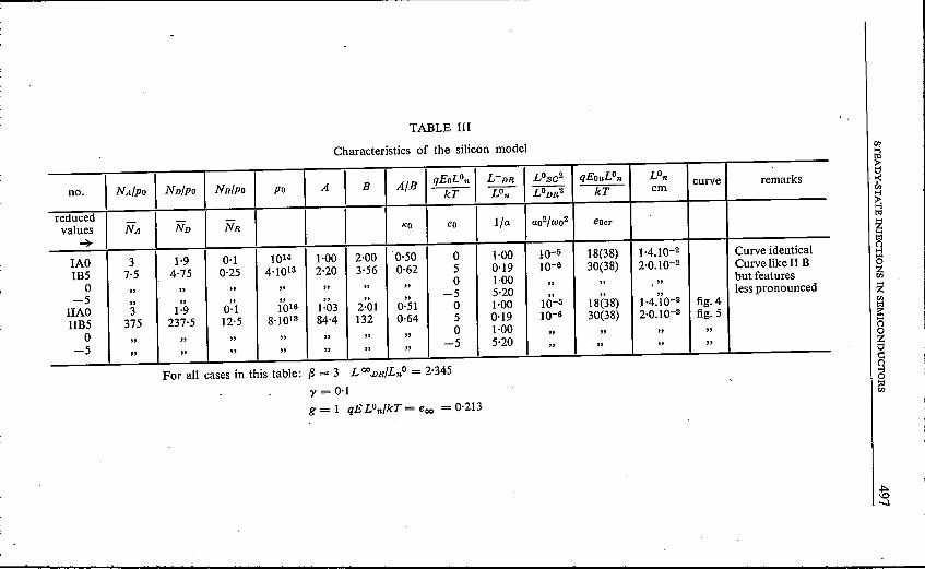
TABLE III
Characteristics of the silicon model
no. I NA/PO Nnl p« NR/po po A I B A/B I qEoLOn I L-DR I LOsc2 qEouLOn LOn curve remarkskT LOn LODR2 kT cm
reduced I I I Ivalues NA ND NR KO eo I/a ao2/wo2 eoer
~IAO 3 1·9 0·1 1014 1·00 2·00 0·50 0 1·00 10-5 18(38) 1.4.10-2 Curve identical
IB5 7·5 4·75 0·25 4.1013 2·20 3·56 0·62 5 0·19 IQ-6 30(38) 2.0.10-2 Curve like II B
0 " " " " " " "0 1·00 " " "
but features
-5 " " " " " " "-5 5·20 " " "
less pronounced
IIAO 3 1·9 0·1 1016 1·03 2·01 0·51 0 1·00 10-5 18(38) 1.4.10-3 fig.4
HB5 375 237·5 12·5 8.1013 84·4 132 0·64 5 0·19 10-6 30(38) 2.0.10-3 fig.5
0 " " " " " " "0 1·00 " " " "
-5 " " " " " " "-5 5·20 " " " "
For all cases in this table: f3 = 3 L ooDR/Lno = 2·345y = 0·1g = 1 qE LOn/kT = eoo = 0·213
!~t%lg~~Zent%ls::n~g~~
~-..l

"
TABLE IV
Characteristics of the silicon models
no. NA/PO ND/po Jl(R/PO Po I A I B A/B I qEOLOn I LDR- LOsa2 qEOerLOnLOll/cm curve remarkskT LOn LODR2 =sr:
reduced
I I I ! ao2/wo2!
values NA ND NR KO eo I/a eOer~IIIAO 3 2 0·1 1014 1·00 1-01 0·99 0 1·00 10-6 30(38) 4.5.102 Curve same as IVAIIIB5 7·5 5·0 0·25 4.1013 2-20 1-09 2·02 5 0·19 3.10-7 45(38) 6.3.10-2 Curves alike0 " " " " " " " 0 1·00
" " " IVB but features-5" " " " " " " . -5 5·20
" " " less pronouncedIVAO 3 2 0·1 1016 1·03 1·03 1·00 0 1·00 10-6 30(38) 4.5.10-3 fig.6IVB5 375 250 12·5 8.1013 84·4 8·50 9·92 5 0·19 2.10-7 50(38) . 6.5.10-3 fig.70" " " " " " " 0 1·00
" " " fig.7-5" " " " " " " -5 5·20
" " " fig.7
For all cases in this table: f3 = 3 LOO DR/Lo" = 0·741y = 10
g = 1 qE LOn/kT = eoo = 0·675
~00
:n§ft:::~m:zÇl
?>?>!:-<Cl6l!:lmgc,
;z:!:-<Çl
?>z
~?::

STEADY-STATB INJECTIONS IN SEMICONDUCTORS 499
Room temperature
ni = 1010p'n = 1600Dn':'_ 40Nv=No = 1019Vn = 2.107
liquid-nitrogen temperature
3.15-13 cm-36400 cm2/Vsec 14,15)
40 cm2/sec -1.3.1018 cm-3107 cm/sec.
5~--------~-------------------------'\' L"'m/L~= 2.3452~ ~ _4
m2~ ~~ -4
~X'te 51-------\\-----=-_-_..:::_-_-~--121--------''\--\-- -·-·-e--
w~--~~--~\~----~~ .. 10 cm-3
5~----~=3 ~\'__-------------4&..1.9
2~-- __~ ..al------------~----------~~;'=0.1 ~ \.majority !-,-_-~=1 ,.'f.DR"'2.345 4 -4
carrier 1- Lo. Lo \density 5~----em,.0.213 -3 "
L~=1.4·10 cm "l,2 ~0.213 ._. .. ----.-.,\\
"1Ö'~------------------------~~-------;''.HAO
51---------------------------~,~\,----~
2~--------------------------~~\.\'-\-----4~2~----------------------------~~~-4W'·=O5~----------------------------~~~\\----,2~------------------------------~---4\\\
10~~--~--------------------------~.--4
"5C===~==~===c==~==~====rj-\I=j5 10 ,6l'o _z
Fig. 4. Values of ánlp« = x, Ap/po = y and the reduced electric field e versus distanceu/Lon = z for the case HAO, table Ill, silicon model, room temperature. e is positive.
IParameters assumed to be independent of temperature are: er = 12, (3 = 3,
Table Ill: Cp/Cn = Y = 10-1, an = 10-15 crrr=, 12,13)
Table IV: Cp/Cn = Y = 10' , an = 10-16 cm-2, 12,13)
Eo - ED = 0·04 eV f.e. phosphor 16),
EA- Ev = 0·06 eV f.e. aluminium 16).

500 F. van der MAESBN, C. A. A. J. GREBBE and H. J. C. A. NUNNINK
X,Y.
majOriJearnersdenslly
10 \5
y'b-+5 \,e
,. \ \ _""",.- .._'-------- eo"'-52t-e+'
\ \ <>:1 \
--- I \ e~~ \ r-. & ",8·10'3cm-3I \-. \ --X5 \ '\ .,\ \\ ,. <. --V 1ft,=375
~~213\ \ . .....··t t<, -'-·-e No ",237.5 ,\ ...... _..mNR=12.5
2
\\\ \ . ...., .~U i ! ....,,. =0.1-,
1Ö' \ ' ",\m+ .\\ ,.
<, '1lB-5t'a/t'" =1 11
·1 L;/L~ =2.3455
11lB5 _1~llBOÜ, .............._..... -~
e",=0.2f3
" L~=2.0 .10-3cm: _o, _, ... ' .............~ ....... ....2
• I 'JTI \V ...........................~",10-2
i m+j ... \/. \: "f!i!
\ ~, .... ~: : \ \ '.... ......5 . : . \ <. -,
I'
\ \\, -.~:! -, ....2 ~=5 \ \eo"'O .......... ......~~oz-5
~/L~ t;0~~, • 'J?J-..:;_10-3 =0.19 z; ""'1.001 L;,;L~=5.20 ",
11'Ö.&l
Fig. 5. Values for tJn/po = x, tJp/po = y, the reduced electric field e, and the space charge III
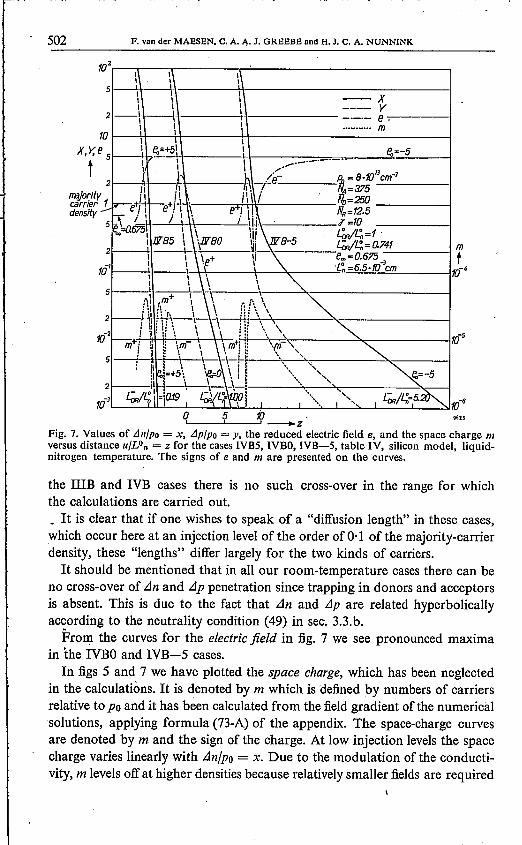
versus distance u/Lon = z for the cases IIB5, IIBO,lIB-5, table Ill, silicon model, liquidnitrogen temperature. The signs of e and m are presented on the curves.
As in the case of germanium we find for the LOn and LOnH:Room temperature
Table UI: LOn = (2.l09jNR)!Table IV: LOn = (2.1010jNR)t
LnH = (2.l05jpo)!
liquid-nitrogen temperature(4.109jNR)! cm, .(4.1010jNR)t cm,(4.104jJ'0)t cm.
In the numbering of the cases, I, U etc. denote silicon with various dopings NA,No, NR. A stands for room temperature, B for liquid-nitrogen temperature,whereas the numbers 0,5 etc. indicate the value of the electric field e in reducedunits. In all cases n1.jJ'o= a = b is neglected in the calculations and conse-quently g = 1. Furthermore if no field is applied LODR = LOn, i.e. the diffusion-recombination length has the 'value appropriate to extrinsic material.It is clear that as far as the low-level injections are concerned, and apart
from the value of the ratio KO, the behaviour with respect to the electric fieldis the same for the various cases. Furthermore the behaviour for the fields ± 1and ± 10 may be seen from the curves for the extrinsic germanium cases,specified in table U with the numbers 6 to 10.As in the case of germanium, various curves are not shown. For instance', it
can at once be expected that the curves for the cases IAO and UAOare practicallycoincident; the same holds for UIAO and IVAO. In some cases curves thatshow essentially the same features as other ones are omitted. .
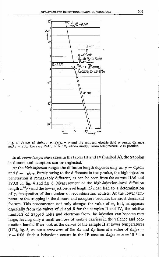
STEADY-STATE INJECI'IONS IN SEMICONDUCI'ORS 501
:~ ~f_A_O__ 1
-\\Sl--------\··\_ ---I\\21--------\'\.1-,,--1
m~·I--------~\-~I \ \ II
O'--- _ __:5L._ _ _.:.;10--+z "14
Fig, 6. Values of Lln/po = x, Llp/po = y and the reduced electric field e versus distanceu/Lon = z for the case IVAO, table IV, silicon model, room tempreature. e is positive.
In all room-temperature cases in the tables III and IV (marked A), the trappingin donors and acceptors can be neglected.
At the high-injection ranges the diffusion length depends only on y = Cp/Cnand f3 = fLn/ fLp. Purely owing to the difference in the y-value, the high injectionpenetration is remarkably different, as can be seen from the curves IIAO andIVAO in fig. 4 and fig. 6. Measurement of the high-injection-level diffusionlength L 00 DR and the low-injection-level Iength LOn can lead to a determinationof y, irrespective of the number of recombination centres. At the lower tem-perature the trapping in the donors and acceptors becomes the most dominantfeature. This phenomenon not only changes the value of KO, but, as appearsespecially from the values of A and B for the samples n and IV, the relativenumbers of trapped holes and electrons from the injection can become verylarge, leaving only a small number of mobile carriers in the valence and con-duction bands: If we look at the curves of the sample 11 at lower temperatures(lIB), fig. 5, we see a cross-over of the Lln and LIp lines at a value of Lln/po =x = 0·06. Such a behaviour occurs in the IB case as Lln/po = x = 10-1. In
502 F. van der MAESEN. C. A. />,. J. GREEBE and H. J. C. A. NUNNINK--------------------~---------------------------105W-\\ \\
I 1'---------+\'Ir-------------::::--X---------4I I \ y2__ l-\ 1-1------------_._._e r-------1\ 1 \ m
10 1 I I
X, Y,e I ~+51 LI-- ===_...::!e..=-5t 5 1 I 1 •..-'_'
I \. I..... IJr r h /e.- ~ - 8·10 cm·J2~1' It ~. =r: - N
A=375 "':::'::~---I
major:Jty '1 i' i\ i\i flo=250eertter }...lr-e+!-t I--e+; I , il fl -----_1densHy for) \ j I ie! q i\ R=12.5
5 p '-n675-t --\- • I ti· d' =10 ---- __ 1-",""" \' \ii\~ L"m/L~=1.\ NB5 \ \NBO I:j NB-5 ~L~=o.7412--I --I W .:..:....---- mt
I I \\ + V \ em=0.6751rj' I I, ie L~=6.5·10·Jcm 10-4
\ \\\ \ -,5 -----I • \ '\.
1\\ ,m+ ~I \ dl \ -,21-D\ ih_\ \_ji!i_ \~\_\~ "'~:__-------------I
i~M \ \. lli \. \ ~1O·2f--.: ~.:. \ H' :j...' ---:',.,.. -2-'..---------""'~:__--------_11O-5
mi' i ~ ~ \m- \~~m+J i! \{TI-:-"" <,5~ : \ \ ~~.~~-----:\~-,~--------~""'~-------~
, :1 l \ \ "~ '.', ~, !1~1=+5\ ~ \! S ...... ", e.=-5
2 :!' \ i' ~
..-
0510 ~~--~--~ ---.zFig. 7. Values of t11l/Po = x, t1p/po = y, the reduced electric field e, and the space charge /11
versus distance u/Lon = z for the cases IVBS, IVBO, lVB-S, table IV, silicon model, liquid-nitrogen temperature. The signs of e and III are presented on the curves.
the lUB and IVB cases there is no such cross-over in the range for whichthe calculations are carried out._It is clear that if one wishes to speak of a "diffusion length" in these cases,which occur here at an injection level of the order of 0·1 of the majority-carrierdensity, these "lengths" differ largely for the two kinds of carriers.It should be mentioned that in all our room-temperature cases there can be
no cross-over of L1n and L1p penetration since trapping in donors and acceptorsis absent. This is due to the fact that L1n and L1p are related hyperbolicallyaccording to the neutrality condition (49) in sec. 3.3.b.From the curves for the electric field in fig. 7 we see pronounced maxima
in the IVBO and IVB- 5 cases.In figs 5 and 7 we have plotted the space charge, which has been neglected
in the calculations, It is denoted by m which is defined by numbers of carriersrelative to Po and it has been calculated from the field gradient of the numericalsolutions, applying formula (73-A) of the appendix. The space-charge curvesare denoted by m and the sign of the charge. At low injection levels the spacecharge varies linearly with L1n/po = x. Due to the modulation of the conducti-vity, m levels off at higher densities because relatively smaller fields are required

STEADY-STATE INJECTIONS IN SEMICONDUCTORS 503
(J-)~
2 ".. CNAl_.- - ~
_.// 7 / x-/' 7
~7{_ /-._ 'NRJ--.- v- ./i-i- - -I-- -V l- V /
I-- -i- - r-_. - _.'_ t7 -- I-- ti'~ lL V 1-- I--/ i- -i- V 17.~ "..
~V'y.~ ,-- - l-r
Z _.,- - t7;~~ -- - -- I-2 r. R '-- T i- -I-- -- - -- - i- f-
- _j!I~ -~V--- -i- f- ----_.- -1- - r--;/- ?~
Case lIB_.- --_.- -_. - I-
~
L_ -
- - - -
Fig. 8. Occupation of donors (ND-), acceptors (NA+) and recombination centres (NR-) withexcess holes and electrons, expressed in numbers relative to po, together with x(x-) andy(y+), as a function of x, for the case lIB.
___, - ._ --1 .-1- (k:J:z- - ->.- ~? rNö)_i- - ,- I--
~,
e~~
-~-....-:: >tr-I// =~/I-~br-/- u 7-b (N"R)
./ 7 -r:::_~ f-7!L
A I'~ /
~ / ._-l-SA I' ./
~ /'N,+ ~ ~ /5- ':*CNRV /' Case lYB
3 '1!l;J ~ /5
.~ 1/Vx- I/v
4~ IV I.- - - 2
Fig. 9. Occupation of donors (ND-)~ acceptors (N[) and recombination centres (NR-) withexcess holes and electrons, expressed in numbers relative to po, together with x(x-) and y(y+),as a function of x, for the case IVB.

504 F. van der MAESEN. C. A. A. J. GREEBE and H. J. C. A. NUNNINK
It is clear that in the cases investigated the space charge is very small withrespect to the. numbers of injected carriers. This again justifies the use of thespace-charge neutrality equation (10) in the numerical calculations.The critical field in the tables is indeed much higher than the applied fields.In figs 8 and 9 we have plotted the various excess occupations of centres with
holes and electrons together with the free holes and electron densities as afunction of the free-electron density. This is only done for the IIB and IVBcases. All quantities are given relative to Po and can be directly deduced fromthe various terms in (9-A). The various curves for the donors, acceptors andrecombination centres are denoted by (ND), (NA) and (NR), x and y and bythe sign of the excess charge. In these figures, which also hold for homogeneousinjections, we see a striking difference between the IIB and IVB cases. In fig. 8for the IIB case, Cp/Cn = 0,1, non-linear behaviour of the various occupationsof NR, NA and ND starts already for LJn/po = x = 10-2, while in case IVBnon-linearity sets in at x = 0·3.The occupation of the recombination centres with electrons starts to saturate
at these values of the injection density.In case IIB (fig. 8) we see that due to the fact that the acceptors are not yet
saturated with trapped holes, the number of free holes lags behind when theinjection is increased. Because we have started with a situation where LJp/po =r > LJn/po = x (KO < 1), LJp becomes equal to LJn as K = 0·06 and the cross-over occurs. At higher densities LJp becomes much smaller than LJn. In factwe have here a situation as described in sec. 3.3.a. A simple calculation showsthat the ratio LJn/LJp changes from the low injection value KO = 0·64to Kic = 12.The value Kic = 12 is approached for K ~ 10. In this situation the semi-con-ductor is p-type in the low injection ranges, but becomes at higher injectionlevels (x ~ 10 -+ 100) a definite n-type conductor.Up to a level of K = 100 such a situation does not occur in the IVB cases,
as is shown in fig. 9.
S. Concluding remarks
It may be remarked that, although the examples are representative of thebehaviour of injections into p-type germanium and silicon, many features,especially those in the non-linear ranges, can be expected to occur at normaltemperatures in higher-ohmic samples of semiconductor compounds withdeep-lying donor and acceptor levels.
Acknowledgement
The authors wishto express their sincere gratitude to Ir F. H. Stieltjes andDr H. J. Vink for valuable and stimulating suggestions and discussions. Theyare also much indebted to Mrs A. B. de Jong-Crayé and Mr J. Vrakking fortheir help in plotting the numerical results.
Eindhoven, October 1962

STEADY-STATE INJECfIONS IN SEMICONDUCfORS 505
AppendixTable IA gives the definition ofthe dimensionless quantities used throughout
this appendix. These quantities were first used by Nomura and Blakemore 8);extensions have been made where necessary. All concentrations are written interms of the equilibrium carrier density po. The unit of length is LOn.All voltageshave been given in terms of kT/q.
TABLE IADEFINITIONS OF REDUCED QUANTITIES
x . = ./Jn/poy ./Jp/poNA = NA/POND = Nolp«NR = NR/POe = qELon/kTeo = qEOLon/kT
reduced excess electron densityreduced excess hole densityreduced density of acceptorsreduced density of donorsreduced density of recombination centresreduced electric fieldreduced applied field
7J = e-eoz = u/Lon reduced distance-a = nmlp», b = pmlps, e = nmlp», d = PAl/POjn = LOnJn/kT(.LpPo reduced electron current densityl» = LOnJp/kT(.Lppo reduced hole current densityjo = jn + i» reduced total current densityf3 = (.Ln/t-» ratio of electron-to-hole mobilityy = Cp/Cn ratio of capture constantso: = LOn/L reduced penetration coefficientID = LODH/Lon reduced Debije-Hückellength
Further quantities are indicated in the text.
(a) The main equationsThe main eqs (1) and (2) become
(1- fD)(ab + x) - foe = 0,
fA (1+ y)- (1- fA)d = O.
From (I-A) and (2-A) the deviations in fo and fA can be calculated:
.tJfD= ex (ab + e + x)-l(ab + e)-I,
.tJ/A= -dy (1+ d + y)-l(1 + d)-I.
For the recombination rates Rn and Rp we introduce the quantities
rn = (1 - /R)(ab t x) - fR a,
rp = y {/R (1 + y) - (1- fR) b}.
(I-A)
(2-A)
(3-A)
(4-A)
(5-A)
(6-A)
jn = fJ (ab + x) e + fJx' ,
jp = (1 + y) e -y' ,
jo =jn + i«.The total current density can also be written as
(IO-A)
(ll-A)
(12-A)
506,
F. van der MAESEN, C. A. A. J. GREEBE and H. J. C. A. NUNNINK
In the steady state r« and rp are equal, which leads to the calculation of fRand to the expression
LJ/R = (x- byy) {(a + y) (b + 1)2 + (b + 1) (x + yy)}-l. (7-A)
Substitution oî f« in either (5-A) or (6-A) yields
rn = r» = y{y (x + ab) + x} {(a + y) (b + 1) + x + yy}-l. (8-A)
With the aid of (3-A), (4-A) and (7-A) the Poisson equation in dimensionlessform is (compare (10))
e'= ID-2{y- x- NRLJfR- NALJfA - NDLJfD} =
[~ NRby NAd l
-= ID-2
y? 1+ (a + y)(b + 1)2+ (1+ b)(x + yy) + tI + y +d)(~ + d)\
-x~l + NR. +__ ND_C_l]? (a + y) (b + 1)2+ (1 + b) (x + yy) (ab + x + c) (ab + c)\
(9-A)For electron, hole and total currents we can write:
jo = (1 + abfJ) eo • (13-A)
The continuity equations are finally written for the steady state as
'jn' - fJrn = 0,
jp' + fJrp = O.
In conclusion we will make use of the relation
(14-A)
, (15-A)
e = {jo- fJx' + y'} {fJ (ab + x) + 1+ y}-l, (16-A)
which is the reduced form of (12) and is à direct consequence of (lO-A), (ll-A)and (12-A).The set of eqs (9-A), (lO-A), (ll-A), (14-A) and (I5-A) are in principle suffi-
cient for obtaining a complete solution for e, jn, jp, x and y as a function of z.These equations will henceforth be referred to as "the main equations".
(b) Small injections
Writing TJ = e - eo for the deviation of the electric field from its value forx = y = 0, the main equations reduce for small values of x, y and TJ to the form

STEADY-STATE INJECTIONS IN SEMICONDUCTORS--------------------- 507
'YJ'= zé2 (Ay- Bx),
I« = Babe« + f3ab'YJ+ Bxe« + f3x' ,
l» = eo + 'YJ+ yeo - y' ,
(17-A)
(l8-A)
, (19-A)
jn' = f3abr/ + f3eox' + f3x" = f3y (x + aby) (a + y)-l(1 + b)-I, (20-A)
jp' = 'YJ'+ eey' - y:' = -fly (x + aby) (a + y)-l (1.+ b)-I, (21-A)
where(22-A)
andB = I + NR (a + y)-l (1 + b)-2 + NDc(ab + C)-2, (23-A)
(22-A) and (23-A) are the reduced forms of (15) and (16). A and B are materialconstants, containing terms which describe the distribution of extra carriersover the conduction and valence bands, the recombination centres and the traps.
The general solution of the linearized problem for x and y reads:4
X = ~ Pj exp (ajz),1= 1
(24-A)
KO'= AB-I.
(28-A)
(29-A)
(30-A)
(31-A)
(32-A)
4Y = ~ Qj exp (ajz).
1 = 1
(25-A)
Similar expressions hold for ju - Babe«, l» - eo and "I' (24-A) and (25-A) aresolutions of the fourth-order differential equation
x"" - x" (adho2 + adr02 + eo2) - x' eo (gadho2 - hadro2) + adr02adho2= 0(26-A)
The four penetration coefficients aj which each have the physical meaning ofàn inverse characteristic length are solutions of the equation
In (26-A) and (27-A) t?e various constants are
adr02 = y (1 + abf3) (a + y)-l (1 + b)-I,
adho2 = (abB + A) In-2 ,
g = (KO- ab) (KO + ab)-l,
h = (1 - abf3) (1 + abfl)-l ,
.The eight constants Pj and Qj are determined by the four boundary conditionsand the four mutual relations:
(34-A)
508 F. van der MAESEN. C. A. A. J. GREEBE and H. J. C. A. NUNNINK
Kj = PjQr1 = rA - ID2aj2 (1 + abfJ)-l + ID2ajeo (1 + ab,8)-l] xx rB - ,8ID2aj2 (1 + abf3-1) - ,8ID2ajeo (1+ ab,8)-l]-l • (33-A)
This equation is identical to (19) and can be derived by substituting e' from(I6-A) into (17-A) linearizingthe result and then substituting (24-A) and (25-A).
(c) Interpretation of the solution for small injections
From (24-A) and (25-A) it is seen that the general solution for small injectionsconsists of a superposition of four exponential solutions with characteristiclength I/aj.As the als are the same for electrons and holes, the ratio of x and y must
be constant for each solution separately. This ratio is given by (33-A) anddepends on aj and eo, while aj depends on eo also.
When eo = 0, eq. (27-A) reduces to
and thus the solutions for a are:
a1.2 = ± adrO ("diffusion-recombination solutions")
("space-charge solutions")
(35-A)
(36-A)
which are given in (21) and (22).It should be noted here that adrOR:J 1 for small a and b, which means that
LODR = LOn = (Dn/Çn)t. Solution (36-A) is known as the "space-charge" or"Debije-Hückel solution", the corresponding characteristic length for extrinsicmaterial (ab small) and no trapping (A = 1) being LODH.
When eo #- 0, the solution of (27-A) is more complicated. A full discusisonof all possibilities will be given elsewhere 10). For extrinsic material and noextreme trapping we have g = 1 and h = 1 and (27-A) can be rewritten as
(a2- eoa- adh02)(a2 + eoa- adr02)= 0,
leading to the two sets of solutions
(37-A)
a1.2 = t {-1':10± (e02 + 4adr02)t},
a3.4 = t {eo ± (e02 + 4adh02)t}.
which are the ones given in (27) and (28). For fields e02:» 4adr02
(38-A)
(39-A)
(40-A)
(41-A)
which leads to the eqs (29) and (30).
STEADY·STATE INJECfIONS IN SEMICONDUCfORS 509
(d) Solutions for the space-charge-neutrality case
Mathematically, solutions with the approximation of spacé-charge neutralitycan be obtained by putting
(42-A)
as can be seen from (9-A) and (17-A). Th,e consequence for (17-A) or (33-A)is that .
xly = AB-l = KO,
whereas (27-A) leads to the second-order equation
(43-A)
(44-A)
From comparison of the various terms in (27-A) with Udh02for a high valueof Udh02,and remembering that g and h are unity or smaller, we come to thefollowing conditions for the use of (44-A) instead of (27-A). If g2e02 is of theorder of 4Udr02'or smaller, u will be of the order of Udro2. Equation (44-A) cannow be derived from (27-A) provided
(45-A)
(46-A)
(47-A)
If g2e02 > 4Udr02, the solution which may violate the space-charge-neutralitycondition is the field-opposed one, i.e. u = -geo. The condition we have toadd to the ones already given is:
(48-A)
It is clear that (48-A) sets a lower limit to eo as given in (46-A) in extrinsic cases(g ~ 1). Condition (47-A) limits the use of (44-A) as far as g is concerned. Ifg becomes of the order of hUdro2udho-2, one should replace it by zero, thuskeeping to the same order of approximation. Therefore (44-A) mayalso beused for the case g = O. As a conclusion we may state that the main conditionsfor the use of (44-A) are those given by (45-A), (46-A) and (48-A); these arethe reduced forms of (33), (34) and (35). It may be convenient to introducean effective field
eeff = geo. (49-A)
Furthermore we see from these considerations that, in the intrinsic case withnone or equal trapping of electrons and holes (KO = 1, ab = 1, g = 0), thereis no influence of the electric field on the characteristic length..,:It is interesting to note that (44-A) for g = 1 gives two solutions identical.with (38-A). Whether these solutions give rise to a space-charge-neutral situationis determined by the conditions (45-A), (46-A) and (48-A).

-510 F. van der MAESEN. C. A. A. J. GREEBE and H. J. C. A. NUNNINK.
(e) Very high injections
In the space-charge-neutrality approximation Poisson's equation (9-A) forlarge injections reduces to
x- y = -Nn (x- byy) (l + b)-l (x + yy)-l + NAdy td + y)-l (1 + d)-I-
- Nncx (+ x)-Itab + C)-I. (50-A)
We now define large injections as injections which are large enough to renderall terms on the right-hand 'side of (50-A) small compared with x and y, so thatwe have:
x, y» l, x, y» x - y or x ~ y (51-A)
Under these conditions subtraction of (IS-A) from (14-A) gives
(x- y)e' + (x' - y') e + 2X" - (1 + (3) y (1 + y)-I X = O. (52-A)
We shall show that these equations have the solutions
y = x = Cl exp (aIZ) + C2 exp (a2Z), (53-A)where
aI.2 = ± [1- (1 + (3) y (1 + y)-I]t. (54-A)
This expression is identical with the expression obtained by Sah, Noyce andShockley 5). Using the appropriate expressions for e and e' and the additionalconditions that the diffusion currents are much higher than the total currentjn,i.e.
(55-A)we have in this case:
e = (1- (3) (1 + (3)-1 a,
xe' = (1 + ab(3) (1- (3) (1 + (3)-2a2 - jo (1 + (3)-la;
(56-A)
(57-A)
e and ex' are constant, e' approaches 0 and so does the space charge when theinjection level increases. This result is therefore consistent with the assumptionof space-charge neutrality.
The relative magnitude ofthe various terms in (52-A) ca~ now be considered:
I(x- y) e'l ~ Ixe'l ~ a2 + !joal ~ a2x,
I(x' - y') e I ~ laxel ~ a2x .
Because the latter two terms of (52-A) are now ofthe order of a2x, this equationmay be simplified to -
2X" - (1 + (3) y (1 + y)-l x = 0, (58-A)
which gives the solutions described by (53-A) and (54-A), which are now consist-ent. It should be noted that the limiting field value for high injection (56-A),which is the reduced form of (42), is a pure Dember field.

STEADY-STATE INJECfIONS IN SEMICONDUCfORS 511
(f) Special cases
1. If we consider the various terms which represent the stored charges in therecombination centres, the donors and acceptors in (9-A), we see that theseterms saturate with increasing injection level. It is clear that, depending on thevalues of x, y, NR.' NA and Nv, c, and d,we may arrive at a situation where therecombination centres are saturated and the donors and acceptors not. If theinjection level is high enough we may arrive at a situation where we can neglectthe terms with NR, which has the consequence that, always under the assump-tion of space-charge neutrality, KO for low injections changes to the approximatevalue:
which leads to (45).It is clear that there may be other possibilities for exponential solutions in
special ranges of the injection density, depending on whether various terms in(9-A) may be neglected or not.
According to (65-A) the diffusion-recombination length depends on trappingand not on the electric field. Physically the situation can be described by sayingthat the injection is high as far as recombination is concerned, and low as faras trapping is concerned.2. Neglecting the trapping in donors and acceptors a special case is obtainedwhen by = 1. This condition is the one given by (50). Equation (9-A) reduces to
e' = ID-2 [1 + NR{(a + y) (b + 1)2+ (1 + b) (x + yy)}-l] (y-~). (66-A)
(ie = intermediate case).When in addition x and y are large enough, we may write
jn = f3xe + f3x',
e = {jOKIC - (f3KiC - 1) x'} (f3KiC + 1)-1 x; 1 ,
rn = y (KIC+ y)-1 x,
which yield for the continuity equation for the electrons:
jn' = 2f3 (f3KiC + 1)-1 x" = f3rn = f3y (KiC + y)-1 X •
The solutions of this equation are again exponentials:
with«i,s = ± [t Y (f3KIC + I) (Kie + y)]t,
The condition of space-charge neutrality leads to the relation
x=y,
(59-A)
(60-A)
(61-A)
(62-A)
(63-A)
(64-A)
(65-A)
(67-A)

512 F. van der MAESEN. C. A. A. J. GREEBE and H. J. C. A. NUNNINK
so that LlfR = 0 in virtue of (7-A) for the whole range of injection densities. Thecomputed results will not depend on NR when plotted in dimensionless form.3. When we have intrinsic material with negligible trapping and the recombinationcentres in the middle of the band, then under conditions of space-charge neutrality
g = 0, a= 1, b = 1, x = y.
The relevant equations for the whole range of injection levels are:
(6S-A)
jn = f3(l + x) ~ + f3x' ,
e = {jo- (f3 - 1) x'} (f3 + 1)-1 (x + 1)-1,
rn = y (y + 1)-1X •
(69-A)
(70-A)
(7I-A)
These lead in the usual way to a set of exponentials olutions with a'S given by(54-A); here these solutions are valid however for the whole range of injectionlevels. Indeed the substitution of a = 1 and b = 1 into (2S-A) leads to (54-A).
(g) The space char~e
Writing (9-A) in the forme' = In-2 m, (72-A)
we see that m denotes the space charge expressed in numbers of carriers relativeto po and is therefore directly comparable with x, y and thereduced occupationof centres. It is clear that in the presented numerical solutions the use of (72-A)for the calculation of m is an adequate approximation.
REFERENCES
1) w. Shockley and W. T. Read, Phys. Rev 87, 835-842, 1952.2) E. S. Rittner, in Proceedings Conference on Photoconductivity, Atlantic City, Nov. 4-6,
1954,Wiley and Sons, Inc., New York, 1956.3) A. Rose, in Proceedings Conference on Photoconductivity, Atlantic City, Nov. 4-6, 1954,
Wiley and Sons, Inc., New York, 1956.4) D. J. Sandiford, Phys. Rev. 105, 524, 1957.5) C. T. Shah, R. N. Noyce and W. Shockley, Proc. IRE 45, 1228-1243, 1957.6) W. Shockley, Proc. IRE 46,973-990, 1958.7) G. K. Wertheim, Phys. Rev. 109, 1086-1091, 1958.8) K. C. Nomura and J. S. Blakemore, Phys. Rev. 112, 1607-1615, 1958.9) F. van der Maesen, Philips Res. Repts 15, 107-119, 1960. .10) C. A. A. J. Greebe and F. van der Maesen, to be publishedin Philips Res. Repts.11) C. A. A. J. Greebe, Thesis Eindhoven, 1962.12) G. Bernski, Phys. Rev. 111, 1515-1518, 1958.13) W. D. Davis, Phys. Rev. 114, 1006-1008, 1959.14) M. B. Prince, Phys. Rev.93, 1204-1206, 1954.15) G. W. Ludwig and R. L. Watters, Phys. Rev. 101,1699-1701,1956.16) E. M. Con well, Proc. IRE 46, 1281-1300, 1958.