stbook17i
TRANSCRIPT

DOC-SISRC-SEG-E-1
DATE: 15th March 1968
EDITION: First.
S.I.S.R.C.-MORTMER-READING-BERKSHIRE-ENGLAND.
Tomorrow’s Transport and Energy Systems.
LOCATION : Headquarters – Mortimer – Berkshire - England.
DIVISION : Energy & Transportation.
SEMINAR : Elements.
AUTHOR : John Roy Robert Searl
STATUS : Head R&D materials.
To my understanding that a Russian whose name was Mendeléeff took on the task to sort some order in the chaos of the elements and did a great job, like always there are option to improve upon it.
I think the name was D. I. Mendeleyev – 1843 – 1907 – a Russian chemist who devised the first form of the periodic table and what a great job he did.
The trouble was that I never got around meeting him so I could not thank him for helping me to develop the Searl Effect Generator or the Inverse-Gravity-Vehicle; he sure played a major role in its development.
Therefore, what was it that was so important to me today that he played such a major role?
I will tell you as simple as humanly possible ATOMS.
The Periodic Chart of the Atoms is designed to give people like me plus the physicist, chemist, and student a vivid grasp of the unity of atoms, their structure and behavior, their mode of formation and disintegration.
The atom is today the outstanding topic of interest to the world of John Searl including the world of science.
When its magic begins to be realized: the atom will become as fascinating for popular study and experiment as the camera, motor and radio.
Page 17.401

Indeed, the individuality of the atom and its varied properties already form subjects of surpassing interest.
There are Light-giving phosphorus, magnetic iron; odorous bromine, not forgetting light-sensitive selenium.
And the super hardness of crystal carbon; the softness of lead, the toughness of tantalum, the explosive radium, the inert helium, the active oxygen; calcium the bone maker; nitrogen, the keystone of unstable molecules of food, drug, and high explosives; copper, the speedway for electronics; chlorine the scavenger; iodine controlling body growth; energetic uranium.
We can add Chromium the colour maker and scores of others having equally interesting individuality and unique behaviour.
Apart from the intrinsic interest in the new knowledge of the atom, the importance of such knowledge is seen in the vision of a new power given to Searl of tomorrow to create forms of matter and energy having any desired properties.
Such as the Searl Effect Generator (S.E.G): and the Inverse-Gravity-Vehicle (I.G.V).
Occasionally, a mind trained in the classics is confronted with the task of handling problems of a scientific nature and finds the change surprisingly attractive and absorbingly interesting.
Such a mind was Henry Hubbard’s.
From my seat, his name rings no bell, and it appears more of claims made by people then a scientific record.
Page 17.402
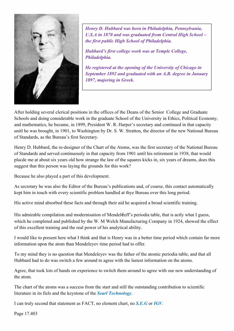
Henry D. Hubbard was born in Philadelphia, Pennsylvania, U.S.A in 1870 and was graduated from Central High School – the first public High School of Philadelphia.
Hubbard’s first college work was at Temple College, Philadelphia.
He registered at the opening of the University of Chicago in September 1892 and graduated with an A.B. degree in January 1897, majoring in Greek.
After holding several clerical positions in the offices of the Deans of the Senior College and Graduate Schools and doing considerable work in the graduate School of the University in Ethics, Political Economy, and mathematics, he became, in 1899, President W. R. Harper’s secretary and continued in that capacity unitl he was brought, in 1901, to Washington by Dr. S. W. Stratton, the director of the new National Bureau of Standards, as the Bureau’s first Secretary.
Henry D. Hubbard, the re-designer of the Chart of the Atoms, was the first secretary of the National Bureau of Standards and served continuously in that capacity from 1901 until his retirement in 1938, that would placde me at about six years old how strange the law of the squares kicks in, six years of dreams, does this suggest that this person was laying the grounds for this work?
Because he also played a part of this development.
As secretary he was also the Editor of the Bureau’s publications and, of course, this contact automatically kept him in touch with every scientific problem handled at thye Bureau over this long period.
His active mind absorbed these facts and through their aid he acquired a broad scientific training.
His admirable compilation and modernisation of Mendeléeff’s periodia table, that is actly what I guess, which he completed and published by the W. M Welch Manufacturing Company in 1924, showed the effect of this excellent training and the real power of his analytical ability.
I would like to present here what I think and that is Henry was in a better time period which contain far more information upon the atom than Mendeleyev time period had to offer.
To my mind they is no question that Mendeleyev was the father of the atomic periodia table, and that all Hubbard had to do was switch a few around to agree with the lastest information on the atoms.
Agree, that took lots of hands on experience to switch them around to agree with our new understanding of the atom.
The chart of the atoms was a success from the start and still the outstanding contribution to scientific literature in its fiels and the keystone of the Searl Technology.
I can truly second that statement as FACT, no element chart, no S.E.G or IGV.
Page 17.403

In addition to the compilation of the chart, Mt. Hubbard was author of numerous scientific papers, articles, and charts, and for many years wrote the Annual Review of Physics for the international Yearbook.
I have no knowledge upon this annual review, as I have never been in a position to studied one so far to date.
He was a leading authority on weights and measures, industrial standardisation, and atomic physics.
I understand that Mr. Hubbard married Mary Furness in 1897; sorry I could not make it to the wedding.
Children: Henry F. Hubbard and Mrs Mabel Sutherlin.
He died June 26th, 1943, amazing I were just turned 11 years and a month old then; does not time fly.
Whatever Hubbard achieved with the element chart the results played a great part in my work, thus Mendeleyev and Hubbard are part of this success story.
For without their input, they may not been a S.E.G. or I.G.V concept to day, by which reality of a new age could be born that was pollution clean, improved health, improved food, clean water to add to life pleasure.
In addition, an issue that is badly needed today the reduction of viruses and bacteria, which do not enjoy a negative charge state, would perish.
I feel that this is rather a good point to close this issue until the next time we meet to extend this discussion.
This document released by the authority of:
Prof. John Roy Robert Searl. Head of R&D Energy and Transportation System.
From the tiny acorn grows the mighty oak, likewise, a dream that child had shall grow into a multinational operation that will expand throughout the universe as no other has achieved, so shall it be!
It time for man to say STOP – THINK – ACT before it too late; where do you go when Planet Earth can no longer support you, which could happen at any time now.
That is correct – there is nowhere for you to go – WHY?
Because you failed to listen to the warnings, rivers, ditches should been dug out deep and clean where possible widen to take floodwaters, but they are not.
Thousands of trees should have been planted so by now they would had reach adulthood – but they are not.
Page 17.404
DOC-SISRC-HC-TM222-1
DATE: 23rd October 1986
EDITION: First.
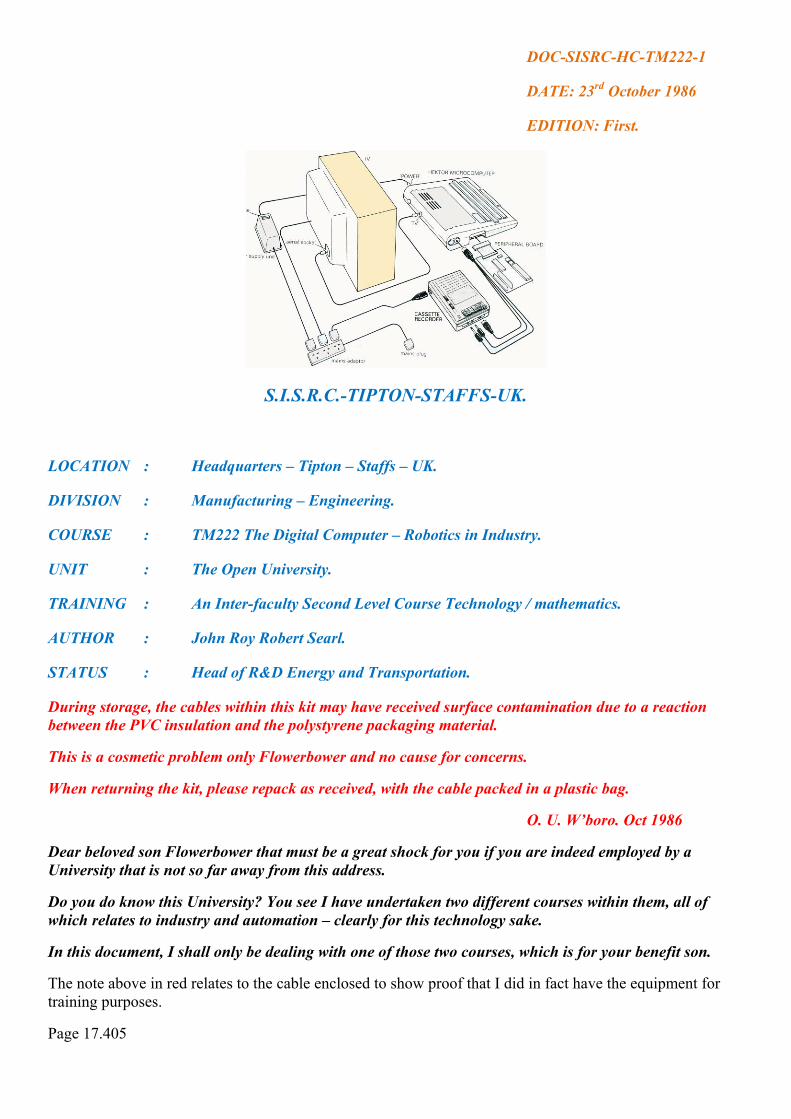
S.I.S.R.C.-TIPTON-STAFFS-UK.
LOCATION : Headquarters – Tipton – Staffs – UK.
DIVISION : Manufacturing – Engineering.
COURSE : TM222 The Digital Computer – Robotics in Industry.
UNIT : The Open University.
TRAINING : An Inter-faculty Second Level Course Technology / mathematics.
AUTHOR : John Roy Robert Searl.
STATUS : Head of R&D Energy and Transportation.
During storage, the cables within this kit may have received surface contamination due to a reaction between the PVC insulation and the polystyrene packaging material.
This is a cosmetic problem only Flowerbower and no cause for concerns.
When returning the kit, please repack as received, with the cable packed in a plastic bag.
O. U. W’boro. Oct 1986
Dear beloved son Flowerbower that must be a great shock for you if you are indeed employed by a University that is not so far away from this address.
Do you do know this University? You see I have undertaken two different courses within them, all of which relates to industry and automation – clearly for this technology sake.
In this document, I shall only be dealing with one of those two courses, which is for your benefit son.
The note above in red relates to the cable enclosed to show proof that I did in fact have the equipment for training purposes.
Page 17.405
By the way, Flowerbower you can be excused to change your underwear, I appreciate that is must be extremely uncomfortable sitting on that lump of such hot material.
Welcome to the HEKTOR microcomputer!
This manual has been written to make my use of HEKTOR as easy as possible and to provide a description of its facilities to all my readers so that you may know that I am indeed telling the truth.
The contents of this manual are divided into three parts:
1) Part 1: Introduction and set-up;
2) Part 11: Using HEKTOR’s main software facilities;
3) Part 111: Further technical information.
In more detail, the contents of this manual are:
PART 1 Introduction and set-up
Section 2 Overview of the HEKTOR system
This section describes the structure and operation of computers in general, and relates this general structure to the particular components and operation of the HEKTOR microcomputer.
There is also an introduction to HEKTOR’s system software.
Section 3 HEKTOR system set-up.
In addition to information on connecting and setting-up my HEKTOR, this section contains handling precautions and a description of how to use the built-in self-test program to check for any system malfunction.
There is also a subsection to aid diagnosis of, and recovery from, hardware faults.
For this document let me stop here and start this first section:
2 OVERVIEW OF THE HEKTOR SYSTEM:
This section contains a review of the basic structure and principles of operation of digital computers.
These general principles are illustrated with respect to the HEKTOR microcomputer system.
The section also serves to introduce some of the terminology that will be used in the later sections of the manual.
Sorry Flowerbower that I have to keep exposing you as a mentally ill person (which you are) within these permanent records and I will continue to do so until you stop your evil ways on YouTube. I will continue to ridicule you wherever and whenever the opportunity arrives.
2.1 The structure of a computer:
The overall structure of a computer can be described in terms of five principal subsystems:
Page 17.406

Figure 17.2.1 Computer structure.
1. The processor (or processing unit)
2. The memory.
3. The interfaces.
4. The peripherals.
5. The computer bus.
These subsystems are connected together electrically, as shown schematically in Figure 17.2.1.
The bus is a common highway, to which the processor, interfaces, and memory are connected.
It consists only of a set of electrical connections, but these are organized so as to allow the orderly communication of data between any of the other subsystems connected to it,
The bus is important because it offers flexibility; extra memory or additional interfaces can be added to a computer simply by connecting them to the bus – the existing interconnections do not have to be modified.
The processor organizes the fetching of data via the bus, performs operations on it, and despatches the results.
It is directed in these tasks by a list of encoded machine instructions called a program, no doubt similar to the system I used for my mass railway operation system of train control, and the unmanned Levity Discs.
One of the jobs of the memory is to hold this list of instructions, which the processor will fetch, interpret, and execute, one at a time.
The memory also holds data that will be operated on by instructions, and the results of these operations can be stored in memory for later use.
Page 17.407

The memory, therefore, is used for several different purposes.
It can retain data, which is to be operated on by machine instructions, as well as the list of instructions itself.
There is no distinction between the way in which data is stored and the way in which instructions are stored, it is the responsibility of the program designer to ensure that data in memory representing numbers to be arithmetically processed, say, is not treated by the processor as instructions in a program, and vice versa.
If the computer is to be generally useful, not only must it be able to process data held in memory, but it must also be able to communicate data to and from equipment external to the memory and processor.
Various displays, knobs, switches, sensors and actuators can be controlled or interrogated by the processor.
When connected to a computer system, these devices are called peripherals.
Because the data they supply or expect to receive is seldom in the precise electrical form required for transmission via the bus, additional electronic circuits are required to provide the necessary conversions.
These pieces of circuitry are connected between the bus and the peripherals as shown in Figure 17.2.1, and are called interfaces.
In summary, the processor (or processing unit) controls the operation of the computer, by a sequence of operations resulting from its execution of machine instructions held in memory.
Writing this chapter 17 has been a big pain in the arse for every time I go to insert a photo, drawing or table it must crash first then you can add it.
Thus you get many pages of scrap to trash for every page I attempt to write if I insert something into that page – this machine instructions sure is a mixed up kid or on drugs and it sure is time consuming.
These operations involved processing data held in memory or supplied, via an appropriate interface, by an input peripheral.
The data resulting from these processing operations can be returned to memory or sent to an output peripheral.
All date transfers between the processor and memory or peripheral interfaces are via the computer bus.
How is that Flowerbower, this is university stuff and I am not yet steamed up to race with you – that is yet to come – so keep watching – your hour of excitement with my cane is approaching as certain as apples are apples; might call this operation WACK-O DAY!
Page 17.408

2.2 The HEKTOR microcomputer board:
The microcomputer board layout inside HEKTOR can be viewed by removing the lid in the top of the case.
Figure 17.2.2 HEKTOR microcomputer board layout.
Figure 17.2.2 is a plan view of the HEKTOR microcomputer printed circuit board, showing the main components grouped into six subsystems.
The principal peripherals are a cassette recorder, which you youngest of today may not ever seen one, I had one on this kit, a TV set, which I had to supply, and a keyboard, which they supplied.
There was a massive robot, which I shall not be discussing at this moment in this part of events. I know all of you students training with this university in relation to Digital computing will have used this computer so you know what I am saying is absolute true.
Of these, only the keyboard is mounted on the HEKTOR board itself.
In Figure 17.2.2, the keyboard is at the bottom.
The line around the keyboard shows the area of the board that includes the keyboard and its interface.
The keyboard interface consists primarily of the component labelled IC14, and it connects both to the individual keys on the keyboard and to the microcomputer bus, which consists of some of the copper printed circuit tracts in the area of the board labelled ‘processor / bus’.
Page 17.409

The processor is IC13 in Figure 17.2.2, and it requires a few extra electronic components around it to enable it to operate.
However, most of the area of the board is taken up with the bus tracks, which goes to the edge connector (between the slots at the left hand side of the processor / bus area).
The edge connector enables peripheral interfaces or memory external to the main HEKTOR board to be connected to the microcomputer bus.
The memory subsystem includes IC7, IC12, and SKT0 TO SKT5, in Figure 17.2.2.
The interface components for the cassette recorder are shown in the top left hand corner.
The recorder itself is connected to its interface by means of the socket labelled SKT7.
There is also a general-purpose serial line interface in this area of the board, which enables a wide range of peripherals (such as printers) to be connected via SKT6.
Above the memory subsystem, in Figure 17.2.2, is the TV interface, which connects via SKT9 to the aerial socket of a standard UHF TV receiver.
The remaining components on the board, at the top and right, are part of the power supply for HEKTOR.
Mains power, transformed down to a lower voltage, connects to SKT8, from where it is converted into a stable DC electrical supply required by the electronic components on the HEKTOR board.
2.3 Inside the processor:
Figure 17.2.3 Structure of the processor.
Figure 17.2.3, is a simplified diagram of the internal structure of a processor (of which the 8085 microprocessor in HEKTOR is a typical example), all my data upon this microprocessor I feel certain that Martin and Ken took it.
Page 17.410

The processor contains four main groups of components:
1. The registers.
2. he arithmetic / logic unit (ALU) T
3 The control unit.
4 he internal bus. T
Of these components, the internal bus (like the microcomputer bus of the computer as a whole) acts as a common intercommunication facility for the other components. The registers hold data within the processor. Some hold data for a specific purpose related to the operation of the computer, and others are available for general use by the program designer as a small but convenient memory. 2.3.1. The arithmetic / logic unit: The arithmetic / logic unit is shown in Figure 17.2.3, as the ALU. It is the ALU that performs an actual processing operation on data, as directed by a machine instruction following its fetching into, and interpretation by, the control unit. Suppose two data items, each representing numbers, are being added together; a typical processing operation. One of the numbers to be added is assumed to be stored in the accumulator register; the second number may be in one of the general registers in the register array. The machine instruction calling for the addition operation will specify which general register. In interpreting this instruction, the control unit will first cause the second number to be copied into the temporary register, via the internal bus. The ALU will then perform the addition, usually returning the results – via the internal bus – to the accumulator, where it replaces the original number. The result of the operation is avail – in the accumulator. but it is also useful to have a summary of the features of the results. This is the purpose of the flags in the flag register. There is a flag – a simple yes / no indicator –, which indicates whether the result was zero, or not, another which indicates the sign of the results – positive or negative - , and so on. Other machine instructions can test individual flags and behave accordingly. Thus, it is possible to execute one sequence of instructions if the result of a previous addition is positive and a different sequence if the result was negative. The ALU can be instructed to perform a variety of arithmetic operation such as addition and subtraction, and Page 17,411

Logical operations such as AND and OR. There are, of course, separate machine instructions for each type of operation, and different processors have different instruction sets. However, these simple operations available in the instruction set can be combined by the programmer so as to provide arbitrarily complex processing operations. Multiplication, by repeated addition, is one example. 2.3.2. The program counter:
Figure 17.2.4 Figure 17.2.5 fetching an instruction. Figure 17.2.4. Memory locations and addresses. One of the registers in the register array of Figure 17.2.3 has a single special purpose. It is called the program counter, and it holds information specifying the location in memory of the next machine instruction to be executed by the processor. The memory consists of a collection of identical memory locations, each of which can hold a piece of data or part of a machine instruction. In most microcomputers, a machine instruction occupies one, two or three adjacent locations. Each location is identified by a unique number called its address, and consecutive locations in memory have consecutive addresses, as shown in Figure 17.2.4. If that is true then one unique, number is missing in a program by which you can insert data from the desktop into it. Suppose that the list of instructions forming a program is stored in an area of memory, and that the first instruction in the program – that is the one occupying the location with the lowest address – occupies the single location with address 100. In order to execute this program, the program counter – or PC register – must contain the address 100. The first action of the processor in executing this program is to communicate the address in the PC to the memory subsystem, via the address part of the computer bus – see Figure 17.2.3. Page 17.412

How this address can be stored in the PC will be discussed later. The memory responds by communicating the information stored in the address location back to the processor via the data part of the computer bus. This information is stored within the control unit of the processor as the machine instruction it is to execute. This fetching of an instruction summarized schematically in Figure 17.2.5. The instruction is then ready for interpretation and execution by the control unit of the processor – possibly using its ALU However, the control unit, before executing the instruction, increases by one the number stored in the PC register. Then, having completed the instruction execution, the PC will be ‘pointing’ to the next location in memory, which in this example has the address 101 and contains the second instruction in the program. The second fetch / execute sequence can then begin automatically. Some machine instructions may occupy two or three memory locations. Likewise, with my rail way lay out every signal contained a memory cell; every train had codes to identify itself to the signal memory unit. It then identify the train than fetch the instructions from the main memory and executed such machine codes it received in to functions as points closed = 0: points open = 1: power ground = 0: power overhead = 1: and so on to cover all possibilities. In these cases, there are extra ‘fetches’ with the PC contents increased by one each time, before the ‘execute’ phase of the sequence. For much of the time, the instructions in a program are fetched and executed in the order that they are stored in memory. However, sometimes, the programmer will want to interfere with this natural sequence. An example already mentioned is that of using the value of a flag to decide which of two sections of program should be executed next. A simple instruction, which enables the program sequencing to diverge from the natural order, is the jump type of instruction. This instruction includes a memory address. When the instruction is executed, the address part of the instruction is simply stored in the PC register. Then, as the processor moves on automatically to the next fetch / execute sequence, the new instruction will fetch from the location whose address specified in the jump instruction. NOTE: the reason why I am covering it is to prove that I understand what I am doing in both the IGV and the Rail control systems; automation, I have always accepted as the key to future progress: I understand many do not understand this need. Page 17.413

2.3.3. The control unit:
The control unit – Figure 17.2.3 – of the processor already mentioned in the context of the interpretation of machine instructions.
The control unit issues the sequence of electronic signals, which trigger the transfer of data of all types both inside and outside the processor.
For example, within the processor, they cause the transfer of data from a general-purpose register to the temporary register.
Other control signals define which operation, of the several available, is to be performed by the ALU during the execution of a processing instruction.
Similarly, the control unit issues control signal sequences on the control panel of the computer bus Figure 17.2.3, which enable properly timed data transfers between the processor and memory – or interfaces.
This timing aspect of the control signals is achieved by the use of a clock signal, a regularly space sequence of electrical pulses or ‘ticks’.
Consider again the instruction fetch sequence of Figure 17.2.5.
At one clock tick, the control unit will cause the PC’s contents to be made available on the address bus.
Clearly, it will take some time before the memory can respond by placing the required machine instruction on the data bus.
Therefore, the control unit will wait for one or more clock ticks before accepting the instruction from the data bus.
Besides timing this data transfer, the control unit will have to define the direction of data transfer.
One of the signals making up the control bus indicates to the memory whether the addressed location is to have data read from it or written into it.
That is, is the direction of data transfer to the processor from the memory, or vice versa?
Besides the control, bus signals that allow for the orderly transfer of data via the bus, there is another group of signals, which enables events outside the computer to influence the normal sequence of program execution.
These are termed interrupt signals.
When the control unit of the processor receives an interrupt signal, it suspends program execution – after completing the execution of the current instruction – and performs some special action, depending on which of several types of interrupt is received.
Typically, the interrupt will be a request for attention from some peripheral device, and the effect of the interrupt is similar to that of a ‘jump’ instruction; that is, the processor starts executing a separate piece of program called an interrupt handler, which will perform the operations required by the peripheral device.
A special type of interrupt is the reset signal.
This signal is generated automatically when the computer is first switched on – and there also may be a reset switch that the computer operator can use.
In HEKTOR, the reset signal sets the PC contents to zero, thus enabling the program, which is stored in memory at address zero to be executed.
Page 17.414

This solves the problem of how to set the program counter to a known address, a necessary preliminary to allowing the automatic fetch / execute sequence of the processor to take control of the computer. Bank upon this document, you ought to be able to judge if or if not I could had created a railway display fully automatic operation or not. The unmanned models of the Levity Disc operated on a critical sequencing of functions required for perfect operation. So far, you have still only read a small amount of Searl’s life and work, his knowledge and interest all adds up to show that the subject matter is based on reality (or fantasy if you prefer); you make the choice. This document released to the public by the authority of:
Prof. John Roy Robert Searl Head of Human Studies. Automation and Robotics for the advancement of the Searl Technology. The Searl Effect Generator (S.E.G) and Inverse-Gravity-Vehicle (I.G.V). To all those who have requested details of my life in the Midlands, as most of you have never read all my books which I have written, I will just insert a few maps covering the area I worked and lived, please note that Hollywood ran out of time so they never got around to cover Suffolk or the Midlands areas.
A district I knew well as I cover 11 districts within my work: on this map above I got my coco three times a week and boy it sure was hot. Page 17.415

These maps cover all the articles written by me about my time before I married and then later after I left my Mortimer home and return to this district that is correct Roy.
I know that Princes End: where I meet my wife after 31 years I wished I had left here there, is most likely vanished by now the line of toilets at the back of the garden, A shed no door to wash just cold running water, yes I sure know that area.
I took my property owner to Wednesbury court charged her with stealing my property while I was serving in the military.
West Bromwich, yes I work as submarine seamless pipes inspector to pass or fail them, Also worked at Carters green cinema, now no longer a cinema but it was then in 1952.
Great Bridge, yes lived there used the market place for food evenings work second job as projectionist at the cinema there.
Page 17.416

DOC-SISRC-MFD-AP-5.
DATE: 1st January 1975.
EDITION: First.
SWALLOW COMMAND-MORTIMER-BERKSHIRE-UK.
LOCATION : Headquarters-Mortimer-Berkshire-England.
DIVISION : Manned Flight.
SENIMAR : Air Accidents Tables 5, 6 and 7.
AUTHOR : John Roy Robert Searl.
STATUS : Head of R&D Human Studies.
My sincere thanks to the Civil Aviation Authority, who compile this data that played a major role in the studies in the design of the Inverse-Gravity-Vehicle (I.G.V) ; without this data I would not known of these problems with conventional aircraft.
As stated, I am only using one whole year of air accidents as a model relating to structure failure that year selected was 1971.
Structures for flight often are cut close to the thin line of no go and go, which means as long as no problem occurs the structure holds good, but if problem occur then structure cannot cope with the surge of energy it needs to disperse, therefore it disintegrates.
Todays heavy passenger’s aircraft making a bad touchdown, are more likely to suffer material fatigue, which could and often does cause actual destruction of the aircraft as a whole, which is without question no good for your health.
Understanding these problems, as to how to disperse sudden surges of energy is a major issue, which applies to all transportation systems regardless.
To that of material problems, you also have to add those of human life that needs to be coping with.
Page 17.417

TABLE 5. ACCIDENTS CLASSIFIED BY PHASE OF OPERATION AND NATURE OF FLIGHT:
Hello Flowerbower yes I am watching you watching me watching you, how are you son you beautiful flower, this is my world of reality – not your world of insanity.
Keep watching over your shoulder if you see a man with a cane in his hand, that’s I; the can is searching for your arse to give it the best welcome it has ever experience in its life.
That sure will be a great day for your arse, I know where you are, as stated I am playing a game with you, just for now.
You pick the wrong man when you pick me for your poison pen letters, as you will discover that I do not treat evil people kindly.
I have delivered this data upon aircraft accidents in blocks, mainly to avoid boring readers, and yet to show the truth what I was involved in at what times and where, in answer to all who wrote me about evil claims against me what am I going to do, you have to answer them
That is precisely what this book on the web is about placing in the public domain the facts involving the past wherever it is possible to recover the facts, what is involved today, and what our plans for the future are and if funds are available, where are the workplaces and the workforces.
Therefore, this story has no ending because it is a living story of reality, which will continue after I have gone for good, because it is the future that is meant to be, the dreams of men and women for knowledge and a better life than presently exists on planet Earth.
Page 17.418

TABLE 6 ACCIDENTS CLASSIFIED BY TYPE OF ACCIDENT AND NATURE OF FLIGHT:
As a matter of interest upon the question of when did I first went airborne; the answer is simple it was from Birmingham to Northolt London with my wife on coronation day of our present Queen.
I know why you said the Lord’s Prayer before taking off – the landing was so bad that a drunk could had done a better job of it – he must had landed with his eyes shut – then it was an Irish crew, what can you expect!
Page 17.419

TABLE 6 ACCIDENTS CLASSIFIED BY TYPE OF ACCIDENT AND NATURE OF FLIGHT (Continued)
Sorry just remember that was not my first airborne trip, I had flown before I ever meet a girl. From North holt London to Dublin, then I discover why the need to say the Lord’s prayer before take off.
The landing was so heavy a drunk could had done a better job of it, he must had tried to show he could land with his eyes shut; then it was an Irish crew what else could I expect; clearly the cabin crew had grown use to it and consider it just a bumper car practice.
If you think that was bad – you are wrong – you should had been on that bus that took me from the airport to Dublin centre.
The driver must had fancy himself driving a gaint amour tank in the front line as he ripped down the center of the road at speed as if his arse was on fire, a mircle – by heavens it was that I got there in one piece.
When he stopped I continue on my way, which prove not a good idea as I tried to pass through metal wall, which are possible for spirits to do, but not for the living.
I returned by sea; by the St. Patrict to Hollyhead then train back to London, which I considered a safeter route, and it was.
Page 17.420

TABLE 7 ACCIDENTS CLASSIFIED BYAPPARENT CAUSE AND NATURE OF FLIGHT:
Yes, I expect you are surprised on how accidents happen, my problem is solving why they actually happen and what can be done to see that SWALLOW COMMAND do not make such errors in their operations.
Page 17.421

TABLE 7 ACCIDENTS CLASSIFIED BY APPARENT CUSE AND NATURE OF FLIGHT: (Continued)
These are not good records for any company to have attached to them, and SWALLOW COMMAND must see that their operations never ever are listed in any one of these reports as shown in this book, not even if they do fly conventional aircraft from time to time.
Page 17.422

TABLE 7 ACCIDENTS CLASSIFIED BY APPARENT CAUSE AND NATURE OF FLIGHT: (Continued)
Here we see a problem that some accidents leave no clear indication as to why it happen, and therefore no solution can be offered to prevent such happening again – or was it an pilot error.
Page 17.423

TABLE 7 ACCIDENTS CLASSIFIED BY APPARENT CAUSE AND NATURE OF FLIGHT: (Continued)
This completes seven tables so far within this book, dealing with accidents in 1971 from which I can obtain a mental picture of the problems, which have occurred.
Taking off engine could fail; I accept that as possible, what my mind question is why did it.
Was the climb out far too steep for the load being carried?
Alternatively, was it fuel related problem, I was lucky that engine failure never occurred during all my flying hours.
Page 17.424

DOC-SISRC-MFD-N-G-1
DATE: 15TH December 2008.
EDITION: First.
SWALLOW COMMAND – GLASGOW-SCOTLAND.
LOCATION : Headquarters – Glasgow – Scotland.
DIVISION ; Medical-Manned Flight.
SEMINAR : Alcohol, Nutrition and Sea Urchins.
AUTHOR : Prof. John Roy Robert Sear.
STATUS : R&D Human Studies.
In this release; I shall re-do three passed subjects in the effort to help you to understand what I am involved in, or connected with.
I may not be in any kind of sport, no interest at all, far too busy worrying about you and your future families that might appear that they may have hope in the future to see a better life than you may be experiencing at this time.
The one thing which gets my goat is people like George Best who had an alcohol problem was given a new liver – why on earth waste time and money plus a organ that are in short supply on a person like that, who I knew would destroyed it did not require intelligence to identify that would happen.
I would never give a liver to a person suffering from alcoholism; they achieved that condition by show off then let them show off what dying is like as an alcoholism state death.
Alcoholism is a disease and it is unfair to give a liver to someone who will not look after it.
In fact, it is an insult to people who have given their organs hoping to do good.
It makes me think twice about being on the donor register; I would be very upset if my organs went to someone who had already wasted their own.
However, how far down the track do we go with only treating worthy causes?
I think more people would donate if they knew their parts were going to a good home.
One minute we are being asked to consider the opt-out scheme, next thing we hear negative stories like this may well put many people off donating their organs; I do not really care – when I am dead, I will not need them anymore.
Page 17.425

Human Facts.
Sea urchins share many of the same genes as humans. On the face of it, it seems an unlikely cousin.
The spiky underwater invertebrate more closely related to people than are flies or worms, and share more than 7000 of the same genes.
Within an urchin’s DNA is closely associated with human disorders; including muscular dystrophy and Huntingdon’s disease.
Other genes include those that humans need for taste, smell, hearing, balance and perhaps most surprisingly, vision.
Sea urchins can apparently see, or at least sense light, through their feet.
Another unexpected find was that sea urchins have a unique and complex immune system, which in some respects out performs those of much more advanced animals.
Experts have identified 23,300 genes made from 814 million strands of DNA taken from the California purple urchin.
One of the biggest shocks was the discovery that the creatures have inate sense of vision.
These organisms have been looked at for 31 years or more and now we know all that time they were looking back at us. No one would have predicted that sea urchins have such a robust gene set of visual perception.
The creature has been widely studied for many years. They lay millions of eggs and their transparent embryos reveal all their working parts.
Humans have about 100,000 genes.
Therefore, when you jump into the bed and find your girlfriend all prickly you will understand why that she has more sea urchins genes than female human genes in her makeup, but watch out for her feet that might have vision capability.
This might not interest you, but it does to me as there are far too many children and adults who have damaged genes because their parents were not check to see if they were ok to bred and have passed on damaged genes.
If we could mass-produce these creatures; at a rate that could generate sight for the blind and other improvements for life that would be a wonderful achievement.
This also can apply to other animals that we kill for food chain, if they grew human parts in place of their present parts; would be a great achievement in giving those who suffer a better lease on life.
What about the blood, if we could mass-produce it, think of the lives it can save these days.
The problem of deep space exploration, any major accident with flight crew, they will depend on what materials are available to save life onboard; we must learn and understand ourselves in terms of reality and not baby talk of fantasy.
Page 17.426

NUTRITION IS ESSENTIALLY A VERY SIMPLE THING:
Eggs are not such bad things and are a better friend to have than a kebab or a Viennese whirl.
I have stated so many times what a track record our experts have, before I remind you of this one let me make it clear when I can afford eggs I eat them every day regardless.
After years of being falsely accused of causing heart disease and clogging arteries, the good old-fashioned egg has been enjoying its recent releases from the Unhealthy Food Club, where it shared a cell with high-fat cheese and the potato waffle.
The egg is now at the gym with its old friends the mackerel and the blueberry.
Yogurt tried to join but was turned away after a dispute about how much fat it contained.
I have to admit that I was never one for yogurt.
Nothing gets past the healthy food police.
Nothing, except the obvious.
Just let me remind you of my young days that is fifty years ago, a successful advertising campaign urged us to go to work on an egg – so I went to work on two eggs.
Decades later, as our knowledge of nutrients, cholesterol and saturated fats grew; we began to label what we ate, I found the labels did not taste very good.
However, they were useful, as the waste out got label, use in 4 days once defrosted.
In addition, that was when the humble egg was rebranded from natural source of protein and vitamins to potential bringer of Death.
It’s OK said the experts, if you have two a week but any more and you will risk raising your cholesterol – and we all know that cholesterol is bad.
In addition, as usual new research tells us this was all rubbish that is not news to me, I knew that so I started eating two eggs a day, and still do when I can afford to buy eggs.
Eggs do not raise Cholesterol levels.
Eggs in fact are not such bad things and are better friend than a Kebab or a Viennese whirl, which so far I have never tried a kebab whatever they are but I have been naughty and have eaten 6 Viennese whirls secretly, so please don’t tell anyone what I have done, we will keep it a secret.
I will avoid the obvious route here and not poke fun at the pursuit of temporary truths that is evidence-based health care.
Suffice to say that research – no matter how robust – is really no substitute for thinking.
Instead, I invite you to chat about the exciting near-science of nutritionism, which is the process of understanding and meeting the nutritional needs of people including SWALLOW COMMAND flight crew of long mission durations in deep space.
Its emergence has led to technicians playing with all sorts of previously dull foods to ensure they contain
Page 17.427

more omega-3 or less saturated fat.
Nutritionism says the key to understanding food is examining and reorganising its nutrients.
That does not say that I am convinced they are right.
Now, I don’t have anything against nutritionists and I don’t mind omega-3but, as healthcare professionals, shouldn’t we be cautious of intervening too much?
Nutrition is fundamentally a simple thing, summed up wonderfully by the American writer and campaigner Michael Pollan: Eat food.
Not too much.
Mostly plants.
Like others, he is concerned about the industry we have constructed around the inventing, processing and marketing of foodstuffs.
All future nurses who will be employed with the Searl International Space Research Consortium complex will know changing unhealthy habits is difficult, and that an ever-shifting evidence base makes for complex and contradictory messages.
Food is better than foodstuffs.
Plants are better than processed stuff.
Meat and fish are probably fine if you do not fill them with rubbish before you kill them.
In addition, eggs?
Eggs are fine.
This is just common sense, isn’t it?
In addition, wasn’t that always the nurse’s best friend?
This is just one of hundreds of problems, which must be solved before mans journey to Mars and beyond can commence as a business.
I hope you have enjoy reading this issue, and many more issues will be aired, things are moving faster today in trying to solve problems then every before, man will travel on long term missions in space, but we are not yet quite ready for that day.
This document released to the public by authority of:
Prof. John Roy Robert Searl. Head of Human Studies.
Medical Division – Manned Flight/
Page 17.428

DOC-SISRC-MFD-MM-FP-T2
DATE: 7th July 1965
EDITION: First
SWALLOW COMMAND-MORTIMER-BERKSHIRE-UK
LOCATION : Headquarters-Mortimer-Berkshire-England.
DIVISION : Manned Flight.
SUBJECT : Mariner-Mars 1964 – Trajectory.
AUTHOR : John Roy Robert Searl.
STATUS : Head of R&D Human studies.
THIS IS THE CONTINUE ARTICLE FROM CHAPTER 16.
EARTH-TO-MARS TRAJECTORY CHARACTERISTICS:
For the best utilisation of the available rocket energy, the relative motion and position of the planets about the Sun must be considered, since the spacecraft itself, once freed from the Earth’s gravitational pull, becomes a member – planetoid – of the solar system and, therefore, subject to the same inertial forces.
As a result of the changing planetary relationships, the available time departure – launch date -, the speed of travel, and the time of the flight, and the flight path change continually.
Of prime significance in scheduling, an interplanetary trip is the knowledge that a free-falling – orbiting – body travels in an imaginary plane, which passes through the centre of a controlling body.
For an Earth-to-Mars interplanetary spacecraft, this controlling body is first the Earth, then the Sun, then Mars, and again the Sun.
Within each of these planes, the spacecraft follows certain geometric paths that are mathematically definable and predictable.
The trajectory path describes various conic figures: Earth orbit: ellipse; Earth escape: hyperbola; Sun-centred transfer orbit: ellipse; Mars encounter and escape: hyperbola; and Sun-centred permanent orbit: ellipse.
Near-Earth Ascent:
Well Flowerbower you are about to learn more about reality then you know at this date.
I will start this next statement on the next page because I do not wish to break it up into sections.
Page 17.429

Figure 17.2.1 Typical near-Earth ascent trajectory profile – in near-Earth ascent trajectory plane – for Mariner – Mars 1964 spacecraft.
The ascent phase for mission – Figure 17.2-1 – could by divided into three portions:
1. The power-flight ascent;
2. The parking-orbit coast;
3. The post injection ascent.
The powered-flight ascent consists of the Atlas D and Agena D thrust periods. At the end of the first Agena D thrust period, the Agena D / spacecraft combination is placed in a nearly circular parking orbit at an altitude of approximately 188 km – 117.5 statute miles -.
The Agena D / spacecraft combination “coasts” in this orbit until the optimum point is reached for a final thrust phase – near perigee or closest point of the required escape hyperbola - , at which time the Agena D thrust period and, consequently, when the spacecraft is “injected” into its hyperbolic orbit away from the Earth.
The post injection ascent describes an escape hyperbola with the Earth’s center as its principal focus.A characteristic of the escape trajectory is that after a few hours the spacecraft travels essentially radially away from the Earth along the outgoing asymptote of the escape hyperbola.
This asymptote is a straight line parallel to the outgoing radial – a straight line connecting Earth’s center and the geocentric point in space at which the spacecraft finally escapes the pull of the Earth’s gravitational field-
How about that Flowerbower, can your sarcastic brain comprehend yet and accept with my understanding of reality? Regardless, here everyone can see that you must be just a paid troll on YouTube with an evil streak.
Page 17.430

The spacing between these two lines is determined by the eccentricity of the hyperbola, which is, in turn, determined by the velocity of the spacecraft at the time of injection.
The direction of the outgoing radial is defined by its celestially referenced right ascension and declination.
The value of the right ascension and declination is determined from the relative positions of Earth at launch and Mars at encounter, and remains essentially fixed for a given launch date.
Since the launch site remains at a fixed geographic latitude, the requirement of the near-Earth ascent phase is to match the powered-flight portion – which begins at the launch site – to the required escape velocity vector.
The direction of this vector is determined by the asymptote of the escape hyperbola.
The hyperbolic excess velocity is the geocentric velocity – the velocity in relation to the Earth’s centre –, which the spacecraft attains a few days after launch as it becomes free of the gravitational pull of the earth.
The magnitude of this velocity is proportional to the square root of the injection energy.
The outgoing radial and the geocentric position of the launch site define the plane of the near-Earth ascent trajectory.
The injection energy – that energy required to effect the ballistic transfer from Earth to Mars – is at a minimum every 25 months.
This time period is determined by the harmonic relationship between the duration of time required by Mars and the Earth to complete their orbital revolutions about the Sun – approximately 687 and 365 days, respectively.
Any launch other than one at optimum time requires an increase in injection energy and a resultant decrease in allowable spacecraft weight.
For a given spacecraft weight, there is a corresponding value of injection energy which is achievable by the launch vehicle.
For any available energy above the absolute minimum, there is a corresponding launch interval – number of days – in which the spacecraft can be launched.
Each day in this launch interval has its own launch period or “window” of only several hours or minutes.
This launch window results from several interrelated restrictions and conditions:
1. The geographically fixed launch site on the surface of the Earth.
2. The Earth’s centre point.
3. The geocentrically referenced location and direction of injection into an Earth-escape hyperbolic orbit.
The range of locations and directions varies with celestial latitude of Mars at encounter and with Earth’s own orbit position and, therefore, does not change significantly for any given day.
4. The rotation of the Earth about its axis.
5. The 930 to 1110 East of true North – North referenced to the Earth’s axis rather than to the magnetic poles – geographic launch range or corridor.
Hello, Flowerbower, are you still there or has your illicit brain overloaded and shut down? Well we all hope so, if it prevents seeing your nonsense and sanity on YouTube.
Page 17.431

This is an Air Force Eastern Test Range – AFETR – safety restriction to minimise the hazard to populated areas below the launch vehicle ascent path.
The parking-orbit coast time decreases as the time of launch is delayed during a daily launch window, since the angle between the launch-site position vector and the outgoing radial – projected backward – gets smaller as the Earth rotates.
The change in both launch azimuth and parking orbit coast time results in a wide geographic range of injection locations.
The effect of the Earth’s rotation is to move the launch site eastward 15 degree hour and to change continuously the required launch azimuth to coincide with the continuously inclining spacecraft orbit plane.
This is why the Inverse-Gravity-Vehicle (I.G.V) has an advantage over the rocket concept of space travel.
The launch site, Earth centre point, and asymptote of the escape hyperbola will all be in the orbit plane of the spacecraft when the location and direction conditions of injection are satisfied.
Since the launch azimuth, increases as the time of launch increases, the period of time during a day is limited, which the required range of azimuth headings is available.
This period of time defines the launch window.
Heliocentric Transfer:
The heliocentric – Sun-centred – transfer orbit is an ellipse that essentially intersects Earth at launch and the planet Mars at encounter, with the Sun at one focus.
The hyperbolic excess velocity vector and the Earth’s velocity vector about the Sun add vectorially to determine the velocity at which the spacecraft is launched “forward” from the Earth’s orbital velocity, the magnitude of the spacecraft’s resultant velocity vector is larger – relative to the Sun - than that of the Earth’s velocity vector.
As the spacecraft then travels outward from the Sun, it decreases in speed and the Earth finally passes it – as viewed from the Sun -.
The minimum velocity required to escape the pull of the Earth’s gravitational field is approximately 11.18 km / sec – 6.95 statute miles / sec -; the actual velocity required to reach Mars is approximately 11.44 km / sec – 7.11 status miles / sec.
The additional velocity is necessary to move the spacecraft out further away from the Sun and to displace it from the ecliptical plane – the orbital plane of the Earth as projected on the celestial sphere1 – on a trajectory suitable for intersection of the orbital plane of Mars – as projected on the celestial sphere – at the optimum time for planetary encounter. 1An imaginary sphere of infinite radius, with the observer at its centre, on which all celestial bodies except the Earth appear to be projected.
Mars Encounter:
During the encounter with Mars, the primary source of gravitational attraction is the planet itself.
The trajectory of the spacecraft is similar to that during the near-Earth ascent phase – both described by hyperbolas -, except that during Mars encounter the spacecraft travels along an incoming hyperbolic path.
In addition, the altitude of closest approach to Mars is several times greater for the Mars encounter phase than for the near-Earth ascent phase.
Page 17.432

Heliocentric Orbit:
After Mars encounter and a hyperbolic escape from the gravitational pull of that planet, the spacecraft begins a new heliocentric orbit.
The parameters of the new elliptic orbit differ greatly from those of the preencounter orbit because of large inertial perturbations introduced during the encounter.
Summing up: it would be best that the Inverse-Gravity-Vehicle (I.G.V) should once clear of Earth’s atmosphere increase velocity to 9.00 statute miles / second and once clear of Earth’s gravitational field increase velocity to 12.00 statute miles / sec to push away from Sun.
MARINER-MARS 1964 TRAJECTORY DESIGN:
Determination of Launch Interval and Arrival Dates:
In order to determine the acceptable launch intervals and trajectory characteristics for the Mariner-Mars 1964 mission, studies of the relationship between flight time, launch date, and injection energy were required.
Six major factors had to be considered in the preliminary trajectory design:
1. Desire for scientific data gathering during a close flyby and transmission of the data back to Earth.
2. Use of the Atlas D/Agena D launch vehicle and an approximately 189 km – 117.5 statute mile – nearly circular parking orbit.
3. Launchings of two spacecraft with at least a two-day separation in arrival dates.
4. Launchings from two separate launch pads with a maximum launch azimuth spread of from 900 to 1140 east of true north.
In order to maximise the probability of launching two spacecraft, it was necessary to maximise the size of the launch window and thus the launch corridor.
Therefore, permission was granted for a launch corridor of 900 to 1140, instead of the usual 930 to 1110.
5. Use of an attitude-stabilised spacecraft: with the Sun and the star Canopus as reference bodies.
6. A maximum allowable Earth-spacecraft communications distance of approximately 250 million km – 156 million statute miles.
Two possible types of trajectories may be used:
Page 17.433

The type 1 trajectories are characterised by a heliocentric transfer angle of less than 1800 from launch to encounter.
The total transfer angle for type II trajectories lies between 1800 and 3600.
Longer flight times and communications distance at encounter are allowed by the type II trajectories.
In order to increase the probability of launching two spacecraft, a launch period composed of both type I and type II trajectories was selected to provide a maximum number of launch of launch days.
The two types of possible trajectories are represented in Figure 17.2-2 and 17.2-3 as two sets of closed contours.
Figure 17.2.2. Time of flight as a function of launch date.
As may be seen, the energy contours for both types provided overlapping flight times and communications distances at encounter.
Page 17.434

Figure 17.2.3. Earth-Mars communications distance as a function of launch date.
After careful study of all possible trajectories, a decision was made to use those with small variations in arrival dates.
Page 17.435

Since the relative positions of Earth, Mars, and the Sun are fixed for a given arrival date, the selection of constant arrival-date trajectories allowed the use of a fixed high-gain antenna on the spacecraft.
Also, because of the relatively constant spacecraft approach direction and velocity, the use of a fixed aiming point was permitted.
A single arrival date was not allowable, however, because of the requirement for a separation of at least 2 days between the Mars encounter of each Mariner-Mars 1964 spacecraft.
The 1965 arrival dates selected – July 15 and 17 for type I trajectories, July 17 and 19 for type II trajectories – resulted in trajectories with near minimum energy for each launch date – Figure 17.2.4. In addition, insured that a maximum possible launch interval would be available once the spacecraft were built and the maximum injection energies attainable were calculated.
Launch Date,
Figure 17.2.4 Geocentric injection energy as a function of launch date.
The communications distances at encounter for the selected dates varied from 217.5 to 221.7 million km – 135.2 to 137.8 million statute miles.
It was felt at that time that the maximum communications distance would be 251 million km – 156 million statute miles, reached approximately 25 days after encounter; thus, sufficient time would remain after encounter for two complete transmissions of the television picture data.
During the actual Mariner IV flight, however, telemetry contact was maintained to a distance of approximately 309.2 million km – 192.2 million statute miles – on the 78th day after encounter.
Because of the direct relationship between the injection energy achievable from the launch vehicle and the weight of the spacecraft, a trade-off between the length of the firing period and the spacecraft weight existed.
Page 17.436

Figure 17.2.5 Definition of B∙T, B∙R system.
Once the spacecraft weight of approximately 261 kg – 575 lb – was established, a launch interval of approximately 27 days was calculated.
Aiming Point Determination:
Studies were also to determine the region near Mars most desirable for flyby.
This aiming point could be specified by a vector B directed from the center of Mars to the point at which the incoming asymptote pierced the T-R plane.
This plane, shown in Figure 17.2-5, is defined to be normal to the incoming asymptote of the spacecraft approach hyperbola, T is a unit vector parallel to the ecliptic plane, and R is normal to T.
The aiming point is usually defined by its two components B∙T and B∙R or by its magnitude B – from the center of Mars – and the polar angle φ measured from T to R.
Spacecraft design and planetary-science-experiment consideration imposed numerous constraints on the selection of the aiming point; among the more important constraints were:
1. The Sun-probe – spacecraft – near limb of Mars angle – SPM – had to be greater than 0 during the entire encounter phase, since the Sun served as both a power source and a reference body for the attitude-control subsystem.
0
Thus the aiming point must be outside the SPM = 00 contour in Figure 17.2.6 – calculated for a November 15, 1964, launch.
2 No part of Mars or its Moons could fall within a region ±260 in clock angle and 920 ± 360 in cone angle during the encounter phase so that Canopus would be the only detectable body within the
Page 17.437

Figure 17.2.6: Aiming point and constraint regions for type I trajectory launch with a November 15, 1964, launch date, and a July 15, 1965, arrival date.
Canopus-sensor field of view: - the Canopus-probe-near limb of Mars angle - CPM – had to be greater than 360 during the entire encounter phase.
Therefore, the aiming point must be outside the region defined by CPM = 360 in Figure 17.2.6.
3 It was desirable for the spacecraft to pass within 40,200 km = 25,000 statute miles of the surface of the planet to insure a maximum scientific return from the fields and particles experiments on the spacecraft and the desired picture resolution from the television experiment.
4 The aiming point had to lie between 00 and 900 from the T-axis in the T-R plane – Figure 17.2.5.
This constraint was necessary to ensure that the planet would fall within the field of view of the planetary-scan system and to provide a picture trace across a desirable region of the planet.
Page 17.438
5 The Earth-probe-near limb of Mars angle – EPM – had to be less than 00 sometimes during the encounter phase to enable the spacecraft to pass behind Mars – as seen from earth.
Then the occultation experiment could be performed to determine the characteristics of the Martian atmosphere.
Thus, the aiming point had to lie within the region defined by EPM = 00 in Figure 17.2-6.
6 The probability that the spacecraft would impact Mars had to be less than 10-4.
Therefore, the region defined by impact probability – IMP = 10-4 in Figure 17.2.6 had to be avoided.
After careful consideration of the constraints, aiming points were selected to lie on the centreline of the Earth’s occultation contour with B = 12,068 km – 7,500 statute miles.
Since the centreline varied slightly with trajectory type and arrival date, the aiming point would change slightly also.
The precise arrival time had to be selected also and was chosen so that the spacecraft could be viewed by the Goldstone Deep Space Communication Complex during the encounter sequence.
Since the television sequence was designed to occur before closest approach, the arrival time – defined as the time of closest approach to Mars – was chosen to be 1 hour past the middle of the Goldstone-view period.
I will break at this point; one can see the task involved to plan a trip to Mars, certainly not on a credit card.
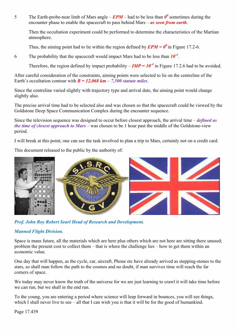
This document released to the public by the authority of:
Prof. John Roy Robert Searl Head of Research and Development.
Manned Flight Division.
Space is mans future, all the materials which are here plus others which are not here are sitting there unused; problem the present cost to collect them – that is where the challenge lies – how to get them within an economic value.
One day that will happen, as the cycle, car, aircraft, Phone etc have already arrived as stepping-stones to the stars, so shall man follow the path to the cosmos and no doubt, if man survives time will reach the far corners of space.
We today may never know the truth of the universe for we are just learning to crawl it will take time before we can run, but we shall in the end run.
To the young, you are entering a period where science will leap forward in bounces, you will see things, which I shall never live to see – all that I can wish you is that it will be for the good of humankind.
Page 17.439

TIME MOVES FORWARDS LIKE A FLOWING RIVER FROM TIME TO TIME SOME OF US FREEZE A FRAME OF TIME AS A RECORD – I HAVE FROOZED TIME FRAMES MANY TIMES SOME OF WHICH YOU HAVE SEEN IN THIS BOOK.
You have seen this equipment showing the voltage output of a plate to the German TV Pro7 program, just to remain you
LeCroy Digital Oscilloscopes 9300 series, which was used for the interview with the German TV Pro7 program they spent one whole day filming at my Grahame Park Estate address.
This is Tayfun: the man who supplied that scope, by which we were able for the first time to watch what that plate structure was doing.
Amazed by what we saw on the screen, the waveforms are almost perfect which surprises that it is even possible to form patterns. The lower half of the waveform is more symmetrical while the top half had a small amount of saturation.
There are some good people remaining on planet Earth but in much lesser numbers than the 60s, they are hard to find, but from time to time one appears, to them the rest of us should thank them for helping this planet.
Page 17.440
DOC-SISRC-MFD-MP-1
DATE: 27th August 1968
EDITION: First.
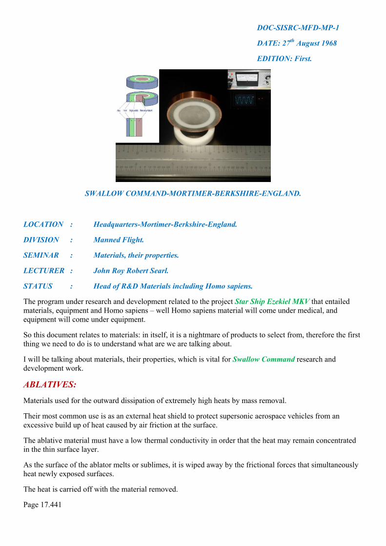
SWALLOW COMMAND-MORTIMER-BERKSHIRE-ENGLAND.
LOCATION : Headquarters-Mortimer-Berkshire-England.
DIVISION : Manned Flight.
SEMINAR : Materials, their properties.
LECTURER : John Roy Robert Searl.
STATUS : Head of R&D Materials including Homo sapiens.
The program under research and development related to the project Star Ship Ezekiel MKV that entailed materials, equipment and Homo sapiens – well Homo sapiens material will come under medical, and equipment will come under equipment.
So this document relates to materials: in itself, it is a nightmare of products to select from, therefore the first thing we need to do is to understand what are we are talking about.
I will be talking about materials, their properties, which is vital for Swallow Command research and development work.
ABLATIVES:
Materials used for the outward dissipation of extremely high heats by mass removal.
Their most common use is as an external heat shield to protect supersonic aerospace vehicles from an excessive build up of heat caused by air friction at the surface.
The ablative material must have a low thermal conductivity in order that the heat may remain concentrated in the thin surface layer.
As the surface of the ablator melts or sublimes, it is wiped away by the frictional forces that simultaneously heat newly exposed surfaces.
The heat is carried off with the material removed.
Page 17.441

The less material that is lost, the more efficient is the material.
The ablative material also should have a high thermal capacity in the solid, liquid, and gaseous states; a high heat of fusion and evaporation; and a high heat of dissociation of its vapors.
The ablative agent, or ablator, is usually a carbonaceous organic compound, such as a phenolic plastic.
That is why in press plus television news upon my work being Demo one, you see that I was using plastic for the shells, now you know why.
As the dissociation products are lost as liquid or vapor, the char is held in place by the refractory reinforcing fibers, still giving a measure of heat resistance.
The effective life of an ablative is short, calculated in seconds per millimeter of thickness for the distance traveled in the atmosphere.
Single ablative materials seldom have all of the desirable factors, and thus composites are used.
Phenolic or epoxy resins are reinforced with asbestos fabric, carbonized cloth, or refractory fibers, such as asbestos, fused silica, and glass.
The refractory fibers are incorporated for not only mechanical strength, but also have a function in the ablative process, and surface-active agents may be added to speed the rate of evaporation.
Ablative paint:
For protecting woodwork, may be organic silicones, which convert to silica at temperatures above 20000F – 10930C.
Metals can resist temperatures higher than their melting point by convection cooling or thermal cooling, which is heat protection by heat exchange with a coolant.
Thus, tungsten W 74 can be arc-melted in a copper Cu 29 kettle, which is cooled by circulating water.
The container metal must have high conductivity, and the heat must be quickly carried away and stored or dissipated.
When convection cooling is difficult or not possible, cooling may be accomplished by a heat sink.
I am quoting this information to let you see what options I had for this work and how did I select them.
Page 17.442

Heat sink cooling:
Depends on the heat absorption capability of the structural material itself or backed up by another material of higher heat absorption.
I am aware that copper Cu 29, beryllium Be 4, graphite, and beryllium oxide have been used.
A heat sink material should have high thermal conductivity, high specific gravity.
The use of carbon fibre in aircraft is growing steadily.
Shown here is a Martin Baker carbon fibre-reinforced composite ejection seat under test.
Man has advanced a long way since man first flew a heavier than aircraft machine, both in science and in technology, and has gone where no other animal has been.
His sensors may be lacking in respect to other animals, but makes up for it in brain capability.
Only problem with the Homo sapiens is their failures to accept their body structure as great, where all other animals do accept their bodies as nature created them without complaining.
Hello, you forgot your aircraft!
I, Prof. John Searl, head of research and development have to be responsible for the materials he selects for the studies being undertaken to generate a new concept in flight that can employ both air and space functions for the benefit of commercial transportation
I do try to encourage companies and organisations involved in advanced, high performance, structural composites throughout the world to come together to strengthen this rapidly growing, yet newly emerging, basic manufacturing industry.
At this seminar, I stressed that a new manufacturing industry such as this needs a developing and expanding market, not only for strategic defence reasons.
In addition, to develop further the applications of these materials in the widest possible range of engineering and industrial products, which the Searl Technology can advance with designs for land, road, rail, and air and space expansion, as a market business would indeed benefit this planet with increased employment of its labour force.
Searl International Space Research Consortium has specialised divisions, each has to employ materials within its research programs, and space exploration has the greatest demand on getting our sums right the first time, and as a research and development unit, I do not just fly aircraft but also creating the future ones yet to be,
Materials for me are vital issue, based upon that FACT; I need data from materials suppliers, and from a technical section, involving all sectors of industry plus research organisations, designers, and universities.
Then Searl International Space research Consortium can be said to truly represent the whole of the globe advanced composites industry that sure would be the day that technology base would create a better world.
Page 17.443

If the Government is really interested in encouraging new manufacturing industry then here is an ideal example for support where Searl International Space Research Consortium is genuine demonstrator programs of what it is undertaking in research and development which will yield substantial benefits in the future for the world as a whole and not just a small part thereof.
The Governments should commit itself to the emerging Searl Technologies and if this technology is not accepted the results will be increasing investments in pollution class products as usual.
No doubt in my mind that there will be an increase in investment in advanced materials but it will be abroad and by 1990s they will I expect an even larger quantity of imported advanced composite materials in the UK than the high figure noted currently, in the statistics covering carbon fibre products, for example:
Searl International Space Research Consortium underlined at its seminar that Britain is in danger of seeing the US, Japan, France and Germany establishing better component manufacturers and design facilities.
This will give them a lead in industrial and general engineering applications because their national commitment today to advanced composite materials for aerospace and defence products.
The Searl Technology is not, therefore, a mature business such as that covered by the British Plastics Federation, but one at the beginning of a product life cycle.
To my mind, there is a need for better fabrication methods are needed, as well as an increase in types and quality of composite materials, to meet the demands of Swallow Command, S.I.S.R.C. in general and NST Ltd.
Searl Technology Ltd and Searl Magnetic Ltd would also benefit from better materials for its broader base engineering research and development undertakings, which are in motion.
An understanding of ‘through’ and ‘life’ costs and parts consolidation needs to be acquired by Searl technology engineers and specifiers if these materials are to be effectively used by Swallow Command and its various units.
Unlike metals, composites lend themselves to complex integrated designs, providing a specific answer to my engineering problems, which are many.
Therefore, computer-aided design, laminate analysis and comparative performance data banks are essential for SWALLOW COMMAND engineers to make real progress with these materials.
Knowledge of fibre forms and polymer chemistry are also of the utmost importance.
These special features associated with a new industry underline the education and training requirements throughout Searl Technologies complex throughout the world if this company are to have a viable and competitive industry in the future.
There is a distinct shortage of skilled people in these fields and this problem must be addressed effectively and urgently.
Because of the engineering and design requirements, it seems especially appropriate for companies to be associated with Searl and his engineering and design teams.
I can only hope that this seminar document will serve to emphasise the opportunities for these structural materials that will be required by SWALLOW COMMAND in an ever-increasing range of applications.
The future looks bright so turn on the lights and be seen, to hide is not the solution to the future, but be seen creating, talking and demonstrating the future that shall be now; is the only solution available to secure that future, don’t leave for tomorrow what you can do today.
Have faith in all that you do, without faith is there is no hope for planet earth.
Page 17.444

This should help you to understand the class of materials, which I used in my work during 1963 to 1979.
So far within this book you have only seen the value of just one hair of a human head that has been involved within this study, from that statement you can guess this book will become the largest book ever to been written by one man for the general public to read.
It has been a great pleasure just to look back upon my life; and remember the hell I have gone through to get to old age.
It is good that we can freeze time frames, through which we can see what we have missed out on in life when we grow old and no one cares about you anymore.
Those girls who gave you the signal to come and get it, and you run the other way instead, how now you regret that event, that job that was offer and you refused it only to see too late what you have missed out on. Yes, the S.E.G falls in the same category, people have the offer but lose out because they allow greed to rule them.
Page 17.445

I will end this issue at this point as materials is a major requirement for research and development undertakings and for you to understand the problems which are involved will be the only way you will understand the world of reality is not all Gold.
This document released by the authority of:
Prof. John Roy Robert Searl Head of Research and Development.
Man flight division – human studies.
You may wonder what my life was like; from the marriage side unhappy, from my employment side I was very happy, every day was exciting, something new to learn, something new to do, often working two jobs a day to make ends meet.
Sad to state that I was glad to work 18 hours out of 24 hours, sometimes a whole 36 hours none stop I would work.
Strange really, you at an age where life should had been happy with a wife who care about you and children that loved you.
Unfortunate that was not to be the case, it would be other people’s children that would love me, not my own, my own would steal and lie to me, walk over me when I collapsed like if you were some dogs mess laying on the floor.
Today it is still other people’s children who are devoted to me, mine no longer exists, and they claim to people that I am dead and they buried and forgotten me, that I am a imposture pretending to be him; that is nothing new.
However, those days which have now gone for good, leave pictures of those valves etc that I worked with the excitement of blowing fuses and finding out why.
This is my world the world of reality, the world, which was full of excitement, creative, and a pleasure, sadly its now the world forgotten, like us old ones they say we have had our days and must be replaced.
So few every saw what I created, today no one really wants to know.
I represent yesterday and today, and the future, which is meant to be. May the future be just as great as the past was for me.
Page 17.446

This is my set up at 17 St. Stephens Close, Mortimer some of the equipment you have seen in TV newsreels, unfortunate I have no photos left from that time, but with a strike of luck the set up arrived here old but not too bad for its age.
It was a typical Aircraft Equipment which was better known as the T.1154/r.1155, yes it was that 1154 that brought the GPO detectives running here to destroy – but left it as they saw that it was vital for my work.
Page 17.447

Does any one out there have this set up still available?
I would love to have it or could you take a great picture of it in colour to show those bright colour knobs I cannot colour them on this picture but it would be nice to have real photos of that set up, just to remember 17 St. Stephens close in that time period of 1968.
There must been many airmen radio officers that actually use this set up, do any of you got photos of this setup, either with you in an aircraft, name type and call sign as a matter of interest of the past, or had such a set up in your shed.
The real details of that set up is as follows Marconi AD.87B/8882B a sending and receiving installation for general communication and direction finding which was critical for my work.
If so, please kindly send to me by e- mail either [email protected] which will be forwarded straight to me.
Bless you for your kind help in this request.
The valves shown on page 17.446: representative range of valve bases in current use, showing how they vary.
Where there is no locating key, the pins are asymmetrically arranged, of cause I can go on and on about this time, as I was so involved with my research creating control systems for the model discs and to top that the model railway layout to be fully automatic control which I term train control.
Repairing TV sets, Radio sets was great fun, to have been involved in the big switch over to a fix power system ready for Atomic power to come on line was great experience for me.
Looking back now, it is sad that I gave up jobs which I grew to love so much, because the contract I was book on was completed, so I moved on to look for new adventures to tackle and there were many to choose from.
Yet, there was a reason for that status to obtain hands on experience across the band of science and technology, which I had to know for the undertaking of this technology; without such hands on experience, I would be of little value if any at all for this technology.
Therefore, if fools want to insult me with stupidity on the internet, believing they are informing the world like idiots – most welcome to do so, it is a free world with my blessings.
My world was certainly different to that of today’s, the problem is that the world technically is moving so fast I do not have the funds to keep up with the changes in technology and science including medical, materials, components and equipment without doubt it is entirely different world to that of mine.
This world has changed indeed this is now my world somewhat different to my world that I knew.
Page 17.448

The world of reality that could be if we wanted it to be:
Page 17.449

This is the world of reality: I would like to see more of; to be loved and to give love – I close now with love to all my viewers – see you again soon.
Page 17.450