statys xs - socomec · statys xs - iomstaxs1217-en04 - socomec en 7 2.4. electrical risk risk of...
TRANSCRIPT

STATYS XS16A / 32A
EN
www.socomec.com
http://www.socomec.com/
OPERATING
AND
INSTALLATION
MANUAL

2 EN STATYS XS - IOMSTAXS1217-EN_04 - SOCOMEC
1. WARRANTY CERTIFICATE . . . . . . . . . . . . . . . . . . . . . . . . . . . . . . . . . . . . . . . . . . . . . . . .3
2. SAFETY INSTRUCTIONS . . . . . . . . . . . . . . . . . . . . . . . . . . . . . . . . . . . . . . . . . . . . . . . . . .4
2.1. Precautions . . . . . . . . . . . . . . . . . . . . . . . . . . . . . . . . . . . . . . . . . . . . . . . . . . .4
2.2. Security . . . . . . . . . . . . . . . . . . . . . . . . . . . . . . . . . . . . . . . . . . . . . . . . . . . . . .5
2.3. Warning plate symbols . . . . . . . . . . . . . . . . . . . . . . . . . . . . . . . . . . . . . . . . . . .6
2.4. Electrical risk . . . . . . . . . . . . . . . . . . . . . . . . . . . . . . . . . . . . . . . . . . . . . . . . . .7
2.5. Risk of power cut . . . . . . . . . . . . . . . . . . . . . . . . . . . . . . . . . . . . . . . . . . . . . . .7
3. PRODUCT DESCRIPTION . . . . . . . . . . . . . . . . . . . . . . . . . . . . . . . . . . . . . . . . . . . . . . . . .8
3.1. Statys XS Feature . . . . . . . . . . . . . . . . . . . . . . . . . . . . . . . . . . . . . . . . . . . . . . .8
3.2. Packaging . . . . . . . . . . . . . . . . . . . . . . . . . . . . . . . . . . . . . . . . . . . . . . . . . . . . .9
4. PRODUCT INTRODUCTION . . . . . . . . . . . . . . . . . . . . . . . . . . . . . . . . . . . . . . . . . . . . . . . 10
4.1. Front Panel . . . . . . . . . . . . . . . . . . . . . . . . . . . . . . . . . . . . . . . . . . . . . . . . . . . 10
4.2. LCD. . . . . . . . . . . . . . . . . . . . . . . . . . . . . . . . . . . . . . . . . . . . . . . . . . . . . . . . .11
4.3. Rear Panel . . . . . . . . . . . . . . . . . . . . . . . . . . . . . . . . . . . . . . . . . . . . . . . . . . .12
4.4. Interfaces . . . . . . . . . . . . . . . . . . . . . . . . . . . . . . . . . . . . . . . . . . . . . . . . . . . .13
5. INSTALLATION . . . . . . . . . . . . . . . . . . . . . . . . . . . . . . . . . . . . . . . . . . . . . . . . . . . . . . . . .14
5.1. Choose an installation location . . . . . . . . . . . . . . . . . . . . . . . . . . . . . . . . . . .14
5.2. Installation Procedure: . . . . . . . . . . . . . . . . . . . . . . . . . . . . . . . . . . . . . . . . . .14
5.3. Electrical power installation . . . . . . . . . . . . . . . . . . . . . . . . . . . . . . . . . . . . . .14
6. OPERATING . . . . . . . . . . . . . . . . . . . . . . . . . . . . . . . . . . . . . . . . . . . . . . . . . . . . . . . . . . .16
6.1. Boot up . . . . . . . . . . . . . . . . . . . . . . . . . . . . . . . . . . . . . . . . . . . . . . . . . . . . . .16
6.2. Switch input source . . . . . . . . . . . . . . . . . . . . . . . . . . . . . . . . . . . . . . . . . . . .16
6.3. Measurements . . . . . . . . . . . . . . . . . . . . . . . . . . . . . . . . . . . . . . . . . . . . . . . .16
6.4. Configuration . . . . . . . . . . . . . . . . . . . . . . . . . . . . . . . . . . . . . . . . . . . . . . . . .17
7. DRY CONTACTS AVAILABLE FOR CONFIGURATION . . . . . . . . . . . . . . . . . . . . . . . . . .17
9. SYSTEM SPECIFICATIONS . . . . . . . . . . . . . . . . . . . . . . . . . . . . . . . . . . . . . . . . . . . . . . .18
10. TROUBLESHOOTING . . . . . . . . . . . . . . . . . . . . . . . . . . . . . . . . . . . . . . . . . . . . . . . . . .19
EN CONTENTS

3ENSTATYS XS - IOMSTAXS1217-EN_04 - SOCOMEC
1. WARRANTY CERTIFICATE
The warranty terms are stipulated in the offer, by default the following clauses apply.
The SOCOMEC warranty is strictly limited to the product(s) and does not extend to equipment which may be
integrated with this(these) product(s), nor the performance of this equipment.
The manufacturer guarantees its material to be free from manufacturing faults and defects in design, material or
workmanship, subject to the limits set forth below.
The manufacturer reserves the right to modify the delivery with a view to fulfilling these guarantees or to replace
defective parts. The manufacturer's warranty does not apply in the following cases:
fault or defect in the design of parts added or supplied by the customer;
fault due to unforeseen circumstances or force majeure;
replacement or repair resulting from the normal wear of the modules or machinery;
damage caused by negligence, lack of proper maintenance or misuse of the products;
repair, modification, adjustment or replacement of parts performed by unqualified third parties or personnel without
the express agreement of SOCOMEC.
The warranty period is twelve months commencing from the date of delivery of the product.
The repair, replacement or modification of the parts during the warranty period does not extend the warranty
period.
In order to establish a valid warranty claim, the purchaser must notify the manufacturer in writing immediately after
the discovery of any defects which are attributed to the material and provide any and all supporting evidence of the
defects at the latest within eight days before the date of expiry of the warranty.
Defective parts which have been returned and replaced free of charge shall become the property of SOCOMEC.
The warranty is void if the purchaser has undertaken modifications or repairs on the devices on his or her own
initiative and without the express consent of the manufacturer.
The manufacturer's responsibility is strictly limited to the obligations defined in this warranty (repair and
replacement) excluding any other right to claim compensation or indemnity.
Any import tax, duty, fee or charge of any nature whatsoever imposed by European regulations or those of an
importing country or of a transit country shall be paid by the purchaser.
CORPORATE HQ CONTACT: SOCOMEC SAS, 1-4 RUE DE WESTHOUSE, 67235 BENFELD, France.

4 EN STATYS XS - IOMSTAXS1217-EN_04 - SOCOMEC
2. SAFETY INSTRUCTIONS
2.1. PrecautionsThis document provides essential instructions regarding safety, handling and connections for STATYS XS.
Carefully read this manual before operating STATYS.
Reference security information is in English language
Keep this manual in a safe place for future reference.
The manufacturer will not be held liable for failure to follow the instructions in this manual or available at www. socomec.com.
CAUTION
For optimal use, it is recommended to maintain the ambient temperature and humidity at the values specified by the manufacturer.
Do not expose STATYS to rain or any other type of liquid. Do not introduce foreign bodies into the unit.
WARNING
SOCOMEC maintains integral and exclusive ownership of its intellectual and industrial property rights regarding this document. Use of this document is limited to personal use by the recipient for the application specified by SOCOMEC. Any reproduction, modification or distribution of this document, whether in whole or in part, by any means whatsoever, is expressly prohibited without the prior written permission of SOCOMEC.
This document is not a specification. SOCOMEC reserves the right to modify the content of this document without notice.
Every component of this product is checked for high specification standards, this unit must be exclusively installed, commissioned and repaired by specialist technical personnel authorised by SOCOMEC.
The product which you have chosen taking into consideration its conditions of use, capacities and performance limits, is designed for commercial and industrial use only.
For use with so-called “critical applications”, the product may be required to comply with legal and regulatory obligations as well as specific local standards, and be adapted based on the recommendations of SOCOMEC. In all cases where the equipment is to be used for critical applications, you are advised to contact SOCOMEC in advance to confirm that the products are capable of meeting the required levels of safety, performance and reliability.
The term “critical applications” notably includes life support systems, medical applications, commercial transport, nuclear installations or any other system or application where the failure of the product is likely to cause substantial damage to persons or property.
All rights reserved
SOCOMEC disclaims any liability for damage to property or persons caused by errors that may have occurred in this document.

5ENSTATYS XS - IOMSTAXS1217-EN_04 - SOCOMEC
2.2. SecurityDo not install the product at the following locations without a qualified technician:
• Medical equipment directly related to human life preservation;
• Equipment on elevators or rapid transit systems related to personal safety;
• Critical computing hardware for public systems;
• Other equipment similar to the ones mentioned above.
Please discuss with your distributor before installing the product at the locations mentioned above. Special considerations and designs are required for the operation, setup, management, and maintenance of critical equipment and emergency backup power generators related to personal safety and public facilities.
Do not place vases or other water containers on top of the main unit. Water spilled into the machine may damage internal components and pose a shock hazard.
Using this product in locations with sparks, smoke, or natural gas may result in arcing, personal injury, and fire hazards.
The operating environment and storage method affects the product lifespan and malfunctions. Thus, please keep the product away from the following operating environments:
• Locations specified in the operating manual as high temperature, low temperature, and high humidity (temperatures outside -5 to 40° and relative humidity outside 5% to 90%);
• Locations with sparks;
• Locations with dust, corrosive material, salt content, or flammable gas;
• Outdoors.
Immediately stop using this product in the event of abnormal sounds or odors.
Contact your distributor for maintenance.
Improper grounding results in electrical leakage. Please make sure your AC input power is properly grounded.
Please confirm the input voltage does not exceed the rated capacity of the Statys XS.
Do not disassemble this product without a technician from the original manufacturer or authorized distributor. Doing so voids your warranty and is also a shock hazard.

6 EN STATYS XS - IOMSTAXS1217-EN_04 - SOCOMEC
2.3. Warning plate symbolsWe remind you of the need to observe the safety recommendations and warnings shown on the labels located inside and outside of the unit.
Danger ! High voltage (black/yellow)
Ground terminal
Read the user manual before performing any operation
7ENSTATYS XS - IOMSTAXS1217-EN_04 - SOCOMEC
2.4. Electrical risk
Risk of electric shock! Danger of property damage!
• Only qualified and authorized personnel are allowed to intervene on the product.
• Failure to follow the product instructions and this safety information may occur in personal injury, electric shock, burns or property damage.
• Before proceeding to the assembly(editing), maintains, cleaning, dismantling, in the connection or in the modifications, the product and the installation must be switched off otherwise you risk to be electrocuted. In addition, damage can occur in the installation and the product can be destroyed.
• The instructions are valid in conjunction with the specific instructions of the product.
• The products are designed exclusively for the application prescribed in the instructions. Only accessories authorized or prescribed by SOCOMEC may be used in combination with the devices.
• For any questions regarding the disposal of the product, contact SOCOMEC
• SOCOMEC disclaims any liability for damage caused to property or persons caused by errors that may have occurred in this document.
WARNING
All operations and maintenance must be performed by authorised personnel who have undertaken suitable training.
Scrupulously follow the operating or maintenance instructions described in this manual.
Take maximum precautions and determine which parts are live:
• by following the load diagrams,
• by checking the presence of power with a voltmeter, for example.
In normal operating conditions, there is no danger for personnel handling this equipment.
2.5. Risk of power cut
WARNING
Scrupulously follow the operating instructions described in this manual to prevent inadvertent power cuts which may pose a safety hazard to the user.
DANGER
Taking into account the presence of high leakage currents, it is essential to connect the ground cable before connecting the upstream and load sources.
Hazardous voltage may be present within STATYS after it is switched off.
In fact, the power supply voltage remains present at the input of each static contactor

8 EN STATYS XS - IOMSTAXS1217-EN_04 - SOCOMEC
3. PRODUCT DESCRIPTION
3.1. Statys XS FeatureThe Statys XS (Automatic Transfer System) features two independent power supply circuits supplying power to the load (as shown in Figure 1 below). In the event of a power failure in the main circuit, the Statys XS automatically switches to the other circuit to supply power to the load. The Statys XS automatically switches back to the main circuit after power is restored. In addition, the Statys XS also provides user configurable power states (voltage or frequency) for the Statys XS switching condition.
Source A
Source B
Load
L1STATYS XS
N1
L
NL2
N2
Source A
Source B
Load
L1STATYS XS
N1
L
NL2
N2
Load on Source A
Load on Source B

9ENSTATYS XS - IOMSTAXS1217-EN_04 - SOCOMEC
3.2. Packaging
• Remove the PE foam.
• Inspect accessories:
– RS-232 cable x1 pcs
– USB cable x1 pcs
– Quick Start guide
– Handle and screws x1 set
– Backplate and screws x1 set
– IEC C19 - C20 cables x2 (XS 16A only)
– Protective cover and screws x1 sed (XS 32A only)

10 EN STATYS XS - IOMSTAXS1217-EN_04 - SOCOMEC
4. PRODUCT INTRODUCTION
4.1. Front Panel
No. Item Description/function
Mute button Turns the sound of the alarm off when present
Source selection button Select source to view info: Input A, Input B, or Load
Info selection buttonSelect source info to view: voltage, frequency, current*, load capacity*
Input selection button Switch input source: Input A <-> Input B
LCD System status display
Error indicator Lit: System malfunction or abnormal Dim: System normal
Input indicator BLit: Normal input voltage and frequencyDim: Abnormal input voltage and frequencyFlashing: Indicates higher priority
Input indicator ALit: Normal input voltage and frequencyDim: Abnormal input voltage and frequencyFlashing: Indicates higher priority
USB port Connection for software setup or monitoring software
RS-232 port Connection for software setup or monitoring software
Dry contact port Dry Contact
External communication slot For external communication cards, e.g. RS- 485, SNMP
*only on the Output
1
1
2
2
3
3
4
4
5
5
6
6
7
7
8
8
9
9
10
10
11
11
12
12

11ENSTATYS XS - IOMSTAXS1217-EN_04 - SOCOMEC
4.2. LCD
A B
A
B
L
V
A
Hz
%
Symbol Description/function
Input A error or power failure
Input B error or power failure
Overload
System malfunction or abnormal
Alarm on
Alarm off
Digital display showing input/output power connected to load
Statys XS numeric display
A
B
12 EN STATYS XS - IOMSTAXS1217-EN_04 - SOCOMEC
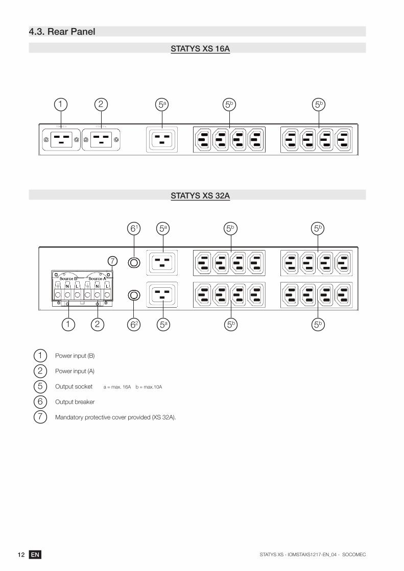
4.3. Rear Panel
STATYS XS 16A
STATYS XS 32A
1
1
1
5
2
2
2
6
7
5a
5a61
5a62
5b
5b
5b
5b
5b
5b
Power input (B)
Power input (A)
Output socket a = max. 16A b = max.10A
Output breaker
Mandatory protective cover provided (XS 32A).
7

13ENSTATYS XS - IOMSTAXS1217-EN_04 - SOCOMEC
4.4. Interfaces
• The Statys XS provides three standard communication ports: RS-232, USB, and 5 dry contacts.
RS-232
DRY CONTACT
The Statys XS provides five user configurable dry contacts for customized features. The capacity of each contact is 24Vdc / 1A, additional information is provided in § 7.
USB
Pin Definition Type Signal
1 N/A N/A N/A
2 TX Output TX
3 RX Input RX
4 N/A N/A N/A
5 GND Power source N/A
6 +12V Power source N/A
7 N/A N/A N/A
8 N/A N/A N/A
9 N/A N/A N/A
Pin Definition Signal
1 Common 3 N/A
2 Relay 3 Source A abnormal
3 Relay 4 Source B abnormal
4 Common 4 N/A
5 Relay 5 General alarm
6 Common 1 N/A
7 Relay 1 Pre-alarm active
8 Common 2 N/A
9 Relay 2 Over temperature
Pin Signal
1 VBUS
2 D-
3 D+
4 GND
• The Statys XS provides one external communication slot (optional) for the user: SNMP or RS-485 (see § 4.3.1)

14 EN STATYS XS - IOMSTAXS1217-EN_04 - SOCOMEC
5. INSTALLATION
5.1. Choose an installation locationAn appropriate installation location will optimize system performance, reducethe chances of malfunctions, and prolong product lifespan. Please follow theguidelines below for an appropriate location:
• Avoid excessive high temperature or high humidity;
• Keep away from dust, volatile gases, excessive salt content, or corrosive gases;
• Do not use outdoors.To avoid over temperature because of heat accumulation, please ensure the product is installed in a ventilated area.
5.2. Installation Procedure:
1. Open package and note the packaging layers. Keep the box and packaging material in case further
transportation is required.
2. Check for damage to the Statys XS from shipping and handling. Please contact your local distributor if the
product is damaged.
3. Check the input power cable/socket and output socket of the delivered Statys XS model with your order.
4. Affix the backplate (Figure 1) onto the Statys XS (Figure 2). Affix the Statys XS onto the frame of the chassis
(Figure 3).
5. Insert the load plugs into the Statys XS sockets labelled "OUTPUT" and spreading them as evenly as possible.
6. Check that the total load does not exceed Statys XS specifications (e.g. voltage, current).
7. Supply power to the Statys XS. The Statys XS automatically boots up after 1 second and supplies the capacity
power to the connected load.
5.3. Electrical power installation
External upstream protection :
The circuit breaker ratings bellow are recomended values. These protective devices still need to be selected and
configured taking into account the installation and the diameter of cable used.
Circuit breaker rating A:
• 16A STATYS XS : 16A circuit breaker ; tripping curve D
• 32A STATYS XS : 32A circuit breaker ; tripping curve D

15ENSTATYS XS - IOMSTAXS1217-EN_04 - SOCOMEC
Figure 3
Figure 1
Figure 2
16 EN STATYS XS - IOMSTAXS1217-EN_04 - SOCOMEC
6. OPERATING
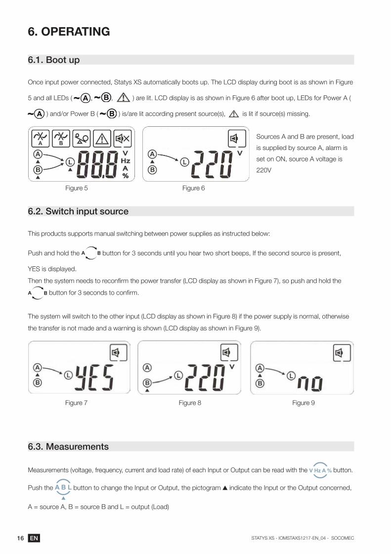
6.1. Boot up
Once input power connected, Statys XS automatically boots up. The LCD display during boot is as shown in Figure
5 and all LEDs ( , , ) are lit. LCD display is as shown in Figure 6 after boot up, LEDs for Power A (
) and/or Power B ( ) is/are lit according present source(s), is lit if source(s) missing.
6.2. Switch input source
This products supports manual switching between power supplies as instructed below:
Push and hold the button for 3 seconds until you hear two short beeps, If the second source is present,
YES is displayed.
Then the system needs to reconfirm the power transfer (LCD display as shown in Figure 7), so push and hold the
button for 3 seconds to confirm.
The system will switch to the other input (LCD display as shown in Figure 8) if the power supply is normal, otherwise
the transfer is not made and a warning is shown (LCD display as shown in Figure 9).
6.3. Measurements
Measurements (voltage, frequency, current and load rate) of each Input or Output can be read with the button.
Push the button to change the Input or Output, the pictogram indicate the Input or the Output concerned,
A = source A, B = source B and L = output (Load)
Figure 5 Figure 6
Figure 7 Figure 8 Figure 9
Sources A and B are present, load
is supplied by source A, alarm is
set on ON, source A voltage is
220V

17ENSTATYS XS - IOMSTAXS1217-EN_04 - SOCOMEC
6.4. ConfigurationStatys XS can be customised via USB or serial link using a dedicated software named XS Config.
Please refer to the download section of www.socomec.com.
7. DRY CONTACTS AVAILABLE FOR CONFIGURATION
Event Code
1 Source A voltage abnormal Er03
2 Source B voltage abnormal Er04
3 Source A frequency abnormal Er05
4 Source B frequency abnormal Er06
5 Output Over Load Er16
6 Unit fault (Source A circuit power defected) Er22
7 Unit fault (Source B circuit power defected) Er23
8 Cabinet temperature abnormal Er24
9 Unit fault (Sensor circuit defect) Er25
10 Unit fault (EEPROM data abnormal) Er26
11 LCD panel connection abnormal Er28
12 Overload time out Er30
13 Transferring fail by sync setting condition Er31
14 Pre-alarm active Er32
15 Communication connection abnormal Er33
16 General alarm

18 EN STATYS XS - IOMSTAXS1217-EN_04 - SOCOMEC
9. SYSTEM SPECIFICATIONS
Model STAYS XS 16A STAYS XS 32A
Input
Input voltage 200/208/220/230/240V230V factory setting +/-10% (configurable +/-5% to +/-20%)
Input voltage range 180Vac - 264Vac
Input frequency 50 / 60Hz+/-10% (configurable +/-5% to +/-20%)
Output
Output voltage Equal to Input
Rated Output current16A 32A
Can be configured to lower current for alarm management
Protection Electronic circuit and upstream protections
Transfer time(ms) ITIC curve compliant
Admitted overload 125% / 1 minutes, 150% / 30 seconds
Connection
Input IEC C20 x 2 50A terminal 1 x 6P 10mm²
output1 x IEC C19 (max. 16A)8 x IEC C13 (max. 10A)
2 x IEC C19 (max. 16A)16 x IEC C13 (max. 10A)
Communication 5 Dry contacts
Communication (option card) SNMP o r RS-485
Port for system access RS 232 / USB
Display LCD+LED
Physical
Dimension W x D x H (mm) 440 x 285 x 44 440 x 360 x 88
Net Weight (kgs) 4 6
Environment
Working temperature -5 to 40°C @ 5 to 90% RH (non-condensing)
Standards compliance
Safety EN 60950-1
EMC EN 62310-2
19ENSTATYS XS - IOMSTAXS1217-EN_04 - SOCOMEC
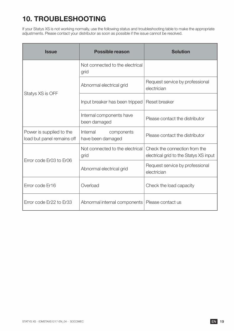
10. TROUBLESHOOTINGIf your Statys XS is not working normally, use the following status and troubleshooting table to make the appropriate adjustments. Please contact your distributor as soon as possible if the issue cannot be resolved.
Issue Possible reason Solution
Statys XS is OFF
Not connected to the electrical grid
Abnormal electrical gridRequest service by professional electrician
Input breaker has been tripped Reset breaker
Internal components have been damaged
Please contact the distributor
Power is supplied to the load but panel remains off
Internal components have been damaged
Please contact the distributor
Error code Er03 to Er06
Not connected to the electrical grid
Check the connection from the electrical grid to the Statys XS input
Abnormal electrical gridRequest service by professional electrician
Error code Er16 Overload Check the load capacity
Error code Er22 to Er33 Abnormal internal components Please contact us

Non contractual document. Subject to change without notice.
Socomec: our innovations supporting your energy performance
The specialist for critical applications
Your power management expert
10 % of sales revenue dedicated to R&D
•Energy quality•Energy availability•Energy storage
400 experts dedicated to service provision
• Prevention and repairs•Measurement and analysis•Optimisation• Consultancy, commissioning
and training
1 independent manufacturer
• Control, command of LV facilities
•Safety of persons and assets
3,200 employees worldwide
• Measurement of electrical parameters
•Energy management
A worldwide presence
80 countries where our brand is distributed
8 production sites•France (x3)•Italy•Tunisia•India•China (x2)
27 subsidiaries•Australia•Belgium•China•France•Germany•India•Italy•Netherlands•Poland•Romania•Singapore •Slovenia•Spain•Switzerland•Thailand•Tunisia•Turkey•UK•USA
POWER sWitCHing
POWER mOnitORing
POWER COnvERsiOn
ExPERt sERviCEs
HEAD OFFICE
SOCOMEC GROUPSAS SOCOMEC capital 10 633 100 €R.C.S. Strasbourg B 548 500 149 B.P. 60010 - 1, rue de Westhouse F-67235 Benfeld CedexTel. +33 3 88 57 41 41 - Fax -33 3 88 57 78 [email protected]
YOUR DISTRIBUTOR / PARTnER
www.socomec.com
Noncontractualdocum
ent.©2018,Socom
ecSAS.Allrightsreserved.-Docum
entprintedonpaperfrom
sustainablymanagedforests.