status of the ilc main linac bpm r&d
DESCRIPTION
Status of the ILC Main Linac BPM R&D. Thibaut Lefevre CERN Claire Simon CEA Sacley Sebastien Vilalte LAPP Manfred Wendt Fermilab. Agenda. Introduction CM-”free” cavity BPMs. The SLAC prototype BPM. Cold ILC cavity BPM R&D at Fermilab, Read-out hardware developments. - PowerPoint PPT PresentationTRANSCRIPT
Status of the ILC Main Linac BPM R&D
Thibaut LefevreCERN
Claire SimonCEA Sacley
Sebastien VilalteLAPP
Manfred WendtFermilab
11/19/2008 1ILC08 Main Linac WG
Agenda
• Introduction• CM-”free” cavity BPMs.
The SLAC prototype BPM. • Cold ILC cavity BPM R&D at Fermilab,
Read-out hardware developments.• Re-entrant BPM R&D for XFEL & CTF3
at CEA-Saclay.• Radiation tolerant read-out electronics R&D
for CTF3 at LAPP.• Conclusions
11/19/2008 ILC08 Main Linac WG 2
Cold BPM for an ILC Cryomodule
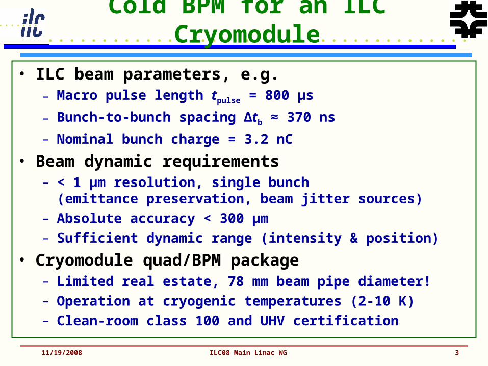
• ILC beam parameters, e.g.– Macro pulse length tpulse = 800 µs
– Bunch-to-bunch spacing Δtb ≈ 370 ns
– Nominal bunch charge = 3.2 nC
• Beam dynamic requirements– < 1 µm resolution, single bunch
(emittance preservation, beam jitter sources)– Absolute accuracy < 300 µm– Sufficient dynamic range (intensity & position)
• Cryomodule quad/BPM package– Limited real estate, 78 mm beam pipe diameter!– Operation at cryogenic temperatures (2-10 K)– Clean-room class 100 and UHV certification
11/19/2008 ILC08 Main Linac WG 3
Cavity BPM Principle
11/19/2008 ILC08 Main Linac WG 4
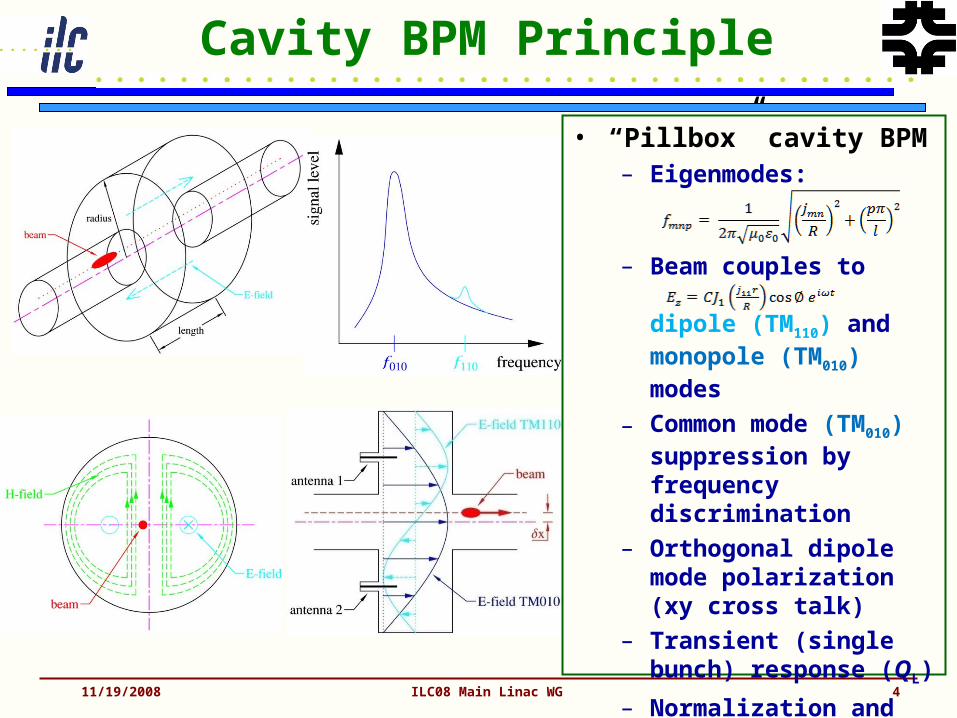
• “Pillbox” cavity BPM– Eigenmodes:
– Beam couples to
dipole (TM110) and monopole (TM010) modes
– Common mode (TM010) suppression by frequency discrimination
– Orthogonal dipole mode polarization (xy cross talk)
– Transient (single bunch) response (QL)
– Normalization and phase reference
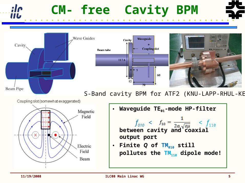
CM-”free” Cavity BPM
• Waveguide TE01-mode HP-filter
between cavity and coaxial output port
• Finite Q of TM010 still pollutes the TM110 dipole mode!
11/19/2008 ILC08 Main Linac WG 5
< f110f010 <
S-Band cavity BPM for ATF2 (KNU-LAPP-RHUL-KEK)
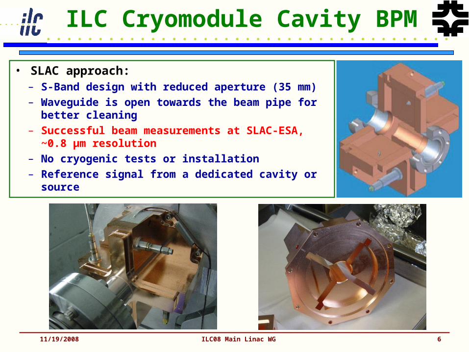
ILC Cryomodule Cavity BPM
• SLAC approach:– S-Band design with reduced aperture (35 mm)
– Waveguide is open towards the beam pipe for better cleaning
– Successful beam measurements at SLAC-ESA, ~0.8 µm resolution
– No cryogenic tests or installation
– Reference signal from a dedicated cavity or source
11/19/2008 ILC08 Main Linac WG 6
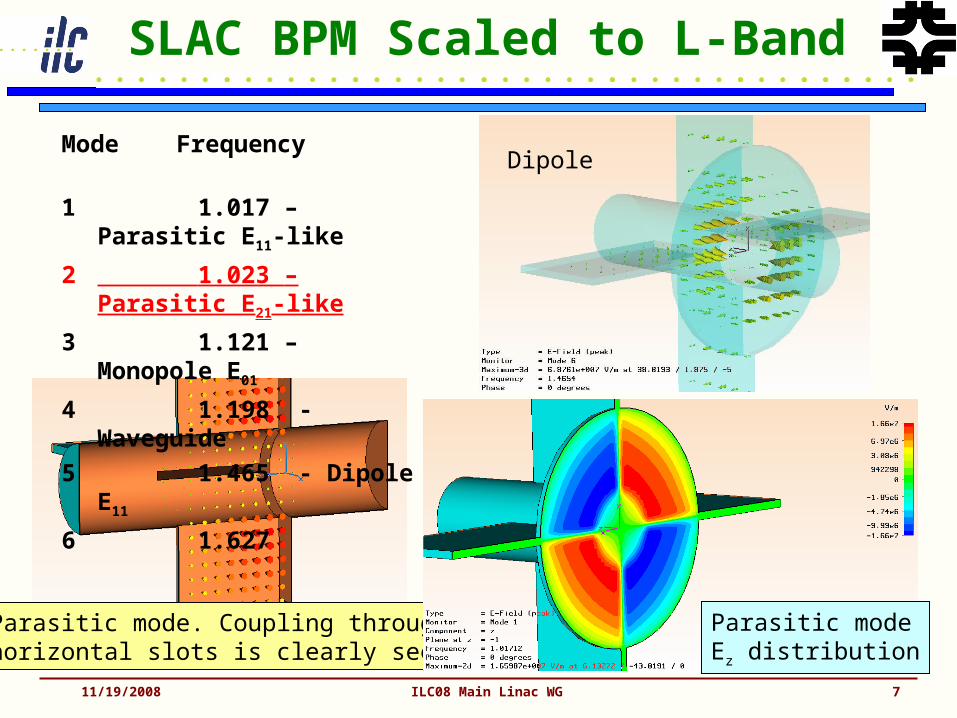
SLAC BPM Scaled to L-Band
11/19/2008 ILC08 Main Linac WG 7
Dipole
Parasitic mode. Coupling throughhorizontal slots is clearly seen
Parasitic modeEz distribution
Mode Frequency
1 1.017 – Parasitic E11-like
2 1.023 – Parasitic E21-like
3 1.121 – Monopole E01
4 1.198 - Waveguide
5 1.465 - Dipole E11
6 1.627
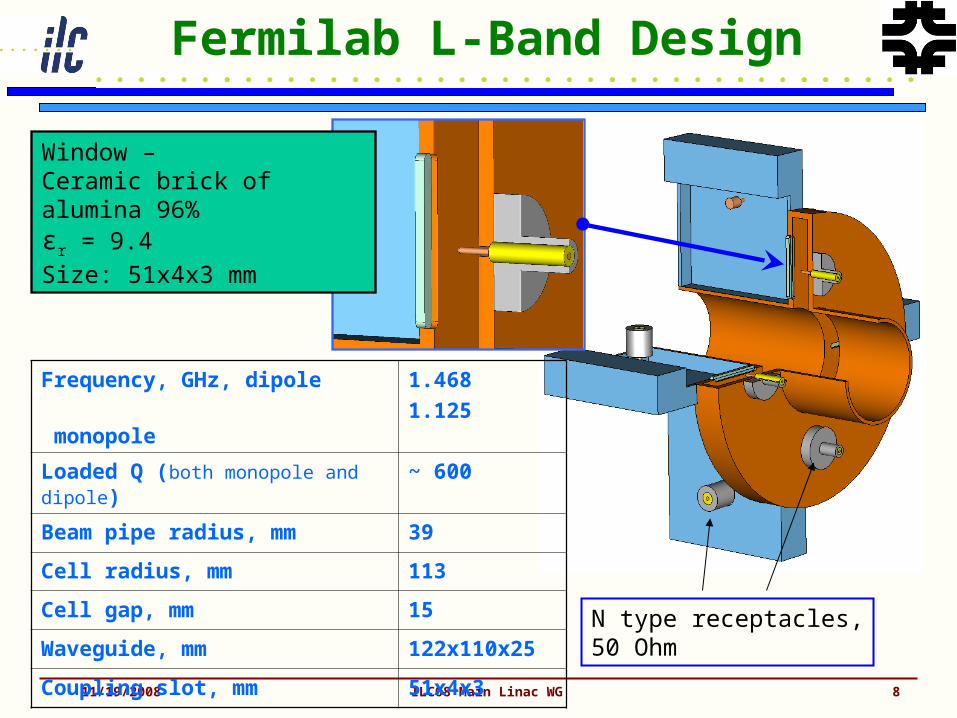
Fermilab L-Band Design
11/19/2008 ILC08 Main Linac WG 8
Frequency, GHz, dipole
monopole
1.468
1.125
Loaded Q (both monopole and dipole) ~ 600
Beam pipe radius, mm 39
Cell radius, mm 113
Cell gap, mm 15
Waveguide, mm 122x110x25
Coupling slot, mm 51x4x3
Window –Ceramic brick of alumina 96%εr = 9.4
Size: 51x4x3 mm
N type receptacles,50 Ohm
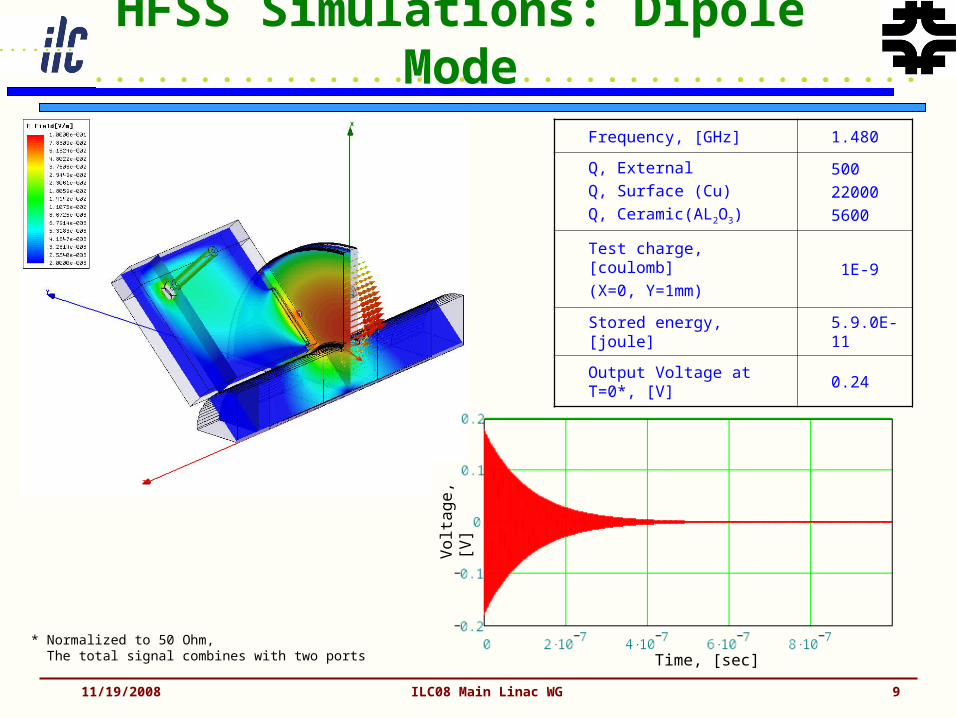
HFSS Simulations: Dipole Mode
11/19/2008 ILC08 Main Linac WG 9
Frequency, [GHz] 1.480
Q, ExternalQ, Surface (Cu)Q, Ceramic(AL2O3)
500220005600
Test charge, [coulomb](X=0, Y=1mm)
1E-9
Stored energy, [joule]5.9.0E-11
Output Voltage at T=0*, [V]
0.24
Volt
age,
[V]
Time, [sec]* Normalized to 50 Ohm, The total signal combines with two ports
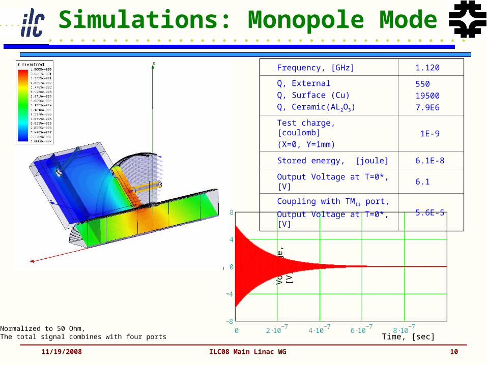
Simulations: Monopole Mode
11/19/2008 ILC08 Main Linac WG 10
Volt
age,
[V]
Time, [sec]* Normalized to 50 Ohm, The total signal combines with four ports
Frequency, [GHz] 1.120
Q, ExternalQ, Surface (Cu)Q, Ceramic(AL2O3)
550195007.9E6
Test charge, [coulomb](X=0, Y=1mm)
1E-9
Stored energy, [joule] 6.1E-8
Output Voltage at T=0*, [V] 6.1
Coupling with TM11 port,
Output Voltage at T=0*, [V]5.6E-5

Cold L-Band ILC BPM R&D
• Status:– EM simulations & construction finalized
– Brazing and low temperature UHV tests
– All parts manufactured, ready for brazing
– Prototype has “warm” dimensions
11/19/2008 ILC08 Main Linac WG 11

Cold ILC L-Band Cavity BPM
11/19/2008 ILC08 Main Linac WG 12
FNAL ILC Cavity BPM Summary
• Cold L-Band cavity BPM, fits in an ILC cryostat, 78 mm aperture.• Waveguide-loaded pillbox with slot coupling.• Dimensioning for f010 and f110 symmetric to fRF,
fRF = 1.3 GHz, f010 = 1.125 GHz, f110 = 1.468 GHz.• (Rsh/Q)110 ≈ 14 Ω (1 mm beam displ.), providing < 1 µm resolution.• Dipole- and monopole ports, no reference cavity for intensity
signal normalization and signal phase (sign).• Qload ≈ 600 (~10 % cross-talk at 300 ns bunch-to-bunch spacing).• Minimization of the X-Y cross-talk (dimple tuning).• Simple (cleanable) mechanics.• Many EM-simulations (HFFS, MWS) analyzing dimensions and
tolerances (see A. Lunin, et.al, DIPAC 2007).• Successful tests of the ceramic slot windows,
i.e. several thermal cycles 300 K -> 77 K -> 300 K• Next Steps:
– Warm prototype finalization (brazing), RF measurements, tuning, beam tests (at the A0-Photoinjector).
11/19/2008 ILC08 Main Linac WG 13
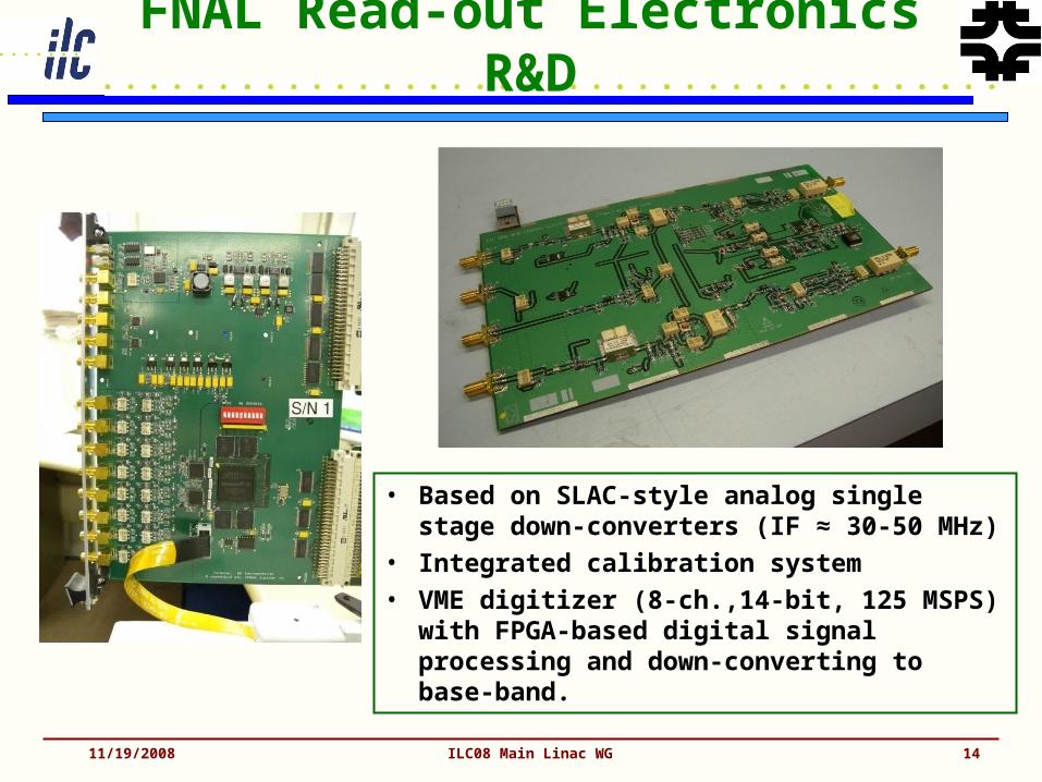
FNAL Read-out Electronics R&D
• Based on SLAC-style analog single stage down-converters (IF ≈ 30-50 MHz)
• Integrated calibration system
• VME digitizer (8-ch.,14-bit, 125 MSPS) with FPGA-based digital signal processing and down-converting to base-band.
11/19/2008 ILC08 Main Linac WG 14

15ILC/LCWS
XFELX-Ray Free-Electron LaserReentrant Cavity BPM for the XFEL (1)
Twelve holes of 5 mm diameter drilled at the end of the re-entrant part for a more effective cleaning (Tests performed at DESY).
Cu-Be RF contacts welded in the inner cylinder of the cavity to ensure electrical conduction.
Cryogenics tests at 4 K on feedthroughs is OK
• For the XFEL, mechanical design improved to respect tolerances of the BPM : Roll Angle 3 mrad, Transverse displacement 0.2 mm
• 30 reentrant cavity BPM will be installed in XFEL cryomodules
Copper coating (depth: 12 µm) to reduce losses. Heat treatment at 400°C to test: OK
Eigen modes
F (MHz) Ql (R/Q)l (Ω) at 5 mm
(R/Q)l (Ω) at 10 mm
Measured Measured Calculated Calculated
Monopole mode
1255 23.8 12.9 12.9
Dipole mode
1724 59 0.27 1.15
16ILC/LCWS
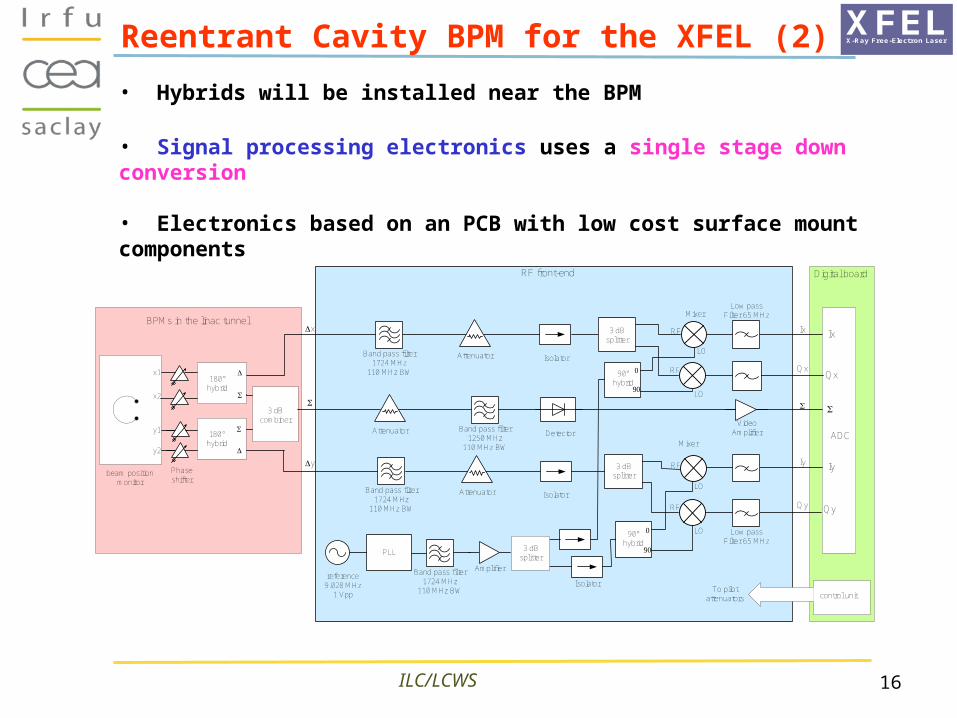
BPMs in the linac tunnel
beam positionmonitor
x1
x2
y2
y1
180°hybrid
3 dBcombiner
x
y
Qx
ADC
Digital board
Ix
Qx
Iy
Qy
180°
hybrid
Ix
Qy
Iy
Low passFilter 65 MHz
Low passFilter 65 MHz
Band pass filter1724 MHz
110 MHz BW
PLL
reference9.028 MHz
1 Vpp
RF front-end
Attenuator Band pass filter1250 MHz
110 MHz BW
Band pass filter1724 MHz
110 MHz BW
Amplifier
Isolator
Isolator
Detector
Isolator
Band pass filter1724 MHz
110 MHz BW
LO
RF
LO
RF
90°hybrid
LO
RF
LO
RF
90°hybrid
Mixer
Mixer
3 dBsplitter
3 dBsplitter
3 dBsplitter
Phaseshifter
VideoAmplifier
Attenuator
Attenuator
control unitTo pilot
attenuators
Reentrant Cavity BPM for the XFEL (2)
• Hybrids will be installed near the BPM
• Signal processing electronics uses a single stage down conversion
• Electronics based on an PCB with low cost surface mount components
XFELX-Ray Free-Electron Laser
17ILC/LCWS
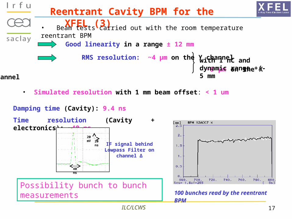
RMS resolution: ~4 µm on the Y channel
~8 µm on the X channel
XFELX-Ray Free-Electron LaserReentrant Cavity BPM for the XFEL (3)
Good linearity in a range ± 12 mm
with 1 nC and dynamic range +/- 5 mm
Possibility bunch to bunch measurements 100 bunches read by the reentrant BPM
Damping time (Cavity): 9.4 ns
Time resolution (Cavity + electronics): ~40 ns
• Beam tests carried out with the room temperature reentrant BPM
• Simulated resolution with 1 mm beam offset: < 1 um
20 ns
20 mV
40 ns
IF signal behind Lowpass Filter on
channel Δ

18ILC/LCWS
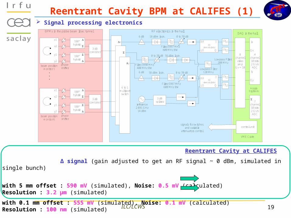
Reentrant Cavity BPM at CALIFES (1)
Bent coaxial cylinder designed to have:
- a large frequency separation between monopole and dipole modes
- a low loop exposure to the electric fields
• Cavity BPM is designed for the CTF3 probe beam (CALIFES)
• It is operated in single and multi-bunches modes
Eigen modes F (MHz) Ql (R/Q)l (Ω) at 5 mm
(R/Q)l (Ω) at 10 mm
Measured Measured Calculated Calculated
Monopole mode
3988 29.76 22.3 22.3
Dipole mode 5983 50.21 1.1 7
19ILC/LCWS
Signal processing electronicsBPMs in the probe beam linac tunnel
beam positionmonitor 1
x1
x2
y2
y1
180°hybrid
180°
hybrid
phaseshifter
3 dBcombiner
beam positionmonitor 6
x1
x2
y2
y1
180°hybrid
180°
hybrid
3 dBcombiner
.
.
.
6 to 1multiportswitch
phaseshifter
x
y
6 dB
6 dB
18 dBm leak.
18 dBm leak.
Filter 5997 MHz600 MHz BW
0 to 70 dB
0 to 70 dB
18 dBm leak.
Lowpass Filter120 MHz
0 to 70 dB
3 dBsplitter
reference2.891 GHz
14 dBm
RF electronics in the hall
8channel
videoamp
Gv = 10
4channel10 bits2 Gs/sADC
2channel10 bits2 Gs/sADC
DAQ in the hall
control unit
VME Crate
signals for switchesand variable
attenuators control
Ix
Qx
Iy
Qy
Filter 5997 MHz600 MHz BW
RF
LO
II-Q
demodulator
Q
RF
LO
II-Q
demodulator
Q
Lowpass Filter200 MHz
Filter 3990 MHz400 MHz BW
AcqirisDigitizers
Reentrant Cavity at CALIFES
Δ signal (gain adjusted to get an RF signal ~ 0 dBm, simulated in single bunch)
with 5 mm offset : 590 mV (simulated), Noise: 0.5 mV (calculated) Resolution : 3.2 µm (simulated)
with 0.1 mm offset : 555 mV (simulated), Noise: 0.1 mV (calculated) Resolution : 100 nm (simulated)
Reentrant Cavity BPM at CALIFES (1)
2015/10/08 CLIC08 Workshop
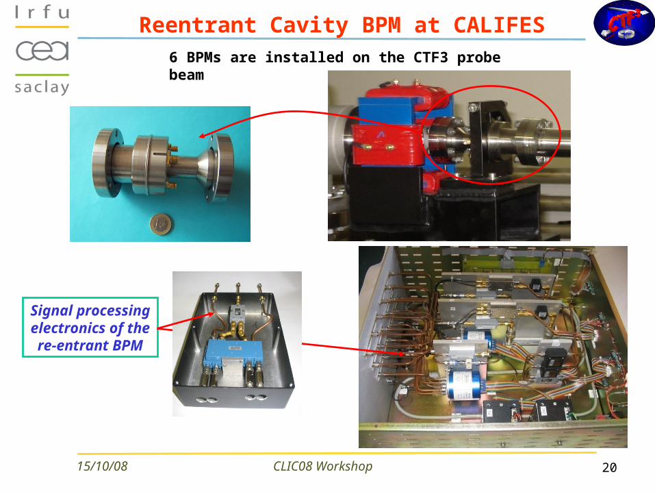
Reentrant Cavity BPM at CALIFES6 BPMs are installed on the CTF3 probe beam
Signal processing
electronics of the re-entrant BPM

11/19/2008 ILC08 Main Linac WG 21
BPM Acquisition architecture
Analog module: Intensity & deviations processing BPI or BPM.
DFE board: - digitalization 3channels, 12 bits / 200MSps. - Feed-back for analog modules: gains, calibration and attenuations.
- Daisy chain acquisition: 1 network cable per crate.
Acquisition PC : FESA-OASIS soft and specialist requirements feed-back.
→ Cost divided by a factor 3 comparing to a « far » acquisition.
4
Δ1
Σ
Δ2
DFEAnalog module
Acquisition PC >100m :SPECS+Gateway
Accelerator area <10m
ADC
network
Aim: reduction of costs of long analog cables/ADC → Rad-hard acquisition electronics close to beam.
11/19/2008 ILC08 Main Linac WG 22
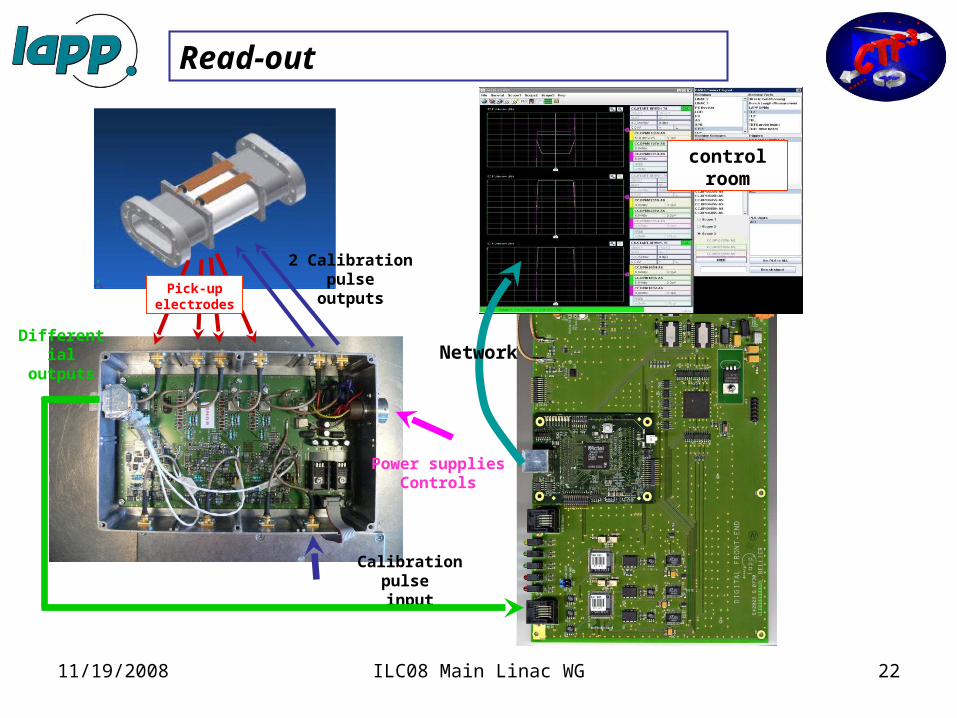
Read-out
Calibration pulse input
Power suppliesControls
2 Calibration pulse
outputs
Differential outputs
Pick-up electrodes
Network
control room

11/19/2008 ILC08 Main Linac WG 23
8 crates in TL2-CLEX
Uranus
11/19/2008 ILC08 Main Linac WG 24
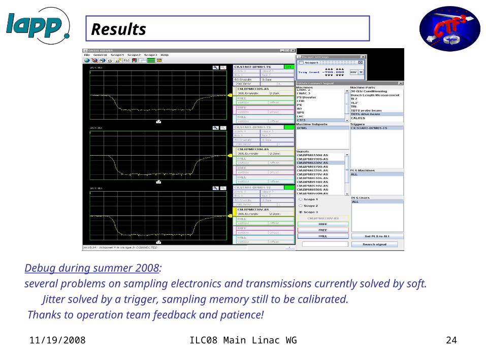
Results
Debug during summer 2008:
several problems on sampling electronics and transmissions currently solved by soft.
Jitter solved by a trigger, sampling memory still to be calibrated.
Thanks to operation team feedback and patience!
11/19/2008 ILC08 Main Linac WG 25
Future : acquisition for CLIC
The logical evolution of this system is to be dedicated to a larger accelerator as CLIC:
Rare acces from surface, high number of channels, rad-hard,
low-cost, low consumption…
Most important points to develop: elimination of cables
– Power supplies: autonomous (220V sector, DC-DC converters…).– Local calibration.– Network : flexible data collection, repetition crates… – Acquisition architecture: faster ADC, direct bpm read-out, continuous
sampling…– FPGA processing: raw data, processed data…– Radiations.
11/19/2008 ILC08 Main Linac WG 26
Future : acquisition for CLIC
→ All-around accelerator standard acquisition.
A lot of specifications to be discussed with the collaboration:
- Input stages and input dynamic ranges.
- Informations to collect: definition of transfer rates.
→ possible switching between FPGA local process of position/intensity
and raw data for precision.
- Definition of a standard crate for a module (n channels)
- Infrastructure possibilities to study (see Lars concrete shielded crate…)
- ETC…
11/19/2008 ILC08 Main Linac WG 27
Future : R&D in LAPP
LAPP decided to get involved for a 2 years development:
~3 men/year and IN2P3 funding ~50k€/year.
New acquisition board:
- 4 analog inputs with several input dynamic ranges, continuous 500Msps-12bits sampling.
- 6GHz optical link for data, timing: no more cables, no EMC problems…
- A Clock-management architecture to get free from timing problems.
Board for local power supplies/calibrations facility:
study of a 220V sector power supplied crate & local calibration.
→ Problem of radiations!

Conclusions
• Most R&D activates in the US were “on hold”.– Now restarted, on a lower budget, and a modified goal
(NML test facility, Project X)
• At Fermilab a cold L-Band cavity BPM prototype with 78 mm aperture, Qload ≈ 600, is in its final fabrication (brazing) procedure.
• A re-entrant BPM was tested at FLASH, achieving ~5 µm resolution (CEA-Saclay).
• Radiation tolerant read-out electronics are developed at European and US laboratories.
11/19/2008 ILC08 Main Linac WG 28