status of juno central detector and its prototyping - taup … · 2015-09-08 · status of juno...
TRANSCRIPT
Status of JUNO Central Detector and its prototyping
Zhimin Wang (IHEP, Beijing)
On behalf of JUNO collaboration
Neutrino, 8 September 2015, TAUP15, Torino, Italy

2
Outline • Central Detector • Physics features • Schedule • Prototyping

JUNO detector
A multi-purpose neutrino observatory
– Rock overburden: ~720m
– Largest LS detector: ~20kt@Φ35.4m
– Energy resolution: <3%@1MeV
– >1000p.e./MeV with high QE 20” PMTs coverage
– 1GHz sampling Waveform readout electronics
– <1kHz trigger rate @threshold <0.7MeV
3
Top muon veto Scintillator panels
Outer water tank Muon Cherenkov
veto
Steel structure
Vessel diameter: 35.4m
Liquid scintillator 20 kt of LAB LS

Central Detector(CD)
• Physics performances
• Engineering feasibility/reliability
• Schedule
• Cost
• Risks
4
Acrylic option Balloon option
Long term stability Earthquake: 0.1g Temperature fluctuation Material/background Compatible with Liquids Calibration system Circulation interface ……
√ ×
Selected July 2015
Stainless-steel tank + balloon with acrylic
support
Acrylic sphere +steel space truss
5
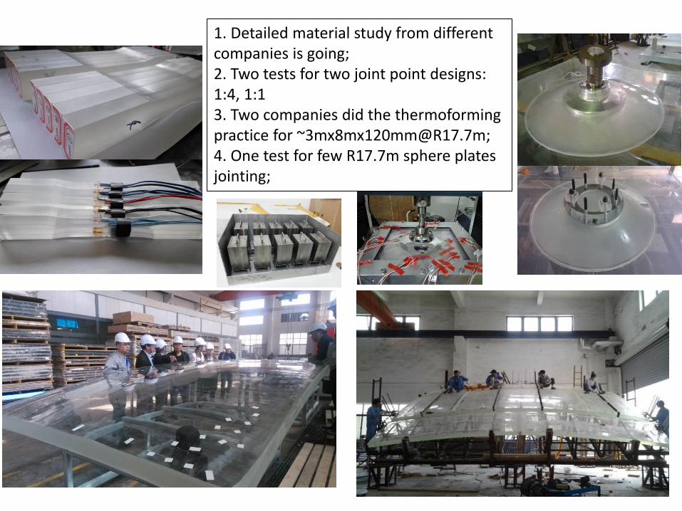
1. Detailed material study from different companies is going; 2. Two tests for two joint point designs: 1:4, 1:1 3. Two companies did the thermoforming practice for [email protected]; 4. One test for few R17.7m sphere plates jointing;

PMT coverage
PMT No. : ~18000 PMT coverage: ~78%
6
20” PMTs with structure Installation gap: ~2cm
Preliminary
Single PMT in layers
Triangle Regular hexagon Mixed Quadrilateral Football Volleyball
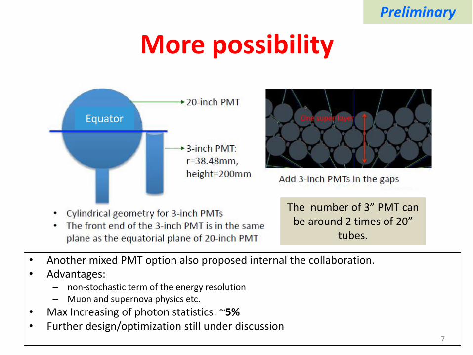
More possibility
• Another mixed PMT option also proposed internal the collaboration. • Advantages:
– non-stochastic term of the energy resolution – Muon and supernova physics etc.
• Max Increasing of photon statistics: ~5% • Further design/optimization still under discussion
7
Equator
Preliminary
The number of 3” PMT can be around 2 times of 20”
tubes.
LS R (m) (Cut 0.7MeV)
PMT
(Hz)
Acrylic (Hz)
(10ppt)
Strut (steel)
(Hz)
Fastener
(Cu) (Hz)
SUM
(Hz)
LS
(Hz)
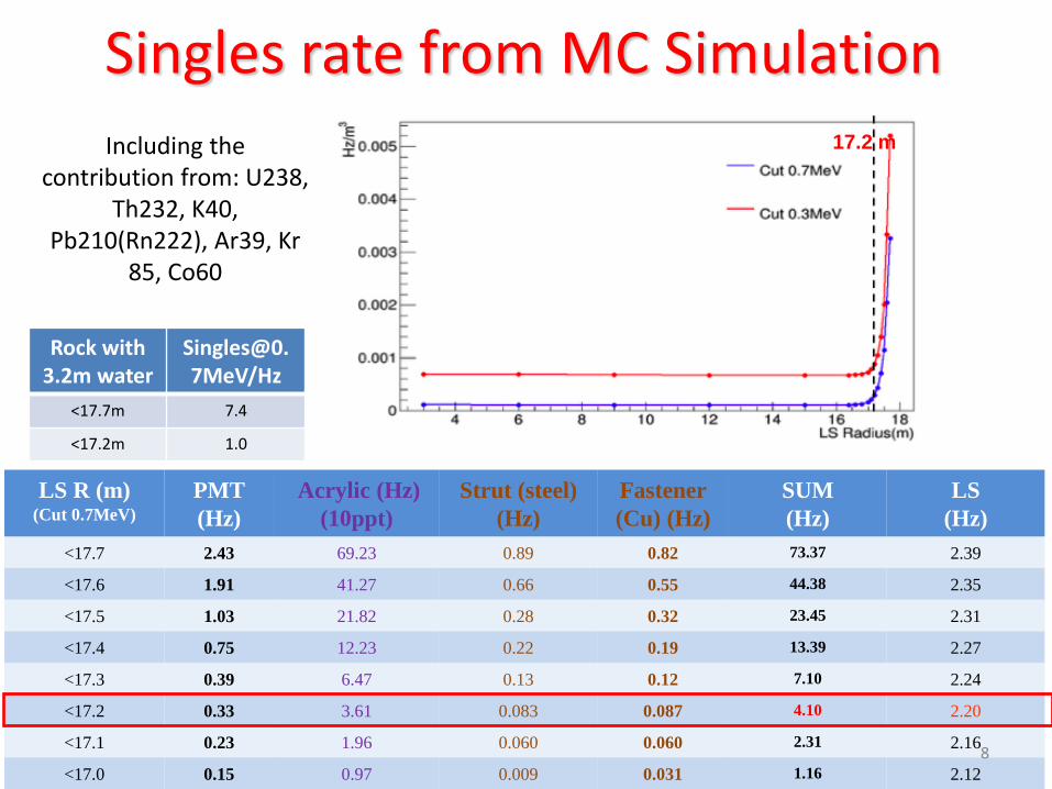
<17.7 2.43 69.23 0.89 0.82 73.37 2.39
<17.6 1.91 41.27 0.66 0.55 44.38 2.35
<17.5 1.03 21.82 0.28 0.32 23.45 2.31
<17.4 0.75 12.23 0.22 0.19 13.39 2.27
<17.3 0.39 6.47 0.13 0.12 7.10 2.24
<17.2 0.33 3.61 0.083 0.087 4.10 2.20
<17.1 0.23 1.96 0.060 0.060 2.31 2.16
<17.0 0.15 0.97 0.009 0.031 1.16 2.12
Singles rate from MC Simulation
Including the contribution from: U238,
Th232, K40, Pb210(Rn222), Ar39, Kr
85, Co60
17.2 m
Rock with 3.2m water
<17.7m 7.4
<17.2m 1.0
8

Reconstruction • PMT reconstruction
– Charge and time – Pulse Shape Discrimination
• Point-like source reconstruction – Energy and vertex
• Tracking at high energy – Direction and track length
• Tracking at low energy – Direction – Supernova, solar neutrinos
likelihood
Point like: <10cm@1MeV when PMT time resolution better than 4ns; <35cm@1MeV for charge only;
9

10
With the designed geometry, parameters, the detector will be better than 3%@1MeV energy resolution
While the total internal reflection at large radius, reconstruction algorithm still need improvement
Energy response
total charge-based energy reconstruction with an ideal vertex reconstruction
After vertex-dep. correction
Uniformly Distributed Events

11
Onsite Status
Final state
Now

• Civil engineering design finalized • Both vertical shaft and slope tunnel
going well. • In 2015, expected:
– Vertical shaft completed (totally ~611 meters)
– Slope tunnel, 900 meters (totally ~1340m)
12

Project Plan and Progresses
• Civil construction:2015-2017 • Detector component production:2016-2017 • PMT production:2016-2019 • Detector assembly & installation:2018-2019 • Filling & data taking:2020 13
First get-together meeting
2013 2014
Funding from CAS: “Strategic Leading Science & Technology Programme” approved (~CD1)
Funding(2013-2014) review
approved
Kaiping Neutrino Research Center established
Geological survey and preliminary civil design
Civil/infrastructure construction bidding
Yangjiang NPP started to build the last two cores
1st 20” MCP-PMT
Collaboration formed
Civil design approved
Groundbreaking Ceremony
CD option selected
2015

JUNO Detector Prototype
• Goal: Study/Comparison of PMTs’ performances in a real LS detector – MCP-PMT 8”+20”, Hainan Zhanchuang (HZC) 9”, Hamamatsu
8”+20” – Parameters:
• Effective Efficiency (Earth_magnetic_field×quantum×collection)
• Timing • Full dynamic range test with LS + waveform electronics • Background/noise in detector
• Other possibilities – PMT potting – PMT supporting – Waveform readout – LS background … – ……
14

Concept design • LS vessel: ø0.5m acrylic sphere
– ~56kg LAB LS
• Outer vessel: ø2m × 2m (DYB prototype used) – Pure water buffer ~75cm – ~7ton pure water
• Outer Shielding: ~1m (w.m.e.) • Water tank • LEAD + Polypropylene(PP)
• PMT number: ~51, Coverage: ~56%,
– 20”: H 4, MCP 8; – 8”: H 10, MCP 19; – 9”: HZC 10; – Resolution: ~4%@1MeV e-
• Electronics: – Waveform readout – Positive HV
• Trigger rates: – <~100Hz@>0.7MeV (water buffer)
• Calibration: – Optical and radioactive source
15
Water
~1m

Water
thicknes
s (cm)
75 95 110 130 150 170 200
Event
rate(Hz)
620.99 180.99 73.55 22.78 7.28 2.40 0.48
U238:10ppm Th232:30ppm K40:5ppm Detector and water surrounded by rock
Trigger rates: <~100Hz
Muon: ~30Hz PMT: <~10Hz@>0.7MeV, ~25cm water buffer
LS: <~1Hz Environment: <~20Hz (75cm LAB +1m water)
Radon surrounding <5Hz Material: <~20Hz
Water shielding effect:
~0.5Hz
~7.2Hz
JUNO
Prototype
16

17
LS vessel
ø50cm
Thickness ~1cm
Neck Height ~80cm ø5cm
20”
8” & 9”
Bottom PMT 8” & 9”
Detector design
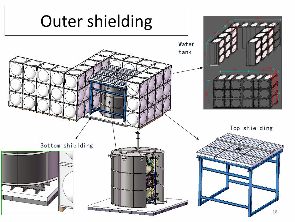
Outer shielding Water tank
Top shielding
Bottom shielding
18

PMT support
19
H 20” MCP 20” HZC 9” H 8” MCP 8”
PMT with structure tested
in water.
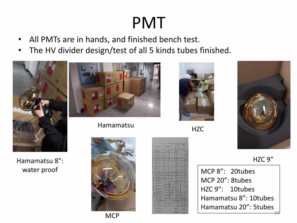
PMT • All PMTs are in hands, and finished bench test. • The HV divider design/test of all 5 kinds tubes finished.
20
Hamamatsu HZC
MCP
Hamamatsu 8”: water proof
HZC 9”
MCP 8”: 20tubes MCP 20”: 8tubes HZC 9”: 10tubes Hamamatsu 8”: 10tubes Hamamatsu 20”: 5tubes
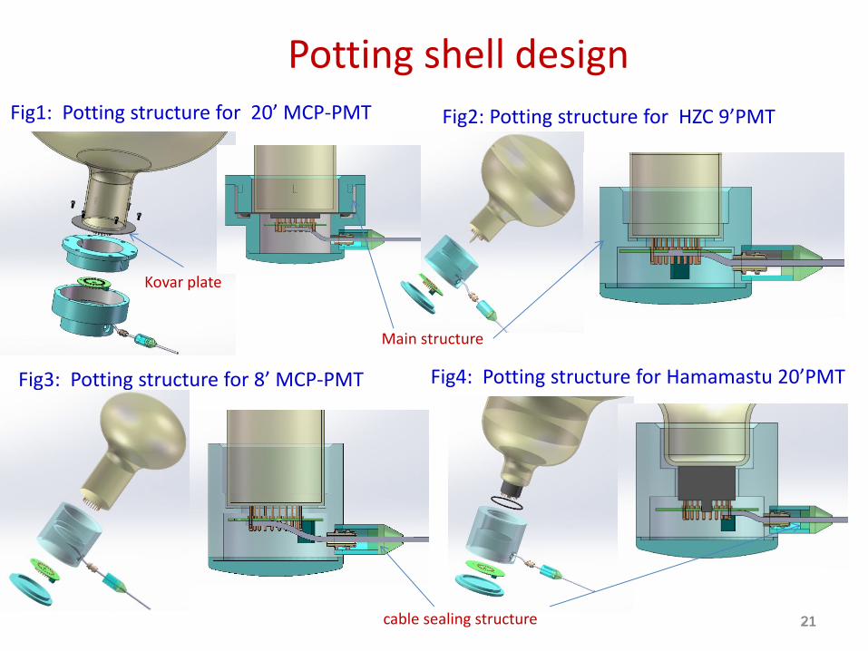
Fig1: Potting structure for 20’ MCP-PMT
Fig3: Potting structure for 8’ MCP-PMT
Potting shell design
Fig4: Potting structure for Hamamastu 20’PMT
Fig2: Potting structure for HZC 9’PMT
Main structure
cable sealing structure
Kovar plate
21 21

Potted PMT
Step2. assemble base and cable
Step1. assemble the acrylic shell
Step3.Casting the potting sealant and cover the cap
22
Tested in water for >5atm @>24hours;
More potting/testing going well.

Electronics • 1GHz sampling electronics • Front-end amplification board
– Design completed, test is ongoing
• ADC & Data collection board – Production is completed. Firmware testing
• Fan-out board – production is completed.
• Threshold & Cal Selection: – Designing, complete soon
• More Tests ongoing
23

24

25

Summary • JUNO central detector option selected: acrylic vessel. • Principle designed, calculated with simulation for response,
background, reconstruction, etc. • Onsite civil construction going well. • Detector R&D going well. • Prototyping for PMT, potting, LS, electronics, analysis etc. going on. • JUNO prototype will running soon.
26

Thanks for your attention!
27

Backup

JUNO detector
29

Optical parameters in simulation
Reemission probability PMT QE
emission spectrum
PMT CE
LS
Light yield: 11522/MeV
Absorption length: 77m@430nm
Rayleigh scattering length: 27m@430nm
Attenuation length: 20m@430nm
Water
Absorption length: 27m@430nm
Refractive index
30
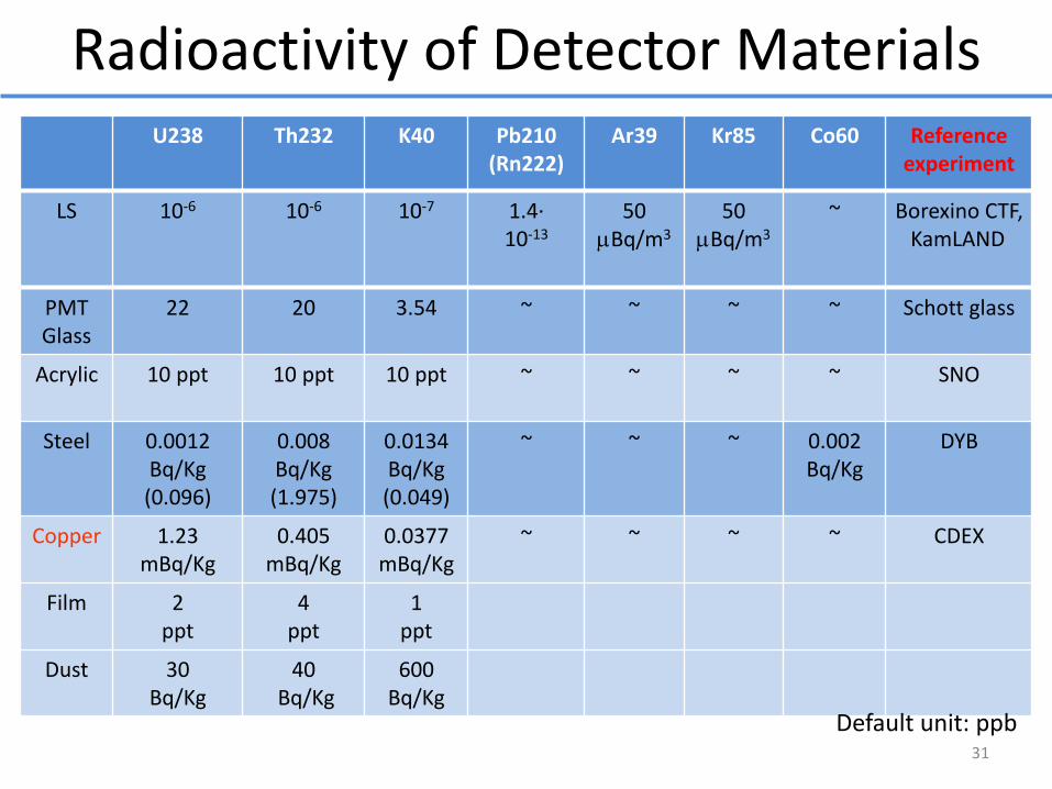
Radioactivity of Detector Materials U238 Th232 K40 Pb210
(Rn222) Ar39 Kr85 Co60 Reference
experiment
LS 10-6 10-6 10-7 1.4· 10-13
50 mBq/m3
50 mBq/m3
~ Borexino CTF, KamLAND
PMT Glass
22 20 3.54 ~ ~ ~ ~ Schott glass
Acrylic 10 ppt 10 ppt 10 ppt ~ ~ ~ ~ SNO
Steel 0.0012 Bq/Kg (0.096)
0.008 Bq/Kg (1.975)
0.0134 Bq/Kg (0.049)
~ ~ ~ 0.002 Bq/Kg
DYB
Copper 1.23 mBq/Kg
0.405 mBq/Kg
0.0377 mBq/Kg
~ ~ ~ ~ CDEX
Film 2 ppt
4 ppt
1 ppt
Dust 30 Bq/Kg
40 Bq/Kg
600 Bq/Kg
Default unit: ppb 31
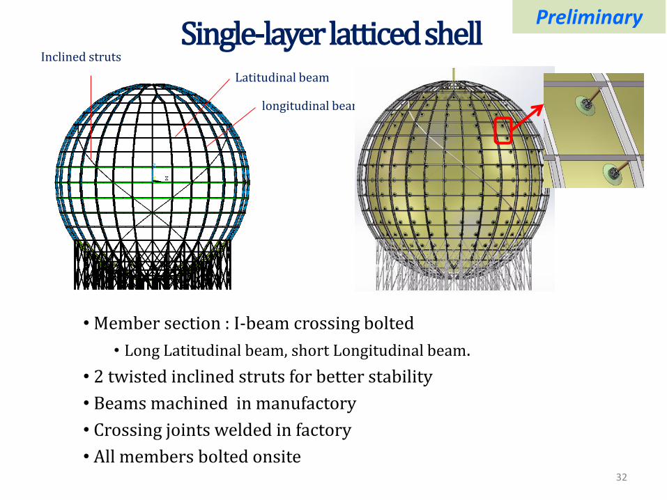
Single-layer latticed shell Latitudinal beam
longitudinal beam
Inclined struts
• Member section : I-beam crossing bolted
• Long Latitudinal beam, short Longitudinal beam.
• 2 twisted inclined struts for better stability
• Beams machined in manufactory
• Crossing joints welded in factory
• All members bolted onsite
Preliminary
32

Photons lost because of stainless steel support
struts shadowing
Preliminary
33
Struts totally 480: occupied 1 PMT: 86%, occupied 2 PMT: 14%; Decrease coverage ~3% Struts
Struts and shadowing effect

PMT base • All designed bases have been tested and working
well.
34
MCP 8” MCP 20” Hamamatsu 8” Hamamatsu 20”
HZC 9”
Factory
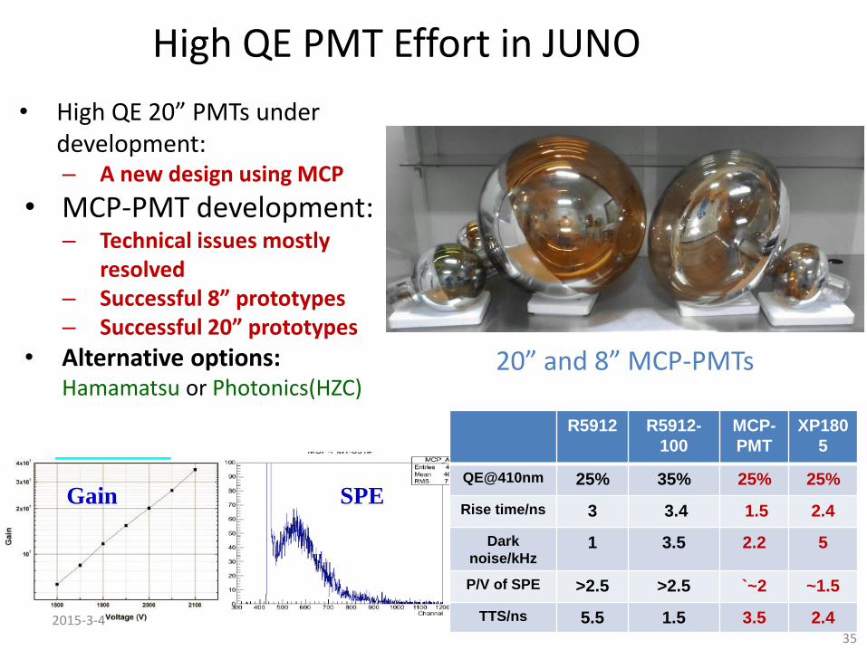
High QE PMT Effort in JUNO
• High QE 20” PMTs under development: – A new design using MCP
• MCP-PMT development: – Technical issues mostly
resolved – Successful 8” prototypes – Successful 20” prototypes
• Alternative options: Hamamatsu or Photonics(HZC)
SPE Gain
2015-3-4
35
R5912 R5912-
100
MCP-
PMT
XP180
5
QE@410nm 25% 35% 25% 25%
Rise time/ns 3 3.4 1.5 2.4
Dark
noise/kHz 1 3.5 2.2 5
P/V of SPE >2.5 >2.5 `~2 ~1.5
TTS/ns 5.5 1.5 3.5 2.4
20” and 8” MCP-PMTs