status and perspectives for digestate treatment - nitrogen...
TRANSCRIPT

BOKU, Dept. IFA-Tulln I Inst. f. Environmental Biotechnology I Werner FUCHS
Status and Perspectives for Digestate Treatment- Nitrogen Recovery as one Important Task forClosure of Nutrient Cycles
1
Werner Fuchs
University of Natural Resources and Life Sciences ViennaDept. IFA-TullnInst. f. Environmental BiotechnologyKonrad Lorenz Str. 20, A-3430 Tulln, Austria
BOKU, Dept. IFA-Tulln I Inst. f. Environmental Biotechnology I Werner FUCHS 2
Main drivers for application ofdigestate treatment
Legal restrictions regarding the amount of N applied per hectare via
livestock manure or agricultural wastes
European Nitrate Directive
National regulations
Landfarming is only applicable during the growing season
National regulations to providesufficient storage capacity for the winter period
Intensification of biogas production in regions with high
livestock densities
strong competition for land areawhere manure or fermentation residues can be applied
BOKU, Dept. IFA-Tulln I Inst. f. Environmental Biotechnology I Werner FUCHS 3
Expectations from digestate treatment
Cost savings
Reduction of transportations costs for application on farmland
Reduction of storage costs
Marketing of resulting products
Additional advantages
Decrease of N loss
Decrease of environmental burden

BOKU, Dept. IFA-Tulln I Inst. f. Environmental Biotechnology I Werner FUCHS 4
Overview ofpossible process combinations
Solid fractionSolid fraction
DryingDrying
Solid-liquidseparation
Solid-liquidseparation
DryingDrying
CompostingComposting
Liquid phaseLiquid phase
DigestateDigestate
Dried solidsDried solids
CompostCompost
Dried digestateDried digestate
UltrafiltrationUltrafiltration
StrippingStripping
Purified waterPurified water
Enhancedsolids removal
Enhancedsolids removal
Biologicaltreatment
Biologicaltreatment
PreconditioningPreconditioning
EvaporationEvaporation
Landapplication
Landapplication
Concentratedliquid
Concentratedliquid
Enhancedsolids removal
Enhancedsolids removal
Reverseosmosis
Reverseosmosis
N-reducedliquid
N-reducedliquid
Landapplication
Landapplication
Directdischarge
Directdischarge
Partially purifiedwater
Partially purifiedwater
Further treatment/Indirect discharge
Further treatment/Indirect discharge
Land application /Marketing
Land application /Marketing
Land application /Marketing
Land application /Marketing
Land application /Marketing
Land application /Marketing
Indirect discharge /Land application
Indirect discharge /Land application
BOKU, Dept. IFA-Tulln I Inst. f. Environmental Biotechnology I Werner FUCHS 5
Advantages of N-recovery
Increased amount of digestate applicable per hectare
Recovery of a valuable product - substitution of artificial fertilizers
Less ammonia emissions during drying of residual digestate
Enhancement of digester performance
High NH3 concentrations are inhibitory to microflora
N removal increases process stability using N rich substrates (chickenmanure, slaughterhouse waste)
Lower ammonia emissions from fertilized soils
BOKU, Dept. IFA-Tulln I Inst. f. Environmental Biotechnology I Werner FUCHS 6
Options for NH4-Recovery
Ammonia retention in the concentrated liquid phase by means ofmembrane processes
Ammonia transfer to the gas phase and recovery
Stripping
Evaporation
Membrane contactors
Ammonia precipitation as struvite in the liquid phase
N-Recovery from liquid by means of algae photo-reactors
BOKU, Dept. IFA-Tulln I Inst. f. Environmental Biotechnology I Werner FUCHS 77
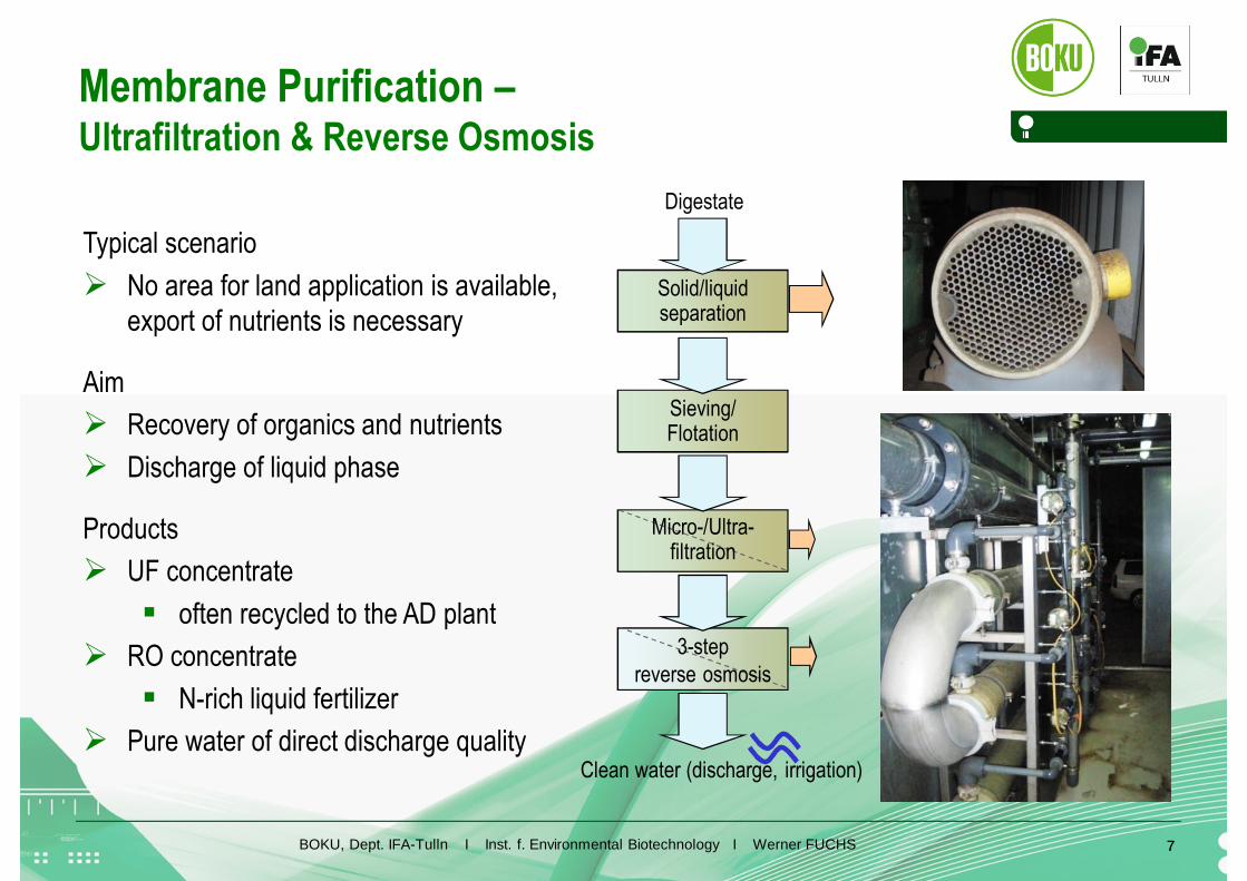
Typical scenario
No area for land application is available,export of nutrients is necessary
Aim
Recovery of organics and nutrients
Discharge of liquid phase
Products
UF concentrate
often recycled to the AD plant
RO concentrate
N-rich liquid fertilizer
Pure water of direct discharge quality
Membrane Purification –Ultrafiltration & Reverse Osmosis
Clean water (discharge, irrigation)
Micro-/Ultra-filtration
3-stepreverse osmosis
Solid/liquidseparation
Sieving/Flotation
Digestate
BOKU, Dept. IFA-Tulln I Inst. f. Environmental Biotechnology I Werner FUCHS 8
NH4-recovery with membranes
High practical experience available
RO membranes are very susceptible to particles→ complete suspend solids removal necessary
To high effort if only N-removal required
Un-dissociated NH3 easily passes the membrane Cooling necessary
Acidification necessary
Product: liquid fertilizer concentrate (RO concentrate) Contains NH4 + all organic/inorganic components (P, K, salts)
Not well defined
BOKU, Dept. IFA-Tulln I Inst. f. Environmental Biotechnology I Werner FUCHS 9
0%
20%
40%
60%
80%
100%
4,0 5,0 6,0 7,0 8,0 9,0 10,0 11,0 12,0S
ha
reof
am
mon
ia[%
]
pH [-]
120 C
100 C
40 C
60 C
20 C
80 C
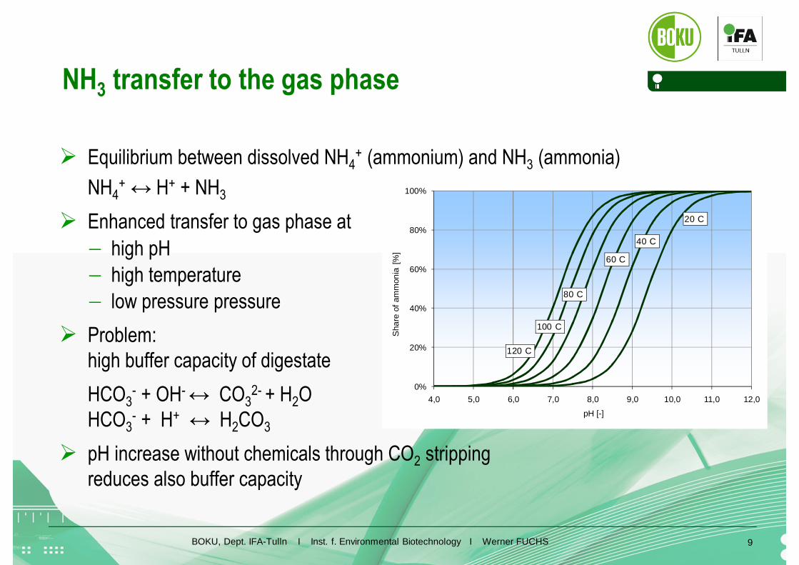
NH3 transfer to the gas phase
Equilibrium between dissolved NH4+ (ammonium) and NH3 (ammonia)
NH4+ ↔ H+ + NH3
Enhanced transfer to gas phase at
high pH
high temperature
low pressure pressure
Problem:high buffer capacity of digestate
HCO3- + OH- ↔ CO3
2- + H2OHCO3
- + H+ ↔ H2CO3
pH increase without chemicals through CO2 strippingreduces also buffer capacity
BOKU, Dept. IFA-Tulln I Inst. f. Environmental Biotechnology I Werner FUCHS
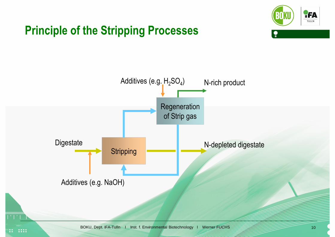
Principle of the Stripping Processes
10
Stripping
Regenerationof Strip gas
Digestate N-depleted digestate
N-rich product
Additives (e.g. NaOH)
Additives (e.g. H2SO4)
BOKU, Dept. IFA-Tulln I Inst. f. Environmental Biotechnology I Werner FUCHS 1111
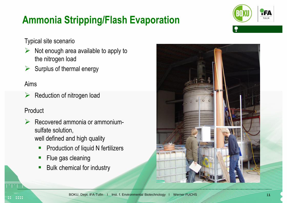
Typical site scenario
Not enough area available to apply tothe nitrogen load
Surplus of thermal energy
Aims
Reduction of nitrogen load
Product
Recovered ammonia or ammonium-sulfate solution,well defined and high quality
Production of liquid N fertilizers
Flue gas cleaning
Bulk chemical for industry
Ammonia Stripping/Flash Evaporation

BOKU, Dept. IFA-Tulln I Inst. f. Environmental Biotechnology I Werner FUCHS 12
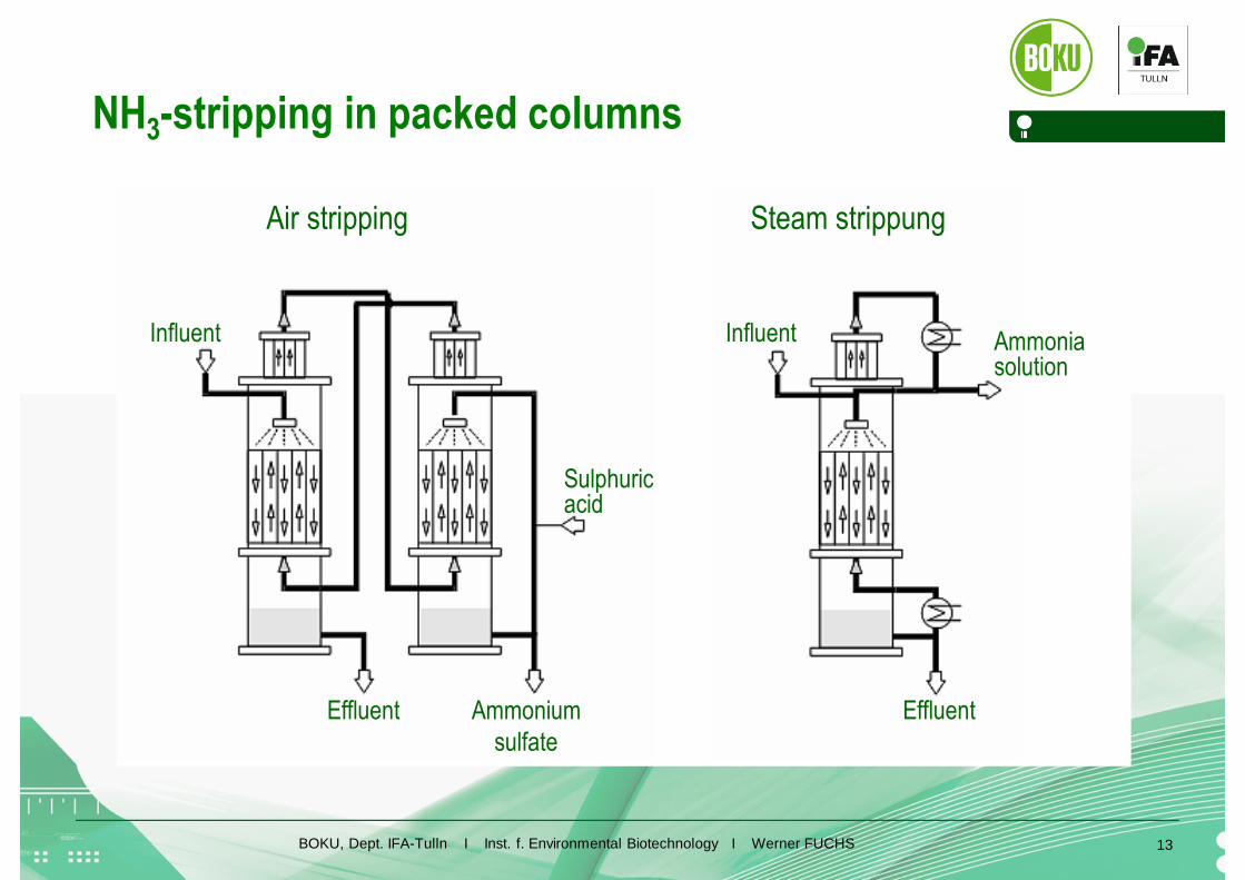
Stripping technologies
Air/gas stripping
Medium temperature level (excess thermal energy from CHP plant)
High air flow rate → increased electrical energy
Addition of NaOH to increase pH
Ammonia recovered in a scrubber as ammonium sulfate
Steam stripping
High temperature level for steam production(usually not available from CHP plant)
Low electrical energy demand
Ammonia recovered by condensation as ammonia solution
BOKU, Dept. IFA-Tulln I Inst. f. Environmental Biotechnology I Werner FUCHS 13
NH3-stripping in packed columns
Air stripping Steam strippung
Ammoniasolution
EffluentEffluent Ammoniumsulfate
Sulphuricacid
Influent Influent

BOKU, Dept. IFA-Tulln I Inst. f. Environmental Biotechnology I Werner FUCHS 14
Treateddigeste
Scrubbingcolumn
Stripping airrecirculation
NH -stripping
3
Acid dosage(H SO )2 4
Basedosage(NaOH) Collection tank
ammoniumsulfate
Digestatestorage tank
CO -stripping
2
BOKU, Dept. IFA-Tulln I Inst. f. Environmental Biotechnology I Werner FUCHS 15
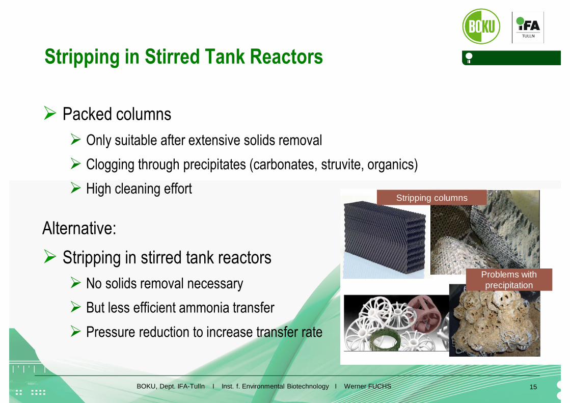
Stripping in Stirred Tank Reactors
Packed columns
Only suitable after extensive solids removal
Clogging through precipitates (carbonates, struvite, organics)
High cleaning effort
Alternative:
Stripping in stirred tank reactors
No solids removal necessary
But less efficient ammonia transfer
Pressure reduction to increase transfer rate
Problems withprecipitation
Stripping columns

BOKU, Dept. IFA-Tulln I Inst. f. Environmental Biotechnology I Werner FUCHS 16
Anastrip-Process
Semi continuous processusing 2 stirred tank reactors
Stripping gas: released CO2
Process conditions:T ≤ 80 °C, P ~ 350 - 400 mbar
New ammonia capture technique
Released NH3 + CO2converted with FGD (flue-gas desulfurization)-Gypsum, CaSO4
Products: Ammonium sulfate + CaCO3
Advantage
No solid liquid separation required
Integrated into biogas process, reduction of N-inhibition
Disadvantage: high investment costs
Stripreactor I
Stripreactor II
Product
NH4recovery
BOKU, Dept. IFA-Tulln I Inst. f. Environmental Biotechnology I Werner FUCHS 17
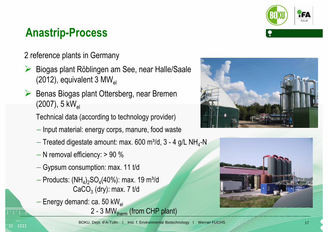
Anastrip-Process
2 reference plants in Germany
Biogas plant Röblingen am See, near Halle/Saale(2012), equivalent 3 MWel
Benas Biogas plant Ottersberg, near Bremen(2007), 5 kWel
Technical data (according to technology provider)
Input material: energy corps, manure, food waste
Treated digestate amount: max. 600 m³/d, 3 - 4 g/L NH4-N
N removal efficiency: > 90 %
Gypsum consumption: max. 11 t/d
Products: (NH4)2SO4(40%): max. 19 m³/dCaCO3 (dry): max. 7 t/d
Energy demand: ca. 50 kWel
2 - 3 MWtherm (from CHP plant)
BOKU, Dept. IFA-Tulln I Inst. f. Environmental Biotechnology I Werner FUCHS
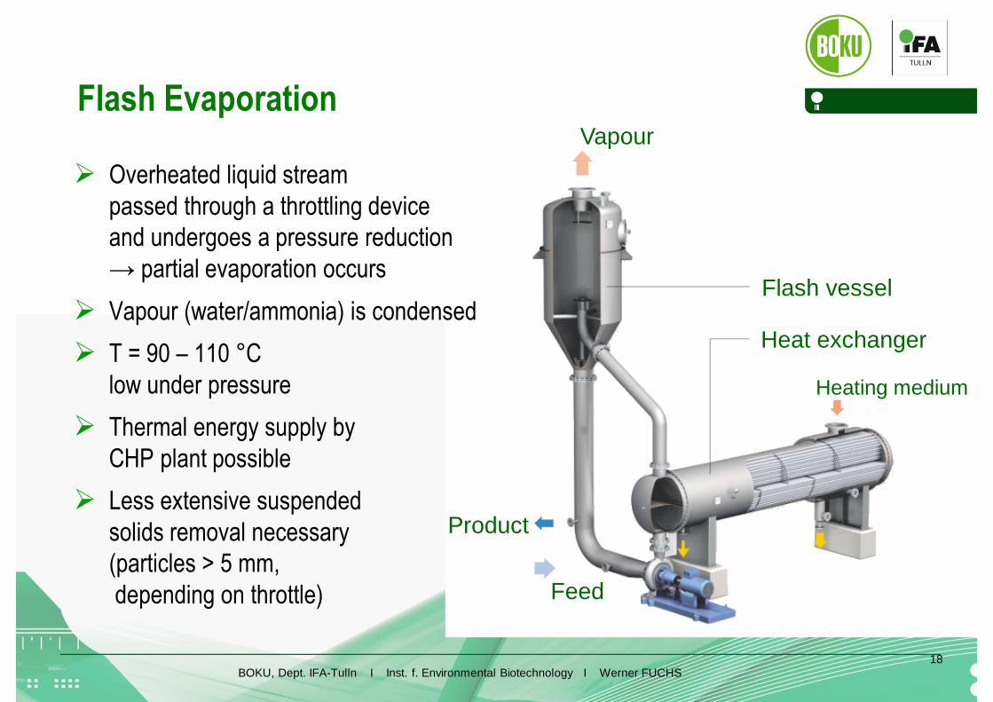
Vapour
Product
Feed
Heat exchanger
Flash vessel
Heating medium
18
Flash Evaporation
Overheated liquid streampassed through a throttling deviceand undergoes a pressure reduction→ partial evaporation occurs
Vapour (water/ammonia) is condensed
T = 90 – 110 °Clow under pressure
Thermal energy supply byCHP plant possible
Less extensive suspendedsolids removal necessary(particles > 5 mm,depending on throttle)

BOKU, Dept. IFA-Tulln I Inst. f. Environmental Biotechnology I Werner FUCHS 19
Flash evaporation
Well established technology fortreatment of N-rich effluents
Can be operated withhigher particle content
Little experience as technologyfor biogas plants
Proposed by acouple of companies
No detailedinformation available

BOKU, Dept. IFA-Tulln I Inst. f. Environmental Biotechnology I Werner FUCHS 20
Membrane Contactors
Hydrophobic hollow-fibre membraneswith gas filled pores
Submerged in the digestate
Sulphuric acid is circulated through the lumen of the fibres
Driving force for NH3 transfer:Difference in partial pressure between digestate and sulphuric acid.
Membrane
NH3
(NH ) SO4 2 4
H SO2 4
Digestate
BOKU, Dept. IFA-Tulln I Inst. f. Environmental Biotechnology I Werner FUCHS 21
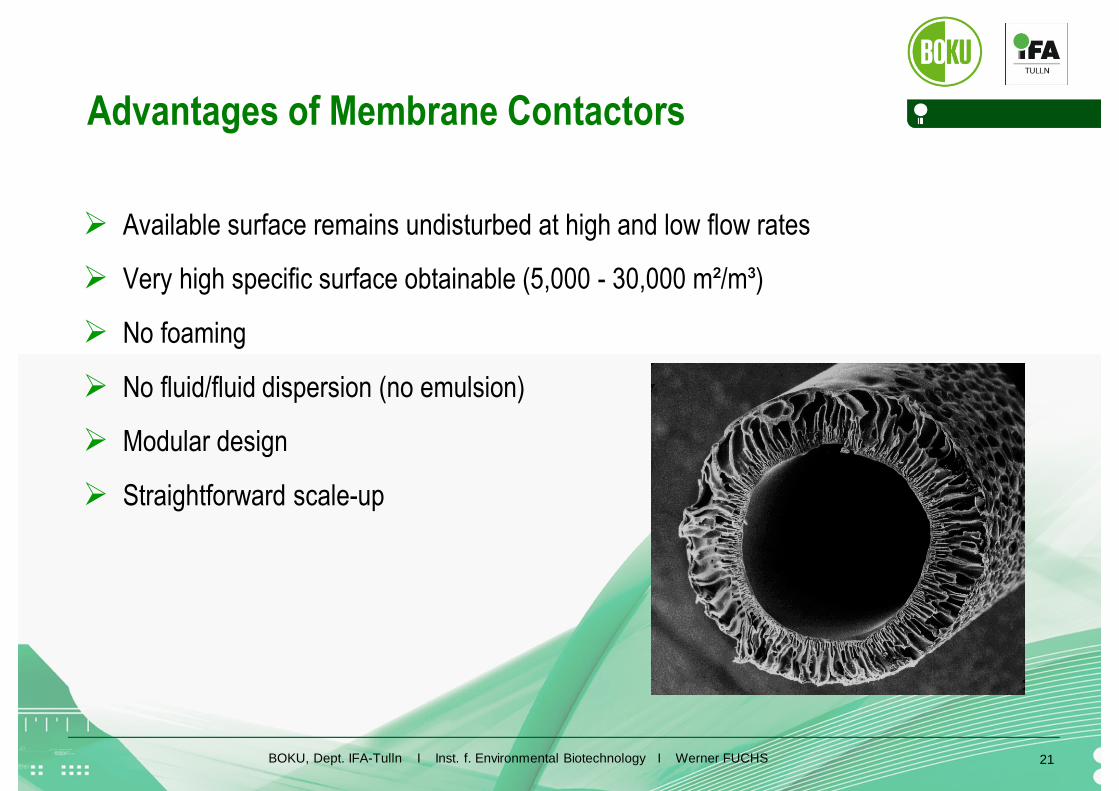
Advantages of Membrane Contactors
Available surface remains undisturbed at high and low flow rates
Very high specific surface obtainable (5,000 - 30,000 m²/m³)
No foaming
No fluid/fluid dispersion (no emulsion)
Modular design
Straightforward scale-up
BOKU, Dept. IFA-Tulln I Inst. f. Environmental Biotechnology I Werner FUCHS 22
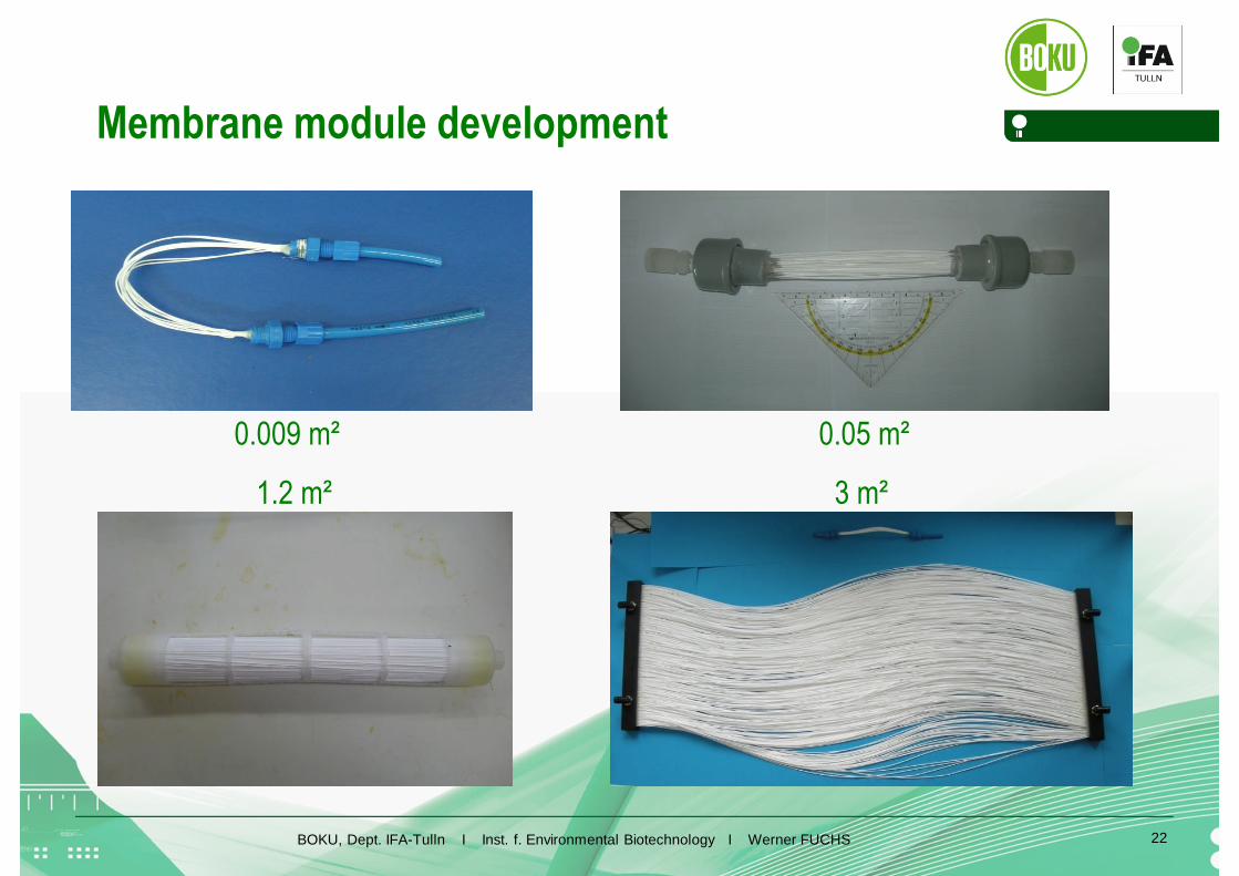
Membrane module development
1.2 m² 3 m²
0.009 m² 0.05 m²
BOKU, Dept. IFA-Tulln I Inst. f. Environmental Biotechnology I Werner FUCHS
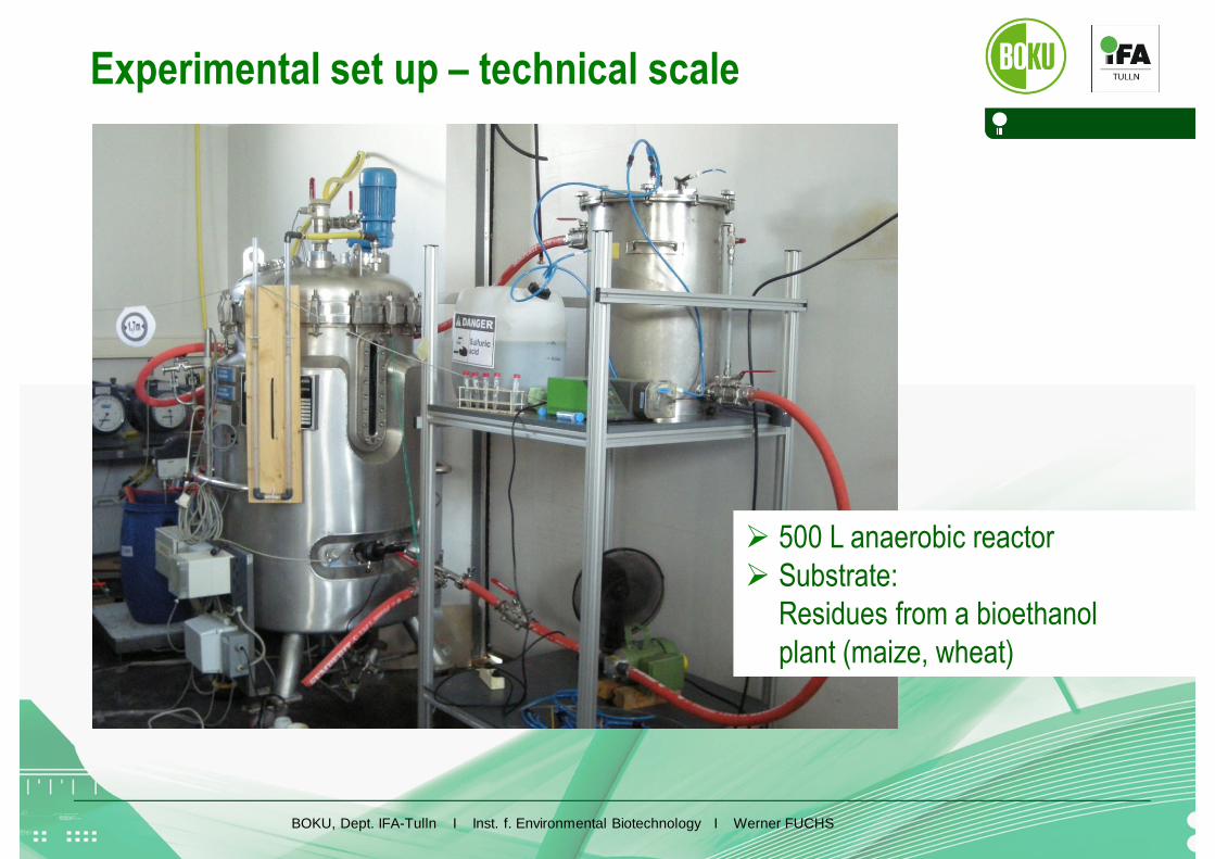
Experimental set up – technical scale
500 L anaerobic reactor Substrate:
Residues from a bioethanolplant (maize, wheat)
BOKU, Dept. IFA-Tulln I Inst. f. Environmental Biotechnology I Werner FUCHS December13, 2011
24
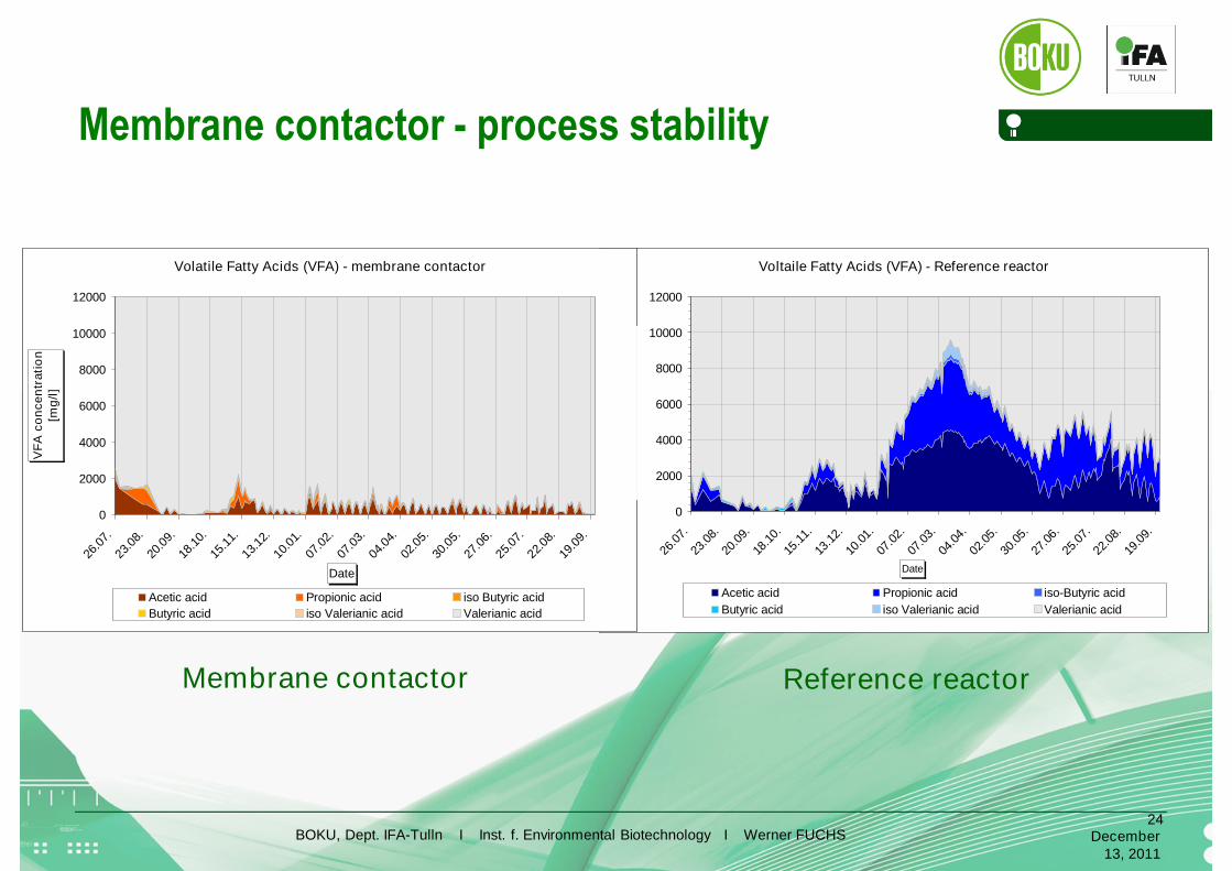
Membrane contactor - process stability
Voltaile Fatty Acids (VFA) - Reference reactor
0
2000
4000
6000
8000
10000
12000
26.0
7.
23.0
8.
20.0
9.
18.1
0.
15.1
1.
13.1
2.
10.0
1.
07.0
2.
07.0
3.
04.0
4.
02.0
5.
30.0
5.
27.0
6.
25.0
7.
22.0
8.
19.0
9.
Date
VF
AC
on
ce
ntr
ati
on
[mg
/l]
Acetic acid Propionic acid iso-Butyric acid
Butyric acid iso Valerianic acid Valerianic acid
Volatile Fatty Acids (VFA) - membrane contactor
0
2000
4000
6000
8000
10000
12000
26.0
7.
23.0
8.
20.0
9.
18.1
0.
15.1
1.
13.1
2.
10.0
1.
07.0
2.
07.0
3.
04.0
4.
02.0
5.
30.0
5.
27.0
6.
25.0
7.
22.0
8.
19.0
9.
Date
VF
Aco
nce
ntr
ati
on
[mg
/l]
Acetic acid Propionic acid iso Butyric acid
Butyric acid iso Valerianic acid Valerianic acid
Membrane contactor Reference reactor

BOKU, Dept. IFA-Tulln I Inst. f. Environmental Biotechnology I Werner FUCHS
Gas Volume
30000
40000
50000
60000
70000
80000
90000
100000
110000
120000
130000
18.11.
07.01.
26.02.
17.04.
06.06.
26.07.
14.09.
Date
To
tal
Ga
sv
olu
me
[ml]
30000
40000
50000
60000
70000
80000
90000
100000
110000
120000
130000
Reference Reactor Membrane Contactor
Membrane contactor – biogas production
BOKU, Dept. IFA-Tulln I Inst. f. Environmental Biotechnology I Werner FUCHS 26
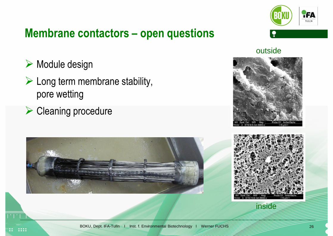
Membrane contactors – open questions
Module design
Long term membrane stability,pore wetting
Cleaning procedure
outside
inside

BOKU, Dept. IFA-Tulln I Inst. f. Environmental Biotechnology I Werner FUCHS 27
Conclusions
N-recovery helps to overcome limited area availabilityand to recover N as a valuable product
A variety of strategies and technical solutions existbut limited number of full scale installations
Membrane treatment (UF+RO) is only meaningfulif complete digestate treatment is required
Stripping in stirred tank reactors has high potential,reference plants are available
Flash evaporation is very reasonable technology,applicability for digestate treatment needs to be demonstrated
Membrane contactors are a promising technologybut only in the beginning of its development

BOKU, Dept. IFA-Tulln I Inst. f. Environmental Biotechnology I Werner FUCHS 28
Thank you for your attention