statics - İtÜweb.itu.edu.tr/~ustunda1/course/staticsc04_05_22102013.pdf · • determine the...
TRANSCRIPT
Force System Resultants4
STATICSAssist. Prof. Dr. Cenk Üstündağ
Chapter Objectives
• Method for finding the moment of a force about a specified axis.
• Define the moment of a couple.• Determine the resultants of non-concurrent force
systems• Reduce a simple distributed loading to a resultant force
having a specified location

Chapter Outline
5. Moment of a Force about a Specified Axis6. Moment of a Couple7. Simplification of a Force and Couple System8. Further Simplification of a Force and Couple System9. Reduction of a Simple Distributed Loading
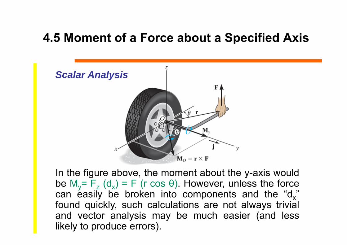
4.5 Moment of a Force about a Specified Axis
In the figure above, the moment about the y-axis wouldbe My= Fz (dx) = F (r cos θ). However, unless the forcecan easily be broken into components and the “dx”found quickly, such calculations are not always trivialand vector analysis may be much easier (and lesslikely to produce errors).
Scalar Analysis

4.5 Moment of a Force about a Specified Axis
First compute the moment of Fabout any arbitrary point O that lies on the a’- a axis using the cross product.
MO = r F
Now, find the component of MO along the a-axis using the dot product.
Ma’-a = ua • MO
Our goal is to find the moment of F (the tendency to rotate the body) about the a-axis.
Vector Analysis

4.5 Moment of a Force about a Specified Axis
Vector AnalysisM a can also be obtained as
The above equation is also called the triple scalar product.
In this equation,ua represents the unit vector along the a-axis,r is the position vector from any point on the a-axis to any point A on the line of action of the force, andF is the force vector.

Example
Determine the moment produced by the force F which tends to rotate the rod about the AB axis.

Solution
Solution on whiteboard

4.6 Moment of a Couple
The moment of a couple is defined as
MO = Fd (using a scalar analysis) or as
MO = r F (using a vector analysis).
Here r is any position vector from the line of action of F to the line of action of F.
A couple is defined as twoparallel forces with the samemagnitude but opposite indirection separated by aperpendicular distance “d.”

4.6 Moment of a Couple
The net external effect of a couple is thatthe net force equals zero and themagnitude of the net moment equals F·d.

4.6 Moment of a Couple
Moments due to couples can be addedtogether using the same rules as addingany vectors.
Since the moment of a couple dependsonly on the distance between the forces,the moment of a couple is a free vector.It can be moved anywhere on the bodyand have the same external effect on thebody.
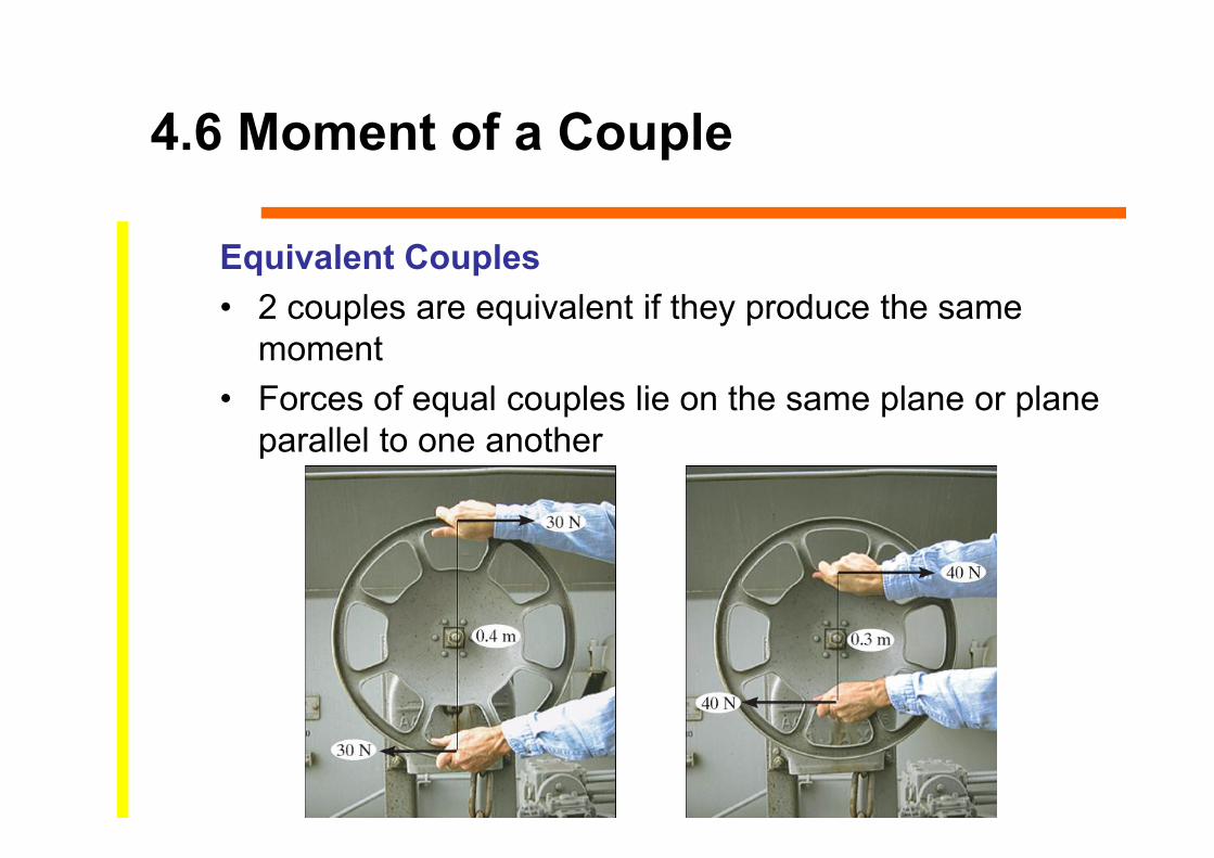
4.6 Moment of a Couple
Equivalent Couples• 2 couples are equivalent if they produce the same
moment• Forces of equal couples lie on the same plane or plane
parallel to one another

4.6 Moment of a Couple
Resultant Couple Moment• Couple moments are free vectors and may be applied
to any point P and added vectorially• For resultant moment of two couples at point P,
MR = M1 + M2
• For more than 2 moments,MR = ∑(r F)

Example
1) Add the two couples to find the resultant couple.
2) Equate the net moment to 1.5 kNm clockwise to find F.
Given: Two couples act on the beam with the geometry shown.
Find: The magnitude of F so that the resultant couple moment is 1.5 kNmclockwise.
Plan:

Solution
Solution:
The net moment is equal to:
+ M = – F (0.9) + (2) (0.3)
= – 0.9 F + 0.6
– 1.5 kNm = – 0.9 F + 0.6
Solving for the unknown force F, we get F = 2.33 kN
Example
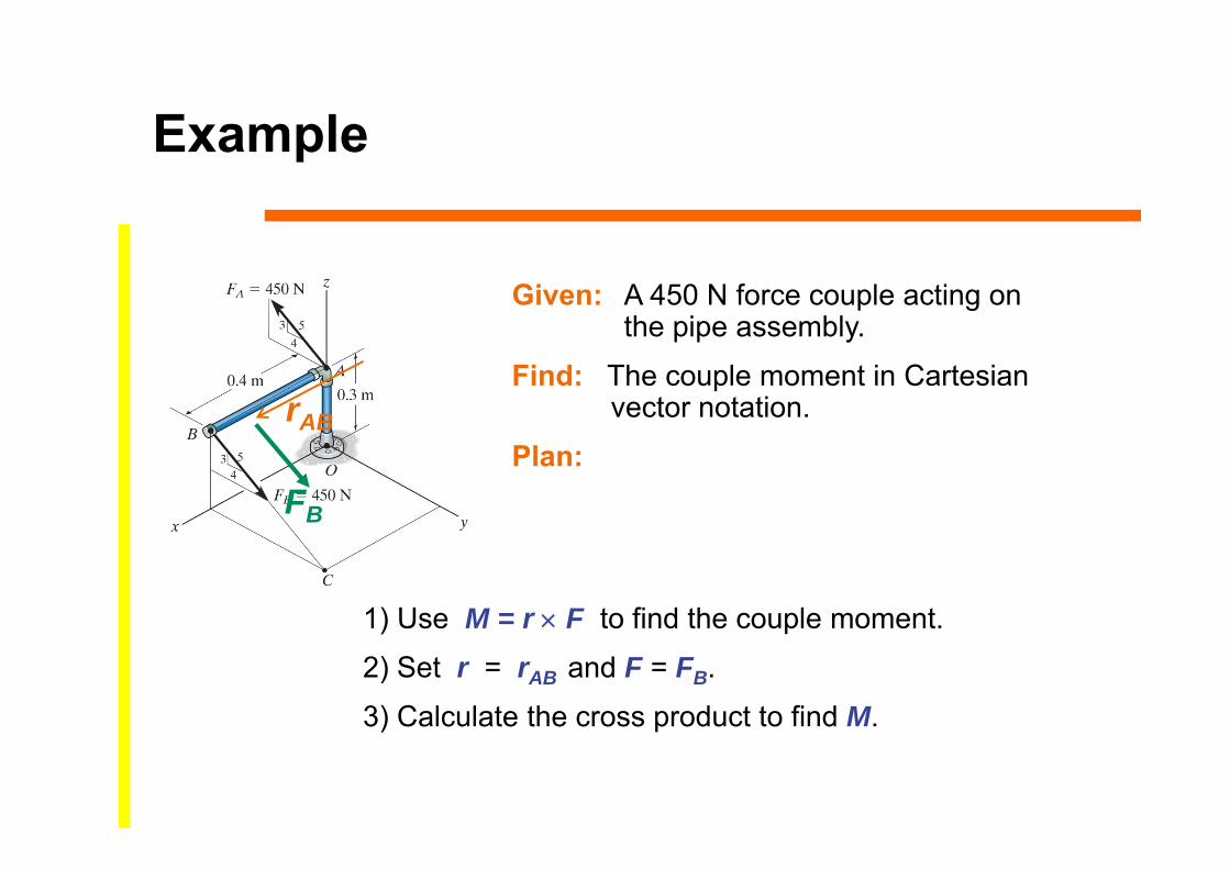
1) Use M = r F to find the couple moment.
2) Set r = rAB and F = FB.
3) Calculate the cross product to find M.
Given: A 450 N force couple acting on the pipe assembly.
Find: The couple moment in Cartesianvector notation.
Plan:rAB
FB

Solution
= [{0(-270) – 0(360)} i – {4(-270) – 0(0)} j + {0.4(360) – 0(0)} k] N·m
= {0 i + 108 j + 144 k} N·m
M = rAB FB
= N·mi j k
0.4 0 00 360 270
rAB = { 0.4 i } m
FB = {0 i + 450(4/5) j 450(3/5) k} N
= {0 i + 360 j 270 k} N rAB
FB
Solution:

Example
Determine the magnitude and direction of the couple moment acting on the gear.

Solution
Solution on whiteboard

4.7 Simplification of a Force and Couple System
When a number of forces and couple moments are acting on a body, it is easier to understand their overall effect on the body if they are combined into a single force and couple moment having the same external effect.
The two force and couple systems are called equivalent systems since they have the same external effect on the body.

4.7 Simplification of a Force and Couple System
MOVING A FORCE ON ITS LINE OF ACTION
Moving a force from A to B, when both points are on the vector’s line of action, does not change the external effect.
Hence, a force vector is called a sliding vector. (But the internal effect of the force on the body does depend on where the force is applied).
4.7 Simplification of a Force and Couple System
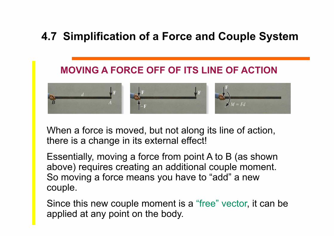
MOVING A FORCE OFF OF ITS LINE OF ACTION
When a force is moved, but not along its line of action, there is a change in its external effect!
Essentially, moving a force from point A to B (as shown above) requires creating an additional couple moment. So moving a force means you have to “add” a new couple.
Since this new couple moment is a “free” vector, it can be applied at any point on the body.
B

4.7 Simplification of a Force and Couple System
When several forces and couple moments act on a body, you can move each force and its associated couple moment to a common point O.
Now you can add all the forces and couple moments together and find one resultant force-couple moment pair.

4.7 Simplification of a Force and Couple System
If the force system lies in the x-y plane (a 2-D case), then the reduced equivalent system can be obtained using the following three scalar equations.
WR = W1 + W2(MR)o = W1 d1 + W2 d2

Example
1) Sum all the x and y components of the forces to find FRA.2) Find and sum all the moments resulting from moving each force
component to A.3) Shift FRA to a distance d such that d = MRA/FRy
Given: A 2-D force system with geometry as shown.
Find: The equivalent resultant force and couple moment acting at A and then the equivalent single force location measured from A.
Plan:
Solution
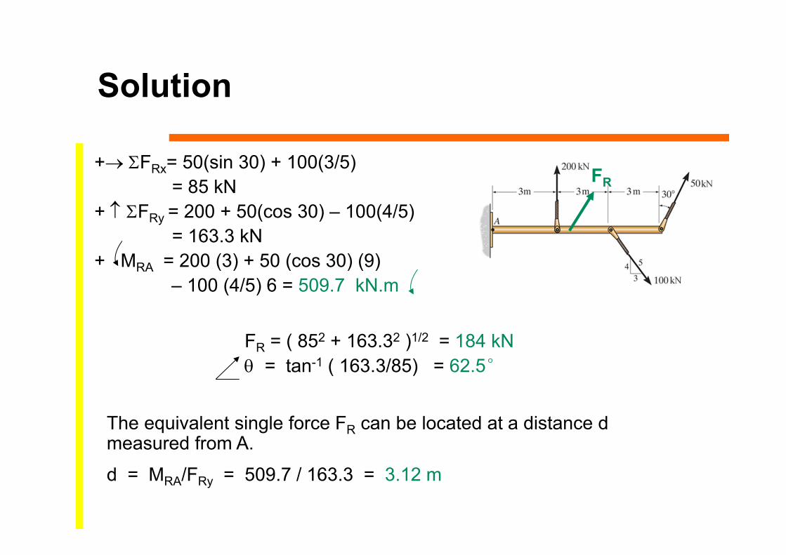
+ FRx= 50(sin 30) + 100(3/5)= 85 kN
+ FRy = 200 + 50(cos 30) – 100(4/5)= 163.3 kN
+ MRA = 200 (3) + 50 (cos 30) (9)– 100 (4/5) 6 = 509.7 kN.m
FR = ( 852 + 163.32 )1/2 = 184 kN = tan-1 ( 163.3/85) = 62.5°
The equivalent single force FR can be located at a distance d measured from A.
d = MRA/FRy = 509.7 / 163.3 = 3.12 m
FR

4.8 Further Simplification of a Force and Couple System
Concurrent Force System• A concurrent force system is where lines of action of
all the forces intersect at a common point O
FFR
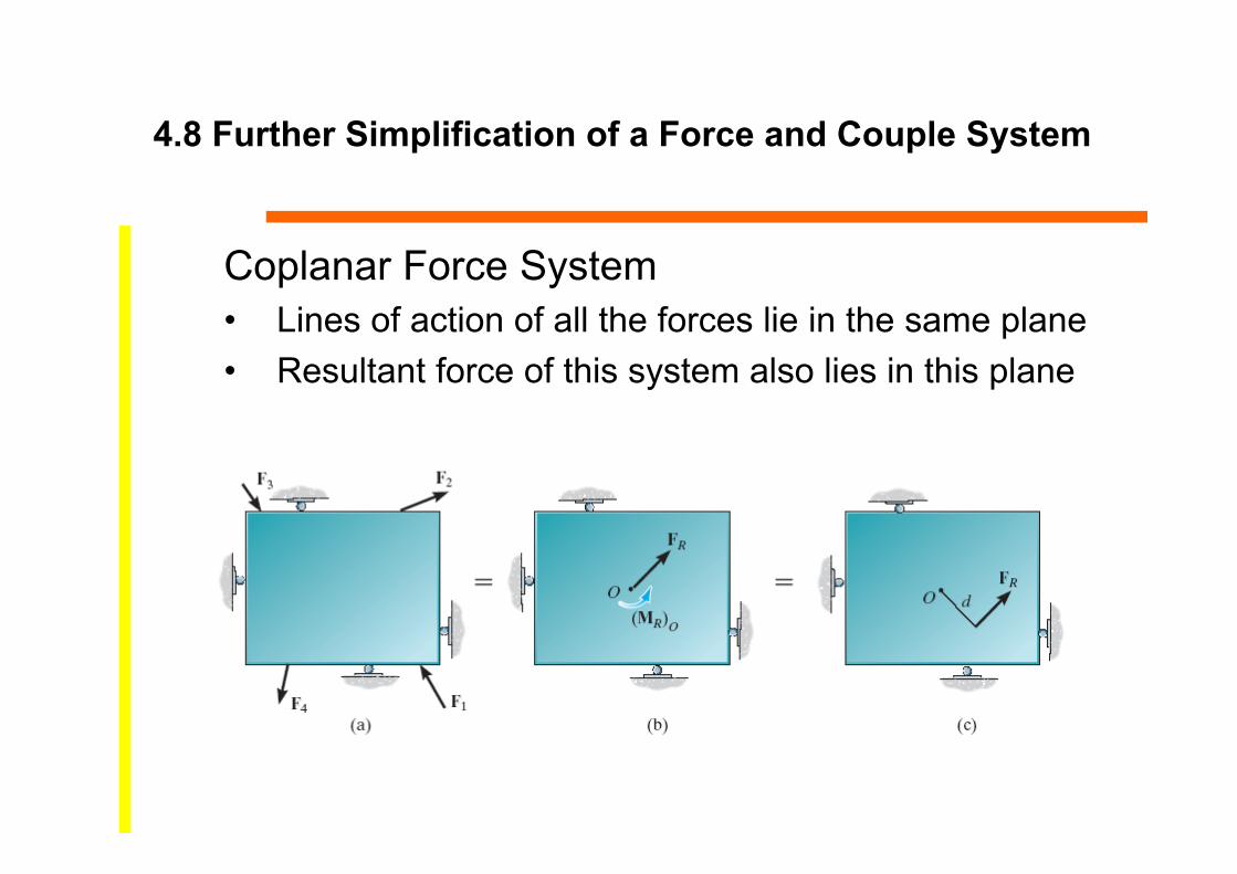
4.8 Further Simplification of a Force and Couple System
Coplanar Force System• Lines of action of all the forces lie in the same plane • Resultant force of this system also lies in this plane

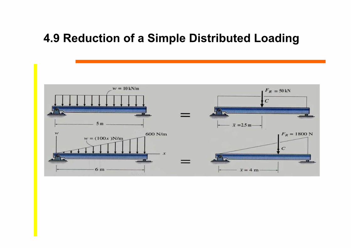
4.9 Reduction of a Simple Distributed Loading
• Large surface area of a body may be subjected to distributed loadings
• Loadings on the surface is defined as pressure• Pressure is measured in Pascal (Pa): 1 Pa = 1N/m2
Uniform Loading Along a Single Axis• Most common type of distributed
loading is uniform along a single axis

4.9 Reduction of a Simple Distributed Loading
Magnitude of Resultant Force• Magnitude of dF is determined from differential area dA
under the loading curve. • For length L,
• Magnitude of the resultant force is equal to the total area A under the loading diagram.
AdAdxxwFAL
R

4.9 Reduction of a Simple Distributed Loading
Location of Resultant Force• MR = ∑MO
• dF produces a moment of xdF = x w(x) dx about O• For the entire plate,
• Solving for
L
RORo dxxxwFxMM )(
x
A
A
L
L
dA
xdA
dxxw
dxxxwx
)(
)(
4.9 Reduction of a Simple Distributed Loading

Example
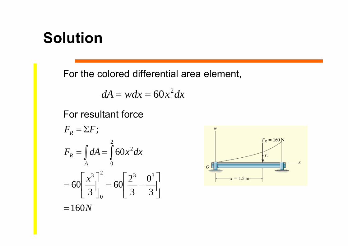
Determine the magnitude and location of the equivalent resultant force acting on the shaft.
Solution
For the colored differential area element,
For resultant force
dxxwdxdA 260
N
x
dxxdAF
FF
AR
R
160
30
3260
360
60
;
332
0
3
2
0
2

Solution
For location of line of action,
Checking,
mmax
mNmabA
5.1)2(43
43
1603
)/240(23
m
xdxxx
dA
xdAx
A
A
5.1
16040
4260
1604
60
160
)60(442
0
42
0
2

Equilibrium of a Rigid Body5
STATICSAssist. Prof. Dr. Cenk Üstündağ

Chapter Objectives
• Develop the equations of equilibrium for a rigid body• Concept of the free-body diagram for a rigid body• Solve rigid-body equilibrium problems using the
equations of equilibrium

Chapter Outline
1. Conditions for Rigid Equilibrium2. Free-Body Diagrams3. Equations of Equilibrium

5.1 Conditions for Rigid-Body Equilibrium
In contrast to the forces on a particle, the forces on a rigid-body are not usually concurrent and may cause rotation of the body (due to the moments created by the forces).
Forces on a particle
For a rigid body to be in equilibrium, the net force as well as the net moment about any arbitrary point O must be equal to zero.
F = 0 (no translation)
and MO = 0 (no rotation)
Forces on a rigid body

5.2 Free Body Diagrams
Finally, we need to apply the equations of equilibrium to solve for any unknowns.
For analyzing an actual physical system, first we need to create an idealized model (above right).
Then we need to draw a free-body diagram (FBD) showing all the external (active and reactive) forces.

5.2 Free Body Diagrams
2. Show all the external forces and couple moments.These typically include: a) applied loads, b) support reactions, and c) the weight of the body.
Idealized model Free-body diagram (FBD)
1. Draw an outlined shape. Imagine the body to be isolated or cut “free” from its constraints and draw its outlined shape.

5.2 Free Body Diagrams
3. Label loads and dimensions on the FBD: All known forces and couple moments should be labeled with their magnitudes and directions. For the unknown forces and couple moments, use letters like Ax, Ay, MA. Indicate any necessary dimensions.
Idealized model Free-body diagram (FBD)
5.2 Free Body Diagrams
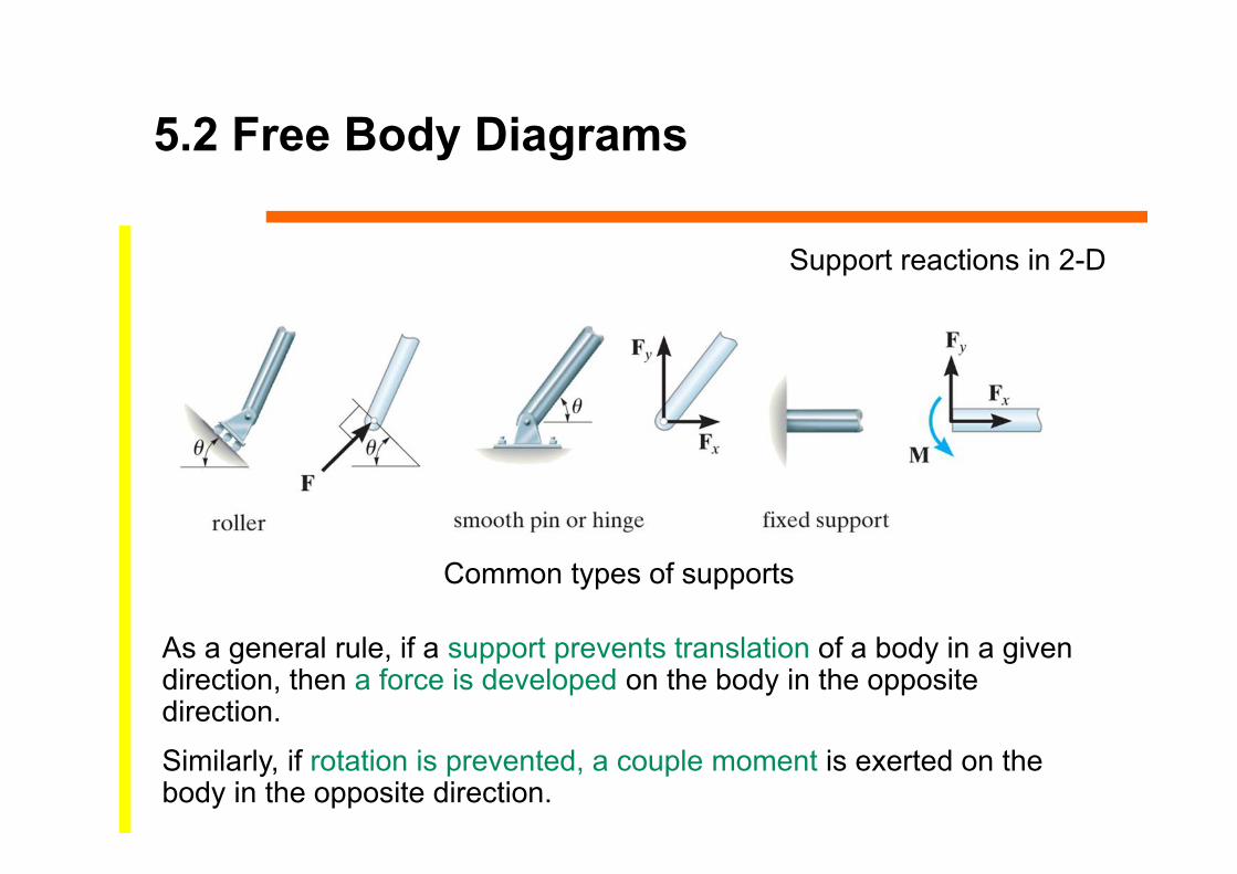
As a general rule, if a support prevents translation of a body in a given direction, then a force is developed on the body in the opposite direction.
Similarly, if rotation is prevented, a couple moment is exerted on the body in the opposite direction.
Common types of supports
Support reactions in 2-D

5.3 Equations of Equilibrium
• For equilibrium of a rigid body in 2D, ∑Fx = 0; ∑Fy = 0; ∑MO = 0
• ∑Fx and ∑Fy represent sums of x and y components of all the forces
• ∑MO represents the sum of the couple moments and moments of the force components

5.3 Equations of Equilibrium
Procedure for AnalysisFree-Body Diagram• Force or couple moment having an unknown
magnitude but known line of action can be assumed• Indicate the dimensions of the body necessary for
computing the moments of forces

5.3 Equations of Equilibrium
Procedure for AnalysisEquations of Equilibrium• Apply ∑MO = 0 about a point O • Unknowns moments of are zero about O and a direct
solution the third unknown can be obtained• Orient the x and y axes along the lines that will provide
the simplest resolution of the forces into their x and y components
• Negative result scalar is opposite to that was assumed on the FBD

Example
1. Put the x and y axes in the horizontal and vertical directions, respectively.
2. Determine if there are any two-force members.
3. Draw a complete FBD of the boom.
4. Apply the E-of-E to solve for the unknowns.
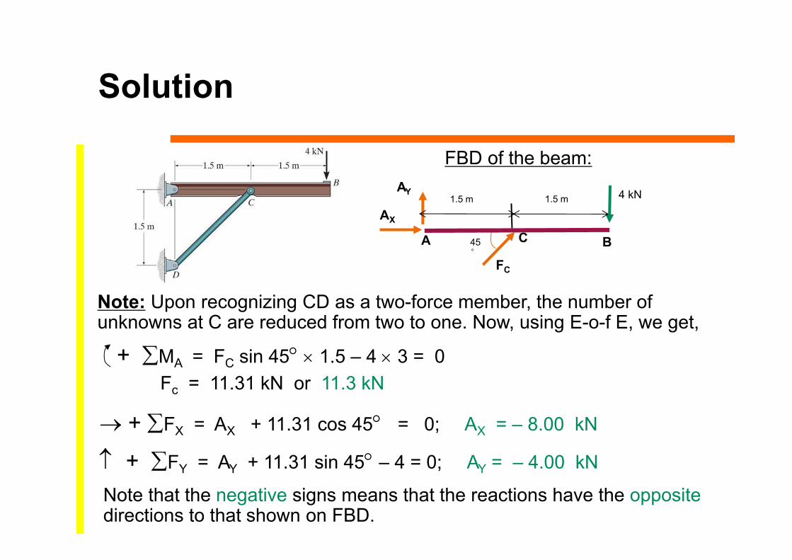
Given: The 4-kN load at B of the beam is supported by pins at A and C .
Find: The support reactions at A and C.
Plan:
Solution
Note: Upon recognizing CD as a two-force member, the number of unknowns at C are reduced from two to one. Now, using E-o-f E, we get,
+ FX = AX + 11.31 cos 45 = 0; AX = – 8.00 kN
+ FY = AY + 11.31 sin 45 – 4 = 0; AY = – 4.00 kN
+ MA = FC sin 45 1.5 – 4 3 = 0Fc = 11.31 kN or 11.3 kN
FBD of the beam:
AX
AY
A
1.5 m
C B
4 kN
FC
45°
1.5 m
Note that the negative signs means that the reactions have the oppositedirections to that shown on FBD.
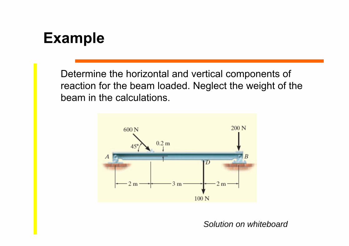
Example
Determine the horizontal and vertical components of reaction for the beam loaded. Neglect the weight of the beam in the calculations.
Solution on whiteboard