static and dynamic analysis of the old stone bridge in mostar
TRANSCRIPT

Građevinar 8/2012
655GRAĐEVINAR 64 (2012) 8, 655-665
UDK: 624.5.012.1:624.042/.046
Professional paperJure Radnić, Alen Harapin, Marija Smilović, Nikola Grgić, Mladen Glibić
Static and dynamic analysis of the old stone bridge in Mostar
The static and dynamic analysis results for the arch stone bridge in Mostar are presented. The analysis is based on the numerical model previously developed by the author for static and dynamic analysis of various types of masonry structures. Two bridge geometry models, with micro and macro modelling of masonry, are considered. The influence of vertical load, temperature change, and real earthquake action, is analyzed. The design deflections and crack zones in arch correspond well to the real life situation, which confirms reliability of the numerical model used. It is emphasized in the paper that the damage to the renovated stone arch should be remedied as soon as practicable.
Key words:old stone bridge in Mostar, renovation, damage, static and dynamic analysis, repair
Stručni radJure Radnić, Alen Harapin, Marija Smilović, Nikola Grgić, Mladen Glibić
Statička i dinamička analiza starog kamenog mosta u Mostaru
U radu su prikazani rezultati statičke i dinamičke analize lučnog kamenog mosta u Mostaru koristeći prethodno razvijeni numerički model autora za statičku i dinamičku analizu različitih tipova zidanih konstrukcija. Razmatrana su dva modela geometrije mosta, s mikro i makro modelom ziđa. Analiziran je utjecaj vertikalnih opterećenja, temperaturnih promjena i djelovanje realnog potresa. Proračunski progibi i zone pukotina u luku dobro se slažu sa stvarnim stanjem, što potvrđuje pouzdanost korištenog numeričkog modela. U radu se ukazuje na potrebu hitne sanacije oštećenja obnovljenog kamenog luka.
Ključne riječi:stari kameni most u Mostaru, obnova, oštećenja, statička i dinamička analiza, sanacija
FachberichtJure Radnić, Alen Harapin, Marija Smilović, Nikola Grgić, Mladen Glibić
Statische und dynamische Analyse der alten Steinbrücke in Mostar
In der Arbeit sind die Resultate der statischen und dynamischen Analyse der Bogensteinbrücke in Mostar dargestellt, wobei das vorher entwickelte numerische Modell des Autors für die statische und dynamische Analyse verschiedener Typen von Mauerkonstruktionen entwickelt wurde. Es wurden zwei Brückengeometrie - Modelle mit einem Mikro- und Makromodell des Mauerwerks in Erwägung gezogen. Ferner wurde der Einfluss von vertikalen Belastungen, Temperaturveränderungen und Wirkungen eines realen Erdbebens analysiert. Die berechneten Durchbiegungen und Risszonen in dem Bogen entsprechen sehr dem faktischen Zustand, womit die Verlässlichkeit des verwendeten numerischen Modells. In der Arbeit wird auf den Bedarf der dringenden Sanierung der Beschädigung des erneuerten Steinbogens hingewiesen.
Schlüsselwörter:Alte Steinbrücke in Mostar, Renovierung, Beschädigung, statische und dynamische Analyse, Sanierung
Static and dynamic analysis of the old stone bridge in Mostar
Primljen / Received: 19.1.2012.
Ispravljen / Corrected: 19.6.2012.
Prihvaćen / Accepted: 24.8.2012.
Dostupno online / Available online: 15.9.2012.
1 Prof.Jure Radnić, PhD. CE [email protected]
1 Prof. Alen Harapin, PhD. CE [email protected]
1 Marija Smilović, MEng. CE [email protected]
1 Nikola Grgić, MEng. CE [email protected]
2 Prof. Mladen Glibić, PhD. CE [email protected]
1 University of Split Faculty of Civil Engineering, Architecture and Geodesy2 University of Mostar Faculty of Civil Engineering
Authors:

Građevinar 8/2012
656 GRAĐEVINAR 64 (2012) 8, 655-665
Jure Radnić, Alen Harapin, Marija Smilović, Nikola Grgić, Mladen Glibić
1. Introduction
The old stone bridge over the restless and moody Neretva River was built in 1566 (Figure 1) by Hayruddin, an apprentice to the renowned Ottoman builder Kodža Mimar Sinan. It is considered to be one of the world’s most beautiful stone bridges. The bridge is inscribed on the UNESCO’s list of World Heritage Sites.
Figure 1. Old stone bridge in Mostar (before destruction)
The bridge is characterized by an extremely slender stone arch about 30 m in span, and 0.8 m in depth. The arch measures 3.95 m in width. It has 111 rows of stone blocks, each 0.4 m in width. Stone blocks forming the arch are linked together with metal cramps and dowels. Great skill of the bridge builders is manifested in many solutions applied on the bridge. The top point of the arch intrados is at 57.82 meters above sea level (asl), while the highest point of the walkway is at 60 m asl. An average level of streets leading to the bridge is at 55 m asl, and an average water level in the riverbed is at 42 m asl. The construction and exceptional beauty of this bridge have been depicted in many legends, stories and poems.The bridge superstructure was destroyed in 1993 during the recent war in Bosnia and Herzegovina. With the assistance of the European Union, the bridge and the surrounding structures were fully renovated and brought back to their original state in 2004. In November 2007, cracks were observed at several points along the stone arch of the bridge. The biggest measured crack width amounted to 8 mm. The cause of this cracking has not as yet been precisely determined. After bridge renovation, 6 earthquakes were registered in the period from 2006 to 2008 in the Mostar region. The magnitude of these earthquakes ranged from 2.6 to 4.5 on the Richter scale.Results obtained by static and dynamic analysis of the bridge are presented in the paper, based on the numerical model for nonlinear static and dynamic analysis of various types of masonry structures, as developed by the authors [1, 2]. The model enables simulation of the most significant nonlinear effects on the behaviour of masonry walls, concrete reinforcement, and soil (failure in compression, opening and closing of cracks in tension, tensile and shear stiffness of materials between cracks, shear failure, etc.), as well as simulation of changes in geometry
of the system. Two in-plane (2D) bridge-geometry models are considered. The influence of vertical load, temperature change, and real earthquake action, is analyzed.Results obtained during the analysis point to real stress situations in the structure, and to the bridge safety level, for the load values considered. In addition, probable causes of cracking in the stone arch of the bridge are also presented.
2. Some notes with regard to bridge renovation
The original bridge was renovated based on the photogrammetric survey made in 1982 [3]. The materials, solutions and construction procedures similar to those used during initial construction were applied, whenever possible, in the course of this renovation [4]. The cross section of the bridge is shown in Figure 2. The arch and outside longitudinal walls of the renovated bridge are made of the tenelija stone, i.e. of the same stone that was used during construction of the original bridge. In addition, the stone for the renovated bridge was extracted from the same quarry. The tenelija stone is characterized by very low strength, medium bulk density, extreme porosity, and great water absorption capability [5] (cf. Table 1). High water absorption causes significant reduction in strength if stone is wetted. On the other hand, this stone can easily be dressed, which is why it has been used quite often in construction. Upon extraction from the quarry, it can be cut with hand saw and dressed with usual tools. However, this stone gains in strength with the passing of time, and it should be stored in a protected place as long as possible prior to final placement. A harder type of limestone (crushed stone in mortar) is used for arch thickening at the spring, while the hardest sort of limestone is used for the pedestrian walkway on the bridge. Some data about the renovated bridge are given in Table 2 [4].
Figure 2. Cross section of the bridge
Bulk density 1977 kg/m3
Porosity 24,4 %Water absorption 9,47 %Saturation coefficient 0,67Dry compressive strength 32,9-45,0 MPaWet compressive strength 27,2-36,2 MPaFrost resistance not resistant
Table 1. Some data on the tenelija stone
Građevinar 8/2012
657GRAĐEVINAR 64 (2012) 8, 655-665
Static and dynamic analysis of the old stone bridge in Mostar
Table 2. Some data on the renovated bridge
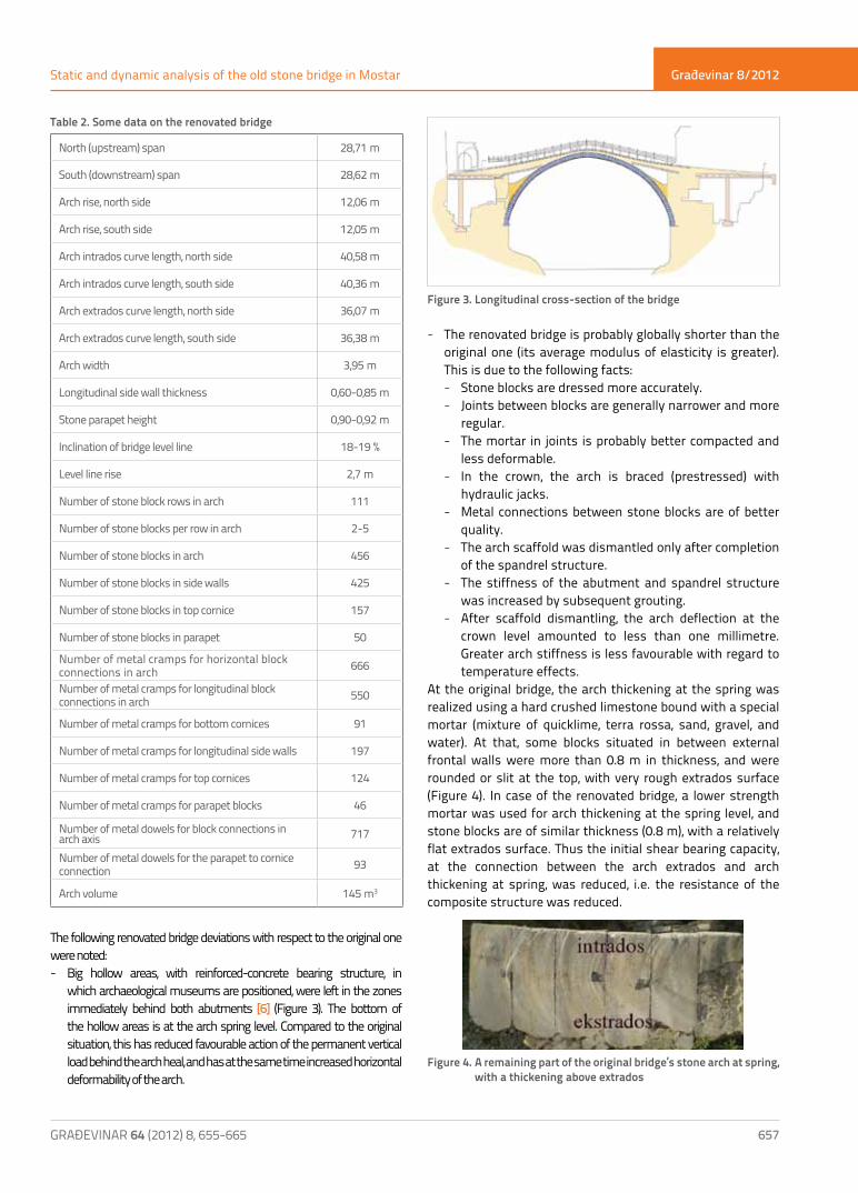
The following renovated bridge deviations with respect to the original one were noted: - Big hollow areas, with reinforced-concrete bearing structure, in
which archaeological museums are positioned, were left in the zones immediately behind both abutments [6] (Figure 3). The bottom of the hollow areas is at the arch spring level. Compared to the original situation, this has reduced favourable action of the permanent vertical load behind the arch heal, and has at the same time increased horizontal deformability of the arch.
Figure 3. Longitudinal cross-section of the bridge
- The renovated bridge is probably globally shorter than the original one (its average modulus of elasticity is greater). This is due to the following facts: - Stone blocks are dressed more accurately. - Joints between blocks are generally narrower and more
regular. - The mortar in joints is probably better compacted and
less deformable. - In the crown, the arch is braced (prestressed) with
hydraulic jacks. - Metal connections between stone blocks are of better
quality. - The arch scaffold was dismantled only after completion
of the spandrel structure. - The stiffness of the abutment and spandrel structure
was increased by subsequent grouting. - After scaffold dismantling, the arch deflection at the
crown level amounted to less than one millimetre. Greater arch stiffness is less favourable with regard to temperature effects.
At the original bridge, the arch thickening at the spring was realized using a hard crushed limestone bound with a special mortar (mixture of quicklime, terra rossa, sand, gravel, and water). At that, some blocks situated in between external frontal walls were more than 0.8 m in thickness, and were rounded or slit at the top, with very rough extrados surface (Figure 4). In case of the renovated bridge, a lower strength mortar was used for arch thickening at the spring level, and stone blocks are of similar thickness (0.8 m), with a relatively flat extrados surface. Thus the initial shear bearing capacity, at the connection between the arch extrados and arch thickening at spring, was reduced, i.e. the resistance of the composite structure was reduced.
Figure 4. A remaining part of the original bridge’s stone arch at spring, with a thickening above extrados
North (upstream) span 28,71 m
South (downstream) span 28,62 m
Arch rise, north side 12,06 m
Arch rise, south side 12,05 m
Arch intrados curve length, north side 40,58 m
Arch intrados curve length, south side 40,36 m
Arch extrados curve length, north side 36,07 m
Arch extrados curve length, south side 36,38 m
Arch width 3,95 m
Longitudinal side wall thickness 0,60-0,85 m
Stone parapet height 0,90-0,92 m
Inclination of bridge level line 18-19 %
Level line rise 2,7 m
Number of stone block rows in arch 111
Number of stone blocks per row in arch 2-5
Number of stone blocks in arch 456
Number of stone blocks in side walls 425
Number of stone blocks in top cornice 157
Number of stone blocks in parapet 50
Number of metal cramps for horizontal block connections in arch 666
Number of metal cramps for longitudinal block connections in arch 550
Number of metal cramps for bottom cornices 91
Number of metal cramps for longitudinal side walls 197
Number of metal cramps for top cornices 124
Number of metal cramps for parapet blocks 46
Number of metal dowels for block connections in arch axis 717
Number of metal dowels for the parapet to cornice connection 93
Arch volume 145 m3

Građevinar 8/2012
658 GRAĐEVINAR 64 (2012) 8, 655-665
Jure Radnić, Alen Harapin, Marija Smilović, Nikola Grgić, Mladen Glibić
- The arch geometry does not correspond to the geometry of the original bridge, but has imperfections (depression) at the south side, between the crown and side of arch toward the west [6] (real arch geometry before destruction). This is unfavourable from the aspect of stresses in arch.
- The construction of the initial bridge lasted nine years, while its renovation lasted less than two years. Consequently, the tenelija stone strength on the day the scaffold was dismantled from the renovated bridge was lower than the strength of stone in the original arch upon its completion.
3. Arch damage
The stone arch and some other parts of the original Old Bridge were repaired in 1963 [7]. It is now not known what kind of arch damage was repaired at that time. Photogrammetric survey of the original bridge, made in 1982 [3], and used as basis for bridge renovation, revealed cracks at the south face of the arch (Figure 5). After a detailed inspection of numerous remains of the original stone arch (Figure 6) was made in November 2011, many points of damage were noted at the intrados and face of the arch.
Figure 5. Cracks at the south face of the Old Bridge prior to collapse [3]
Stone edges between the arch face and arch intrados are cut at many places. At many parts of the arch face and intrados, detached stones are attached to the arch by metal anchors. Similarly, the strength of many stone blocks, whose cut or damaged parts were replaced by new smaller stone brocks, has been reduced. This repair work was locally done to very high quality standards, with joints hardly visible at the connection between the original stone block and new stone. However, in some instances, the repair work was conducted inadequately. Some areas at arch intrados and arch face were repaired by mortar and small-grained concrete. It can easily be seen that arch repairs were made in various periods of time. It is therefore clear that the original stone arch had accumulated, prior to bridge destruction, numerous instances of damage and repair during 427 years since its construction. Most points of damage and repair on arch faces are located next to intrados and, at intrados, next to arch faces.
Figure 6. Some points of damage and repair on remains of demolished bridge
The cracking was first noted on the renovated Old Bridge in 2007 [8]. The cracking registered at arch faces is shown in Figure 7. The greatest crack width amounted to 8 mm. In addition, a smaller number of cracks were registered at the arch intrados next to the left-side (east) bank of the river. Cracks revealed at the arch intrados in 2010 are shown in Figure 8 [9]. Besides cracks in stone blocks, the transverse horizontal detachment of blocks, perpendicular to the bridge plane, was also registered. It was noticed during bridge inspection conducted in November 2011 that crack zones previously registered on arch face [8] have extended along the length of the arch. The disposition of cracks is shown in Figure 9. The greatest crack width amounted to about 10 mm. Cracks were also registered at the arch intrados, as presented in paper [9], and as shown in Figure 8. No cracking or damage was registered at other parts of the superstructure.
Figure 7. Cracks at arch faces of the renovated bridge, registered in 2007 [8]
It can be seen that cracks at arch faces are almost parallel to the arch axis, and that they are close to the arch intrados. The cracking depth in the transverse direction of the arch is not known. It is assumed that cracks locally reach deep into the interior of external stone blocks, and that some have probably spread along the entire width of such blocks. It can also be noted that the cracking zone on the south face of the arch is greater than the one at the north face.

Građevinar 8/2012
659GRAĐEVINAR 64 (2012) 8, 655-665
Static and dynamic analysis of the old stone bridge in Mostar
Figure 8. Cracking at the intrados of the renovated arch, registered in 2010 [9]
The cracks at arch intrados are also oriented in the direction of the arch axis, and are disposed in several vertical planes along the bridge width. It can be seen that the greatest intrados damage is concentrated at the south face of the arch. Here also, it is not known what is the depth attained by the cracks. It is however assumed that they locally extend over the entire arch thickness.The above mentioned cracks in stone arch are due to the fact that tensile strengths (limit tensile deformations) of stone blocks in the direction perpendicular to the plane of these cracks have been exceeded. Tensile stresses (deformations) perpendicular to arch axis in two planes perpendicular to one another, i.e. these cracks, result from compressive stresses (deformations) in the direction of the arch axis.It is obvious that the renovated arch has suffered significant damage in just seven years after it has been rebuilt. The damage is probably greater than the one that had been suffered by the original stone arch seven years after its construction. This is evidently due to some inadequate solutions or actions during renovation of the bridge, which caused in such a short time serious damage to stone arch and the reduction of the initial mechanical resistance and safety of the renovated bridge. It is significant to note that the renovated and original arch have similar types of damage (cracking), with similar disposition at the faces and intrados of the arch.It is believed that the mentioned damage to the original arch and the renovated arch has dominantly been caused, in addition to
vertical loads, by temperature changes. The possibility that the extent of damage has been influenced by weak earthquakes that occurred after renovation has been ruled out, as additionally confirmed in the paper [8]. Small tensile strength of tenelija stone, out of which both the original arch and the renovated arch were built, is the main cause of cracking.
Figure 9. Cracks registered in 2011 at the faces of the renovated arch
Therefore, the cracking in both the original arch and the renovated arch was most probably caused the same load actions, probably of similar intensity. Greater damage to the renovated arch, when compared to the original one, is probably due to one or several of the following influences: - Increased stiffness of the stone arch – unfavourable
influence of temperature. - Increased horizontal deformability of the stone arch and
spandrel structure due to hollow areas realized behind of the arch spring.
- Reduced efficiency of connection between the arch spring and arch thickening above the extrados.
- Quality of new stone blocks is probably lower, when compared to original blocks (greater inhomogeneity of the structure and smaller tensile strength).
- Temperature conditions during arch closing at the crown were probably less favourable.
- Deviations in arch geometry.Numerical analyses of the bridge will be presented in the following section in order to prove position of registered cracks, and to identify possible causes of their occurrence.
4. Numerical analyses
The challenges of numerical modelling of structural behaviour lie inter alia in the need to describe as accurately as possible real geometry of structures and real behaviour of materials. Space (3D) models for determining geometry of structures are the most accurate, but are also the most demanding. For

Građevinar 8/2012
660 GRAĐEVINAR 64 (2012) 8, 655-665
Jure Radnić, Alen Harapin, Marija Smilović, Nikola Grgić, Mladen Glibić
them, appropriate numerical models of behaviour of materials are regularly less sophisticated and less reliable than those for models of simpler geometry (e.g. 2D or bar systems). If behaviour of structures can be described for relevant loads with sufficient precision using a simplified geometry model, which involves simpler and more transparent analysis, and especially if a reliable numerical model for behaviour of materials is used, then preference should be given to such models rather than to complex space models.For vertical static loads, temperature changes, and seismic accelerations in the plane of the bridge, the behaviour of the Old Bridge can reliably be described by an in-plane model of geometry (plane stress, with elements of appropriate width). A previously developed numerical model and the corresponding computer program for static and dynamic analysis of in-plane masonry structures [1, 2] is used in this analysis. The model will briefly be described in the section in which behaviour of masonry walls is modelled.An anisotropic model of behaviour, with different moduli of elasticity, shear moduli, strength values, and limit deformations in two directions perpendicular to one another, can be used for walls. The following is modelled: plasticisation and crushing of walls in compression, opening of cracks in walls in tension and their closing in compression, tensile and shear stiffness of cracked walls, and influence of shear on the failure of walls. Both the macromodel and micromodel of walls can be used.In the macromodel, the complex behaviour of walls (wall blocks connected with mortar or with other connecting substance) is described using replacement material with representative mechanical properties. In the micromodel, the simulation is possible at the level of joints (mortar) between wall elements, and also at the level of connection between mortar and wall element. Plate and bar contact elements can be used, with various connections between normal and shear stresses at the connection surface between different materials. The analysis with macromodel of walls is simpler, more transparent, and is less time consuming when compared to the wall micromodel analysis. The wall macromodel is especially suitable for large size real structures. The micromodel is appropriate for spatially simple structures only.
4.1 Numerical model NM1 for static load
In this model, the load bearing structure of the Old Bridge is represented solely by the stone arch, as it is the dominant structural element. This complies with the assumption, believed to be close to reality, that in case of this bridge the contribution of the spandrel structure to the arch, in the sense of taking on some of the load, is low for many reference load values. In fact, it is considered that here the stiffness and bearing capacity of the stone arch exceed by many times the stiffness and bearing capacity of the spandrel structure.The stone arch has considerable curvature, with radial arrangement of regular dressed stone blocks, additionally stiffened with metal
cramps and dowels. Joints between the stone blocks are thin, of good quality, dominantly in compression, and are slightly compressible. This is why the arch is characterized by a very low deformability in vertical plane.External longitudinal spandrel walls are formed of stone blocks laid in horizontal layers. While the arch withstands the compressive load, the spandrel structure dominantly responds to bending load. The efficiency of the composite system formed of the arch and spandrel structure is dominantly influenced by the efficiency of transfer of shear stresses in horizontal joints of spandrel walls, and especially at the contact of the arch extrados with the arch thickening at arch spring, and with longitudinal walls. As in these joints the shear bearing capacity is relatively low, and as spandrel walls can not transfer compressive stress to the top third of their height at the connection with the abutment [4], the load bearing capacity of the spandrel structure can be considered practically negligible with regard to vertical load and temperature action. At that, it should once again be noted that the renovated bridge, when compared to the original one, probably has a lower limit bearing capacity of the spandrel structure because of the more flexible shear connection between the stone arch and its thickening at arch spring, and because of the hollow zone situated in abutment, immediately after the arch spring.The arch discretisation by finite elements is shown in Figure 10. The deformed arch geometry, as selected during bridge renovation [3], with the wall micromodel [1, 2], was adopted. In this geometry model, each stone block along the arch axis is modelled by finite elements of equal width. Along the arch height, each stone block was modelled with four finite elements. The mortar between the stone blocks was simulated by contact elements 6 mm in thickness, corresponding to the width of joints. The connection of stone blocks along the arch extrados was simulated with metal cramps (tension bar elements), while the link between stone blocks in the arch axis was simulated with metal dowels (shear bar elements). Appropriate boundary conditions were applied at the connection between the arch and massive abutments
Figure 10. Bridge structure geometry model NM1
A special attention was paid to the definition of appropriate mechanical parameters of stone blocks, mortar (mortar to stone connection), and metal connections between stone blocks, based on literature information [4, 6]. Basic parameters

Građevinar 8/2012
661GRAĐEVINAR 64 (2012) 8, 655-665
Static and dynamic analysis of the old stone bridge in Mostar
for materials, as adopted in the analysis, are shown in Table 3. The arch was approximated by in-plane stress, with elements each 3.95 m in thickness. It was analyzed for vertical loads and temperature action.
Tablica 3. Basic parameters for materials adopted in the NM1 model
4.1.1. Analysis results for vertical load only
Some analysis results for vertical load only (self-weight of the arch, spandrel structure weight, and pedestrian load) are presented in Figure 11. The pedestrian load of 5 kN/m2 was assumed along the entire walking surface of the bridge. It amounts to as little as 7 percent of the total permanent load.The design deflection of arch in the crown amounts to 0.94 mm, which almost corresponds to the displacement of 0.9
mm as measured after the scaffold was released (south side) [10]. In the direction of axis, the arch dominantly assumes compressive load and this along the entire thickness. The biggest main compressive stress in the arch amounts to -1.86 MPa. Tensile stresses in stone blocks do not exceed the tensile strength of the stone, i.e. there are no cracks in stone blocks.
4.1.2. Analysis results for simultaneous action of vertical load and temperature changes
The stress in arch due to temperature changes was activated after the final arch closing at the crown level (21 August 2003). In fact the arch was closed in crown in the summer period, at the ambient temperature of about 25 °C. Annual temperature variations in the town of Mostar are quite big, and mostly range from -5 °C to 50 °C [8]. Different annual and diurnal temperature variations are also possible along the arch length and thickness. For simplicity of analysis, we assumed that the temperature is constant along the arch length, and variable along the arch thickness. Some temperature changes, believed to be possible and ranking among the most unfavourable ones, are presented in Figure 12. Relevant temperature variations are those that cause pressure next to the arch intrados, as compared to the pressure situation at the arch closing time. The temperature coefficient of αTb= 6,5 x10⁻⁶ was assumed for stone blocks, and this coefficient in joints was assumed to be αTm=6,0 x10⁻⁶. Some results obtained for simultaneous action of vertical load and temperature changes according to Figure 12a are shown in Figure 13. The highest main compressive stress in stone blocks amounts to -3.48 MPa. The design position of cracks in stone blocks at the arch face is shown in Figure 14, which corresponds well to the actual present time cracks shown in Figure 9.Design cracks in vertical plane of the arch along the intrados (overstepping of limit tensile deformation of stone perpendicular to the arch) were also obtained. This is consistent with the actual situation according to Figure 8.It should be noted that analysis results depend on various stone and mortar parameters, and especially on the tensile strength, elastic modulus, Poisson ratio, and temperature coefficient. Numerous analyses were made by varying these parameters. Due to limited space, not all of these results can be presented in the paper. The following conclusions can be made after analysis of influence exerted by the above mentioned parameters for materials:
Material Usvojeni parametri
Tenelija stone
elastic modulusPoisson ratio shear moduluscompressive strengthtensile strengthlimit compressive strainlimit tensile strain
Eb= 2,3x10⁴ MPaνb= 0,3Gb= 8,84x10³ MPafcb= 35 MPaftb=3 MPaεbu= –0,0035εtu= 0,001
Mortar
elastic modulusPoisson ratio shear moduluscompressive strengthtensile strengthlimit compressive strain
Em= 3x10³ MPaνm= 0,20Gm= 1,34x10³ MPafcm= 8 MPaftm= 0,4 MPaεmu= –0,0035
Cramps and
dowels
elastic modulustensile strengthlimit tensile strain
Es= 2x10⁵ MPafst= 100 MPaεsu= 0,01
Figure 11. Some numerical results for vertical load only (permanent load and pedestrians) – NM1 model Figure 12. Some temperature changes along the arch thickness

Građevinar 8/2012
662 GRAĐEVINAR 64 (2012) 8, 655-665
Jure Radnić, Alen Harapin, Marija Smilović, Nikola Grgić, Mladen Glibić
- Lower tensile strength of stone results in a wider stone cracking zone.
- Higher elastic modulus, and higher temperature coefficient of stone, result in unfavourable temperature effects.
- Higher Poisson ratio of stone results in greater deformations and greater tensile stress in stone block perpendicular to the arch axis..
Model Some results for simultaneous action of vertical load and temperature changes according to Figure 12c are presented in Figure 14. It can be seen that, for this possible load, the crack zones extend along the entire length of the arch next to the intrados, which unfortunately can happen at some future time on the real arch. Compressive stress values in stone arches attain – 3.79 MPa.
4.2. Numerical model NM2 for static and dynamic load
This in-plane model of bridge structure geometry includes the arch, spandrel structure, and abutments, with elements of appropriate width and with appropriate properties of materials used in individual parts of the bridge. In the wall macromodel adopted in the analysis [1, 2], the complex behaviour of mortar-bound stone blocks was simulated using a representative model of materials with equivalent properties. The influence of cramps along the extrados was
Figure 14.. Some results for vertical load and temperature changes according to Figure 12c – NM1 Model
Figure 13. Some results for vertical load and temperature changes according to Figure 12a – NM1
Table 4. Basic parameters for materials adopted for the NM2 model
Element Usvojeni parametri materijala
Stone arch
elastic modulusPoisson ratio shear moduluscompressive strengthtensile strengthlimit compressive strainlimit tensile strain
Eb= 2,3x10⁴ MPa νb= 0,3Gb= 8,84x10³ MPafcb= 35 MPaftb=3 MPaεbu= –0,0035εtu= 0,001
Abutment
elastic modulusPoisson ratio shear moduluscompressive strengthtensile strengthlimit compressive strain
Ea= 3x10³ MPaνa= 0,2Ga= 1,34x10³ MPafca= 10 MPafta= 0,4 MPaεau= –0,0035
Spandrel structure
elastic modulusPoisson ratioshear moduluscompressive strengthtensile strengthlimit compressive strain
Es= 3x10³ MPaνs= 0,2Gs= 1,34x10³ MPafcs= 10 MPafts= 0,4 MPaεsu= –0,0035
Metal cramps
elastic modulustensile strengthlimit tensile strain
Es= 2x10⁵ MPafst= 100 MPaεsu= 0,01
included in the arch model. Basic parameters for materials, adopted for this model, are presented in Table 4.
Građevinar 8/2012
663GRAĐEVINAR 64 (2012) 8, 655-665
Static and dynamic analysis of the old stone bridge in Mostar
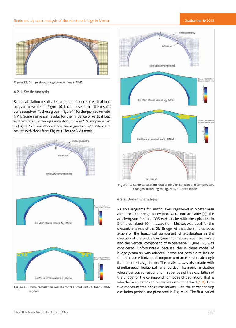
Figure 15. Bridge structure geometry model NM2
4.2.1. Static analysis
Some calculation results defining the influence of vertical load only are presented in Figure 16. It can be seen that the results correspond well To those given in figure 11 for the geometry model NM1. Some numerical results for the influence of vertical load and temperature changes according to figure 12a are presented in Figure 17. Here also we can see a good correspondence of results with those from Figure 13 for the NM1 model.
4.2.2. Dynamic analysis
As accelerograms for earthquakes registered in Mostar area after the Old Bridge renovation were not available [8], the accelerogram for the 1996 earthquake with the epicentre in Ston area, about 60 km away from Mostar, was used for the dynamic analysis of the Old Bridge. At that, the simultaneous action of the horizontal component of acceleration in the direction of the bridge axis (maximum acceleration 5.6 m/s2), and the vertical component of acceleration (Figure 17), was considered. Unfortunately, because the in-plane model of bridge geometry was adopted, it was not possible to include the transverse horizontal component of acceleration, although its influence is significant. The analysis was also made with simultaneous horizontal and vertical harmonic excitation whose periods correspond to first periods of free oscillation of the bridge for the corresponding modes of oscillation. That is why the task relating to properties was first solved [1, 2]. First two modes of free bridge oscillations, with the corresponding oscillation periods, are presented in Figure 19. The first period
Figure 16. Some calculation results for the total vertical load - NM2 model)
Figure 17. Some calculation results for vertical load and temperature changes according to Figure 12a – NM2 model

Građevinar 8/2012
664 GRAĐEVINAR 64 (2012) 8, 655-665
Jure Radnić, Alen Harapin, Marija Smilović, Nikola Grgić, Mladen Glibić
of free oscillations of the bridge amounts to 11.58 s, while the second one amounts to 13.84 s. This corresponds well to the corresponding values obtained by measurement [11] (T1=11,43 s, T2=13,96 s) . Only some calculation results are presented.
Figure 19. First two modes of free oscillation of the bridge
The arch displacement in crown for the Ston earthquake according to Figure 18 is presented in Figure 20. At that the following cases were analyzed: (i) only permanent load and earthquake and (ii) permanent load, temperature changes according to Figure 12a, and earthquake. In both cases, a sudden increase in displacement and crushing of materials, i.e. the divergence of numerical procedure or structural failure, occurs near the end of the earthquake action.
Figure 18. Accelerogram of the 1996 Ston
Figure 20. Arch displacement in crown for the Ston earthquake according to Figure 18
Figure 21. Displacement in arch crown for the scaled Ston earthquake (greatest horizontal acceleration: 0.3g)
Figure 22. Stress in stone block at arch spring next to intrados for the scaled Ston earthquake (greatest horizontal acceleration 0.3g)

Građevinar 8/2012
665GRAĐEVINAR 64 (2012) 8, 655-665
Static and dynamic analysis of the old stone bridge in Mostar
Some calculation results for the scaled Ston earthquake, with the biggest horizontal acceleration of 0.3g, are presented in Figures 21-23. Despite severe damage (cracking), the bridge structure "survived" in the following cases of load: (i) permanent load and earthquake, and (ii) permanent load, temperature changes according to figure 12a, and earthquake.
5. Conclusion
Calculated deflections and crack zones in the stone arch correspond well to the real situation. This confirms that the numerical bridge simulation models used in the analysis are reliable. Over more than four hundred years from its construction to demolition, the original bridge has accumulated much damage and its arch had been repaired, with greater or smaller success, in many instances. After renovation, the arch of the Old Bridge has suffered considerable damage in the period of no more than seven years. Positions of cracks and damage in the stone arch of the renovated bridge are very similar to those in the original bridge. In addition to vertical load, it is believed that temperature influences are the main cause of cracking both in the original and the renovated arch. The cracking in arch is due to overstepping of the tensile strength limit (limit tensile deformation) of stone in the
directions perpendicular to longitudinal compressive stresses (deformations) in the arch. Tensile stresses (deformations) perpendicular to the arch axis cause compressive stresses (deformations) in the direction of the arch axis. The main cause of damage in both the original and the renovated stone arch is an inadequate quality of tenelija stone with which the arch was built and, more particularly, a small tensile strength of this stone. Great damage to the renovated arch over a short period of time is probably due to deviations from some solutions that had been used for the original bridge.In the renovated bridge, great hollow zones were realized immediately after the arch spring at abutments, which is unfavourable for the arch (higher longitudinal horizontal displacements) and for the abutment. The shear connection between the stone arch and its thickening at the spring level is more flexible in case of the renovated bridge, i.e. the stiffness of the arch-spandrel structure composite system is lower. As the strength of the tenelija stone increases considerably over time, and taking into account the fact that the original bridge was built in seven years, while the renovated one in les than two years, it is obvious that the strength of the renovated arch was lower upon the removal of scaffold from the arch, when compared to the situation with the original bridge. It is quite possible that a better quality stone had been used for the original bridge. The superstructure of the renovated bridge is probably stiffer, which is unfavourable with regard to temperature effects. The renovated arch geometry, with an intentionally realized imperfection with respect to the original bridge, is less favourable for stresses in the arch. The deflection of the original bridge has until now been attributed to the yielding of scaffold during construction. It is however possible that this deflection is the result of the long term continuous displacement in the softened arch zone (tenelija stone creep rate is probably high), as the real and calculated arch displacements are the greatest in this zone.The extent of ach damage at the renovated bridge is such that its original mechanical resistance and safety have been reduced. It is probable that the situation will continue to deteriorate over time. Already at this time, there is a real danger that the pieces of damaged stone blocks might fall out. The repair of arch damage is urgently needed, which should include preparation of the study that is to propose appropriate solutions for the avoidance or reduction of further arch damage, and define the need for its durable successive repairs, in the ways similar to the original arch.
Figure 23. Stress in metal cramp in arch crown for the scaled Ston earthquake (greatest horizontal acceleration 0.3g)
REFERENCES[1] Radnić, J. Matešan, D., Harapin, A., Trogrlić, B., Smilović, M.,
Grgić, N., Baloević, G.: "Numerički model za analizu zidanih konstrukcija”, Građevinar, 63, p.p. 529-546, 2011.
[2] Radnić, J., Matešan, D., Harapin, A., Smilović, M., Grgić, N.: "Numerical Model for Static and Dynamic Analsis of Masonry Structure", 5nd International Conference on Advanced Computational Engineering and Experimenting, Abstract book ACE-X 2011, Algarve, 2011.

Građevinar 8/2012
GRAĐEVINAR 64 (2012) 8, 1-10666
Jure Radnić, Alen Harapin, Marija Smilović, Nikola Grgić, Mladen Glibić
[3] Geodetski fakultet Sveučilišta u Zagrebu: "Fotogrametrijska snimka Starog mosta u Mostaru", Zagreb, 1982.
[4] Gotovac, B.: "Ponovna izgradnja Starog mosta", Ceste i mostovi, Vol. 50, No 7-9, p.p. 23- 33, 2004.
[5] Šaravanja, K., Čolak, I.: "Kamen za obnovu Starog mosta u Mostaru", Prvi sabor hrvatskih mostograditelja, Brijuni, VI, 2005.
[6] General Engeneering: "Dijelovi glavnog projekta ponovne izgradnje Starog mosta", Firenca, 2002.
[7] CONEX and YERALTI ARAMACILIK: "Reconstruction of the Olde Bridge in Mostar", SM 001-IMR-01, 2000.
[8] Glibić, M.: "A possible reasons of cracks on the arch of the Old Bridge", International Scientific Symposium, Mostar, 2008.
[9] IGA plan d.o.o.: Izvještaj sa trodimenzionalnog 3D snimanja Starog mosta u Mostaru, Mostar, 2010.
[10] PROTON d.o.o.: "Geodetic recording of cracks on the Old Bridge", Mostar, 2008.
[11] Krstevska, L., Kustura, M., Tashkov, Lj.: "Experimental dynamic testing of the Old Bridge in Mostar", International Scientific Symposium, Mostar, 2008.